Article

Transient Vortex Dynamics in Tip Clearance Flow of a Novel Dishwasher Pump

1
School of Mechanical Engineering, Changzhou Institute of Technology, Changzhou 213032, China
2
National Research Center of Pumps, Jiangsu University, Zhenjiang 212013, China
3
Machinery Technology Development Co., Ltd., Beijing 100080, China
*
Author to whom correspondence should be addressed.
Machines 2025, 13(8), 681; https://doi.org/10.3390/machines13080681
Submission received: 2 July 2025 / Revised: 28 July 2025 / Accepted: 1 August 2025 / Published: 2 August 2025

Abstract

Blade tip leakage vortex (TLV) is a critical phenomenon in hydraulic machinery, which can significantly affect the internal flow characteristics and deteriorate the hydraulic performance. In this paper, the blade tip leakage flow and TLV characteristics in a novel dishwasher pump were investigated. The correlation between the vorticity distribution in various directions and the leakage vortices was established within a rotating coordinate system. The results show that the TLV in a composite impeller can be categorized into initial and secondary leakage vortices. The initial leakage vortex originates from the evolution of two corner vortices that initially form at different locations within the blade tip clearance. This vortex induces pressure fluctuations at the impeller inlet; its shedding is identified as the primary contributor to localized energy loss within the flow passage. These findings provide insights into TLVs in complex pump geometries and provide solutions for future pump optimization strategies.

1. Introduction

A novel dishwasher pump features direct contact with the clean dishes without a pipeline in the water tank. As shown in Figure 1, the impeller adopts a special composite structure without distinct front and rear cover plates. The outlet consists of multiple nozzles positioned at different locations and orientations along the volute. The complex impeller is composed of axial flow cascades at the bottom and centrifugal blades at the top. However, tip leakage flows arising from the clearances between the composite impeller, guide ring, and rotating double-tongue volute can interfere with and block flow channels by the resultant tip leakage vortices (TLVs). This phenomenon poses critical hydraulic design challenges, including significant energy losses and reduced efficiency.
In recent years, research studies have been conducted on the internal flow mechanisms, dynamic and static interference mechanisms, and pressure pulsation characteristics in novel dishwasher pumps. Zhu et al. [1,2] conducted a study on the unsteady pressure pulsations in a novel dishwasher pump. The findings reveal distinct flow mechanisms between single-tongue and double-tongue volutes, as well as among volutes themselves, under both static and rotational conditions. Li et al. [3] optimized the composite impeller using an orthogonal experimental approach, with a particular emphasis on the curvature profile of the axial flow cascade as a crucial optimization parameter. Ning et al. [4] performed unsteady numerical simulations of novel dishwasher pumps operating at various volute speeds. The findings revealed that the rotational speed of the double-tongue volute had minimal impact on pump performance but primarily influenced the flow field in the transition zone between the impeller and the volute.
In turbomachines, a tip clearance exists between the impeller and the end wall, which causes the tip leakage flow [5,6]. Tip clearance is essential to avoid friction between the rotating and stationary parts; however, the resulting tip leakage flow through the clearance inevitably causes energy losses and reduced efficiency [7]. Since the 1950s, tip leakage flow has been a subject of significant interest and extensively studied in experiments and numerical simulations [8,9,10,11]. For instance, Tang et al. [12] identified four distinct vortex structures induced by blade tip leakage flow in micro centrifugal pumps: backflow vortex, passage vortex, primary tip leakage vortex (PTLV), and separation tip leakage vortex (STLV). The PTLV originates at the blade’s leading edge and propagates downstream, gradually separating into the STLV under the influence of secondary flow. Notably, the passage vortex exhibits the most significant impact on intra-passage pressure pulsation characteristics. Guo et al. [13] numerically demonstrated that reducing the inner tip clearance radius in high-speed centrifugal pumps with inducers enhances hydraulic performance; however, it concomitantly amplifies pressure pulsation amplitudes. Furthermore, tip clearance leakage jets generate low-pressure vortex zones at the inducer inlet. Zhang et al. [14] compared the efficacy of Q-criterion and Liutex vortex identification methods in resolving impeller–tip clearance vortex interactions. Li et al. [15] quantified tip clearance effects on axial flow pump performance and localized high-energy dissipation regions. Qian et al. [16] revealed flow-rate-dependent vortex dynamics: high-flow conditions promote tip leakage vortex formation at the impeller outlet, whereas low-flow conditions induce leading-edge backflow vortices. Additionally, the interface between mainstream flow and tip leakage vortices migrates upstream with decreasing flow rate. Kan et al. [17] established that the tip leakage vortex morphology in axial-flow pump–turbines is governed by impeller inlet flow angle, with associated hydraulic losses primarily attributed to turbulent dissipation. Under high-flow conditions, wall dissipation sharply increases due to leakage vortices. Rafiee et al. [18] examined the influences of relative tip clearance on the efficiency and loss mechanisms in a radial outflow turbine; the results indicate that as the relative tip clearance increases, the turbine efficiency and power output stabilize at a certain level.
To sum up, the interaction between the tip leakage flow and the mainstream results in the formation of TLVs, which induce flow separation, disrupt the flow field structure, and lead to energy loss in the pump, subsequently degrading its performance [19,20,21]. It is well established that TLV and its induced cavitation can threaten the stable operation of an axial flow pump due to its detrimental effects [22]. Although extensive research has addressed tip leakage vortices (TLVs) in axial flow pumps, the compound-stage impeller in novel dishwasher pumps exhibits substantially distinct hydrodynamic characteristics compared to conventional designs, demanding further investigation. Key factors governing TLV structural variations require systematic elucidation, and the underlying flow mechanisms remain insufficiently explored. This study aims to delineate internal flow patterns and decipher TLV formation mechanisms with their concomitant effects in the axial domain of a novel dishwasher pump. Specifically, the objectives are to (1) study the generation and evolution mechanism of leakage vortex structure, (2) study the correlation characteristics between vortex structure and pressure fluctuations in the flow channel, and (3) reveal the energy loss characteristics caused by tip clearance flow. The paper is structured as follows: Section 2 presents the computational fluid dynamics (CFD) methodology and validation approach. Section 3 validates the numerical model against experimental pump characteristics. Section 4 quantifies TLV impacts and associated energy loss pathways. Finally, Section 5 synthesizes key findings and provides design implications.

2. Numerical Model and Simulation Setup

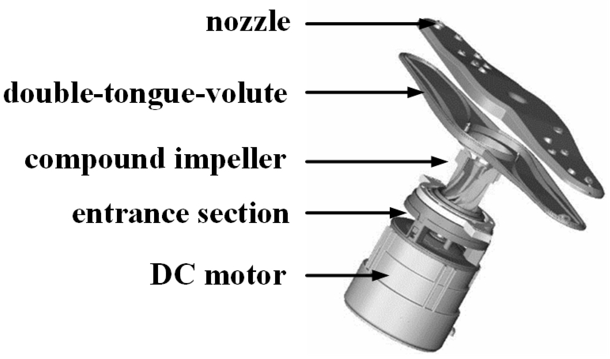
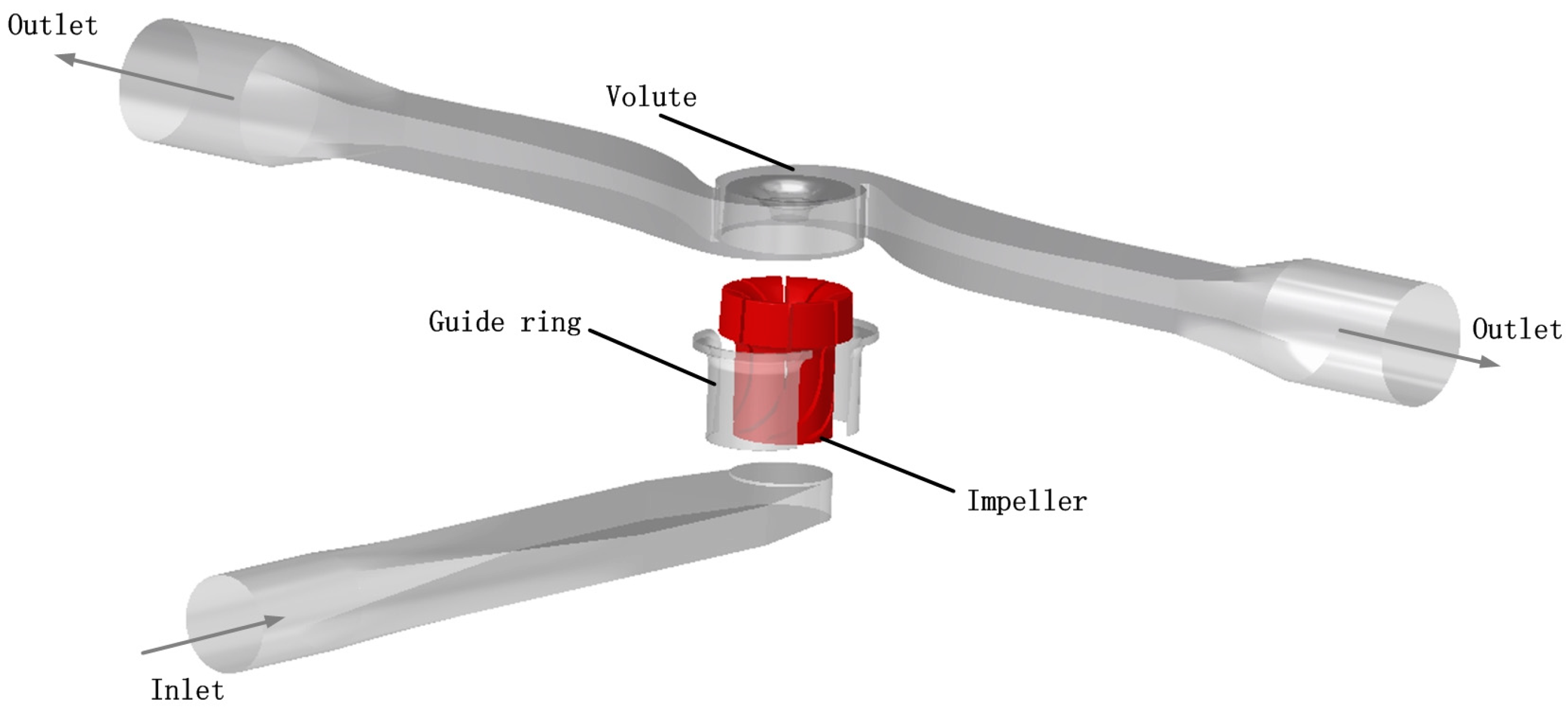
2.1. Computational Domain

To mitigate measurement uncertainties arising from the absence of pipeline connections and volute passive rotation, simplified inlet and outlet piping systems were implemented for performance quantification. Figure 2 illustrates the physical model configuration, comprising a suction pipe with circular cross-section (diameter Din = 32 mm), an 8-blade impeller, and a double-volute casing with bifurcated discharge channels. An inlet guide ring (clearance = 0.5 mm) facilitates the hydraulic transition between the suction pipe and volute domain. Critically, to counteract nozzle reaction forces during measurement, dual symmetrical outlet pipes (Dout = 40 mm) replace the conventional volute nozzle, with their centerlines intersecting the impeller rotational axis. The outlet cross-sectional area was calibrated against equivalent nozzle dimensions. Both inlet and outlet pipes incorporate extended straight sections to ensure fully developed flow and precise pressure tap placement. Table 1 summarizes key design parameters of the novel dishwasher pump system.

2.2. Governing Equations

The Navier–Stokes (N-S) equations govern the turbulent motion of incompressible fluids, solvable under prescribed initial and boundary conditions. The governing system comprises the continuity equation and momentum conservation equations [23]:
ρ t + ( ρ u j ) x j = 0
( ρ u i ) t + ( ρ u i u j ) x j = p x i + x j ( μ u i t ρ u i u j ¯ ) + S M
where ui and uj represent the fluid velocity components in the i and j directions, t represents time, p represents pressure, ρ represents fluid density, and μ represents dynamic viscosity. SM is the generalized source term of the momentum conservation equation.
Resolving turbulent flows directly via the Navier–Stokes equations remains computationally prohibitive due to the coexistence of vortices that span multiple length and time scales. Consequently, the Reynolds-averaged Navier–Stokes (RANS) equations are employed, which decompose flow variables into ensemble-averaged and fluctuating components through Reynolds decomposition. The standard k-ε turbulence model, a two-equation closure scheme, solves transport equations for turbulent kinetic energy (k) and dissipation rate (ε).

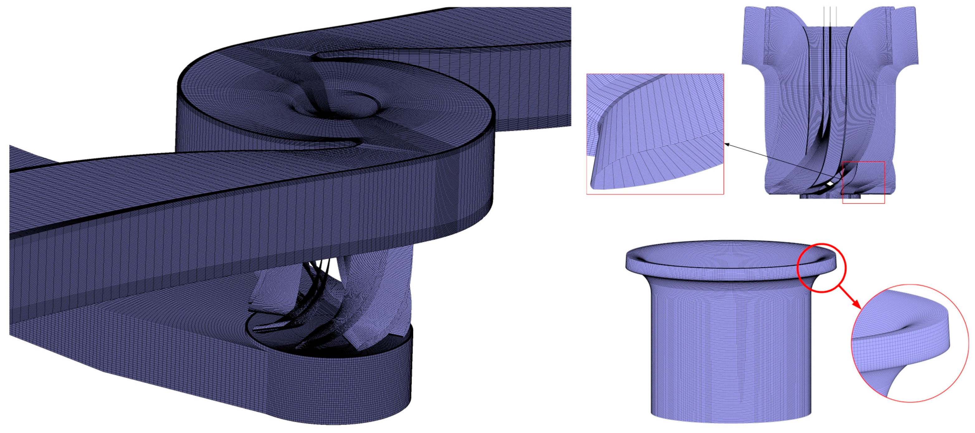
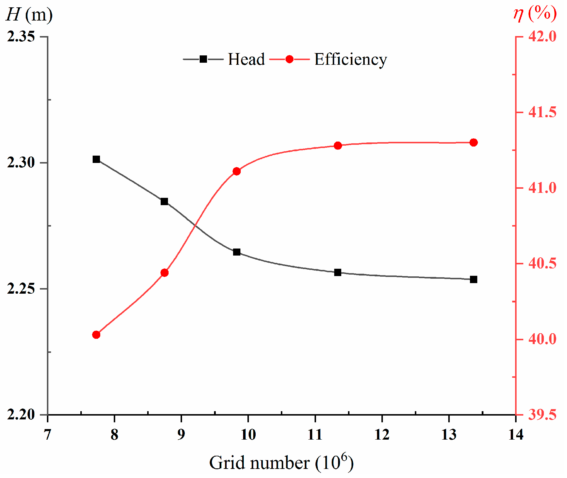
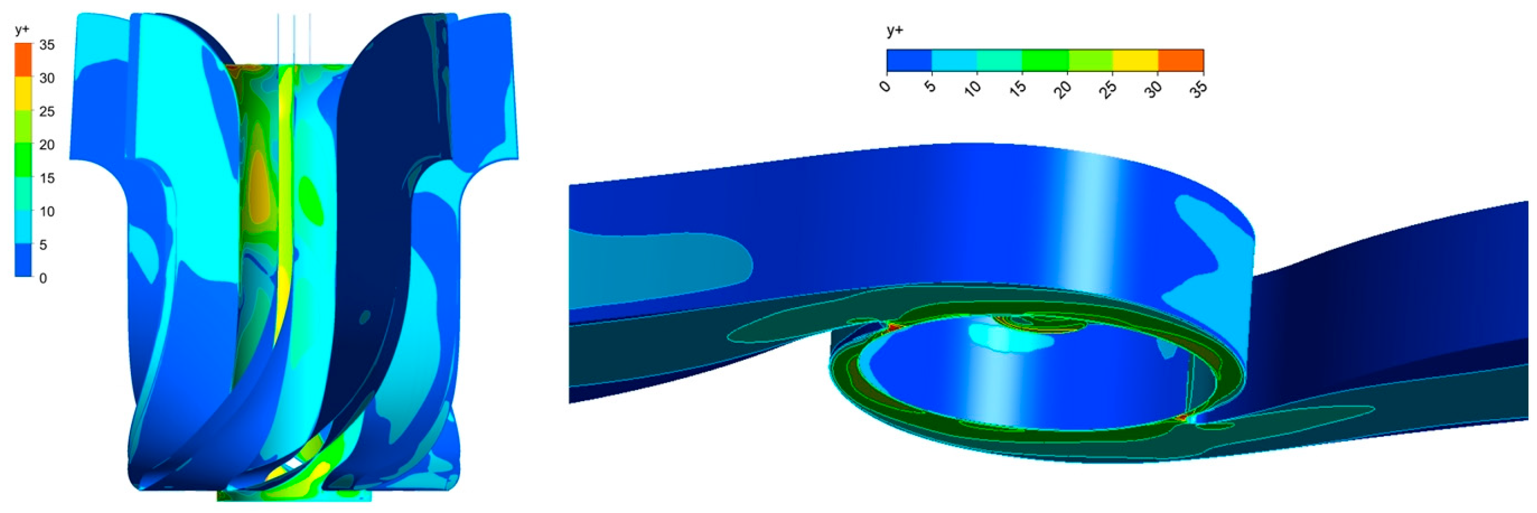
2.3. Mesh Generation

The computational domain was discretized using structured hexahedral meshes generated in ICEM CFD. For the impeller domain, a hybrid J-grid/O-grid topology was implemented to conform to the blade geometry. Leveraging rotational periodicity, a single-blade passage mesh was circumferentially duplicated to construct the full impeller, with near-wall refinement. Given the 0.5 mm tip clearance, localized mesh refinement was applied within this critical region, as illustrated in Figure 3.
In numerical simulations, grid density is an important factor affecting the accuracy of computational results. To assess the impact of grid density on simulation results, five different grid schemes with different grid numbers N1 through N5 were set up for simulation, with each grid number increasing by one. The grid number of N1 to N5 are shown in Table 2. Pump head and efficiency are selected as the two performance parameters for grid error analysis. The grid independence verification is shown in Figure 4. The variations in head and efficiency decrease with the increase in grid number (mesh becomes finer). Taking the N5 scheme as a reference, the relative error between scheme N4 and scheme N5 is less than 0.3%. Therefore, based on the grid independence criteria, both N4 and N5 grid schemes meet the simulation requirements. Considering the trade-off between computational cost and accuracy, a grid scheme N4 with 11.34 million units is adopted.

2.4. Numerical Settings and Boundary Conditions

Numerical simulations were performed using ANSYS Fluent 19.0. The numerical simulation parameters are shown in Table 3. The standard k-ε turbulence model with default constants was implemented. All solid walls employed no-slip boundary conditions with scalable wall functions. Transient simulations were initialized from converged steady-state solutions, with time-averaged flow fields extracted for analysis. The pressure-based coupled solver utilized second-order spatial discretization, with convergence criteria set at 10−4 for continuity/momentum equations and 10−3 for turbulence equations. Mass-flow inlet and pressure-outlet conditions were imposed at respective boundaries.
Transient simulations employed the SIMPLEC algorithm for pressure–velocity coupling. Convection terms in the momentum, turbulent kinetic energy (k), and dissipation rate (ε) equations were discretized using a second-order upwind scheme. The transient formulation adopted a second-order implicit temporal discretization. Three rotor–stator interfaces connected the four fluid domains via a transient rotor–stator model. Unsteady Reynolds-averaged Navier–Stokes (URANS) equations were solved with boundary conditions consistent with steady-state simulations. The time step Δt = 2.22 × 10⁻⁴ s (equivalent to 1/90th of the impeller rotation period T) was determined through rigorous time-step independence verification.
The y+ criteria of the simulation were considered to assess the mesh quality. The maximum y+ value was below 35, as shown in Figure 5.

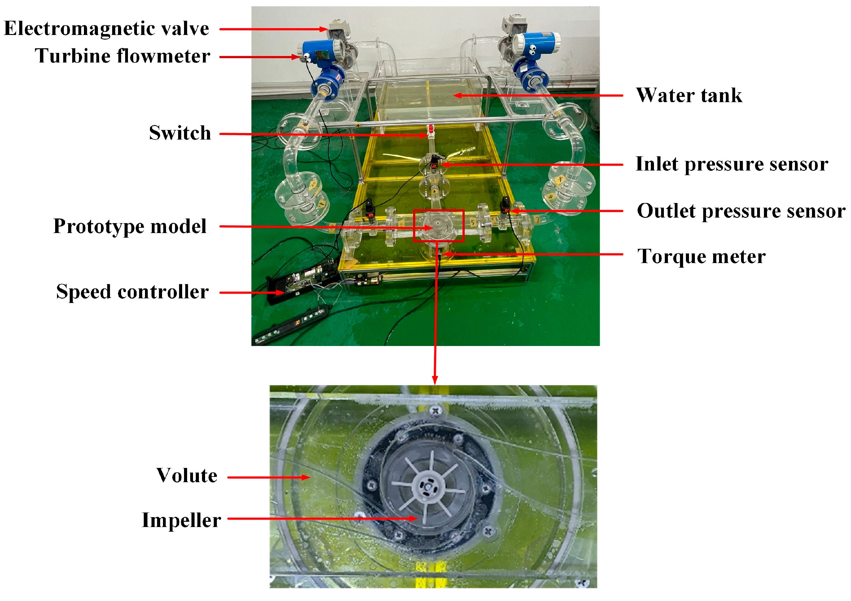
3. Experimental Characterization of Pump Performance

Figure 6 illustrates the performance test rig for the novel dishwasher pump. The hydraulic circuit comprises polymethyl methacrylate (PMMA) components, including the water tank, inlet/outlet pipelines, and volute casing. The impeller was fabricated via stereolithography, with special consideration for structural integrity given its thin-walled geometry (blade thickness = 1.5 mm). During testing, the inlet valve maintained full-open status. Pressure measurements employed transducers (−20 to 20 kPa at inlet, 0 to 30 kPa at outlet, accuracy ±0.5%). Volumetric flow rate was quantified using a turbine flowmeter (range: 0.2–1.2 m3/h, ±0.2%). System operating conditions were regulated by an electric control valve at the discharge section.
CFD validation was performed across a 0.3 Qd to 1.2 Qd flow range, comparing predicted and experimental pump heads. The pump head is defined as:
H = P o u t P i n ρ g
where Pout is the total pressure at the pump outlet, Pin is the total pressure at the pump inlet, and ρ is the density of the flow.
Figure 7 compares the performance curves obtained from experimental model pump tests and numerical simulations within the range of 0.3 Qd to 1.2 Qd. The performance of the novel pump is consistent with that of a centrifugal pump. Through the performance curve of the pump, it can be found that the efficiency is relatively low, indicating a large energy loss inside the pump. The numerical simulation results exhibited consistency with the experimental trend of the pump head and efficiency curves. At the rated flow rate, the experimental head measurement showed 2.32 m, while the simulated head was 2.33 m, representing an error of 0.5%. As the flow rate decreases, the numerical simulation results first increase and then decrease, and the difference between the numerical simulation results and the experimental results increases. The maximum observed error occurs within this range, which is 4.9%. The efficiency of numerical simulation is slightly lower than the experimental value, and the error of efficiency under rated operating conditions is 3.8%. The errors in head and efficiency under Q/Qd = 0.3 to Q/Qd = 1.2 operating conditions are both less than 5%, indicating that the numerical simulation method used in this paper has high accuracy in predicting external characteristics.

4. Results and Discussion

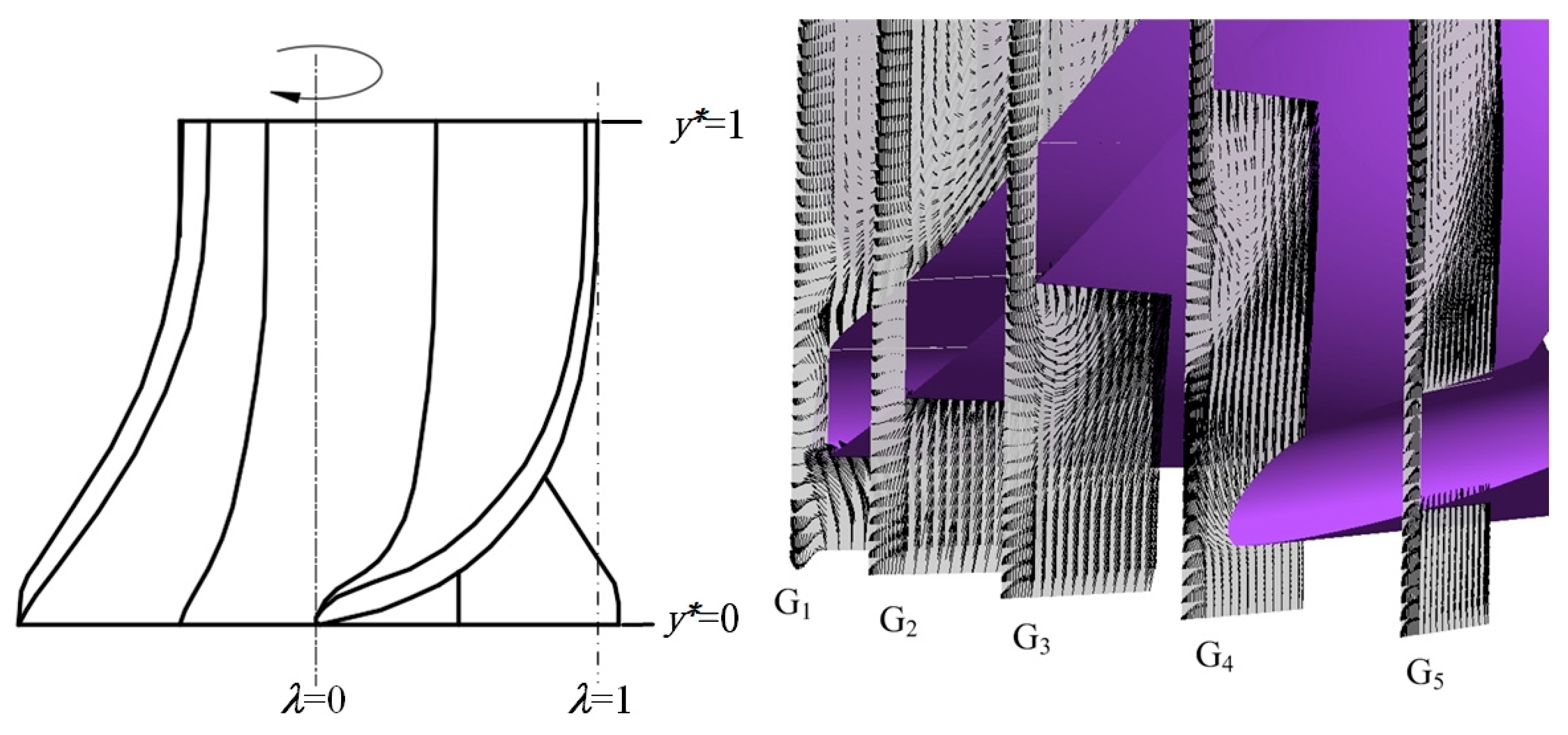
4.1. Structure of Leakage Vortex Flow Field in the Tip Clearance of Composite Impeller Blades

The tip leakage flow is generated by the relative motion between the impeller and the guide ring, combined with the pressure difference before and after the tip of the blade. This leakage flow intersects with the mainstream of the suction surface of the blade to form the tip clearance vortex. Such a leakage flow at the blade tip can cause serious flow losses. Figure 8 shows the velocity vector distribution across several cross-sections. The chord length coefficient of axial flow cascades is defined as λ. The G1-G5 sections are located in the axial sections with blade chord length coefficients λ = 0.1, 0.3, 0.5, 0.7, and 0.9, respectively. As can be seen in Figure 8, the complex flow in the gap at sections G1 and G2 is based on the shear layer near the blade tip and the separation flow near the blade pressure surface. These vortices in the blade tip gap are related to the unsteady blade tip leakage flow velocity, as depicted in the figure. In sections G3 to G5, flow separation mainly occurs near the blade suction surface, and the gap leakage vortices vary with the flow velocity distribution in the blade tip gap.
In order to gain a deeper understanding of the structure of the tip leakage vortex, Figure 9 presents the vorticity distribution and vortex intensity (VSS) distribution at sections G1 to G4. The ordinate r* = 2rD−1 represents the dimensionless radial position of the blade, where r represents the radial position in the impeller and D is the impeller diameter. As shown in Figure 9a, the G1 section is located at the inlet of the impeller. The incoming flow impacts the suction surface (SS) of the blade, causing the fluid at the outer edge of the blade to shift towards the gap. Under the action of wall shear force, reflux occurs at the bottom of the SS, forming the first separated corner vortex (A). Due to the pressure difference between the blade pressure surface (PS) and the suction surface (SS), the fluid at the top of the blade enters the gap and forms a leakage flow. After the leakage flow enters the gap, due to the presence of a right angle at the top of the blade, flow separation occurs at the corner near the PS, forming a second separated corner vortex (B). In Figure 9b, separated vortex A has detached, while separated vortex B propagates into adjacent channels through gaps. The resultant leakage flow forms a jet shear layer under the action of wall shear force, producing a banded negative vorticity region (C). In Figure 9c, after the leakage flow passes through the jet shear layer C, it interacts with the mainstream, initiating the detachment of the separation vortex B from the SS of the blade. As the leakage vortex shedding occurs in Figure 9d, the strength of the vortex decreases, while its range continues to expand.
The axial coefficient σ* within the clearance is defined to analyze the flow field characteristics at different axial positions within the blade tip clearance, as shown in Figure 10. The coordinate begins at the suction surface and spans across the blade thickness. Figure 11 visualizes the turbulent kinetic energy and axial velocity distribution within the blade tip gap at section G3. The distribution of turbulent kinetic energy within the blade tip gap indicates that as the axial coefficient increases near the blade tip, the turbulent kinetic energy first decreases and then increases, reaching a minimum at σ* = 0.7. In other areas of the gap, the distribution of turbulent kinetic energy increases with the rise in axial coefficient. The axial velocity distribution in Figure 11 reveals that the axial velocities within the gap are negative, indicating reverse flow direction relative to the mainstream. The magnitude of the axial velocity within the clearance first increases and then decreases. As the axial coefficient increases, the axial velocity at the blade edge also shows a trend of first decreasing and then rising.

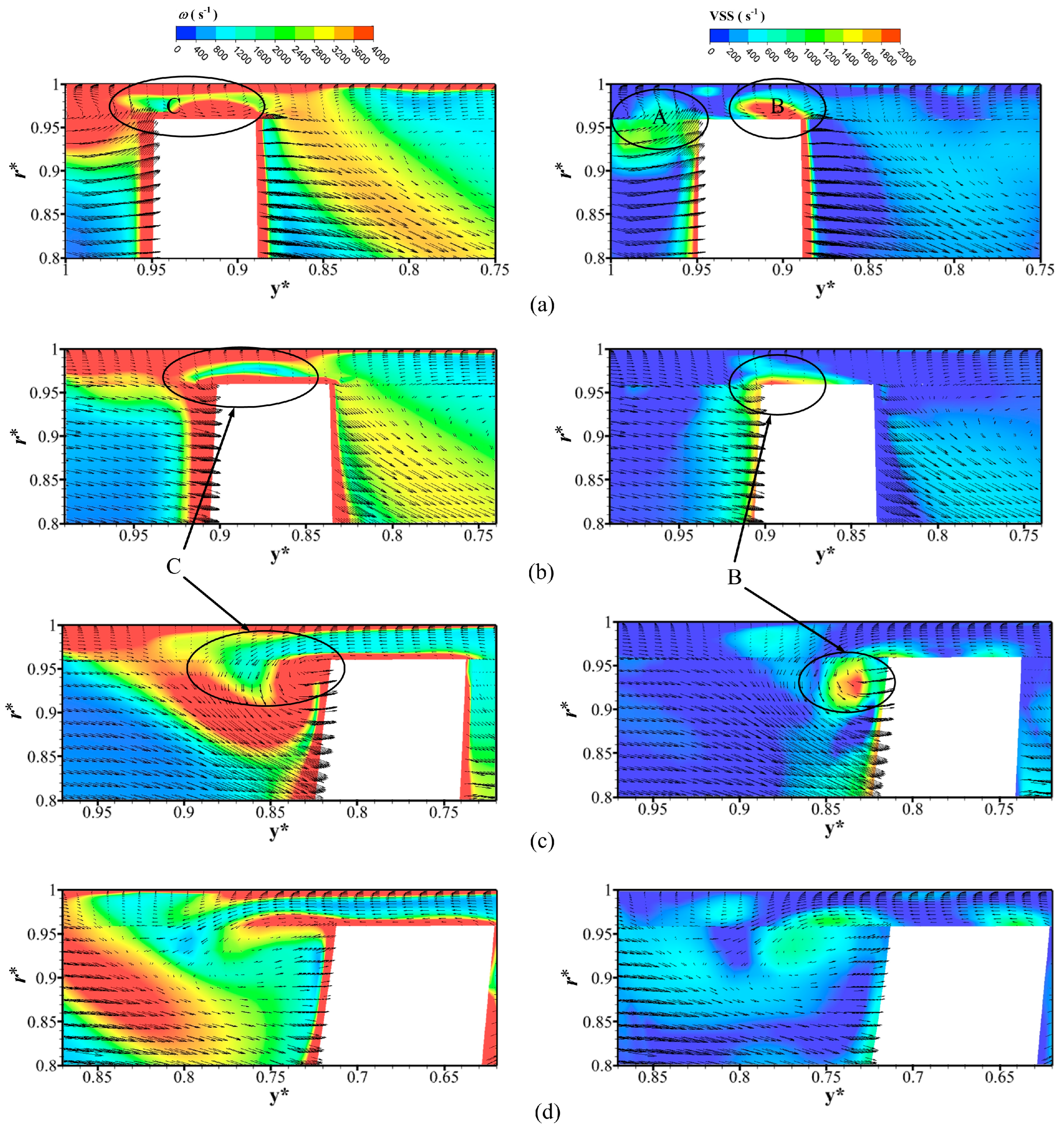
4.2. Evolution of Tip Clearance Vortices in Axial Flow of Composite Impellers

In this research, vortex analysis is carried out using the Q-criterion vortex recognition method, which was first proposed by Hunt et al. [24]. The Q-criterion is based on the decomposition of the velocity gradient tensor. The velocity gradient tensor can be decomposed into a symmetric tensor and an antisymmetric tensor, which represent the deformation and rotation of the fluid, respectively.
The equation of the velocity gradient tensor is as follows:
λ 3 P λ 2 + Q λ R = 0
where λ is the eigenvalue of this characteristic equation; P, Q, and R are the three invariants of the velocity gradient tensor.
To better understand the structural characteristics of the tip leakage vortex (TLV) and the shed vortex (SV), numerical simulations are carried out to capture the transient evolution process of TLV and SV, as shown in Figure 12. The vortex structure is an isosurface with Q = 1 × 10⁴. The trajectory of the tip clearance vortex at the axial flow blade at a continuous time is shown in the figure. The gap leakage vortex caused by blade tip clearance can be divided into two main parts: the initial leakage vortex (PTLV) in the flow channel and the secondary leakage vortex (STLV) in the blade tip clearance area. The former exhibits a tubular structure, while the latter represents a strip-shaped vortex. The gap leakage flow is greatly influenced by the main flow in the channel near the edge of the blade inlet. As a result, the flow velocity of the gap leakage flow gradually increases in the gap area. However, after the leakage flow exits the gap and during the formation of the vortex, the velocity of the vortex decreases due to energy dissipation.
Figure 13 shows a schematic diagram of the development of the tip clearance vortex. The evolution of the clearance leakage vortex can be characterized by three distinct stages. In the first stage, the initial leakage vortex is divided into two parts, namely PTLV-A and PTLV-B. PTLV-A is generated at the outer edge of the blade inlet and develops backward along the rotational direction, while PTLV-B is generated within the inlet clearance of the impeller and develops upwards along the suction direction of the blade. As the impeller rotates, part of the leakage flow enters the lower blade channel, generating secondary leakage vortices STLV. These vortices continuously accumulate and stretch, resulting in a large number of vortex structures accumulated on the suction surface. In the final stage, as the curvature of the blade decreases, the vortices attached to the suction surface of the blade begin to stall and detach. Under the influence of the main flow, the separation point of the stall vortex moves upwards, and the detachment point on the adjacent blade pressure surface moves towards the blade edge and tail direction. As the stalled vortex continues to move upwards, it evolves into a vortex in the transition section.
The Euler head (LEH) is defined as the ratio of the product of the circumferential velocity u (m/s) at a given location in the flow field and the circumferential component vu of the absolute velocity to the gravitational acceleration. According to Euler’s theory, the Euler head is primarily governed by the absolute liquid flow angle at the impeller inlet and outlet, serving as a basis to analyze the transfer and loss of energy in the flow channel [25,26]. The Euler lift can be expressed as follows:
L E H = u v u g
Figure 14a shows the vector and local Euler head at λ = 0.1 of the blade. The area with high energy loss can be seen at λ = 0.3, mainly located at the gap above the blade pressure surface, within the axial region of y* = 0.7 to y* = 0.85, and in the radial region of r* > 0.95. Figure 14b shows the vector diagram and Euler head cloud map of the axial flow blade tip clearance at λ = 0.3. In the regions with high Euler head, as the blade moves upwards, the Euler head value in the blade tip clearance significantly increases. Vortex B reaches the suction surface of the blade under the action of the leakage jet, which is the starting point of vortex B detachment. Reverse flow can be seen at the gap, with the vortex core located at the top of the suction surface. Figure 14c illustrates the vector diagrams and distribution of the Euler head at the blade tip gap λ = 0.5. The region with high Euler head is consistent with the position of jet shear zone C, further indicating that the leaking jet is the main cause of energy loss. The gap leakage vortex B continues to develop, while the low-speed zone continues to expand. The vortex core begins to detach from the suction surface and extend into the flow channel. Figure 14d depicts the axial section at the tip clearance λ = 0.7. With the detachment of the clearance leakage vortex B, the region with high Euler head reaches the bottom of the suction surface and extends into the radial region r* < 0.95 inside the flow channel. Figure 14e shows the vector and Euler head at the tip clearance λ = 0.9. The shedding vortex continues to propagate into the flow channel, expanding the area with a high Euler head.

4.3. Evolution Mechanism of Axial Clearance Vortices in Composite Impellers

Due to the rotational motion of the impeller, the tip clearance vortex primarily develops along the circumferential direction. Accordingly, this article analyzes the generation and evolution of vorticity in the cylindrical coordinate system, as shown in Figure 15. The radial, circumferential, and axial vortices are denoted by ωr, ωθ, and ωy, respectively.
To analyze the influence of tip leakage vortex distribution on various components of vorticity, Figure 16 shows the Q-criterion and the distributions of radial vorticity ωr, circumferential vorticity ωθ, and axial vorticity ωy at the surface locations of r* = 0.95, r* = 0.90, and r* = 0.80. r* = 0.95 is located at the top of the blade, as shown in Figure 16. The initial leakage vortex, PTLV-B, and two shedding vortices can be identified from the Q-criterion cloud map, designated as SV-A and SV-B, respectively. PTLV-B forms a strip-shaped vortex structure from the leading edge to the middle of the blade. As shown in Figure 16, the distribution of ωr reveals a negative vorticity zone that is formed at the front edge of the blade pressure, representing a recirculation zone formed by the interaction between the impeller inflow and the pressure surface. The region with positive vorticity distribution of ωr appears in the area between PTLV-B and the recirculation zone, formed by the interference between leakage flow and recirculation. Since PTLV-B is formed by the leakage flow at the top of the blade and the main flow entrainment, it extends and continuously rotates backwards along the circumferential direction in the flow channel. As a result, a region of high circumferential vorticity (ωθ) forms at the vortex center of PTLV-B, and the high circumferential vorticity distribution area is consistent with the Q-criterion distribution. Due to the shear effect of the guide ring wall, a large area of negative ωy values is observed on the surface of r* = 0.95, indicating that the axial vorticity has a significant impact on the gap leakage vortex. The SSTLV region formed a positive ωy value region opposite to the wall shear. On the surface of r* = 0.90, the dominant flow structures include shedding vortices SV and stall vortex structures. The vorticity in all directions of the leakage flow on the suction surface of the blade is no longer obvious. The high vorticity areas of ωy and ωθ are distributed at SV, while the high vorticity areas of ωr are distributed around SV. When the spanwise coefficient is reduced to r* = 0.80, the stall vortex on the surface is mainly caused by the detachment of the blade suction surface. The influence of ωr is relatively small, while the high vorticity regions of ωy and ωθ are consistent with the position of the stall vortex, indicating that the stall vortex is mainly axial and circumferential.
The intensity of dimensionless pressure fluctuations is quantified by the root mean square (RMS) method as follows [27]:
p ¯ = 1 N i = 1 N p i
p ¯ = 1 N i = 1 N ( p i p ¯ )
I P F = p ¯ 1 / 2 ρ U 2 2
where p ¯ is the arithmetic mean pressure; N is the number of time samples; pi is the pressure at each time step; and p ¯ is the intensity of pressure fluctuations. The pressure fluctuation intensity is then non-dimensionalized using Equation (8) to obtain the IPF.
Figure 17 presents a comparison of pressure fluctuation intensities at different blade extensions from the inlet to the outlet in the impeller channel. The horizontal axis represents the distribution of pressure fluctuation intensity from the blade suction surface to the pressure surface at different chord lengths, while the vertical axis indicates the pressure fluctuation intensity value. The spanwise positions are defined as follows: r* = 0.1 is located at the hub, r* = 0.5 is located in the middle channel, and r* = 0.9 is located at the wheel flange. Figure 17 compares the intensity of pressure fluctuations at these three different positions and their development patterns at different chord lengths. According to the graph, at λ = 0.1, which corresponds to the inlet of the impeller, the highest pressure fluctuation changes from the suction surface to the pressure surface in the flow channel are observed. The pressure fluctuation distribution at the wheel flange is significantly different from that at the hub and the middle flow channel. This difference originates from the intense gap flow at the inlet of the flow channel, indicating that the leakage vortex at the wheel flange has a significant impact on the pressure fluctuation. As the fluid develops upwards, the pressure fluctuations inside the channel gradually diminish. However, due to the leakage vortex still developing at λ = 0.3 and λ = 0.5, the distribution pattern of pressure fluctuations at the shroud remains opposite to the patterns at the hub and middle channel. When the fluid reaches λ = 0.7, the leakage vortex has detached. It can be observed that the pressure fluctuation on the suction surface is higher than that on the pressure surface and consistent with the hub and intermediate flow channel.

5. Conclusions

In this study, the TLV and the associated energy loss in a novel dishwasher pump were systematically investigated.
(1)
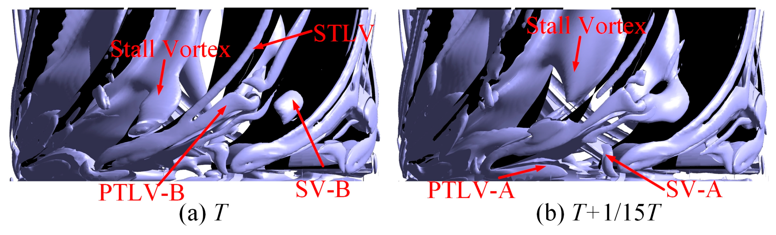
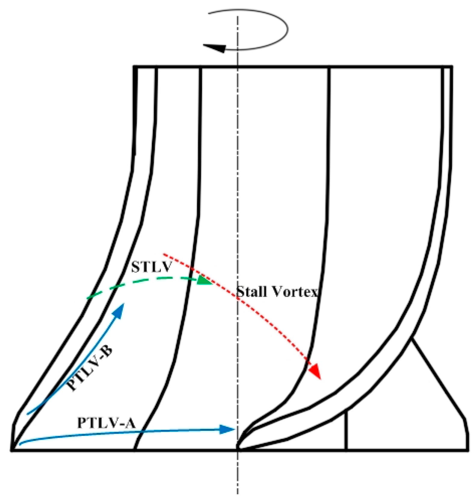
The clearance leakage vortex in a composite axial flow cascade comprises an initial leakage vortex and a secondary leakage vortex. The initial leakage vortex is further divided into two components: corner vortex A, which originates at the outer edge of the blade inlet and progresses backward along the direction of rotation, and corner vortex B, which emerges within the impeller inlet clearance and ascends along the suction side of the blade. As a portion of the leakage flow enters the flow passage of the subsequent stage blades due to the impeller’s rotation, secondary leakage vortices are formed. These vortices progressively accumulate and stretch within the flow passage, ultimately inducing stall and detachment along with the vortices adhering to the suction side of the blade, before finally reaching the pressure side of adjacent blades.
(2)
The leakage vortex within the tip clearance of the blades in the flow passages evolves from the suction side of the blade towards the center of the flow passage. It ultimately detaches and impacts the pressure side of the adjacent blade. The vorticity distribution across the eight flow passages in the impeller demonstrates a predominantly axisymmetric characteristic. Additionally, the double-tongue volute structure influences the flow field within the bottom axial flow cascade.
(3)
The trajectory of the shedding vortex (SV) exhibits a notable correlation with vorticity in various directions. The distribution of radial, circumferential, and axial vorticity across different radial heights reveals that the vorticity at the SV generation site is predominantly contributed by the circumferential and axial vorticity components, with the circumferential vorticity being dominant. As the detached SV migrates through the flow channel, the circumferential vorticity contribution gradually diminishes.
(4)
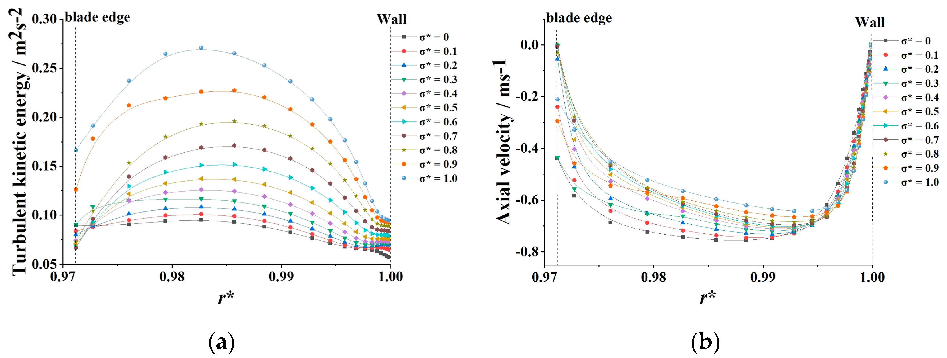
The energy loss at the inlet of the impeller is greater than at other regions within the flow passage. The region of energy loss adjacent to the suction surface of the shroud coincides with the area occupied by the leakage vortex, indicating that the oscillation and shedding of the tip leakage vortex are key contributors to localized energy loss within the flow passage.

Author Contributions

Conceptualization, C.N.; methodology, C.N. and Y.L.; software, C.N., H.S. and Y.W.; validation, C.N., Y.L. and Y.W.; formal analysis, C.N. and Y.L.; investigation, C.N. and Y.W.; resources, C.N. and H.S.; data curation, C.N. and H.S.; writing—original draft preparation, C.N.; writing—review and editing, C.N., H.S. and Y.W.; visualization, C.N. and F.M.; supervision, C.N.; project administration, C.N.; funding acquisition, F.M. All authors have read and agreed to the published version of the manuscript.

Funding

This research was funded by the Changzhou Science and Technology Project (grant number CJ20235074). The Open Research Subject of Key Laboratory of Fluid Machinery and Engineering (Xihua University), Sichuan Province (grant number LTJX-2025003). Science and Technology Program Project of Taizhou (grant number 24gyb61).

Data Availability Statement

Data is contained within the article.

Conflicts of Interest

Author Yue Wang was employed by the Machinery Technology Development Co., Ltd. The remaining authors declare that the research was conducted in the absence of any commercial or financial relationships that could be construed as a potential conflict of interest.

References

  1. Zhu, Y.L.; Zhang, J.F.; Li, Y.L.; Huang, P.; Xu, H.; Zheng, F. Experimental investigation of unsteady pressure pulsation in new type dishwasher pump with special double-tongue volute. Machines 2021, 9, 288. [Google Scholar] [CrossRef]
  2. Zhang, J.F.; Zhu, Y.L.; Li, Y.L.; Huang, P.; Xu, H.; Zheng, F. Investigation of unsteady pressure pulsation in new type dishwasher pump with special double tongue volute. Shock. Vib. 2022, 9, 9349432. [Google Scholar] [CrossRef]
  3. Li, Y.; Sun, H.; Xu, H.; Wang, X.; Li, Y. Orthogonal optimization design of the compound impeller for a New Type of dishwasher pump. Processes 2022, 10, 1813. [Google Scholar] [CrossRef]
  4. Ning, C.; Li, Y.L.; Huang, P.; Xu, H.; Zheng, F. Numerical analysis of a new type of dishwasher pump for different rotation speeds of the volute. Front. Energy Res. 2022, 9, 825159. [Google Scholar] [CrossRef]
  5. Zhang, H.; Zang, J.; Zhang, D.; Shi, W.; Shen, J. Analysis of the Formation Mechanism of Secondary Tip Leakage Vortex (S-TLV) in an Axial Flow Pump. Machines 2022, 10, 41. [Google Scholar] [CrossRef]
  6. Li, W.; Ji, L.; Shi, W.; Li, E.; Yang, Z. Particle image velocimetry measurement of flow fields in a mixed-flow pump with non-uniform tip clearance. J. Vis. 2021, 24, 29–45. [Google Scholar] [CrossRef]
  7. Li, W.; Ji, L.; Li, E.; Zhou, L.; Agarwal, R.K. Effect of tip clearance on rotating stall in a mixed-flow pump. J. Turbomach. 2021, 143, 091013. [Google Scholar] [CrossRef]
  8. Yu, L.; Cheng, L.; Xu, W.; Lei, S. Study on the influence of tip clearance on cavitation performance and entropy production of an axial flow pump. J. Mar. Sci. Eng. 2024, 12, 101. [Google Scholar] [CrossRef]
  9. Wen, H.; Li, L.; Shi, G.; Ma, H.; Peng, X. Effect of tip clearance on force characteristics of helical axial-flow blade pumps under cavitation conditions. J. Mar. Sci. Eng. 2023, 11, 2299. [Google Scholar] [CrossRef]
  10. Wen, H.; Lv, W.; Shi, G. Study of Tip Clearance on Dynamic and Static Head of a Spiral Axial-Flow Blade Pump under Cavitation Conditions. Water 2023, 15, 4304. [Google Scholar] [CrossRef]
  11. Shen, X.; Wu, H.; Yang, G.; Tang, R.; Chang, C.; Xu, B.; Lin, S.; Zhang, D. Experimental study on the classification and evolution of the tip cavitation morphology in axial waterjet pumps with two different blade numbers. J. Mar. Sci. Eng. 2024, 12, 1898. [Google Scholar] [CrossRef]
  12. Tang, X.; Jiang, W.; Zhang, Y.; Li, Y.; Wang, Y.; Chen, D. Effect of tip clearance flow on pressure oscillation and vortex patterns of a high-speed centrifugal pump. Proc. Inst. Mech. Eng. Part C J. Mech. Eng. Sci. 2024, 238, 822–836. [Google Scholar] [CrossRef]
  13. Guo, X.; Jiang, C.; Qian, H.; Zhu, Z. The influence of tip clearance on the performance of a high-speed inducer centrifugal pump under different flow rates conditions. Processes 2023, 11, 239. [Google Scholar] [CrossRef]
  14. Zhang, W.P.; Shi, L.J.; Tang, F.P.; Sun, Z.-Z.; Zhang, Y. Identification and analysis of the inlet vortex of an axial-flow pump. J. Hydrodyn. 2022, 34, 234–243. [Google Scholar] [CrossRef]
  15. Li, Y.; Lin, Q.; Meng, F.; Zheng, Y.; Xu, X. Research on the influence of tip clearance of axial-flow pump on energy characteristics under pump and turbine conditions. Machines 2022, 10, 56. [Google Scholar] [CrossRef]
  16. Qian, B.; Cai, Y.; Ding, Q.; Zhao, D.; Sun, W.; Wang, L. Investigation of tip leakage vortex structure and trajectory in a centrifugal pump with a new omega vortex identification method. Appl. Sci. 2022, 12, 5270. [Google Scholar] [CrossRef]
  17. Kan, K.; Zhang, Q.; Xu, Z.; Zheng, Y.; Gao, Q.; Shen, L. Energy loss mechanism due to tip leakage flow of axial flow pump as turbine under various operating conditions. Energy 2022, 255, 124532. [Google Scholar] [CrossRef]
  18. Rafiee, S.E.; Grnman, A.; Uusitalo, A.; Turunen-Saaresti, T. Comprehensive study on the design and analysis of supercritical carbon dioxide (sCO2) radial outflow turbines (ROTs), focusing on tip clearance effects, loss correlations, and performance evaluation. Appl. Therm. Eng. 2025, 272, 126399. [Google Scholar] [CrossRef]
  19. Liu, H.; Tang, F.; Shi, L.; Dai, L.; Shen, J.; Liu, J. The Analysis of Cavitation Flow and Pressure Pulsation of Bi-Directional Pump. J. Mar. Sci. Eng. 2023, 11, 268. [Google Scholar] [CrossRef]
  20. Ji, L.; Li, S.; Li, W.; Huang, Y.; Shi, W.; Li, H.; Yang, Y.; Agarwal, R.K. Study on passive suppression method of rotating stall in mixed-flow pump: Using different impeller rim structures. Proc. Inst. Mech. Eng. Part A J. Power Energy 2023, 237, 965–984. [Google Scholar] [CrossRef]
  21. Shen, J.; Xu, F.; Cheng, L.; Pan, W.; Ge, Y.; Li, J.; Zhang, J. Simulation of internal flow characteristics of an axial flow pump with variable tip clearance. Water 2022, 14, 1652. [Google Scholar] [CrossRef]
  22. Wang, L.; Tang, F.; Liu, H.; Zhang, X.; Sun, Z.; Wang, F. Investigation of cavitation and flow characteristics of tip clearance of bidirectional axial flow pump with different clearances. Ocean Eng. 2023, 288, 115960. [Google Scholar] [CrossRef]
  23. Miorini, R.L.; Wu, H.X.; Katz, J. The internal structure of the tip leakage vortex within the rotor of an axial waterjet pump. J. Turbomach. 2012, 134, 031018.1–031018.12. [Google Scholar] [CrossRef]
  24. Hunt, J.; Wray, A.; Moin, P. Eddies, Stream, and Convergence Zones in Turbulent Flows; Center for Turbulent Research Report CTR-S8; Center for Turbulence Research: Stanford, CA, USA, 1988; pp. 193–208. [Google Scholar]
  25. Yan, P.; Chu, N.; Wu, D.Z.; Cao, L.; Yang, S.; Wu, P. Computational fluid dynamics-based pump redesign to improve efficiency and decrease unsteady radial forces. J. Fluids Eng. Trans. ASME 2017, 139, 011101. [Google Scholar] [CrossRef]
  26. Liu, Y.B.; Tan, L. Spatial-temporal evolution of tip leakage vortex in a mixed-flow pump with tip clearance. J. Fluids Eng. Trans. ASME 2019, 141, 081302. [Google Scholar] [CrossRef]
  27. Tran, B.N.; Jeong, H.; Kim, J.H.; Park, J.-S.; Yang, C. Effects of tip clearance size on energy performance and pressure fluctuation of a tidal propeller turbine. Energies 2020, 13, 4055. [Google Scholar] [CrossRef]
Figure 1. Physical model of a novel dishwasher pump.
Machines 13 00681 g001
Figure 2. Computational domains of the novel dishwasher pump.
Machines 13 00681 g002
Figure 3. Mesh of the novel dishwasher pump.
Machines 13 00681 g003
Figure 4. Grid independence.
Machines 13 00681 g004
Figure 5. Distribution of y+ on the surface of blades.
Machines 13 00681 g005
Figure 6. Measurement system.
Machines 13 00681 g006
Figure 7. Comparison of numerical and experimental results for performance curves of the novel dishwasher pump.
Machines 13 00681 g007
Figure 8. Vector distribution on G1-G5 sections.
Machines 13 00681 g008
Figure 9. Vorticity distribution and vortex intensity distribution in tip clearance at sections (a) G1, (b) G2, (c) G3, (d) G4.
Machines 13 00681 g009
Figure 10. Axial coefficient in clearance.
Machines 13 00681 g010
Figure 11. Distribution of (a) turbulent kinetic energy and (b) axial velocity in tip clearance at section G3.
Machines 13 00681 g011
Figure 12. Trajectory of tip leakage vortices.
Machines 13 00681 g012
Figure 13. Development of tip leakage vortex.
Machines 13 00681 g013
Figure 14. Vector diagrams and local Euler head at G1–G5 sections.
Machines 13 00681 g014
Figure 15. Schematic of cylindrical coordinates.
Machines 13 00681 g015
Figure 16. Distribution of Q criterion, radial vorticity ωr, circumferential vorticity ωθ, and axial vorticity ωy on curved surfaces with different radial coefficients.
Machines 13 00681 g016
Figure 17. Comparison of pressure fluctuation intensities at different blade cross-section in impeller flow channels.
Machines 13 00681 g017
Table 1. Parameters and corresponding design values.
ParametersValue
Design flow rate (Qd)55 L/min
Number of impeller blades (Z)8
Impeller rotating speed (n)3000 rpm
Diameter of inlet (Din)32 mm
Diameter of impeller inlet (D)32 mm
Delivery head (H)1.5 m
Diameter of outlet (Dout)40 mm
Table 2. Grid number of five different grid schemes.
Grid SchemesN1N2N3N4N5
Grid number
(106)
7.738.759.8311.3413.37
Table 3. Simulation parameters.
ItemClassificationSetupValue
ModelTurbulent modelStandard k-ε-
Physical characteristicsWaterdensity998 kg/m3
dynamic viscosity0.001 kg/(m·s)
Initial conditionInletMass flow rate55 L/min
Turbulence intensity5%
OutletOutflow-
Turbulence intensity5%
WallNo slip-
Disclaimer/Publisher’s Note: The statements, opinions and data contained in all publications are solely those of the individual author(s) and contributor(s) and not of MDPI and/or the editor(s). MDPI and/or the editor(s) disclaim responsibility for any injury to people or property resulting from any ideas, methods, instructions or products referred to in the content.

