


Superiority of Fault-Caused-Speed-Fluctuation-Based Dynamics Modeling: An Example on Planetary Gearbox with Cracked Sun Gear

Abstract
1. Introduction
- (a)
- The meshing stiffness of the cracked sun gear is deduced by the potential energy method, which is represented by the rotational angle of the sun gear. Therefore, fault-caused speed fluctuation is creatively integrated into the meshing stiffness by integrating the rotation speed to obtain the rotational angle.
- (b)
- Modal parameters of flexible housing are considered in the transfer path, which highly affects the transfer path functions and modulation sidebands in resonance ranges.
- (c)
- A rigid-flexible coupling dynamics model of the planetary gear set combines fault-caused speed fluctuation and modal parameters of flexible-housing-affected transfer paths, which perfects the previous dynamics model of the planetary gear set and clearly reveals the vibration AM-FM behavior of the cracked sun gear.
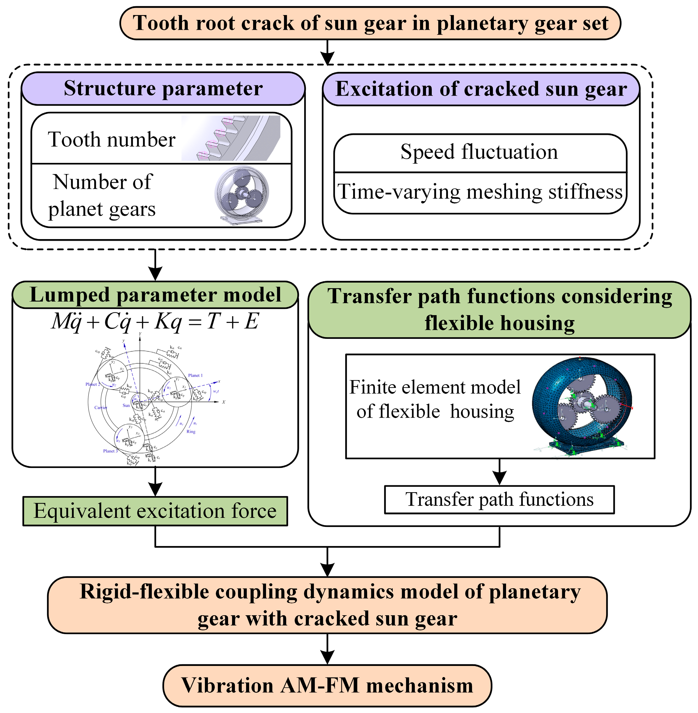
2. Rigid-Flexible Coupling Dynamics Model of Planetary Gear Set with Cracked Sun Gear
- (a)
- Path 1: Meshing force of p-r gear pair acting on ring → flexible housing → sensor.
- (b)
- Path 2: Excitation force acting on the bearing of the sun gear → flexible housing → sensor.
- (c)
- Path 3: Excitation force acting on the bearing of the carrier → flexible housing → sensor.

2.1. LPM Involving Fault-Caused Speed Fluctuation
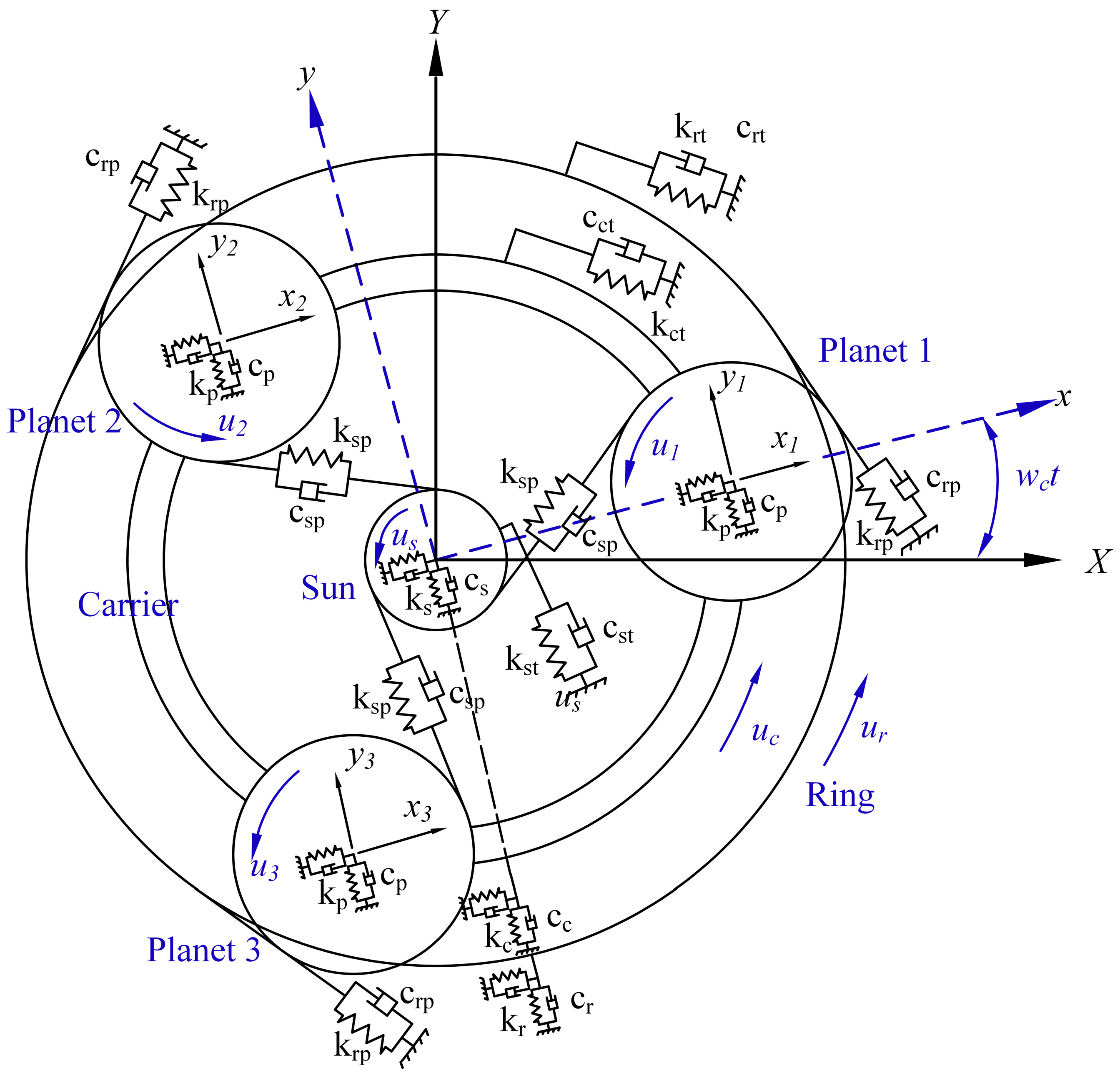
2.1.1. LPM of Planetary Gear Set
2.1.2. Meshing Stiffness Considering Fault-Caused Speed Fluctuation
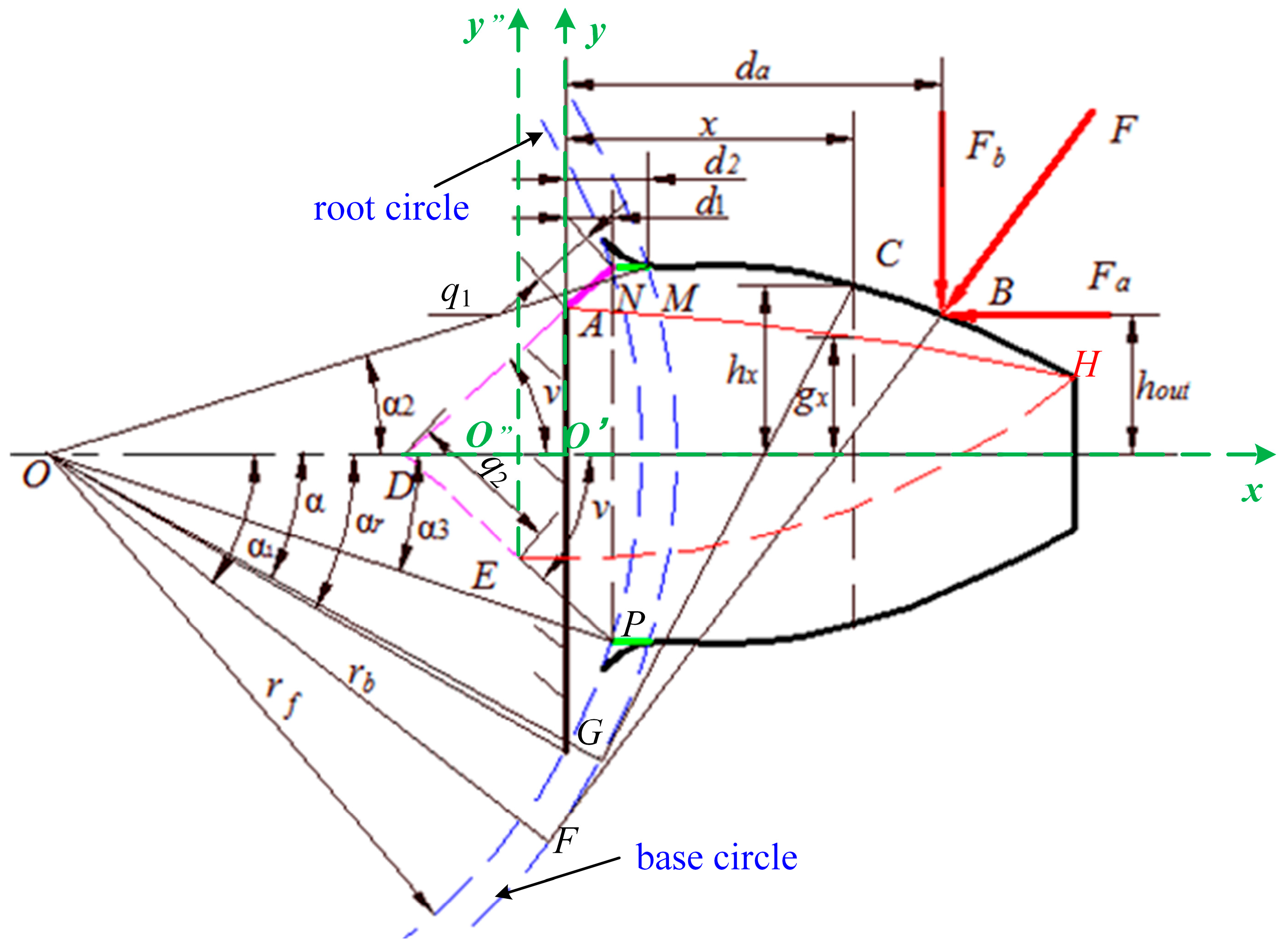
- The meshing stiffness of the cracked sun gear calculated by the potential energy method
- (a)
- Case 1: Small crack without extending to the centerline of the sun gear tooth
- (b) Case 2: large crack extending below the centerline of the sun gear tooth
- (c) Effect of fault-caused speed fluctuation on meshing stiffness of cracked sun gear
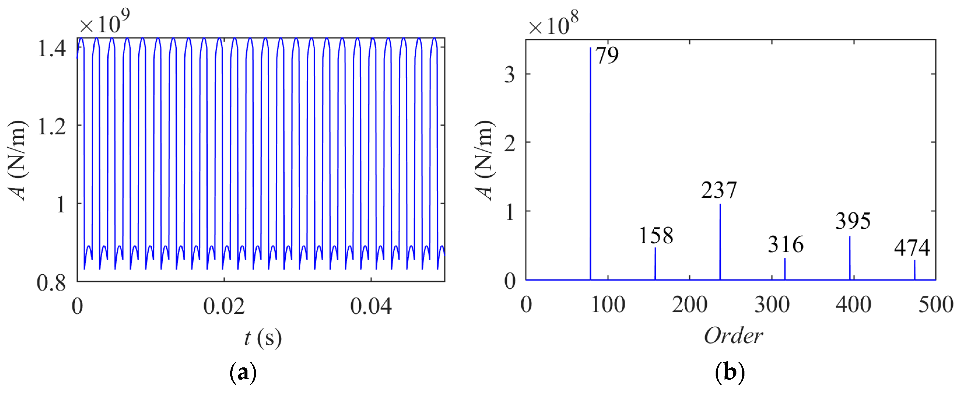
- Meshing stiffness of s-p and p-r gear pairs with cracked sun gear
- Effect demonstration of fault-caused speed fluctuation on meshing stiffness
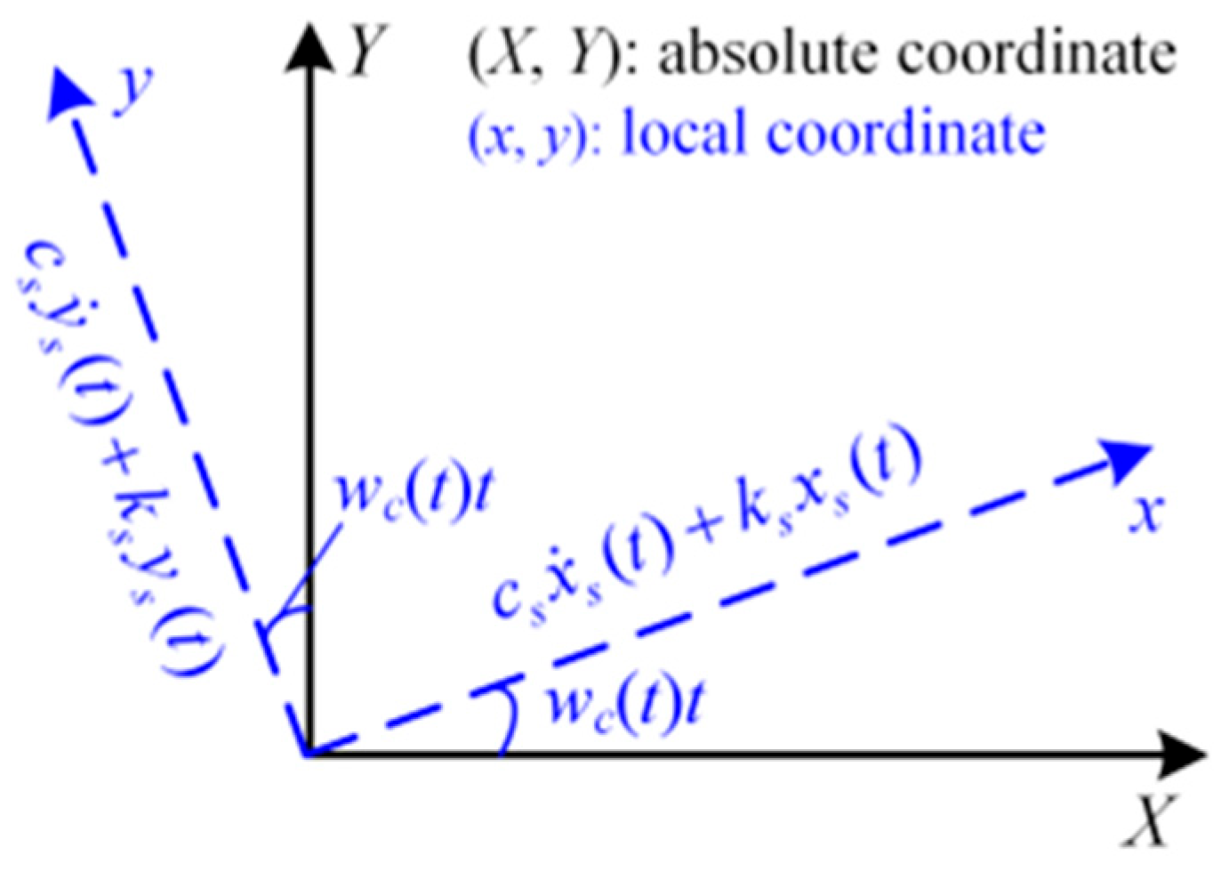
2.1.3. Excitation Forces in Three Paths
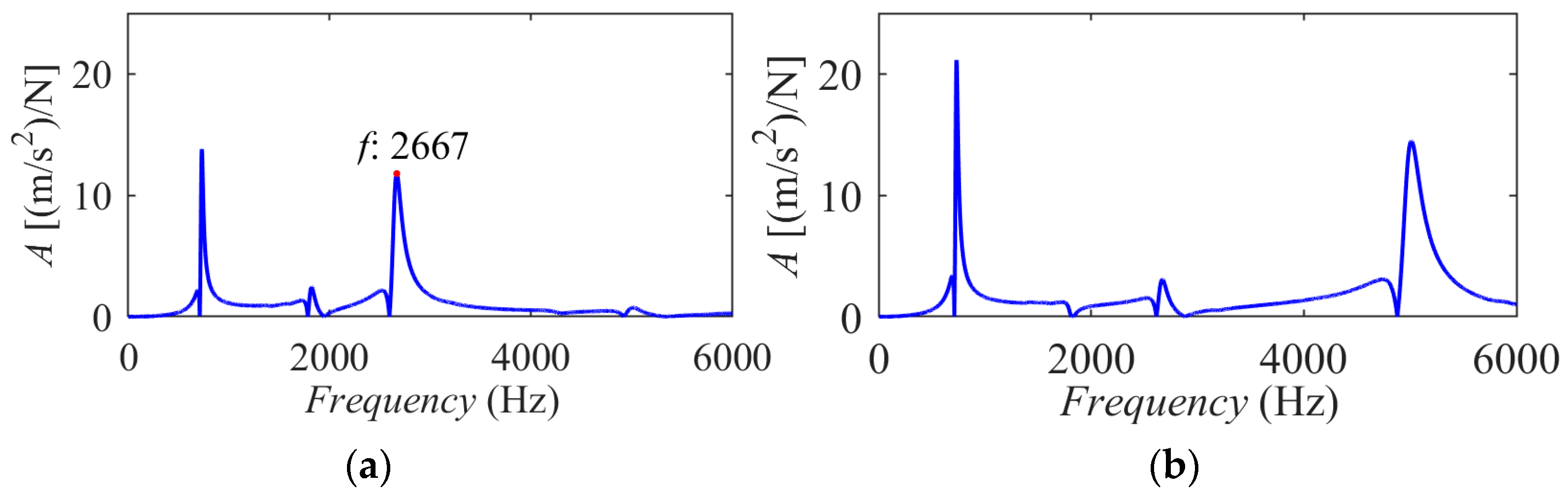
2.2. Transfer Path Functions Considering Modal Parameters of Flexible Housing
3. Resultant Vibration Signal Analysis
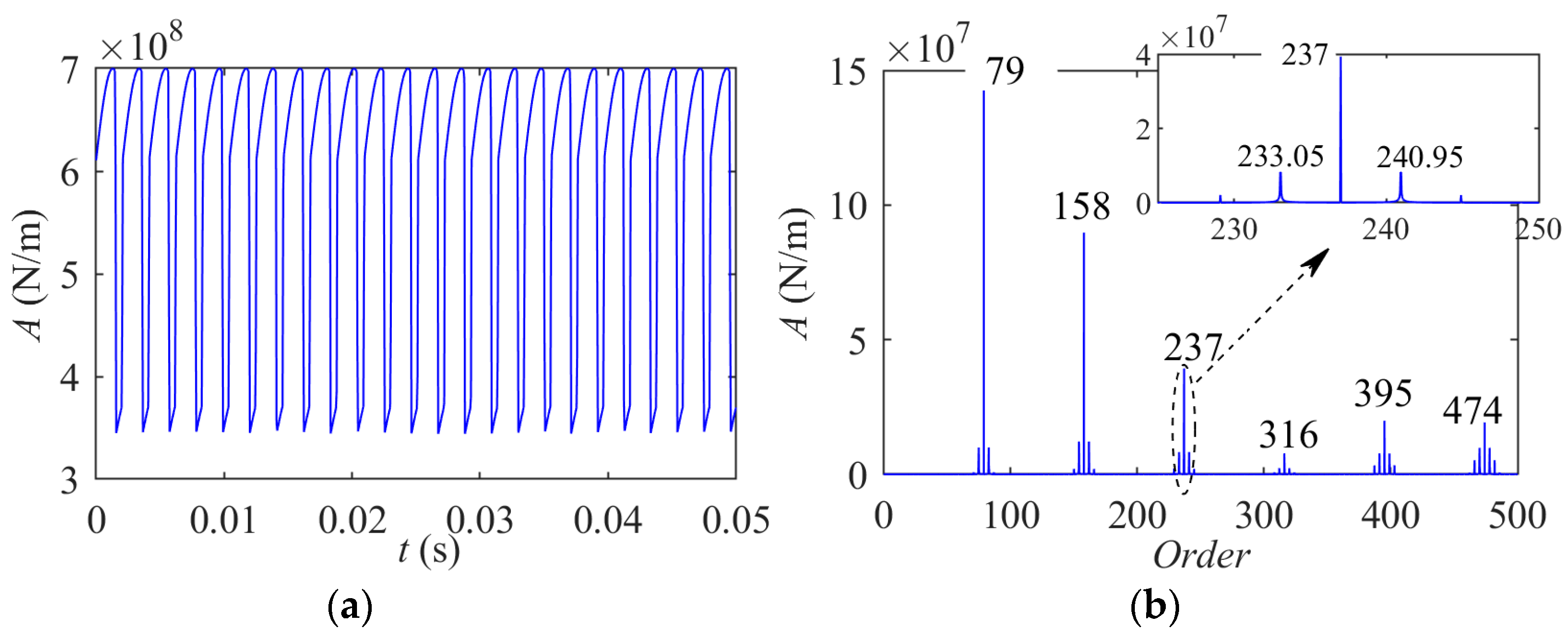
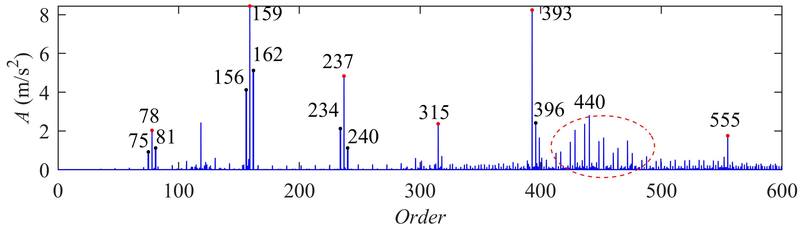
3.1. Tooth Root Crack of Sun Gear Without Considering the Fault-Caused Speed Fluctuation
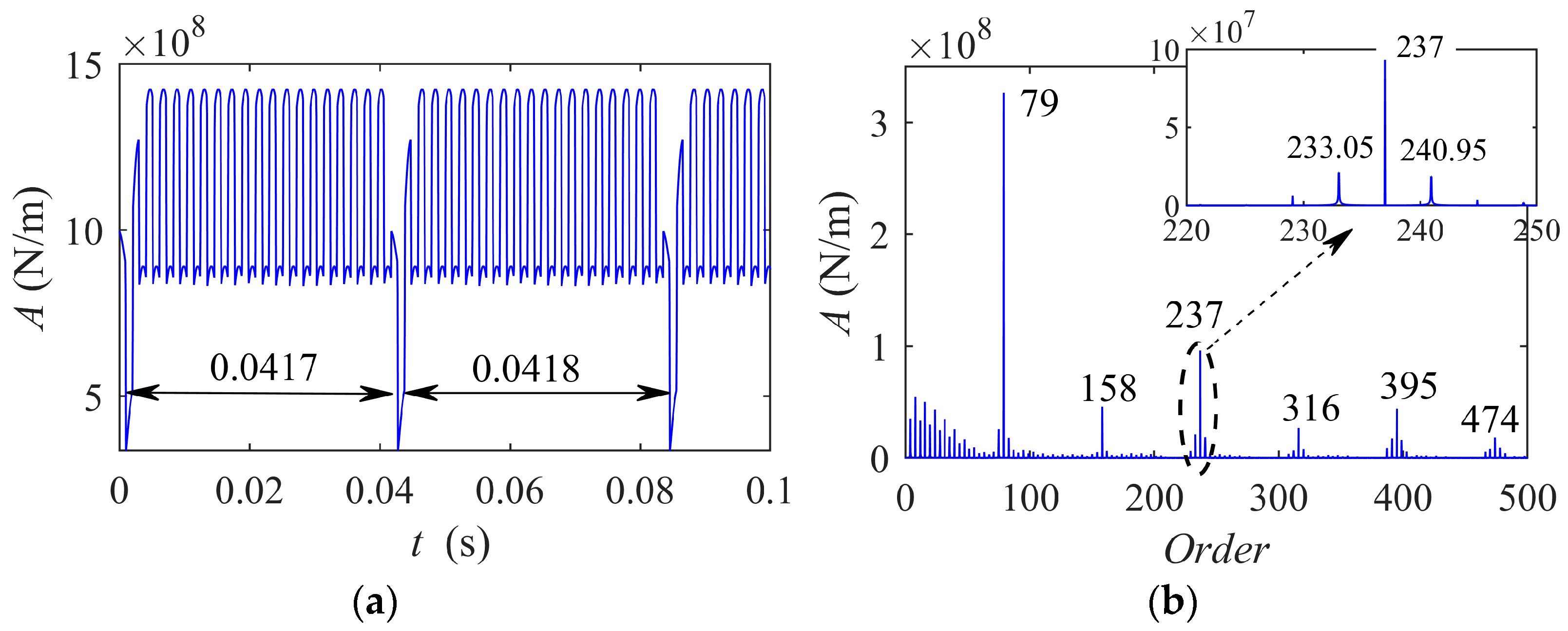
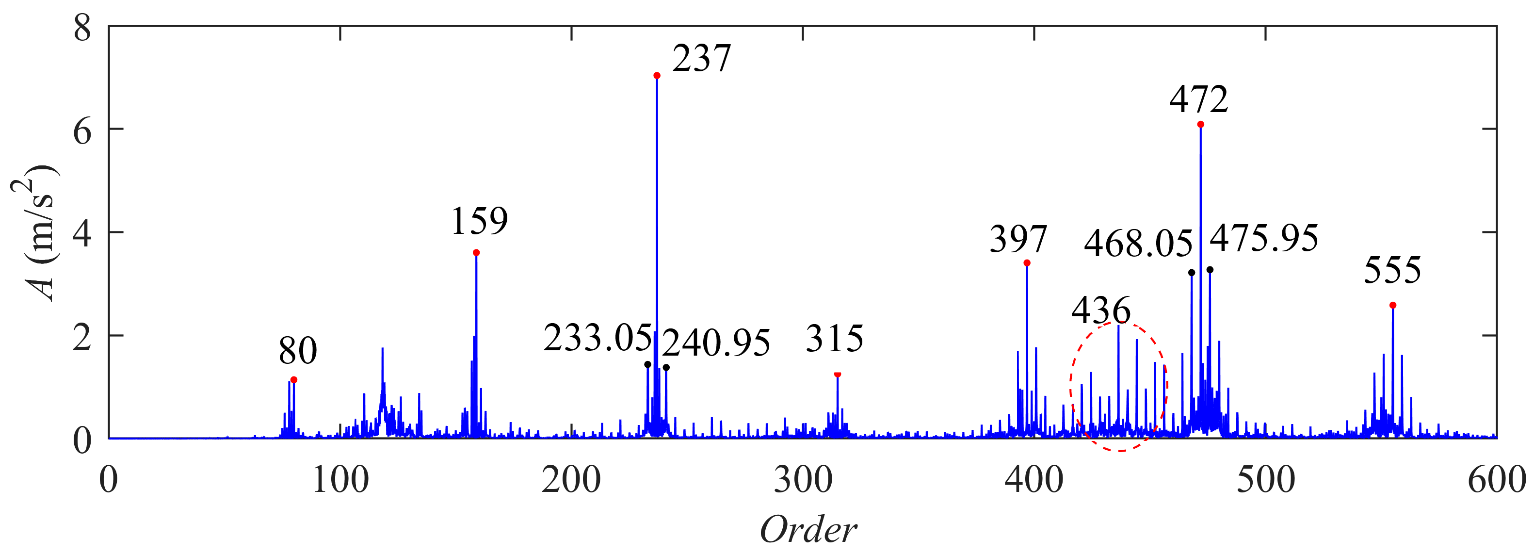
3.2. Tooth Root Crack on Sun Gear Considering the Fault-Caused Speed Fluctuation
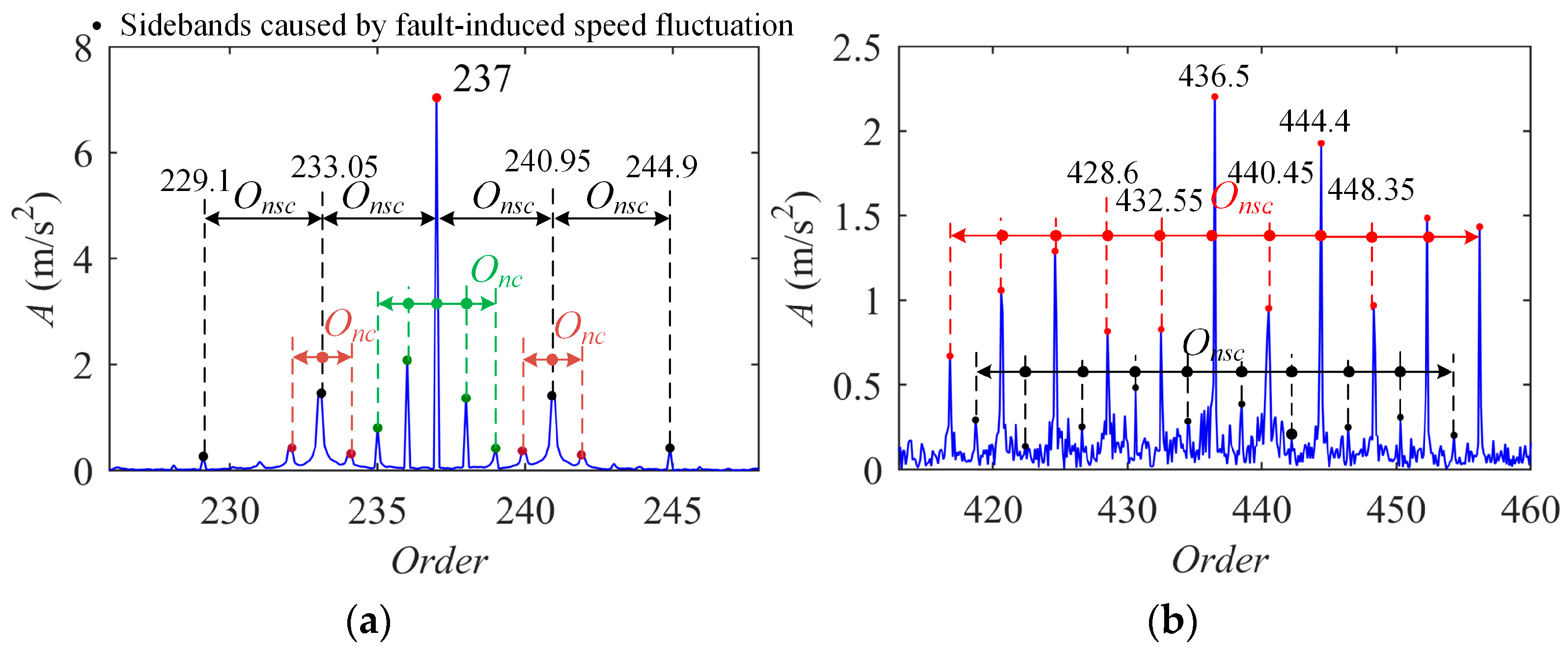
3.3. Vibration AM-FM Sidebands of Cracked Sun Gear
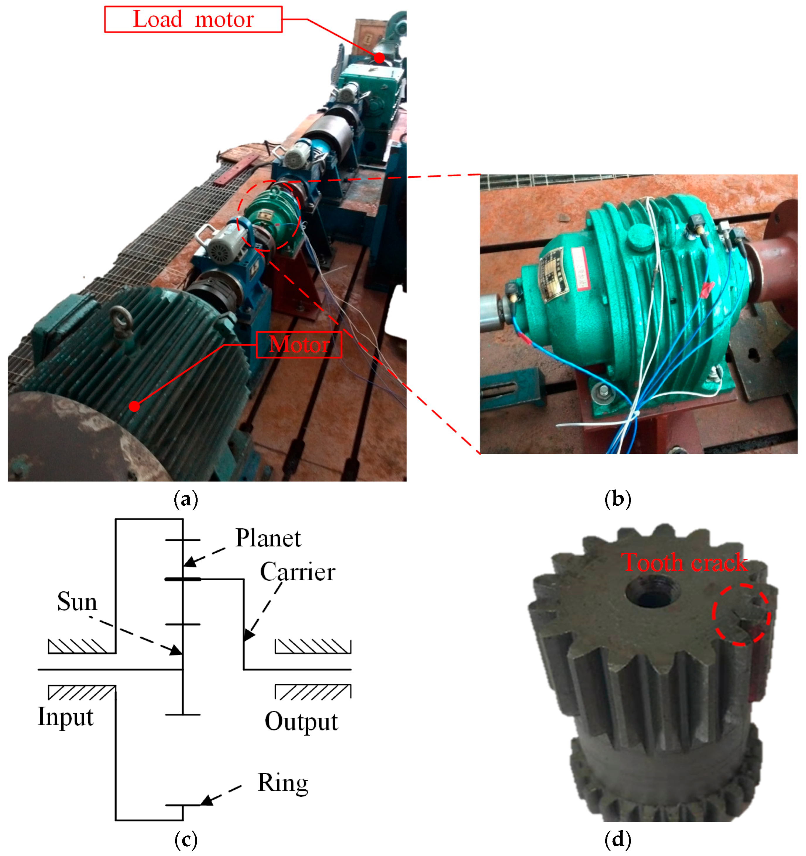
4. Experimental Validation
4.1. Planetary Gearbox with Gear Ratio of 6.18
4.2. Planetary Gearbox with Gear Ratio of 7
5. Conclusions
Author Contributions
Funding
Data Availability Statement
Conflicts of Interest
Abbreviations
| LPM | Lumped parameter model |
| AM | Amplitude modulation |
| FM | Frequency modulation |
| c | Carrier |
| s | Sun gear |
| p | Planet gears |
| r | Ring gear |
References
- Feng, Z.; Gao, A.; Li, K.; Ma, H. Planetary gearbox fault diagnosis via rotary encoder signal analysis. Mech. Syst. Signal Process 2021, 149, 107325. [Google Scholar] [CrossRef]
- Liu, X.; Yang, Y.; Zhang, J. Resultant vibration signal model based fault diagnosis of a single stage planetary gear train with an incipient tooth crack on the sun gear. Renew. Energy 2018, 122, 65–79. [Google Scholar] [CrossRef]
- Shi, J.; Peng, D.; Peng, Z.; Zhang, Z.; Goebel, K.; Wu, D. Planetary gearbox fault diagnosis using bidirectional-convolutional LSTM networks. Mech. Syst. Signal. Process 2022, 162, 107996. [Google Scholar] [CrossRef]
- Cao, P.; Li, Q.; Feng, K.; Qin, Y. Dynamic modeling of spur gear transmission system with evolutive coupling fault of fatigue crack and wear. Eng. Fail. Anal. 2024, 156, 107820. [Google Scholar] [CrossRef]
- Peng, D.; Smith, W.A.; Borghesani, P.; Randall, R.B.; Peng, Z. Comprehensive planet gear diagnostics: Use of transmission error and mesh phasing to distinguish localised fault types and identify faulty gears. Mech. Syst. Signal Process 2019, 127, 531–550. [Google Scholar] [CrossRef]
- Su, H.; Wang, Z.; Cai, Y.; Ding, J.; Wang, X.; Yao, L. Refined Composite Multiscale Fluctuation Dispersion Entropy and Supervised Manifold Mapping for Planetary Gearbox Fault Diagnosis. Machines 2023, 11, 47. [Google Scholar] [CrossRef]
- Dai, H.; Wang, Y.; Luo, S.; Li, Y.; Zi, B. Dynamic modeling and vibration analysis of planetary gear sets concerning mesh phasing modulation. Mech. Syst. Signal Process 2023, 200, 110557. [Google Scholar] [CrossRef]
- Nie, Y.; Li, F.; Wang, L.; Li, J.; Wang, M.; Sun, M.; Li, G.; Li, Y. Phenomenological vibration models of planetary gearboxes for gear local fault diagnosis. Mech. Mach. Theory 2022, 170, 104698. [Google Scholar] [CrossRef]
- Liu, L.; Liang, X.; Zuo, M.J. Vibration signal modeling of a planetary gear set with transmission path effect analysis. Measurement 2016, 85, 20–31. [Google Scholar] [CrossRef]
- Zhang, K.; Li, H.; Cao, S.; Wang, C.; Sun, B.; Liu, A. Investigation on planetary gearbox fault mechanism under variable speed conditions based on rigid-flexible coupling dynamics model. Eng. Fail. Anal. 2022, 133, 105994. [Google Scholar] [CrossRef]
- Lei, Y.; Liu, Z.; Lin, J.; Lu, F. Phenomenological models of vibration signals for condition monitoring and fault diagnosis of epicyclic gearboxes. J. Sound Vibrat. 2016, 369, 266–281. [Google Scholar] [CrossRef]
- Liu, Z.; Lei, Y.; Liu, H.; Yang, X.; Song, W. A phenomenological model for investigating unequal planet load sharing in epicyclic gearboxes. Mech. Syst. Signal Process 2020, 135, 106414. [Google Scholar] [CrossRef]
- Xu, L.; Ding, K.; He, G.; Li, Y.; Chen, Z. Resonance modulation vibration mechanism of equally-spaced planetary gearbox with a localized fault on sun gear. Mech. Syst. Signal Process 2022, 166, 108450. [Google Scholar] [CrossRef]
- Chen, Z.G.; Zhou, Z.W.; Zhai, W.M.; Wang, K.Y. Improved mesh stiffness calculation model of spur gear pair with tooth profile deviations. Mech. Mach. Theory 2020, 149, 103838. [Google Scholar] [CrossRef]
- Yang, Y.; Hu, N.; Cheng, Z.; Hu, J.; Zhang, L. Improved Mesh Stiffness Method and Vibration Analysis of a Planetary Gear System with a Spatial Tooth Crack. Machines 2022, 10, 1168. [Google Scholar] [CrossRef]
- Yang, Y.; Hu, N.; Li, Y.; Cheng, Z.; Shen, G. Dynamic modeling and analysis of planetary gear system for tooth fault diagnosis. Mech. Syst. Signal Process 2024, 207, 110946. [Google Scholar] [CrossRef]
- Natali, C.; Battarra, M.; Dalpiaz, G.; Mucchi, E. A critical review on FE-based methods for mesh stiffness estimation in spur gears. Mech. Mach. Theory 2021, 161, 104319. [Google Scholar] [CrossRef]
- Wang, Q.; Chen, K.; Zhao, B.; Ma, H.; Kong, X. An analytical-finite-element method for calculating mesh stiffness of spur gear pairs with complicated foundation and crack. Eng. Fail. Anal. 2018, 94, 339–353. [Google Scholar] [CrossRef]
- Cooley, C.G.; Liu, C.; Dai, X.; Parker, R.G. Gear tooth mesh stiffness: A comparison of calculation approaches. Mech. Mach. Theory 2016, 105, 540–553. [Google Scholar] [CrossRef]
- Liang, X.; Zuo, M.J.; Pandey, M. Analytically evaluating the influence of crack on the mesh stiffness of a planetary gear set. Mech. Mach. Theory 2014, 76, 20–38. [Google Scholar] [CrossRef]
- Meng, Z.; Shi, G.; Wang, F. Vibration response and fault characteristics analysis of gear based on time-varying mesh stiffness. Mech. Mach. Theory 2020, 148, 103786. [Google Scholar] [CrossRef]
- Chen, Z.; Zhu, Z.; Shao, Y. Fault feature analysis of planetary gear system with tooth root crack and flexible ring gear rim. Eng. Fail. Anal. 2015, 49, 92–103. [Google Scholar] [CrossRef]
- Moshrefzadeh, A.; Fasana, A. Planetary gearbox with localised bearings and gears faults: Simulation and time/frequency analysis. Meccanica 2017, 52, 3759–3779. [Google Scholar] [CrossRef]
- Jiang, F.; Ding, K.; He, G.; Sun, Y.; Wang, L. Vibration fault features of planetary gear train with cracks under time-varying flexible transfer functions. Mech. Mach. Theory 2021, 158, 104237. [Google Scholar] [CrossRef]
- Han, H.; Zhao, Z.; Ma, H.; Yang, Y.; Li, X. Fault feature analysis of planetary gear set influenced by cracked gear tooth and pass effect of the planet gears. Eng. Fail. Anal. 2021, 121, 105162. [Google Scholar] [CrossRef]
- Han, H.; Ma, H.; Tian, H.; Peng, Z.; Zhu, J.; Li, Z. Sideband analysis of cracked planetary gear train considering output shaft radial assembly error. Mech. Syst. Signal Process. 2023, 200, 110618. [Google Scholar] [CrossRef]
- Hu, A.; Liu, S.; Xiang, L.; Zhang, Y. Dynamic modeling and analysis of multistage planetary gear system considering tooth crack fault. Eng. Fail. Anal. 2022, 137, 106408. [Google Scholar] [CrossRef]
- Yang, X.; Ding, K.; He, G. Phenomenon-model-based AM-FM vibration mechanism of faulty spur gear. Mech. Syst. Signal Process 2019, 134, 106366. [Google Scholar] [CrossRef]
- Bachar, L.; Dadon, I.; Klein, R. The effects of the operating conditions and tooth fault on gear vibration signature. Mech. Syst. Signal Process 2021, 154, 107508. [Google Scholar] [CrossRef]
- Yang, X.; Ding, K.; He, G.; Du, C.; Yu, W. Improved vibration AM-FM sideband phenomenon models of planetary gear set with distributed faults and fault-induced speed fluctuation. Mech. Mach. Theory 2023, 179, 105093. [Google Scholar] [CrossRef]
- Yang, X.; Wang, L.; Ding, K.; Ding, X. Vibration AM-FM sidebands mechanism of planetary gearbox with tooth root cracked planet gear. Eng. Fail. Anal. 2022, 137, 106353. [Google Scholar] [CrossRef]
- Lin, H.; Huston, R.; Coy, J. On dynamic loads in parallel shaft transmissions: Part I—Modelling and analysis. J. Mech. Des. 1988, 110, 221–225. [Google Scholar] [CrossRef]
- Cui, L.; Hao, Z.; Zhang, F. The Investigation of Mesh Stiffness and Vibration Response for Cracked Gearbox. In Proceedings of the 2015 Fifth International Conference on Instrumentation and Measurement, Computer, Communication and Control (IMCCC), Qinhuangdao, China, 18–20 September 2015; IEEE: Piscataway, NJ, USA, 2015. [Google Scholar]
- Tian, X. Dynamic Simulation of System Response of Gear Box Including Localized Gear Fault. Master’s Thesis, University of Alberta, Edmonton, AB, Canada, 2004. [Google Scholar]


| Planet (p) | Sun (s) | Ring (r) | Carrier (c) | |
|---|---|---|---|---|
| Tooth number | Zp = 28 | Zs = 20 | Zr = 79 | — |
| Tooth width (mm) | 28 | 25 | 25 | — |
| Mass (kg) | mn = 0.678 (n = 1, 2, 3) | ms = 0.307 | mr = 1.689 | mc = 4.246 |
| Inertia (kg∙mm2) | In = 3.381 × 10⁻⁴ | Is = 7.88 × 10⁻⁵ | Ir = 0.016 | Ic = 0.01 |
| Pressure angle (°) | 20° | |||
| Module (mm) | 2.5 | |||
| Support stiffness (N/m) | ks = 9.25 × 10⁵; kr = 1.57 × 10⁹; kc = 3.48 × 10⁸; kp = 1.855 × 10⁸ | |||
| Torsional stiffness (N·m/rad) | kst = 3.07 × 10⁶; krt = 1.027 × 10⁹; kct = 6.915 × 10⁶ | |||
| Meshing Order Om | Fault Feature Order of Sun Gear Onsc | Rotation Order of Carrier Onc |
|---|---|---|
| 79 | 3.95 | 1 |
| Tooth Number | Planetary Gear Set 1 | Planetary Gear Set 2 | ||||
|---|---|---|---|---|---|---|
| Planet | Ring | Sun | Planet | Ring | Sun | |
| 34 | 88 | 17 | 36 | 90 | 15 | |
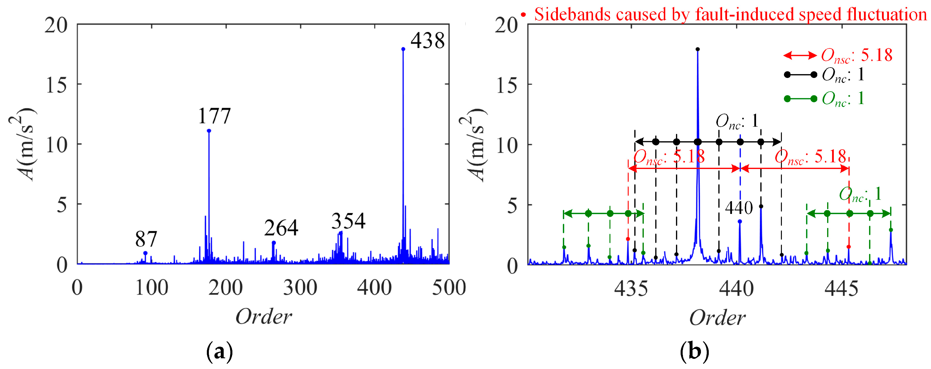
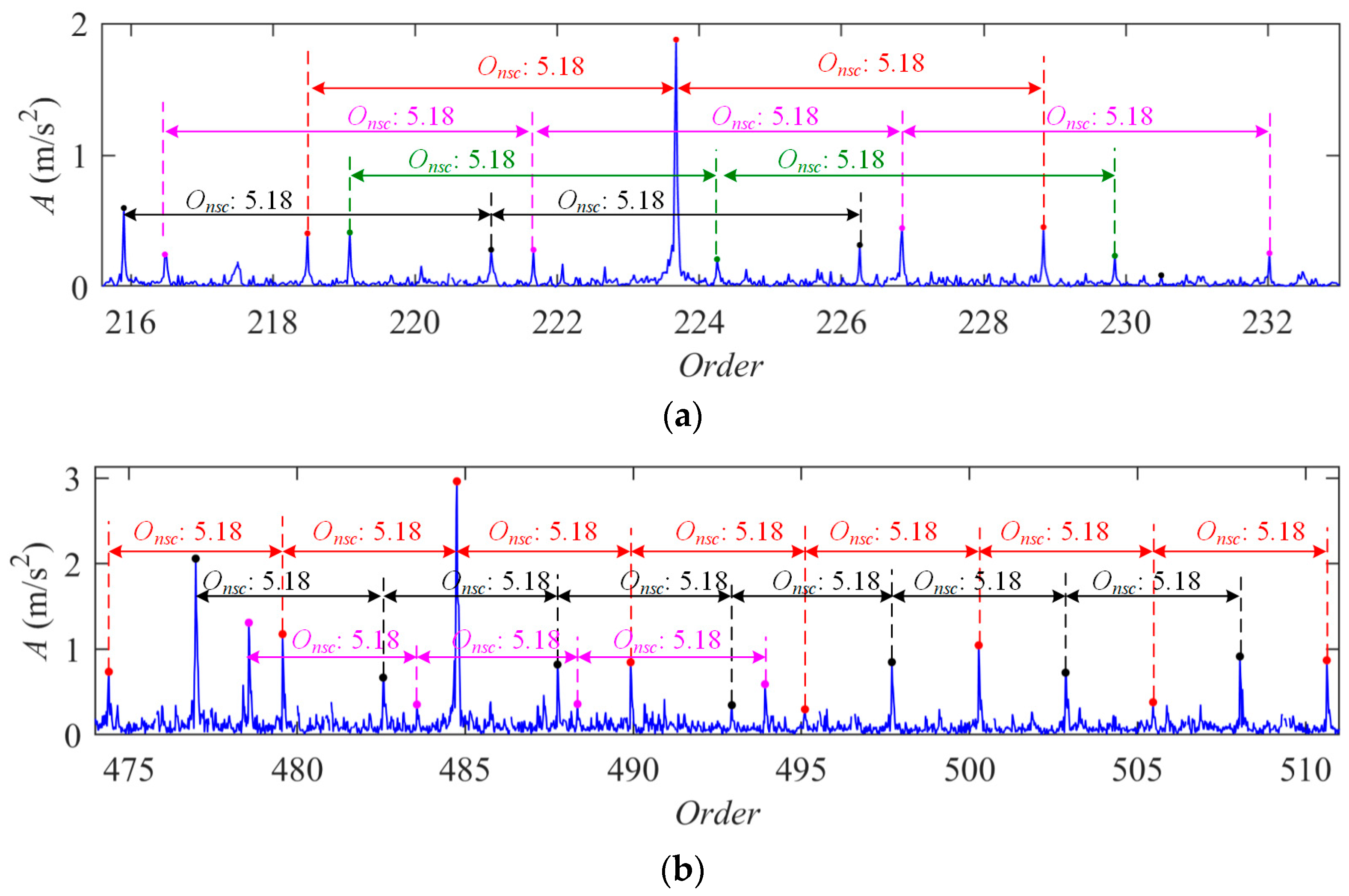
| Fault feature order of sun gear | 5.18 | 6 | ||||
| Transmission ratio | 6.18 | 7 | ||||
| Meshing order | 88 | 90 | ||||
Disclaimer/Publisher’s Note: The statements, opinions and data contained in all publications are solely those of the individual author(s) and contributor(s) and not of MDPI and/or the editor(s). MDPI and/or the editor(s) disclaim responsibility for any injury to people or property resulting from any ideas, methods, instructions or products referred to in the content. |
© 2025 by the authors. Licensee MDPI, Basel, Switzerland. This article is an open access article distributed under the terms and conditions of the Creative Commons Attribution (CC BY) license (https://creativecommons.org/licenses/by/4.0/).
Share and Cite
Yang, X.; He, G.; Du, C.; Xu, L.; Yu, J.; Zeng, H.; Li, Y. Superiority of Fault-Caused-Speed-Fluctuation-Based Dynamics Modeling: An Example on Planetary Gearbox with Cracked Sun Gear. Machines 2025, 13, 500. https://doi.org/10.3390/machines13060500
Yang X, He G, Du C, Xu L, Yu J, Zeng H, Li Y. Superiority of Fault-Caused-Speed-Fluctuation-Based Dynamics Modeling: An Example on Planetary Gearbox with Cracked Sun Gear. Machines. 2025; 13(6):500. https://doi.org/10.3390/machines13060500
Chicago/Turabian StyleYang, Xiaoqing, Guolin He, Canyi Du, Lei Xu, Junjie Yu, Haiyang Zeng, and Yanfeng Li. 2025. "Superiority of Fault-Caused-Speed-Fluctuation-Based Dynamics Modeling: An Example on Planetary Gearbox with Cracked Sun Gear" Machines 13, no. 6: 500. https://doi.org/10.3390/machines13060500
APA StyleYang, X., He, G., Du, C., Xu, L., Yu, J., Zeng, H., & Li, Y. (2025). Superiority of Fault-Caused-Speed-Fluctuation-Based Dynamics Modeling: An Example on Planetary Gearbox with Cracked Sun Gear. Machines, 13(6), 500. https://doi.org/10.3390/machines13060500