1. Introduction
Automation within medical procedures is continuously advancing, driven by the goal of increasing procedural precision, reducing inherent risks, and safeguarding healthcare professionals from exposure to potentially harmful conditions [
1]. Its rapid integration into surgical practices has become indispensable due to consistent, precise, and repeatable performance [
2,
3], while robotic assistance further mitigates physical strain on surgeons and radiation exposure risks in imaging-guided interventions [
4].
Surgical environments frequently involve complex medical apparatus that demand considerable expertise for intricate calibration and precise positioning [
5]. Even minor misalignments may compromise procedural efficiency and outcomes, emphasizing the value of seamless coordination between surgeons and device operators. Similar challenges have been reported in the design of flexible instruments for endoscopic procedures, where accurate 3D shape analysis is essential for safe and effective navigation [
6]. Fluoroscopy exemplifies such equipment, extensively used across minimally invasive and interventional radiological procedures [
7]. By employing X-rays for real-time imaging, fluoroscopy assists in navigating instruments within the patient’s body [
8] and is typically mounted on a mobile, highly maneuverable C-Arm to enhance coverage and procedural accuracy [
9]. However, it poses substantial risks from ionizing radiation exposure [
10], which can lead to skin injuries or long-term carcinogenic effects for patients [
11], while also threatening the long-term health of surgeons through cumulative exposure [
12,
13]. Moreover, operating the C-Arm’s complex kinematics manually is time-consuming, especially when re-establishing the optimal imaging perspective, which prolongs surgeries and increases radiation doses [
14,
15].
Although complete elimination of radiation in fluoroscopy-guided procedures is infeasible, automation has the potential to reduce radiation exposure; the magnitude will depend on workflow integration and system latency. The field of minimally invasive surgery, notably aortic catheter insertion procedures, has gained significant advantages from robotic solutions that permit remote catheter navigation, thereby lowering radiation exposure for the surgeon [
16]. However, most existing systems still rely on separate operators for each robotic device, presenting both safety and coordination challenges if one operator attempts to handle multiple devices simultaneously [
17].
Recent developments in endovascular robotics show that commercially deployed platforms—most notably Corindus’s
CorPath GRX and Hansen Medical’s
Magellan—already enable radiation-shielded, joystick-driven catheter navigation from a remote cockpit [
18,
19]. These systems still depend on a scrub-side assistant to swing the fluoroscopic C-arm, preventing true imaging–motion synchrony and limiting tele-presence. Emerging work on automatic C-arm repositioning—ranging from the self-driving
CIARTIC Move mobile arm to learning-based view-planning networks that infer target angles directly from 2-D images [
20]—begins to close this loop; however, current solutions either require pre-operative CT or markers or cannot track the continuously deforming shaft of a flexible catheter in real time. At the systems level, cooperative multi-robot architectures that couple imaging and manipulation remain largely confined to simulation benches or single-arm demos, with no bilateral control of both imaging and actuation reported in vivo [
21,
22]. This persistent gap motivates the cooperative bilateral framework proposed here.
During fluoroscopy-guided catheterisation the team remains exposed to ionising radiation because a scrub-side assistant must manually steer the C-arm and the surgeon must mentally coordinate a tendon-driven catheter robot with that moving imager. To eliminate this two-fold burden, we develop an advanced bilateral control scheme that streams real-time X-ray images into a controller driving both a 3-DoF robotic catheter and a 3-DoF C-arm so that the fluoroscope autonomously re-aligns with each catheter motion while concentrating the beam on the region of interest (quantitative dosimetry is reserved for future work). The framework combines (i) analytic kinematics that map joint angles to catheter centre-line shape, (ii) a calibrated projection model of the C-arm that generates synthetic radiographs of the catheter and surrounding vasculature, and (iii) image-processing pipelines that retrieve the catheter’s bending angle and orientation—vital inputs for the bilateral controller. As a forward-looking extension, we prototype a fully autonomous insertion routine that follows patient-specific centre-lines along predefined navigation paths, reducing reliance on operator skill and foreshadowing entirely hands-free workflows. The main contributions are threefold: (1) the first closed-loop, bidirectional control law synchronising catheter motion with autonomous C-arm repositioning; (2) a hybrid physics–projection simulator that blends finite-element catheter mechanics, calibrated X-ray rendering, and the above insertion routine for in silico experimentation; and (3) quantitative validation showing inverse-kinematic percentage errors for bending angles 20–90 (rising to at ) and an image-based angle-estimator RMSE over the same range, establishing a baseline for forthcoming hardware-in-the-loop trials.
The paper outline is as follows:
Section 2 details the kinematics, projection model, and image pipeline;
Section 3 derives the bilateral control algorithm;
Section 4 presents simulation validation, including the autonomous insertion study;
Section 5 discusses limitations, dosimetry plans, and translational pathways;
Section 6 concludes the study.
2. Methods
The Methods Section lays out this study’s theoretical foundations and core methodologies. It begins by outlining the kinematics of the C-Arm and flexible catheter, showing how forward and inverse kinematics can be derived for each device. It then covers the mathematical model for the fluoroscopic projection and details the image processing techniques for estimating catheter bending angles. These elements collectively form the framework that enables coordinated control of both the C-Arm and the catheter.
2.1. C-Arm Manipulation
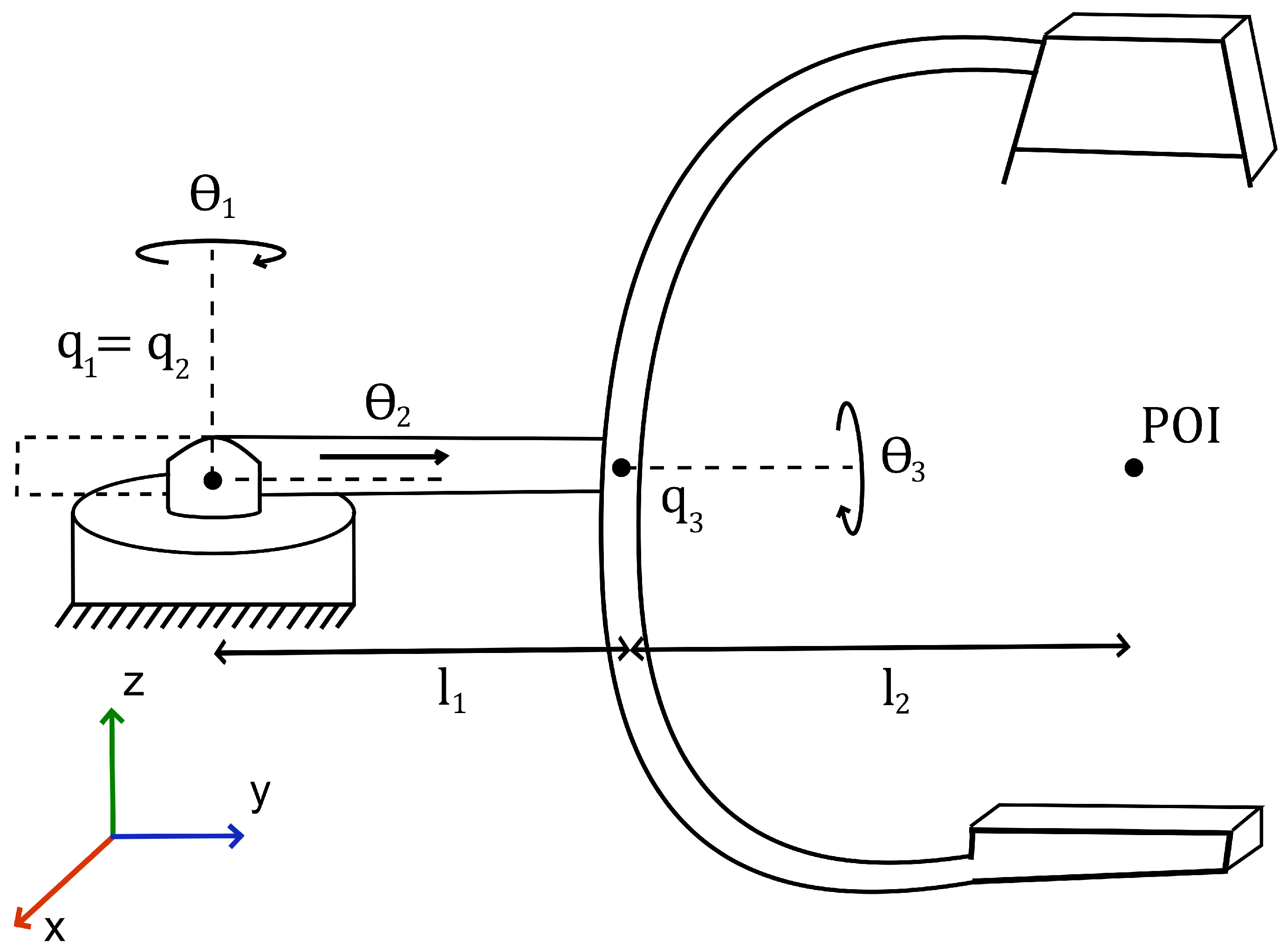
2.1.1. Forward Kinematics
We model the C-Arm part of the system as a 3-DOF robotic manipulator. A diagram of said manipulator is given in
Figure 1.
The application of screw theory allows for the full transformation, from the base to the end-effector of the manipulator, to be described by Equation (
1).
are the corresponding 4 × 4 screw-axis twists, and is the home homogeneous transform.
We can now evaluate Equation (
1) as
In Equation (
2),
and
are the rotation matrix and translation vector extracted from
, in which
and
. To simplify representation let us define
and
. We can then express
as
and
as
are the fixed link lengths;
and
are the current and home end-effector coordinates in the base
-plane. The full transformation from base to end-effector is now completely described by Equation (
2).
2.1.2. Inverse Kinematics
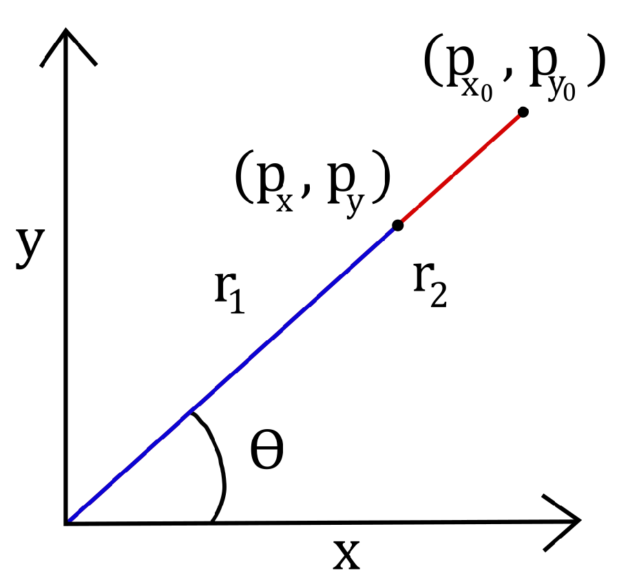
Inverse kinematics are derived using geometric analysis methods. The first joint of the C-Arm has rotational movement fixed in the x-y plane. The second joint of the C-Arm actuates a prismatic translation within the x-y plane. An abstraction is given in
Figure 2.
Using polar coordinates, the angle of the first joint is straightforward to determine.
For some angle , the difference in the magnitude of the end-effector in the current and zero configuration gives the joint angle .
The joint angle
is simply the difference in radii.
Here, and ; hence, .
2.2. Roboticising a Flexible Catheter
2.2.1. Forward Kinematics
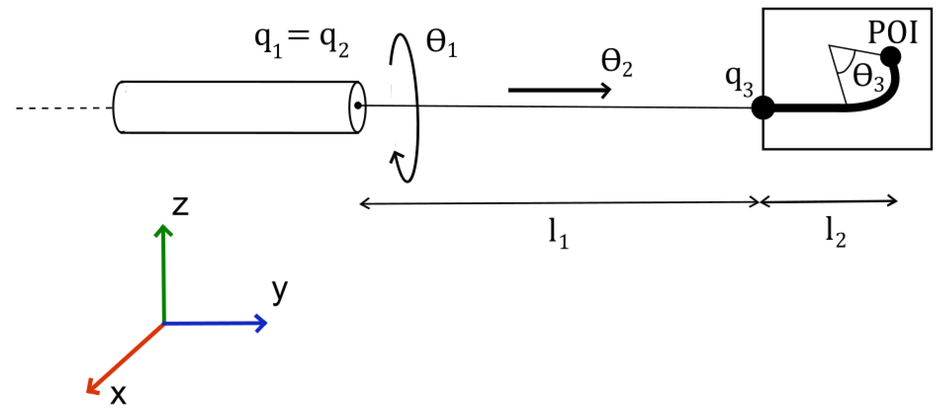
The forward kinematics of the flexible catheter are derived differently from that of the C-Arms. Two joints shall have their homogeneous transformations determined via screw theory, whilst the final joint shall be determined using geometric analysis.
A diagram defining the relevant parameters of the manipulator is given in
Figure 3.
The complete transformation is now described by Equation (
7).
The transformation matrix represents the rigid-body transform that maps frame 2 to frame 3, corresponding to the bending segment.
Equation (
7) is evaluated as
We use the same representations as for the previous transformation matrix.
can then be expressed as
and
as
The tip position combines the straight-segment length with the arc-length contribution .
Equation (
8) now fully describes the transformation from base to end-effector.
2.2.2. Inverse Kinematics
The first joint is revolved about the y-axis. This will affect the rotation of the bending plane of the catheter. The second joint is prismatic along the y-axis. The third, the bending joint, has movement within the bending plane.
The prismatic joint is straightforward. An abstraction is shown in
Figure 2 with
.
Turning to joint 3, the geometric analysis yields functions that cannot be solved algebraically. Instead, the following transcendental function can be solved to determine the required joint angle.
To determine the solution to this equation, we require
such that
The value or values (as there can be infinitely many solutions) that satisfy the above equation will also be the global minimiser or minimisers of the optimisation problem.
The transcendental equation for is solved numerically (Newton–Raphson) to obtain the bending joint angle. For the catheter, this is assumed to be known. The C-Arm requires extra modelling to devise a method that allows for the determination of the required for some position.
2.3. Fluoroscope Projection and Image Processing
Modelling the Projection
Each point on the catheter within the projection window is defined as the set , where is the index of each point within the set. The projection is then the map .
The transform
can be expressed as the composition of the maps of the separate stages of the projection.
where
l,
r,
t,
b denote the left, right, top, and bottom image-plane borders and
n is the near-plane distance, in which
and
In applying the transformation to every element in C, we acquire the set , where is the index of each point within the set.
2.4. Idealised Projection and Baseline Image Pipeline
The algorithm in this section is solely intended to validate the control loop and therefore does not yet account for scatter, anatomical clutter, or quantum noise; these factors will be addressed in subsequent physical experiments.
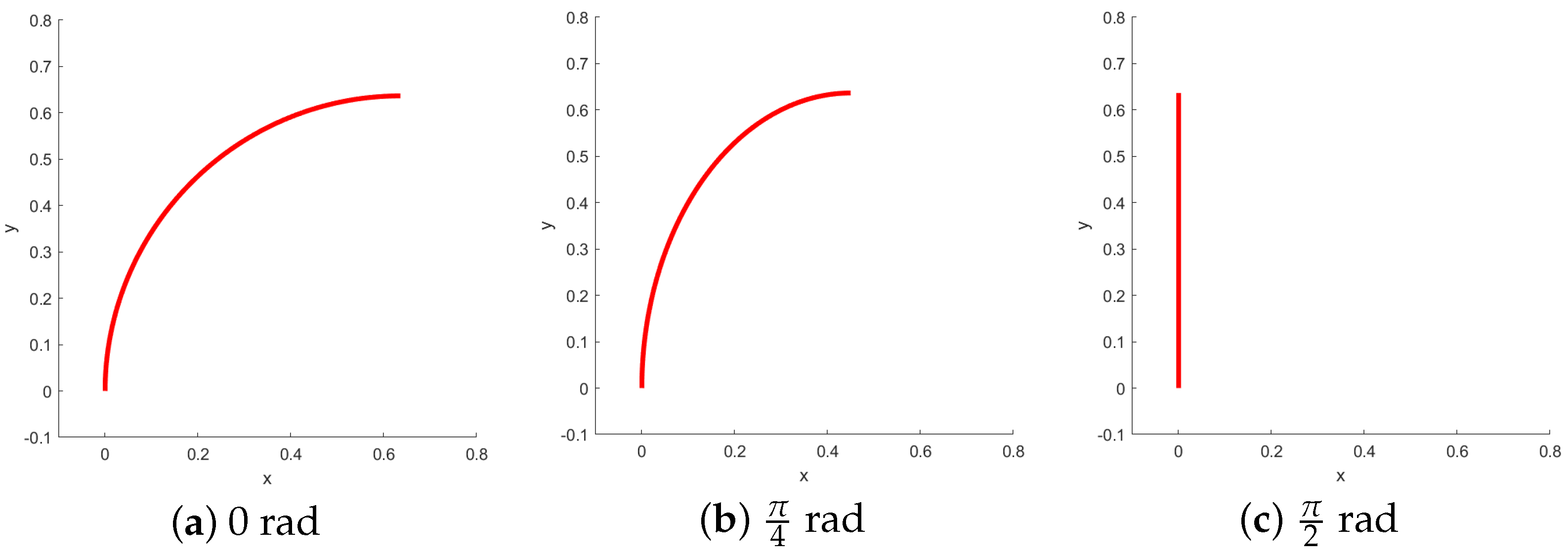
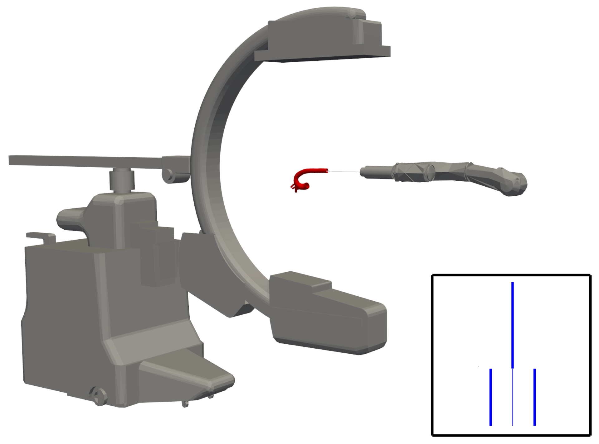
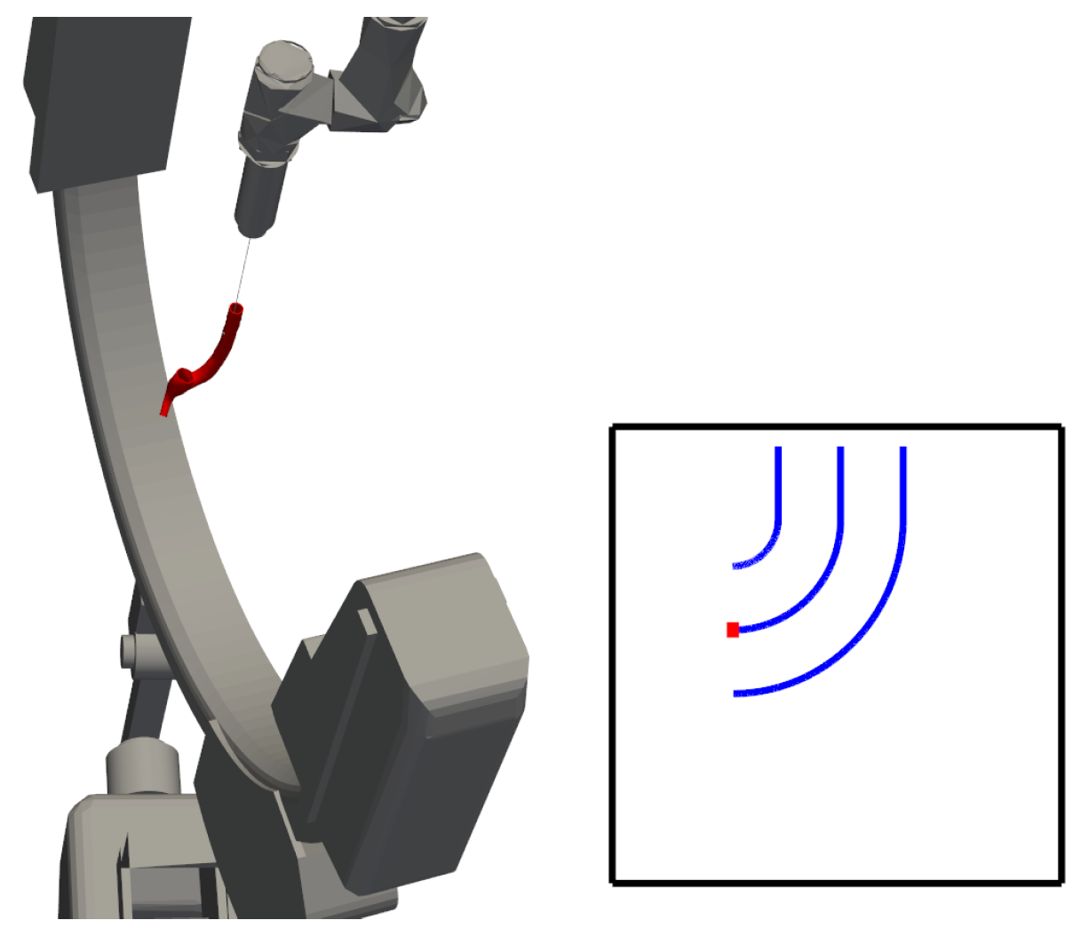
In this context, it is crucial to determine the rotation of the bending plane, as it directly affects the perceived bending angle from a fixed viewpoint, as illustrated in
Figure 4.
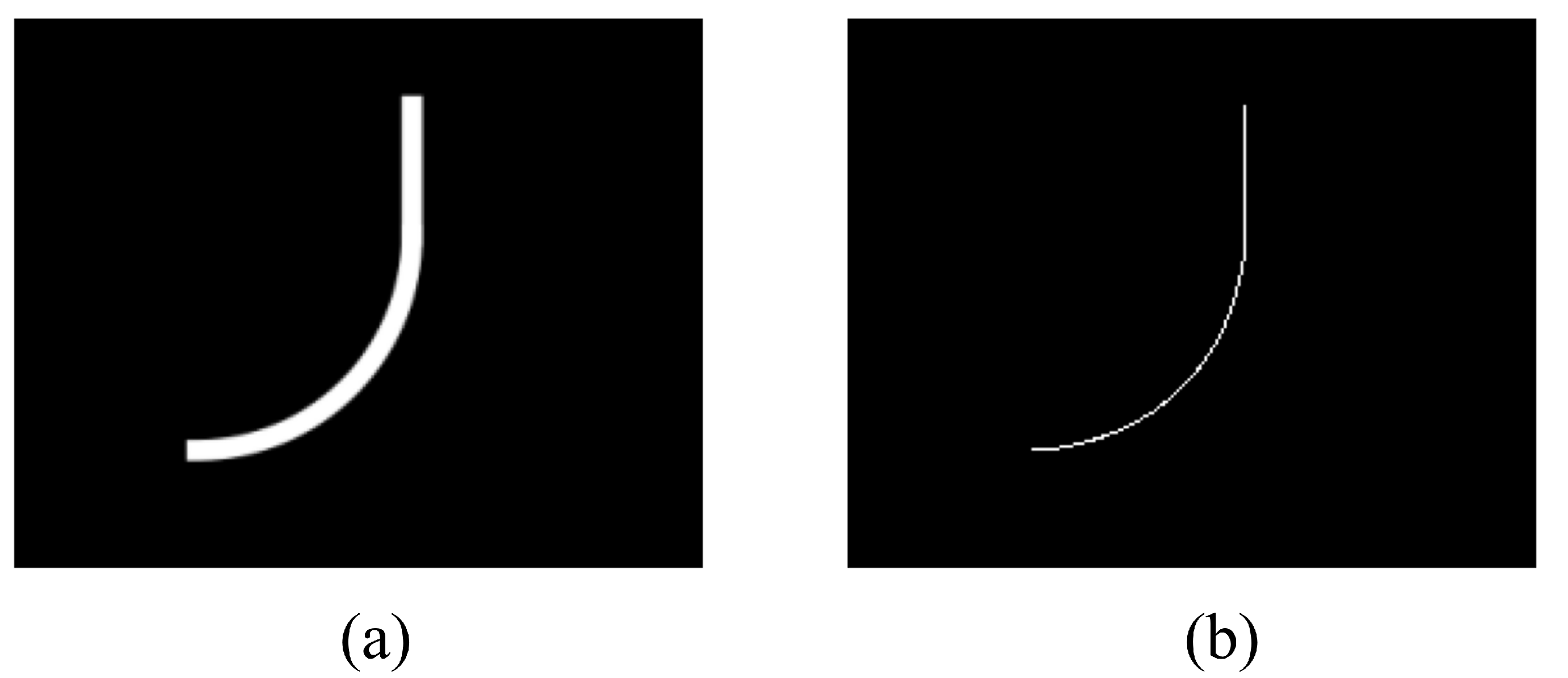
Angle estimation allows one to detect this change in orientation. The projection model gives us an image of the form shown in
Figure 5. The pixel intensities are inverted to mimic the white-background, dark-catheter appearance of clinical fluoroscopy.
It should be noted that, for this research, the artificial image is ideal. The effects of noise, blurring, and additional objects within the image are ignored.
To discern whether a pixel belongs to the background or the catheter, a process known as segmentation must be applied. Regions are formed in the image, with pixels belonging to objects or a specific part of an object within that image.
If we let
R represent the entire spatial region occupied by the image,
in which
represents the pixels belonging to the catheter and
those belonging to the background.
As the ideal image is simple, thresholding is adequate to segment the image. A histogram of the image’s pixel intensities is created. Thresholds are then chosen to segment the image into the desired regions of interest. Let
represent the pixel intensity threshold and
the pixel intensity within the image. We can then define
as the binary value of that pixel after the threshold has been applied.
We can reduce the binary objects to a 1-pixel-wide representation to simplify feature extraction. This is called skeletonisation. It entails making successive passes of the image to identify pixel borders, which are removed on the condition that the connectivity of the corresponding object is not broken. The image in
Figure 5 results from all this combined processing.
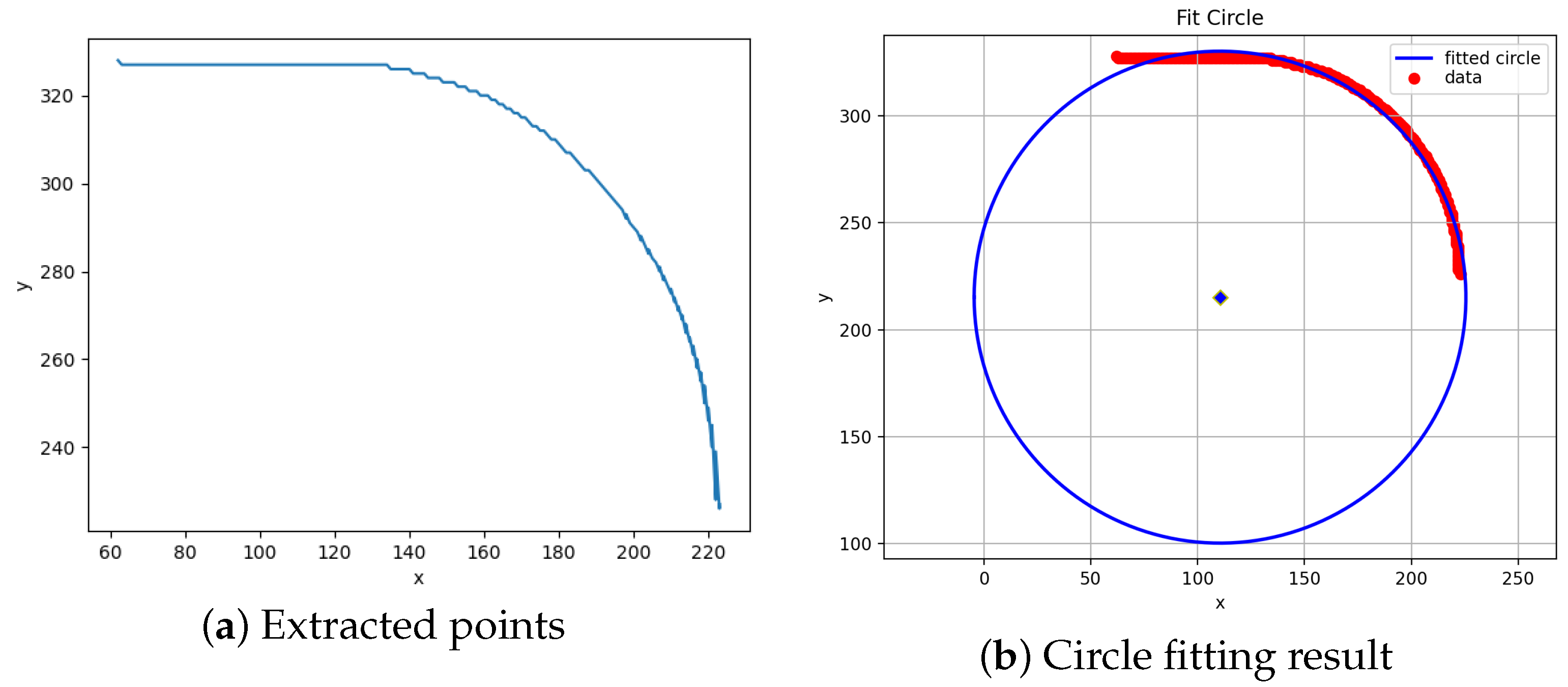
Extracting the location of each pixel with the binary value corresponding to region
yields the set
.
Figure 6 results from plotting each element of the set.
The bending part of the catheter is well-modelled as the segment of a circle. One can obtain the bending angle using the equations of an arc length, namely, . l is a known quantity; hence, a method of obtaining r is required.
Acquiring the circle corresponding to the segment acting as the flexible portion of the catheter can be performed using a fitting algorithm. This comprises solving a minimisation problem to obtain the best estimate of a circle that fits all the points in . An estimate of the angle follows from this.
For the vectors belonging to the set
, we define the equation of an ideal circle.
where
is the index of a vector belonging to
. Rewriting the expression,
in which
For every vector in
, the whole system can be written in matrix form. Let
n be the number of vectors belonging to the set
. Then,
where
,
, and
. The optimal solution to this inconsistent system of equations is given by
where
. Rearranging the original expression for
a,
b, and
c,
We obtain the parameters of the best-fitting circle for .
The results of applying the fitting algorithm to the points displayed in
Figure 6a are seen in
Figure 6b.
3. C-Arm Control Strategy Design
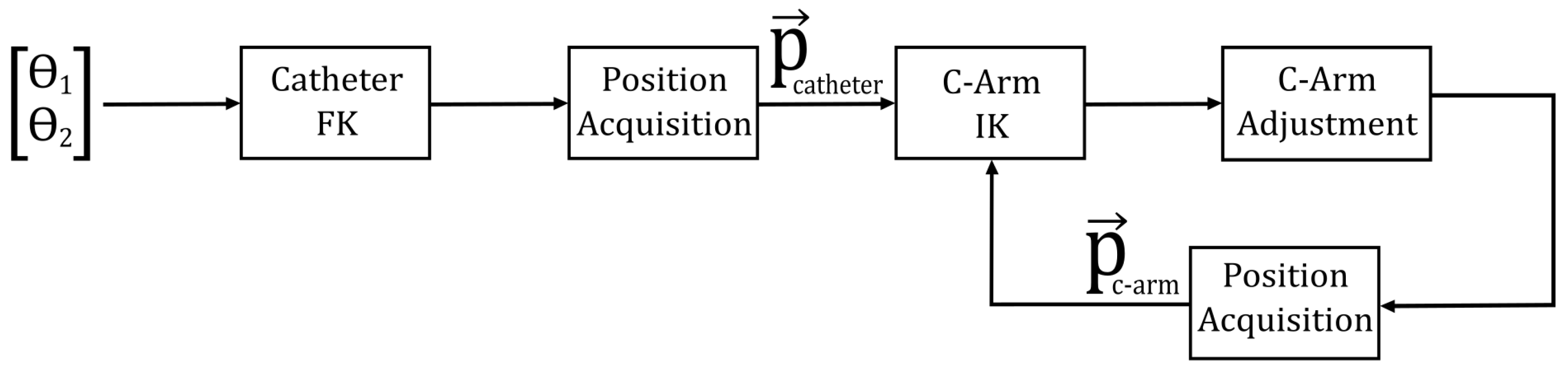
Each control cycle proceeds as follows: the fluoroscope acquires an image; the bending angle
is extracted; the resulting angle error is mapped, via the C-arm Jacobian, to a correction
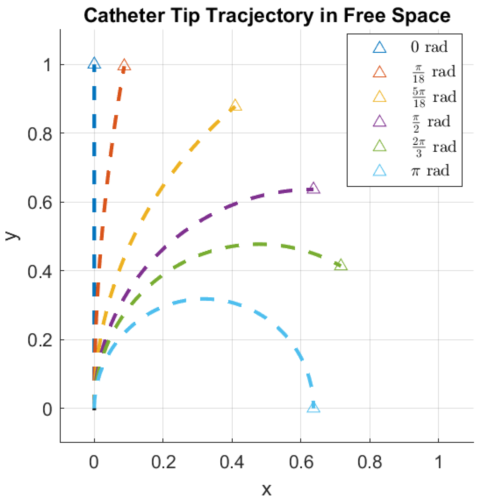
of joint 3; and the updated pose is applied to the next frame. It is assumed that the system dynamics are sufficiently regulated, with “control” herein referring specifically to the high-level management of the manipulator kinematics. Within this framework, the maintenance of an optimal camera position relative to the catheter tip, within its bending plane, is achieved solely through the inverse kinematics of the C-arm. The catheter tip position—obtained by methods presumed to be available—is directly integrated as an input into the kinematic models, thereby enabling the dynamic adjustment of the C-arm manipulator configuration in response to the catheter’s insertion and bending movements.
Figure 7 presents a schematic representation of this control strategy.
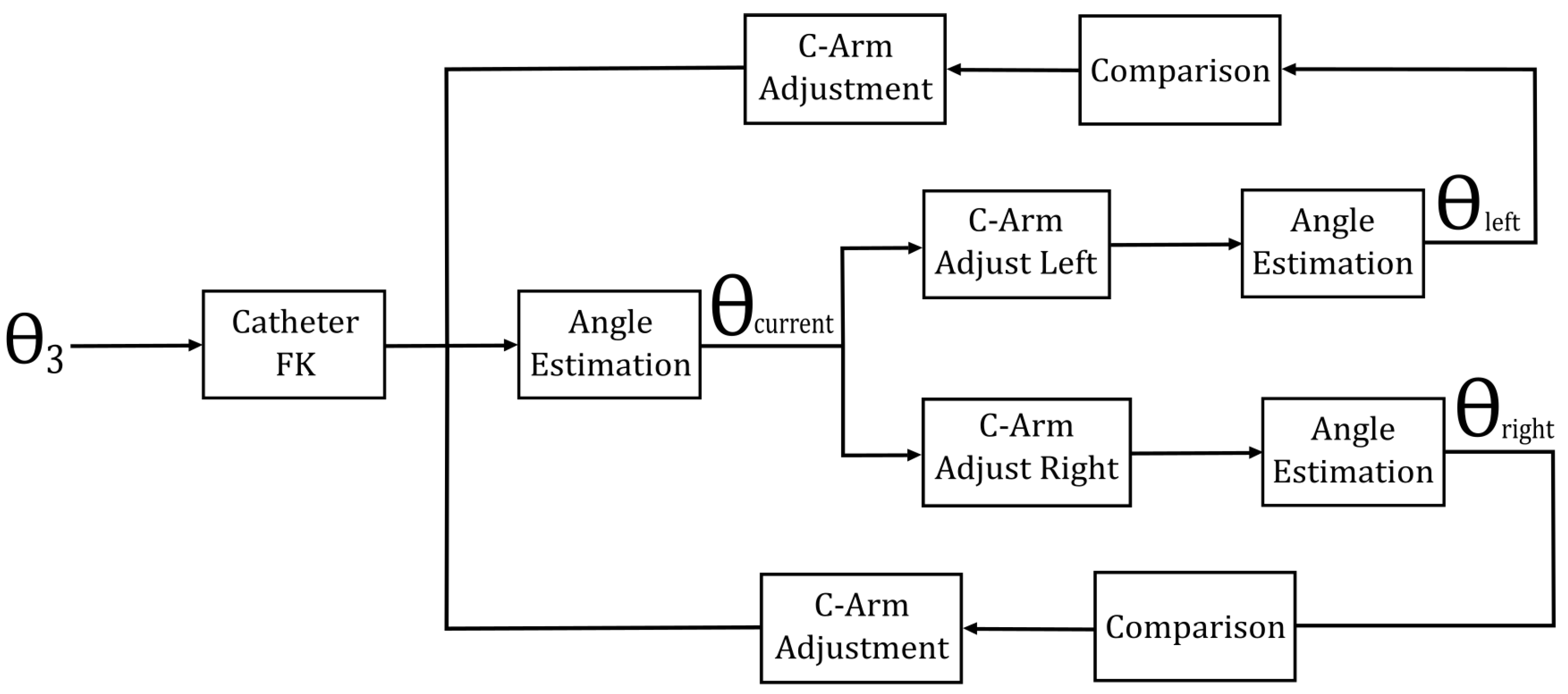
It is important to note that the rotation of the catheter relative to the fluoroscope’s perspective introduces ambiguity in angle estimation. Specifically, the “actual” angle (or best estimate) is defined as the maximum angle perceived by the estimator. As the catheter rotates, an illusion of an increasing bending radius arises, which in turn leads to a reduction in the estimated bending angle.
The rotation of the catheter’s third joint is continuous, closed, and bounded within the interval
. Consequently, the extreme value theorem can be applied. Let
f be a function representing the estimated angle for a given orientation of the catheter. Since
f is continuous, closed, and bounded on the interval
, it follows that
where
.
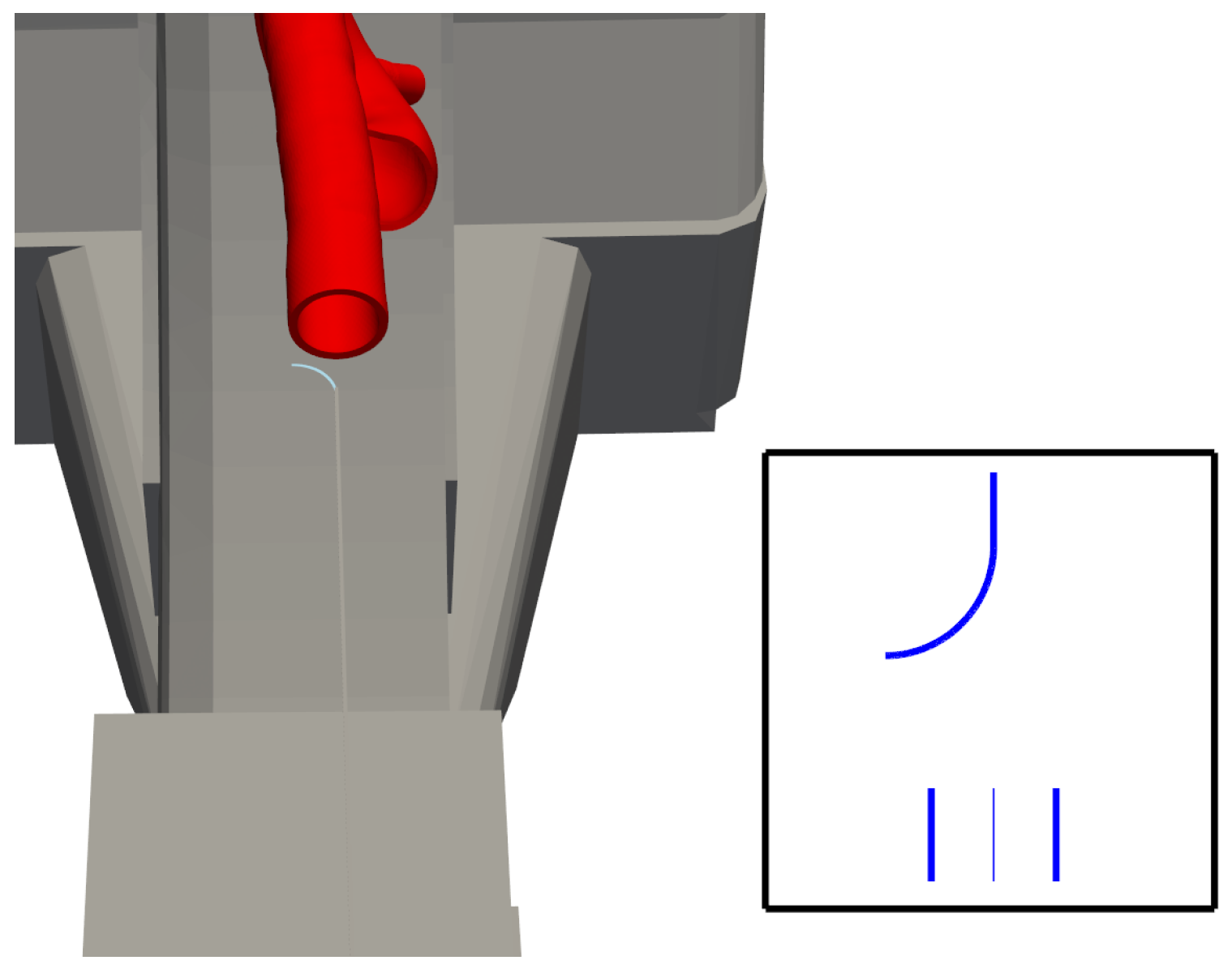
This theoretical foundation facilitates the development of a search algorithm that enables the C-arm to ascertain its optimal position. Initially, the angle estimator defines the current perceived angle. Subsequently, the C-arm’s third joint is rotated both to the left and right of the current angle, with the perceived angles at these positions being compared to the current value. Upon detecting an increase in the perceived angle in one direction, the C-arm continues rotating and re-estimating the angle until the estimation begins to decline. The maximum angle perceived prior to the decline is then taken as the optimal (maximum perceived) angle, and the C-arm defines its operational position accordingly.
Figure 8 illustrates the control method for optimal perspective tracking.
Each control cycle proceeds as follows: the fluoroscope acquires an image; the bending angle is extracted; the resulting angle error is mapped, via the C-arm Jacobian, to a correction of joint 3; and the updated pose is applied for the next frame.
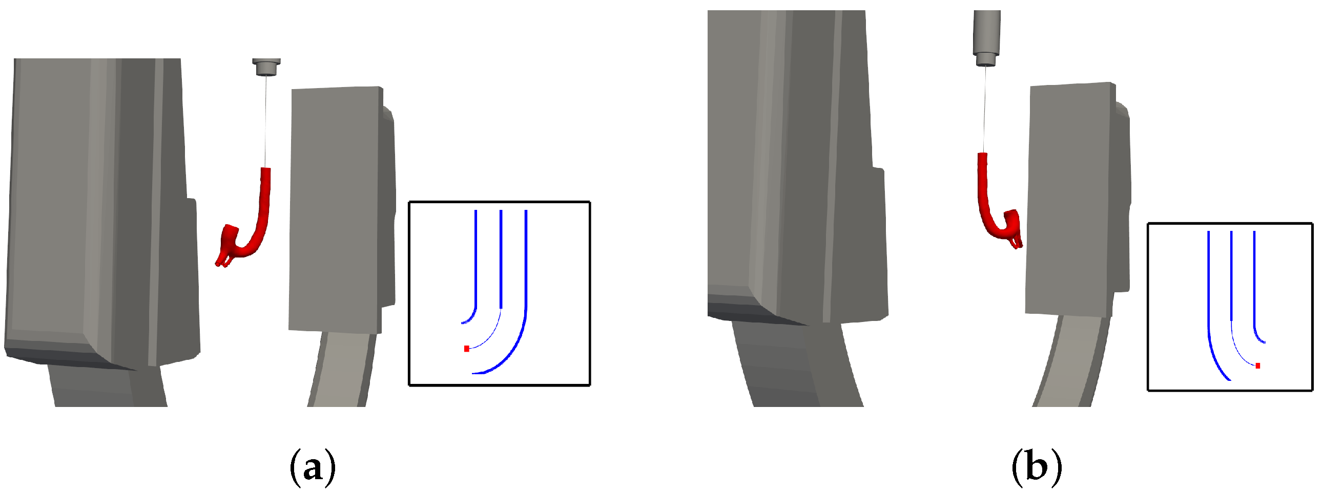
Moreover, full system automation is achieved by incorporating an additional preliminary step into the block diagram shown in
Figure 7. By employing the inverse kinematics of the catheter manipulator, the system is enabled to follow a preplanned trajectory with high precision, thereby further enhancing operational efficiency and control accuracy.
5. Discussion
This section describes the simulation environment created to test and validate the feasibility of the proposed dual-manipulator control scheme. It demonstrates how the forward and inverse kinematics, along with the projection model and image processing pipeline, function together under realistic conditions. Quantitative evaluations of accuracy—such as the catheter’s bending angle estimation and the inverse kinematics solutions—confirm the viability of the approach and reveal areas for refinement.
5.1. Summary and Reflection
This research aimed to demonstrate a method of coordinating multiple medical devices in a catheter insertion procedure by utilizing two robotic manipulators. Through basic kinematics, one manipulator achieved rudimentary C-arm tracking of the catheter within its bending plane. Meanwhile, a mathematical formulation of the fluoroscope’s projection enabled the creation of artificial images, from which the bending angle was estimated using image processing. A search algorithm then identified the optimal C-arm position relative to the catheter, defined here as “the position at which the ‘actual’ angle (or best estimate) is perceived angle by the estimator ”, corresponding to the maximum estimated angle. Additionally, a path-tracking algorithm was employed to automate the insertion procedure fully. A simulation test bench verified the feasibility of these concepts, examining both angle-estimation accuracy and inverse kinematics performance.
Reflecting on the necessity of this approach, one must acknowledge potential drawbacks such as longer operating times and higher costs. However, such a system may help limit surgeons’ radiation exposure. Methods presented by De Silva et al. [
23] propose virtual fluoroscopy to pre-determine positioning, ultimately reducing procedure duration and radiation levels. The bilateral controller described here could potentially reduce or even obviate the need for direct C-arm operation. Concurrently, Kausch et al. [
20] implement a computer algorithm to automate C-arm positioning, although it relies on a “pre-scan” of the patient and is therefore less suited to continuously changing scenarios. Considering existing technologies presented by Matthäus et al. [
24] and Namrata et al. [
25], it becomes clear that more complex anatomical structures may challenge oversimplified models. The present work employs relatively straightforward manipulator assumptions, yet the core bilateral control scheme remains applicable even under greater realism. What may shift is the path-tracking aspect, given that real aortas typically deviate from the ideal shapes assumed in the simulator. Further advanced image processing methods, like those presented by Alam [
26], for extracting the true centre-line of a real aorta would produce a more robust system.
5.2. The Development of a Realistic Application
Building on the above reflections, the following points outline key requirements for developing a more realistic application of the proposed system:
Increased complexity in the manipulator model.
Introduction of noise and blurring effects to yield less idealised images.
More realistic modelling of the aorta.
Additional image processing techniques.
In practice, the manipulators will likely possess more degrees of freedom, and the flexible joint may exhibit hysteresis that demands dedicated modelling. Further image processing would also be necessary to determine the catheter’s position in the global frame, differentiate between straight and bending regions, and locate the aorta’s central lumen. Moreover, imposing boundaries on the C-arm’s permissible motion could clarify how the controller behaves in confined spaces.
In addition, future work will explore the integration of machine learning and deep learning techniques with biosignals [
27,
28,
29], such as the muscular activity of clinicians, to enable more adaptive and intelligent control strategies, thereby further enhancing the completeness and usability of the system.
5.3. Optimisation Potential and Limitations of Proposed System
5.3.1. Optimisation Potential
No explicit attention has yet been paid to optimizing the control approach. Potential avenues for improvement include
Adjusting the C-arm’s step size;
Minimizing the steps required for optimal positioning;
Reducing control effort while maintaining performance;
Constraining the catheter’s maximum deviation from a planned path during automatic insertion.
Improving efficiency in these areas may reduce overall control demands and boost precision. Consequently, the risk of path deviation could diminish, although this would likely depend on refined path-planning algorithms as well.
5.3.2. System Limitations
For small bending angles, automated catheter insertion currently suffers from significant inaccuracy since the inverse kinematics method may yield large errors below around . Given that the catheter is narrower than the aorta, minor deviations at low angles are unlikely to cause wall collisions. Nonetheless, introducing an improved initial-guess strategy could better guide the root-finding algorithm.
Furthermore, in clinical endovascular procedures, vessels can sometimes feature curvatures greater than 90°, posing additional challenges for catheter navigation. Our current study and simulation models have not yet been validated for such extreme bends. Future work will therefore incorporate a more robust kinematic model and imaging strategy to address higher bending angles, better reflecting real-world vascular complexities.
Lastly, the impact of latency in hardware communication has yet to be modeled. This gap invites questions such as how automatic and manual insertion times compare and how rapidly the C-arm can reposition itself when the catheter’s shape changes. Addressing these issues will be central to understanding the bilateral control framework’s performance in practical surgical scenarios and may encourage broader adoption of the proposed methods.
6. Conclusions
This paper presented a potential approach for coordinating multiple medical devices via a bilateral control scheme, leveraging a flexible catheter’s position and bending angle to automate the control of a C-arm fluoroscope. Such coordination may not only streamline the catheter insertion process but also help mitigate radiation risks for both surgeon and patient. By incorporating path tracking for catheter navigation, this control scheme aims to enable full procedural automation, although further testing in realistic scenarios is still recommended.
Analytical methods were used to derive inverse and forward kinematics for both systems, and the resulting transformation matrices were detailed. Forward kinematics relied on a series of linear transformations from base to end-effector, while inverse kinematics combined geometric analysis with function minimisation. Although the kinematic models proved sufficient for manual catheter control, inaccuracies arose at small bending angles during automatic insertion, leading to slight deviations from the intended path.
Additionally, the fluoroscope projection was modeled to generate artificial images, from which bending angles were inferred through image processing. Recognizing that perceived bending angles vary with catheter orientation, a search-based approach was implemented to optimise the fluoroscope’s vantage point. This estimator showed promising accuracy, thus supporting a robust C-arm positioning strategy.
A test bench simulator was developed to validate the system models and to illustrate how the bilateral controller might operate in practice. These outcomes suggest that the proposed concept is technically feasible, offering a new perspective on automating catheter insertion procedures. Nonetheless, further refinements—particularly for real-world surgical environments—would be instrumental in advancing this framework from simulation to clinical application.


