Abstract
Three-phase induction motors are widely adopted in industrial systems due to their robustness, ease of maintenance, and simple operation. However, they are prone to various types of faults, notably stator winding faults. Previous research indicates that 20–40% of three-phase induction motor failures are stator-related, with inter-turn short circuits as a leading cause. These faults can pose significant risks to both the motor and connected equipment. Therefore, the early detection of inter-turn short circuit (ITSC) faults is essential to prevent system breakdowns and improve the safety and reliability of industrial operations. This paper presents a comparative investigation of two distinct diagnostic methodologies for the detection of ITSC faults in induction motors. The first methodology is based on a Motor Current Signature Analysis (MCSA) utilizing the short-time Fourier transform (STFT) for the real-time monitoring of fault-related harmonics. The second methodology is centered around the monitoring of the zero-sequence voltage (ZSV). The findings from several experimental tests performed on a 1.1 kW three-phase induction motor across a range of operating conditions highlight the superior performance of the ZSV method with respect to the MCSA-based STFT method in terms of reliability, rapidity, and precision for the diagnosis of ITSC faults.
1. Introduction
Three-phase induction motors (IMs) are among the most commonly used rotating electrical machines in industry, owing to their durability, simplicity of construction, and high reliability [1]. They are essential components in sectors such as manufacturing, processing, power systems, and transportation. However, these motors frequently operate under demanding mechanical and electrical conditions, making them susceptible to faults, particularly in the stator and rotor [2]. Research indicates that stator winding faults are the most common cause of electrical machine failures, accounting for 20% to 40% of all faults in three-phase induction machines [3] and reaching 66% in high-voltage motors [4].
Inter-turn short-circuit (ITSC) faults present a significant hazard due to their potential for catastrophic outcomes [5]. These faults initiate with the failure of insulation between stator turns, typically resulting from the gradual degradation under various operational stresses (including thermal, electrical, mechanical, and environmental) [6]. The immediate effect is excessive current circulating within the short-circuited windings, leading to elevated temperatures in the affected turns. This temperature increase further accelerates insulation deterioration, reducing its resistance and intensifying the fault current, thereby creating a localized hot spot [7]. Consequently, the insulation strength of adjacent turns is compromised, leading to an expansion of the shorted region. Even if the fault affects only a few turns, it can quickly escalate and cause severe fault types, such as phase-to-ground or phase-to-phase faults [8].
Health condition monitoring and fault detection systems for three-phase induction motors are important because of these motors’ vital role and widespread use in a variety of industries [9]. Their role is to transform maintenance from reactive or purely time-based approaches into a proactive, data-driven strategy. Indeed, modern industrial systems are facing increasing pressure to enhance both safety and reliability, driven by expanding electrification and the imperative to extend equipment lifespans [10]. Consequently, early fault detection achieved through these systems is paramount for enabling proactive maintenance strategies that minimize financial expenditures and operational downtime [11]. Early detection not only reduces repair costs by addressing issues before they escalate but also mitigates production losses and overall disruptions [12]. This growing need has spurred a concerted effort toward developing new diagnostic techniques specifically designed to detect faults in their initial stages, further highlighting the value of the proactive approach, which leads directly to increased reliability, reduced operational costs, enhanced safety, an ensured continuous operation, and an extended equipment life across industries [13].
The development of proficient diagnostic frameworks for electrical machines necessitates a comprehensive understanding of fault mechanisms, their impact on operational characteristics, and their manifestation in quantifiable signals [14]. A multitude of fault detection methodologies have been proposed in the literature, subject to categorization based on diverse criteria. Prevalent classifications differentiate between invasive and noninvasive techniques, while others divide them into model-based [15] and signature-based [16] approaches. Invasive methodologies mandate the integration of supplementary sensors physically interfaced with the motor for acquiring required signals, typically encompassing acoustic noise [17], structural vibrations [18], and thermal measurements [19]. Conversely, noninvasive techniques present compelling advantages, including a cost reduction via the avoidance of sensor hardware, potentially enhanced precision in identifying incipient faults, and increased system dependability [20].
Notwithstanding these advancements, an ongoing demand persists for diagnostic algorithms exhibiting superior robustness, computational efficiency, and diagnostic accuracy [21]. Although the stator fault may also precipitate changes across a wide array of variables—including the rotational speed, temperature, back electromotive force (EMF), magnetic flux distribution, and potentially internal control system parameters—the stator phase current and voltage are conventionally employed as principal indicators for stator winding anomalies [22]. This complex interplay highlights the imperative for adopting integrated diagnostic strategies that leverage a diverse set of parameters to ensure an efficacious early fault detection and precise characterization.
In modern times, many three-phase induction motors are powered by variable frequency drives [23], which presents a particular problem. These drives are known to generate noise in measured quantities. VSI control can be achieved through either open-loop or closed-loop methods. Open-loop control, despite offering a lower performance than closed-loop alternatives, is frequently employed in steady-state industrial applications due to its low cost and simplicity [24]. However, a significant consequence of this lower performance is the harmonic distortion inherent in the motor current, leading to increased total harmonic distortion. This presents a serious challenge for diagnostics, as the harmonic content can interfere with existing fault detection methods, potentially compromising the reliability and conclusiveness of the results [25].
For the identification of stator winding fault symptoms in three-phase induction motors, a common technique involves the analysis of the stator voltage and current signals. Although the fast Fourier transform (FFT) is a widely adopted method for spectral analysis [26], its efficacy is limited by the requirement for stationary signals. Therefore, when dealing with the non-stationary characteristics of signals acquired from speed-controlled drives or the faulty state, alternative techniques are commonly employed for the stator current analysis. These techniques include the Hilbert–Huang transform (HHT) [27], short-time Fourier transform (STFT) [28], discrete wavelet transform (DWT) [29], higher-order spectral analysis [30], and Variational Mode Decomposition (VMD) [31].
Processing phase current and voltage signals using the methods mentioned enables the extraction of symptoms characteristic of stator winding faults in induction motors [32]. These symptoms can be used directly for diagnostics or as a basis for developing fault indicators and classifiers. However, a key challenge in creating effective motor fault indicators and classifiers lies in selecting an appropriate signal processing method that maximizes symptom extraction, thereby achieving the highest possible fault detection and classification efficiency.
This article aims to compare the effectiveness of two distinct methods for the online detection of ITSC faults through experimental validation. The first methodology, based on the MCSA, uses the short-time Fourier transform (STFT) to track the amplitude of specific harmonics generated by the occurrence of ITSC faults. The second methodology is based on monitoring the magnitude of the zero-sequence voltage (ZSV), which is derived through the application of the Fortescue transform to the fundamental harmonic components of the three-phase voltages and is also obtained through the STFT analysis.
2. Short-Time Fourier Transform Method
The fast Fourier transform (FFT), while offering a high frequency resolution, lacks the temporal resolution to pinpoint the precise timing of specific frequency events. This limitation is particularly critical when analyzing non-stationary signals [33], such as those from faulty motors, where the frequency content changes dynamically over time. An accurate fault diagnosis demands not only frequency information but also precise timing data to pinpoint the fault’s onset and progression. Time-frequency analysis techniques are therefore essential for an effective motor fault diagnosis. The STFT addresses this limitation by employing a sliding window function to generate a time-frequency representation of the signal [34]. This representation reveals both the temporal location and the frequency characteristics of transient events, providing critical information for an accurate fault detection and localization. Furthermore, the STFT allows for the tracking of specific frequency components within the signal [35], monitoring their amplitude and frequency over time. This capability is crucial for identifying characteristic frequencies associated with specific faults. This enhanced temporal and spectral resolution [14], obtained through the time-frequency analysis of the STFT, significantly improves the accuracy and reliability of the fault diagnosis. The calculation of the STFT is detailed in Equation (1).
is the input discrete-time signal.
represents the window function.
The indices m and ω correspond to the time and frequency indices.
3. The Spectral Analysis of the Stator Current
The MCSA is a popular noninvasive method for online fault detection in induction motors [36], offering several key advantages. It requires only the readily available stator current signal, eliminating the need for complex motor parameter estimations. The analysis of this signal reveals characteristic frequency components associated with various faults.
The foundation of the MCSA lies in the principle that each specific fault within an induction motor generates a unique and identifiable pattern of frequency components in the motor’s current spectrum [37]. This unique spectral signature acts as a “fingerprint” for that particular fault. Therefore, the diagnostic process using the MCSA involves analyzing the motor’s current frequency spectrum to identify the presence and relative amplitudes of these characteristic frequencies. The detection of these unique spectral signatures and their corresponding amplitudes allows for both the identification of the specific fault and, in some cases, its location within the motor. This approach to the fault diagnosis leverages the inherent relationship between the physical characteristics of a fault and its manifestation as specific frequency components in the motor’s electrical signature.
Some studies [38,39,40] state that the ITSC fault generates stator current harmonics at frequencies defined by
where fs is the supply voltage frequency; p represents the number of pole pairs; s is the slip, n; and ν and K are integers: n = 1, 2, 3 …, ν = 1, 2, 3 …, and K = 1, 3, 5 …
It is worth mentioning that the amplitudes of these stator current harmonics are tracked by the STFT technique, which allows for the continuous estimation of their magnitudes from the signal’s spectrum. This continuous amplitude data enables online or real-time monitoring for induction motor’s fault detection.
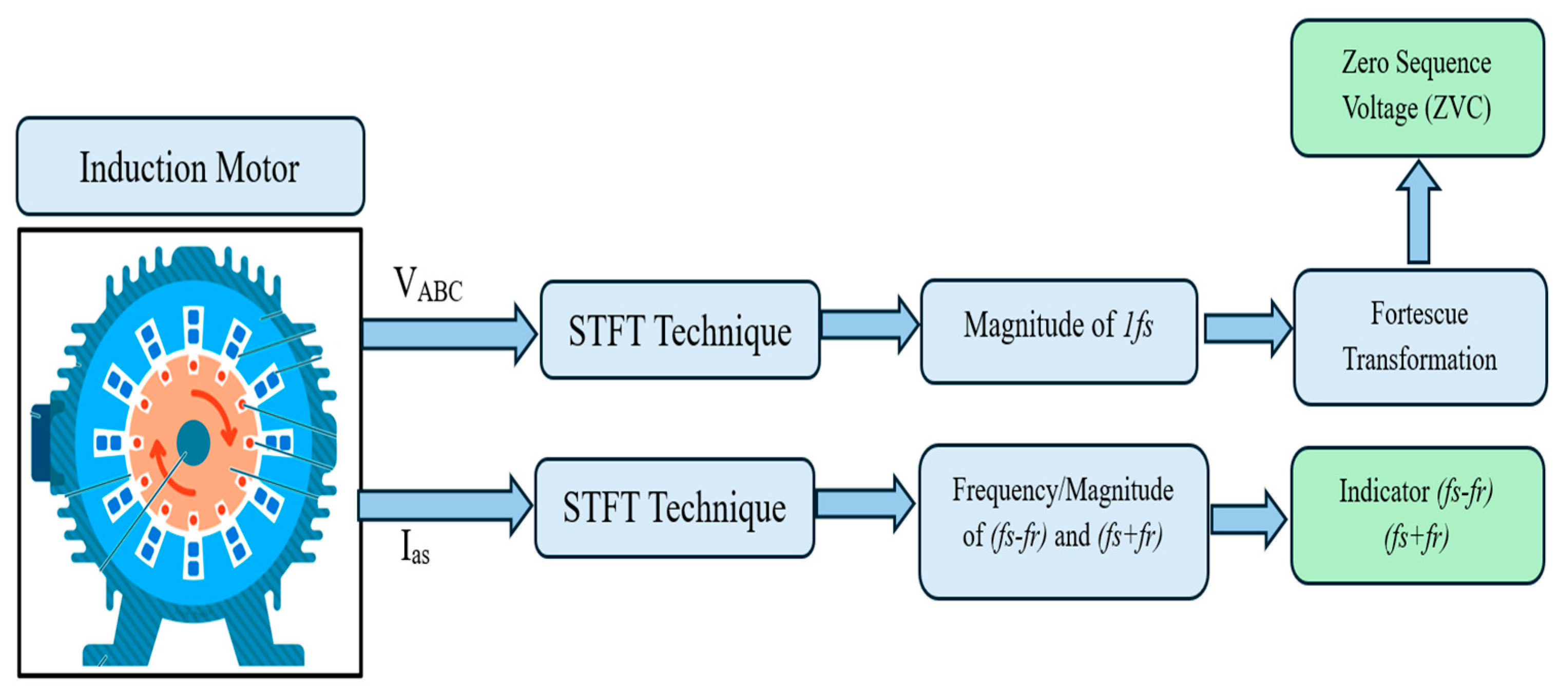
Hence, the proposed approach can be outlined by the following steps (Figure 1).
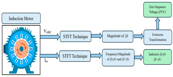
Figure 1.
A description of the proposed method of indicators extraction.
4. The Analysis of the Symmetrical Components
The sequence component analysis is a powerful technique used in the power system analysis to simplify the study of unbalanced three-phase systems [41]. Instead of dealing directly with the three individual phase quantities (voltages or currents), it transforms them into three fictitious quantities called positive-sequence, negative-sequence, and zero-sequence components. Each sequence component represents a different type of imbalance and has unique characteristics that help in understanding and solving problems in power systems.
The occurrence of an ITSC fault within a stator winding disrupts the balanced three-phase system, resulting in measurable imbalances in both stator voltages and currents [42]. These imbalances manifest as non-zero negative- and/or zero-sequence components in the symmetrical component transformation of the stator voltages. Therefore, analyzing these symmetrical components is crucial for the effective detection and diagnosis of ITSC faults, providing a sensitive indicator of this specific fault type.
The symmetrical components (, , ) derived from three unbalanced sets of IM voltages (, , ) can be computed using Fortescue’s complex transformation:
with .
In a healthy state, the symmetrical operation of a three-phase induction motor results in the absence of negative- and zero-sequence voltages; only positive-sequence voltages are present.
When a fault, such as an ITSC fault, occurs, it generates the ZSV. As a result, the ZSV will not be zero when a motor is in a faulty condition.
The key point of the proposed idea is to estimate and track only the fundamental harmonics related to the voltages to compute the required symmetrical components. Therefore, the proposed method can be described by the following steps (Figure 1):
- ✓
- Step 01: The acquisition of the three-phase voltages (Va, Vb, Vc).
- ✓
- Step 02: The fundamental harmonic magnitudes and phase angles of the three-phase voltages are extracted using the short-time Fourier transform (STFT). This signal processing technique accurately estimates and tracks the frequency, amplitude, and phase of each harmonic, accommodating the non-stationary nature of the voltage signals.
- ✓
- Step 03: The calculation of the positive-, negative-, and zero-sequence components related to the supply voltages ()
- ✓
- Step 04: The calculation of the magnitude of the zero-sequence voltage component. Hence, the proposed approach can be outlined by the following steps (Figure 1).
5. Experimental Validation
In this section, the behavior of each indicator will be analyzed under an ITSC fault, alongside the different working conditions. The aim is to test and compare these factors in order to select the best one that allows for the reliable detection of the ITSC fault. The comparative study is evaluated under different machine operating conditions. The experimental setup used for this goal consists mainly of a three-phase, 1.1 kW squirrel-cage induction motor, with star (Y) connections, which is powered by a balanced three-phase, 50 Hz sinusoidal voltage source (Table 1). A controlled voltage unbalance was introduced by a variable rheostat connected upstream of the motor, emulating real unbalanced supply conditions.

Table 1.
IM parameters.
A controllable electromagnetic brake system provided the mechanical load, enabling tests under different load conditions. Real-time voltage and current measurements were acquired using an NI 6036-E Series data acquisition card at a sampling rate of 10 kHz. Figure 2 shows a general view of the experimental test bench.
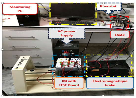
Figure 2.
The general view of the experimental test bench.
To facilitate the control of the introduction of ITSC faults, the stator windings of the induction motor were modified by adding tapings to individual coils. These tapings were connected to external wires routed to a modified terminal box, as shown in Figure 3. This setup allowed for the emulation of ITSC faults with varying severities in any of the three stator phases. The IM stator windings were modified by adding tapings connected to the stator coils. The other ends of these external wires were connected to the motor terminal box, allowing the introduction of ITSC faults with different severities in any stator phase.
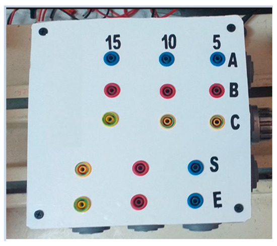
Figure 3.
Induction motor’s modified box with ITSC faults.
Faults were introduced by short-circuiting a predetermined number of turns via the tapings and the external connections at the terminal box. Three different fault severities were investigated, corresponding to short circuits involving 5, 10, and 15 turns. These represent 1.26%, 2.5%, and 3.7% of the total number of stator turns (Ns = 396), respectively.
To make the tests as close to the real case as possible, there was no additional resistance in the short-circuit.
In order to implement the proposed method online, which uses the STFT technique, it was developed using the Matlab code. Then it was inserted into the LabVIEW software using the Matlab script node. The LabVIEW software easily allows the acquisition of a short time window (0.1 s) containing 10,000 samples from the stator voltages and current signals. The acquired samples will be processed by the inserted algorithm. These steps are carried out continuously, which permits us to follow, in real time, the evolution of the target indicators as well as the different motor quantities, such as voltages, currents, impedances, and the symmetrical components and the target harmonics.
The comparative study is performed based on three key criteria: the sensitivity to ITSC faults, robustness under varying load conditions, and robustness against other fault types with similar effects, such as the USV condition.
- A.
- The Sensitivity to the ITSC fault
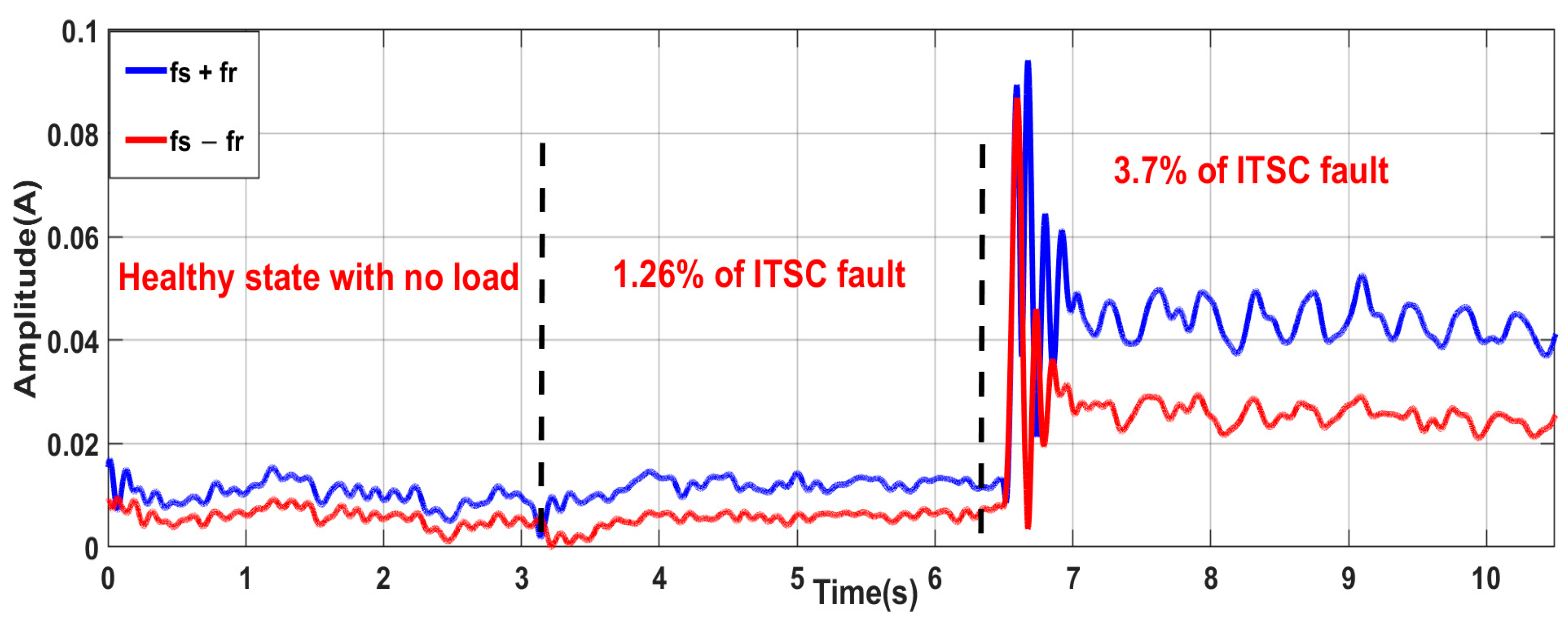
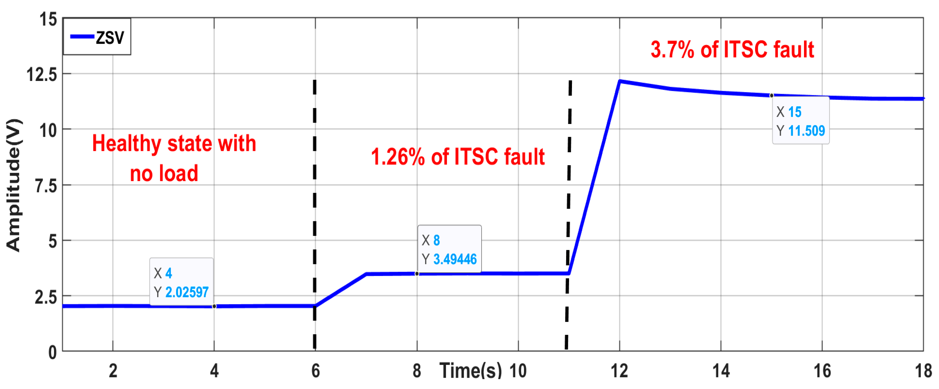
In this section, several tests are carried out in order to study the behavior of the two indicators under successive increases in the ITSC fault severity. First, the test was started with a motor under a balanced supply at no load. After a few seconds, ITSC faults with increasing severity are introduced. This is achieved by introducing ITSC faults affecting 1.26% and then 3.7% of the turns in phase ‘a’. Through these sequential tests, the studied indicators are computed and monitored in real time. The obtained curve is depicted in Figure 4 and Figure 5, whereas Table 2 shows the quantitative assessment of the studied indicators by measuring their amount of change as a function of the number of shorted turns. As it can be clearly seen, the studied indicators are stable and have small amplitudes during the motor operation in its healthy state (due to the motor’s inherent asymmetries). However, the successive occurrences of 1.26% and then 3.7% of the ITSC fault cause instantaneous responses on the studied indicators. Indeed, for the magnitude of harmonics, (fs − fr) = 25 Hz and (fs + fr) = 75 Hz, it is insensible to a low severity of the ITSC fault, and for 3.7% of the ITSC fault it has significantly increased from 0.0071 (A) to 0.025 (A) for (fs + fr) and then for (fs − fr) from 0.0115 (A) to 0.04 (A), which represents an increase of 252.11% and 247%, respectively. The second indicator (ZSV) has significantly increased from 2 (V) to 3.5 (V) and then to 11.5 (V), which represents an increase of 75% and 475%, respectively. This clearly demonstrates the tracking capability of the studied indicators as their amplitude raises each time the severity of the fault raises.
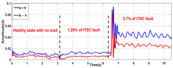
Figure 4.
The amplitude of the harmonics at the frequency (fs − fr) and (fs + fr) response for different severities of ITSC faults.
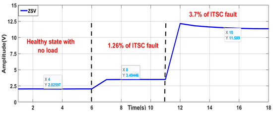
Figure 5.
ZSV response for different severities of ITSC faults.
Table 2.
ZSV values for two different levels of ITSC faults.
- B.
- Robustness against load variation
The previous tests were performed under no mechanical load. The data acquisition of the three-phase-to-neutral voltages and one-phase current started once the motor was operating healthily. A step load change was introduced after a few seconds. Motor load fluctuations are common and affect both motor currents and condition monitoring indicators. A reliable indicator must thus be insensitive to load changes. Additional tests included stepwise load variations to assess the indicators’ performance. Figure 6 illustrates how these step load changes significantly distort the motor current waveforms, producing non-stationary signals.
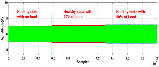
Figure 6.
Three-phase IM currents’ waveforms, assessed for load transient condition.
The curve representing the time evolution of the two indicators is depicted in Figure 7 and Figure 8.
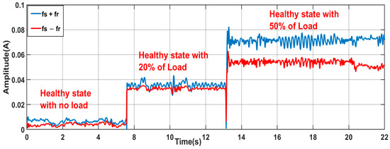
Figure 7.
The amplitude of the harmonics at the frequency (fs − fr) and (fs + fr) under different step load variations.

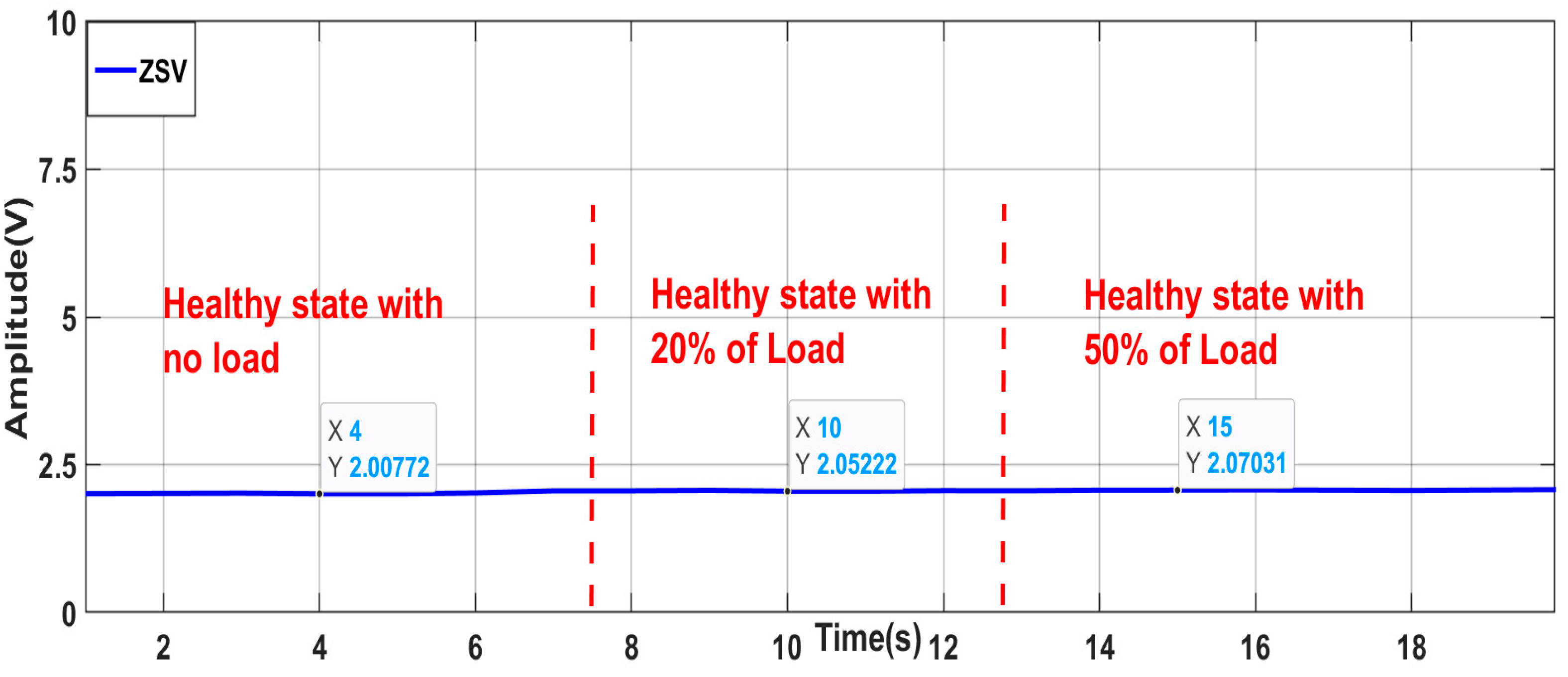
Figure 8.
ZSV behavior under different step load variations.
Figure 7 clearly demonstrates that the magnitudes of the two targeted harmonics (fs − fr) and (fs + fr) varied considerably with changes in the motor load. This sensitivity to load variations suggests that the indicator lacks robustness.
As it can be clearly seen in Figure 8, the motor load variations have no significant effect on the proposed fault indicator (ZSV). This clearly confirms its robustness against load variations.
- C.
- Robustness against similar faults
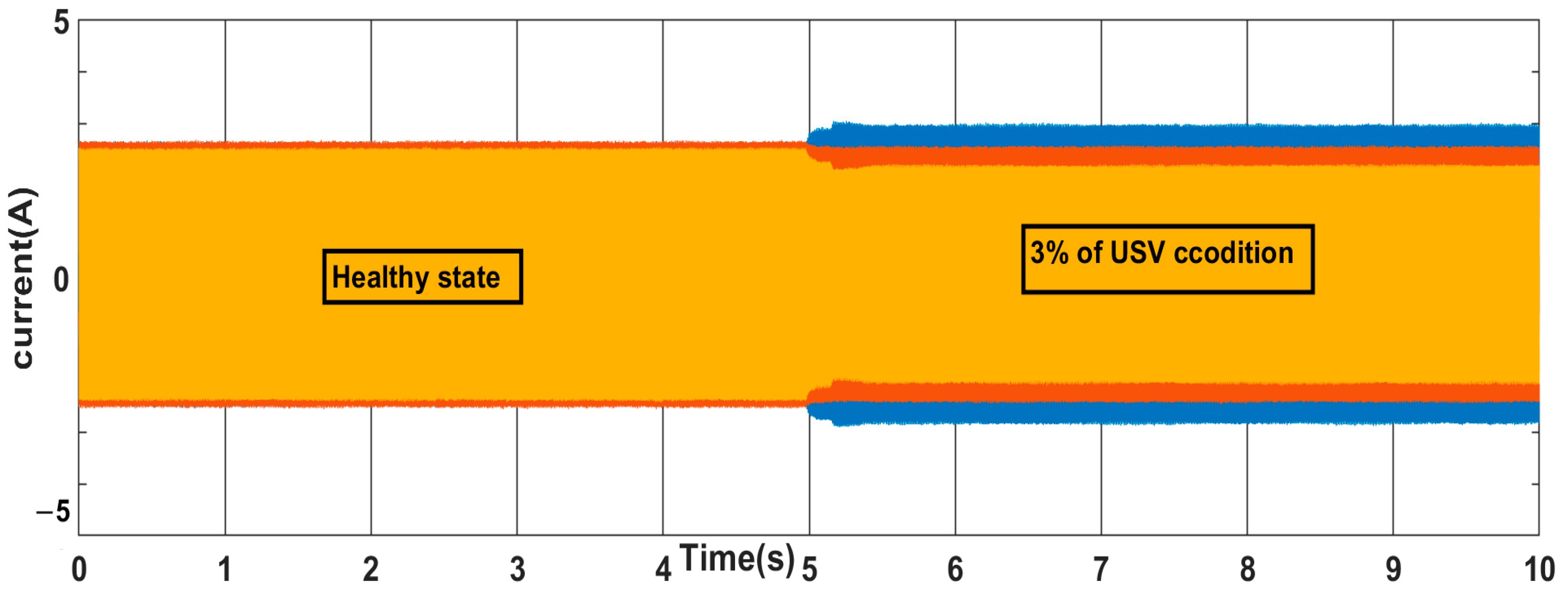
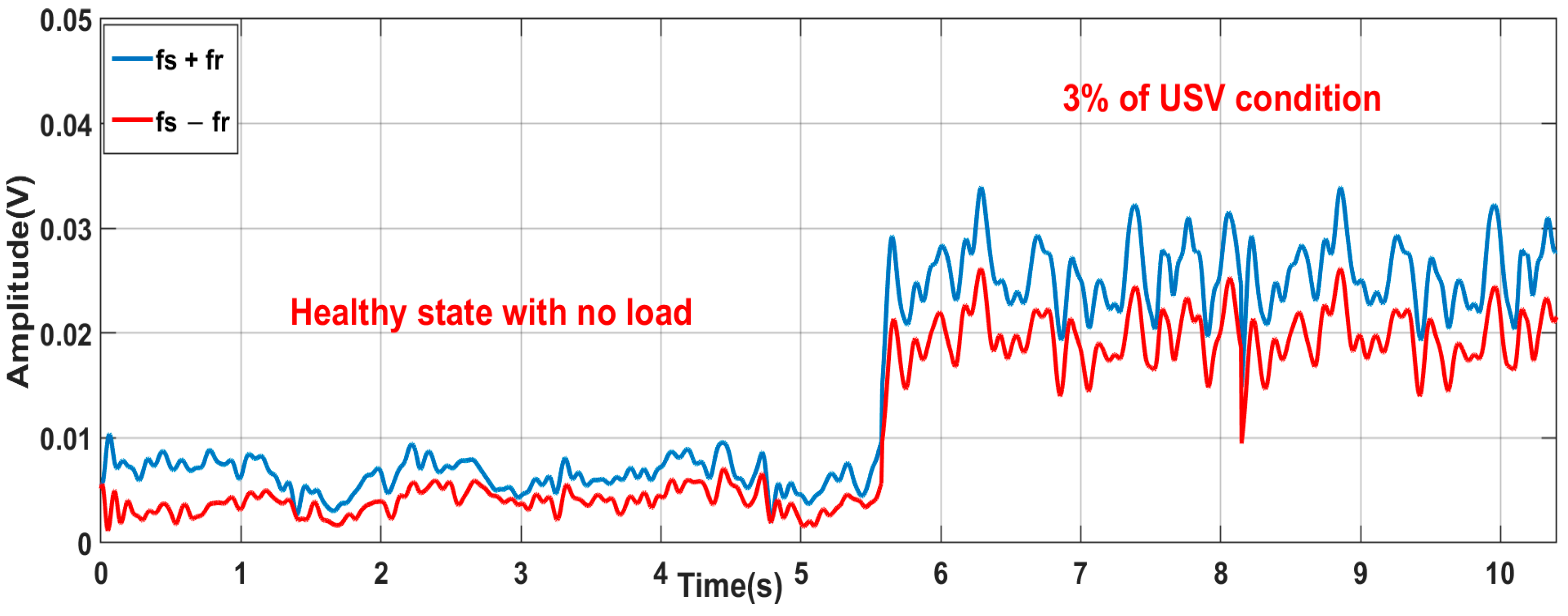
The reliability of any fault indicator should be assessed by its robustness against other faults with similar symptoms. Voltage imbalances in induction motors, like inter-turn short circuits (ITSCs), create imbalances in supply voltages, stator currents, and winding impedances, producing similar effects in the time domain (Figure 9). Therefore, the behavior of the first indicator (magnitude of harmonics (fs − fr) = 25 Hz and (fs + fr) = 75 Hz)) and the second indicator of the ZSV under USV conditions is crucial. To evaluate this, an experiment was conducted with a healthy induction motor under balanced voltage conditions. A 3% USV was then introduced. Figure 10 and Figure 11 display the measured time–domain responses of the amplitude of the harmonics at the frequencies of (fs − fr) and (fs + fr) and ZSV during this test.

Figure 9.
The phase current evolution for an IM in a healthy state and with 3% of the USV condition.
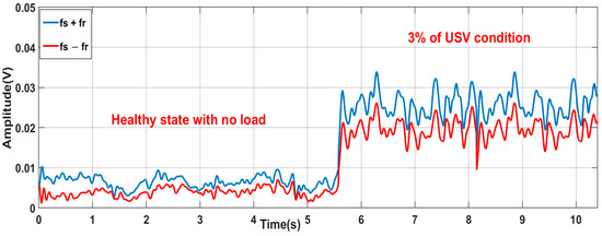
Figure 10.
The amplitude of the harmonics at the frequency (fs − fr) and (fs + fr) reaction under the USV condition.
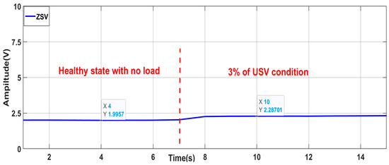
Figure 11.
ZSV evolution under USV conditions.
Figure 10 shows that a 3% USV condition significantly increased the magnitudes of the (fs − fr) and (fs + fr) harmonics in the stator current spectrum. These harmonics resemble those amplified by ITSC faults and load variations, differing only in amplitudes. This similarity in harmonic signatures makes an accurate fault diagnosis difficult using only a spectral analysis. Consequently, distinguishing an ITSC fault from a USV condition is problematic or impossible.
In addition, a series of experiments, progressively increasing USV conditions levels from a healthy operation up to 4% were conducted to evaluate the ZSV indicator’s behavior. The results, presented in Figure 12, show the ZSV’s robustness under these varying USV conditions, as it remained almost constant throughout the test period.
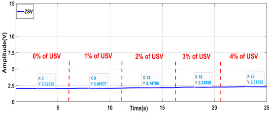
Figure 12.
ZSV evolution under different USV severities.
- D.
- Discussion
Based on the above comparison, it can be concluded that the harmonic amplitudes at (fs − fr) and (fs + fr) exhibit similar magnitudes under various fault conditions (including the ITSC fault, USV condition, and load variation). Nevertheless, it should be taken into account that an increase in these frequency components can also be caused by eccentricity. The research in [43,44,45,46] indicates that mixed eccentricity faults in induction motors produce stator current harmonics identical to those produced by ITSC faults.
Also, the research reported in [6,12,47] indicates that the occurrence of the ITSC fault does not induce new spectral components, but rather amplifies the magnitudes of the TH, EFH, and RSH, which always exist in the stator current spectra even in a healthy state. This gives clarification to the previous conclusions reported in some papers. This study also shows that these spectral symptoms can also be observed due to the load variation or USV condition.
ITSC faults and mixed eccentricity faults have frequency signatures that overlap. The USV condition and load variations also make it hard to tell the difference between faults accurately using only the STFT-based MSCA. These similar signatures render the identified harmonics unsuitable as reliable fault indicators. Consequently, they cannot be considered reliable ITSC fault indicators. The ZSV indicator demonstrates a significant robustness to common operating conditions, like unbalanced voltage and varying loads. This, in contrast to the less reliable harmonic signatures, makes the ZSV a highly suitable indicator for detecting inter-turn short circuits (ITSCs) reliably.
6. ITSC Fault Detection Based on ZSV Under Complex Operating Conditions
In industrial settings, induction motors work in a variety of different and often complicated conditions, such as changing loads, USV conditions, and variable speeds. To test how well the ZSV can find ITSC faults in these real-world situations, two more test scenarios were created.
The first event involves the motor powered by an autotransformer, and the scenario consists of six successive tests, as described below:
- ▪
- Start the motor in a healthy state, with balanced supply voltages, with no load;
- ▪
- Increase the motor load by 50% (the motor is always in a healthy state);
- ▪
- Return to the operation under a motor load of 30% (a healthy motor with a balanced supply);
- ▪
- Introduce a USV of 3% in phase “a”, under 30% of the load (healthy motor);
- ▪
- Short 3.7% of the ITSC fault in phase “a” under a USV of 3% and 30% of the load;
- ▪
- Eliminate the USV while the motor remains with the 3.7% of the ITSC fault and 30% of the load.
The second event involves an induction motor powered by a voltage source inverter (VSI). This reflects the common use of VSIs with scalar control in contemporary industrial motor drives. This control technique directly links the voltage magnitude to frequency, significantly affecting motor voltages and currents, and, consequently, the robustness of a fault indicator. Therefore, a reliable indicator must demonstrate minimal sensitivity to voltage variations induced by changes in the motor speed.
This scenario consists of four successive tests, described as follows:
- ▪
- Start the motor in a healthy state, with 50 Hz, with no load;
- ▪
- Increase the motor load by 30% (healthy motor with 50 Hz);
- ▪
- Decrease the frequency of the motor to 30 Hz (healthy motor at 30% of the load);
- ▪
- Introduce 3.7% of the ITSC fault in phase “a”, under 30% of the load and 30 Hz.
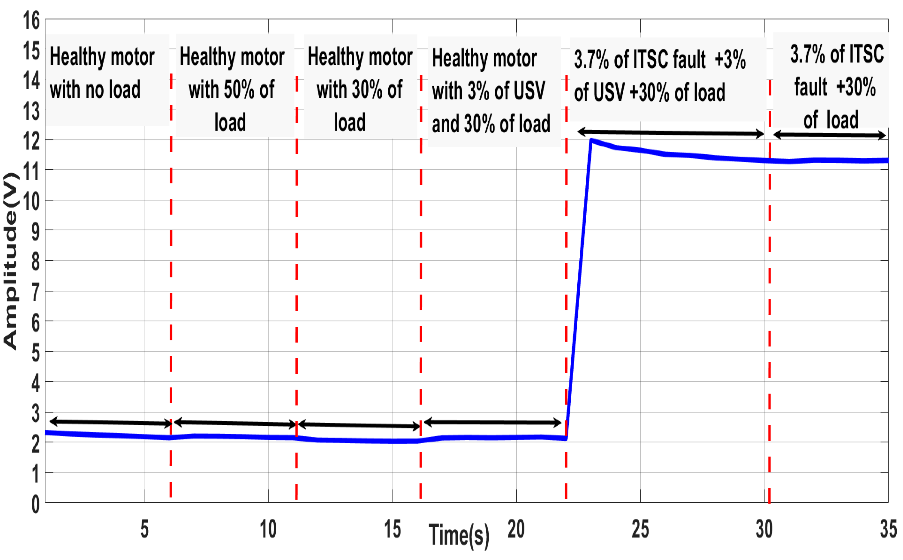
In this study, the proposed algorithm was designed to process only the sampled three-phase voltages, enabling the online calculation and continuous monitoring of the ZSV, as shown in Figure 13 and Figure 14. In the first testing scenario (autotransformer powered), the ZSV demonstrated a near-constant level during the healthy operation and then experienced an abrupt increase following the initiation of the ITSC fault, confirming its value as an effective indicator for these faults, as well as for providing robustness against USV conditions and variations in the load. Tests were also carried out with the motor powered by a voltage source inverter, with a behavior of the ZSV similar to the first test and with half the magnitude. The results obtained under these tests once again demonstrate the effectiveness, reliability, sensitivity, and robustness of the ZSV indicator in the detection of ITSC faults, even under variations in speed. As a result, the condition monitoring systems based on the ZSV are easy to implement experimentally and can work successfully in real time.
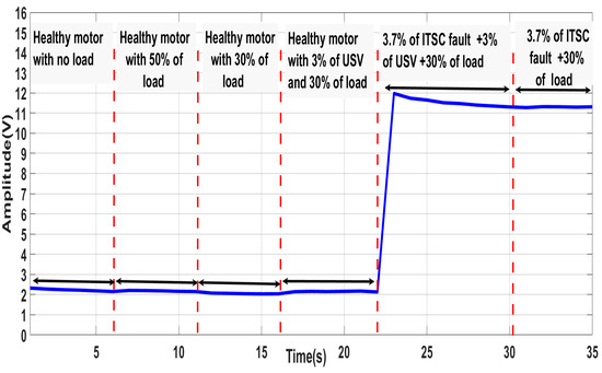
Figure 13.
The online evolution of the ZSV under different operating conditions.
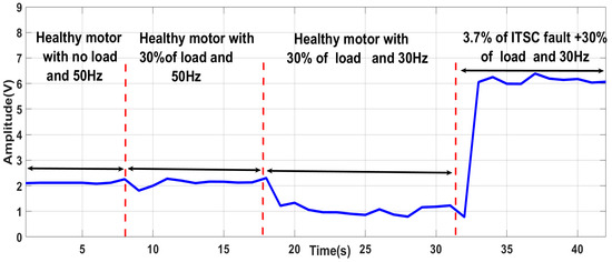
Figure 14.
Online evolution analysis of zero-sequence voltage (ZSV) under different operating conditions with variable speed.
Supported with the diagnostic results attained for each fault diagnostic algorithm, Table 3 establishes a comparison between the MCSA-based STFT method and the ZSV method.
Table 3.
Comparative study between (fs − fr); (fs + fr); and ZSV.
Reliability and accuracy are crucial characteristics in quantitative research. In the context of this study, reliability refers to how consistently the ZSV method measures the fault severity. This is typically assessed using a test–retest methodology, which involves subjecting the proposed method to repeated tests on the same motor under identical conditions at different points in time. These repeated tests should ideally yield consistent results; otherwise, the method would be considered unreliable and potentially inaccurate.
The aforementioned tests were conducted experimentally and online, involving continuous monitoring and multiple repetitions, yielding results that closely matched theoretical expectations. In total, the proposed method has been applied to three different machines (one IM of 3 kW and two of 1.1 kW). These tests were carried out at our laboratory, and qualitatively the same results, observations, and conclusions were reached.
Consequently, the ZSV-based detection strategy has demonstrated a high reliability in terms of the fault detection sensitivity and robustness against load variations or USV conditions. Furthermore, the method is characterized by its simplicity, requiring only the acquisition of readily available three-phase voltages. Therefore, condition monitoring systems based on ZSV are easily implementable experimentally and can operate successfully in real time. Additionally, the proposed method is also expected to be suitable for higher-power motors or other types of electric motors (e.g., multiphase induction machines, permanent-magnet machines, and reluctance machines), and these areas are the focus of ongoing research efforts.
7. Conclusions
This paper presents an online methodology employing the STFT for the extraction of ITSC fault symptoms and the generation of a reliable fault indicator for applications involving induction motors. For the design of this methodology, two potential indicators, namely the magnitude of specific harmonics and the ZSV, were considered. To identify the optimal indicator, an experimental comparative study based on three evaluation criteria (sensitivity to ITSC faults, robustness against load variations, and robustness against other similar faults) was undertaken. The proposed algorithm, which was implemented in the LabVIEW environment, demonstrated its capacity for the real-time computation and continuous display of the indicators. Results obtained from several experimental tests conducted on a 1.1 kW induction motor under a range of operating scenarios demonstrated that the ZSV is largely insensitive to variations in load or the presence of an unbalanced supply voltage (USV) and that, unlike the harmonic magnitudes, the ZSV showed a selective sensitivity to the presence of an ITSC fault.
This paper opens new horizons for future research, including further investigating ZSV’s selectivity against other fault types (eccentricity, broken rotor bars, and impedance asymmetry); evaluating the ZSV performance with different power supply topologies (VSI with vector control); applying artificial intelligence (AI) techniques for automatic decision-making, ITSC fault severity estimations, and potentially fault localization within the stator winding; and extending its applicability beyond three-phase IMs to other machine types.
Author Contributions
Conceptualization, M.H., M.S., and A.J.M.C.; methodology, M.H., M.S., and A.J.M.C.; software, M.H., M.S., and A.A.; validation, M.H., M.S., and A.A.; formal analysis, M.H., M.S., and A.J.M.C.; investigation, M.S.; resources, M.S. and A.J.M.C.; data curation, M.H.; writing—original draft preparation, M.H.; writing—review and editing, A.J.M.C. and M.S.; visualization, M.H. and M.S.; supervision, M.S.; project administration, A.J.M.C.; funding acquisition, A.J.M.C. All authors have read and agreed to the published version of the manuscript.
Funding
This work was supported by the Portuguese Foundation for Science and Technology (FCT) under Projects UIDB/04131/2020 and UIDP/04131/2020.
Data Availability Statement
Data are contained within the article.
Conflicts of Interest
The authors declare no conflicts of interest.
References
- Kumar, S.; Mukherjee, D.; Guchhait, P.K.; Banerjee, R.; Srivastava, A.K.; Vishwakarma, D.N.; Saket, R.K. A Comprehensive Review of Condition Based Prognostic Maintenance (CBPM) for Induction Motor. IEEE Access 2019, 7, 90690–90704. [Google Scholar] [CrossRef]
- Gangsar, P.; Tiwari, R. Signal based condition monitoring techniques for fault detection and diagnosis of induction motors: A state-of-the-art review. Mech. Syst. Signal Process. 2020, 144, 106908. [Google Scholar] [CrossRef]
- Garcia-Calva, T.; Morinigo-Sotelo, D.; Fernandez-Cavero, V.; Romero-Troncoso, R. Early Detection of Faults in Induction Motors—A Review. Energies 2022, 15, 7855. [Google Scholar] [CrossRef]
- Gyftakis, K.N.; Cardoso, A.J.M. Reliable Detection of Stator Interturn Faults of Very Low Severity Level in Induction Motors. IEEE Trans. Ind. Electron. 2021, 68, 3475–3484. [Google Scholar] [CrossRef]
- Bouzid, M.B.K.; Champenois, G. New Expressions of Symmetrical Components of the Induction Motor Under Stator Faults. IEEE Trans. Ind. Electron. 2013, 60, 4093–4102. [Google Scholar] [CrossRef]
- Cherif, H.; Benakcha, A.; Khechekhouche, A.; Menacer, A.; Chehaidia, S.E.; Panchal, H. Experimental diagnosis of inter-turns stator fault and unbalanced voltage supply in induction motor using MCSA and DWER. Period. Eng. Nat. Sci. 2020, 8, 1202–1216. [Google Scholar]
- Dongare, U.V.; Umre, B.S.; Ballal, M.S. Voltage–current locus-based stator winding inter-turn fault detection in induction motors. Int. J. Circuit Theory Appl. 2023, 51, 2889–2911. [Google Scholar] [CrossRef]
- Cardenas-Cornejo, J.-J.; Ibarra-Manzano, M.-A.; González-Parada, A.; Castro-Sanchez, R.; Almanza-Ojeda, D.-L. Classification of inter-turn short-circuit faults in induction motors based on quaternion analysis. Measurement 2023, 222, 113680. [Google Scholar] [CrossRef]
- Alsaedi, M.A. Fault Diagnosis of Three-Phase Induction Motor: A Review. Optics 2015, 4, 1. [Google Scholar] [CrossRef]
- Bahgat, B.H.; Elhay, E.A.; Elkholy, M.M. Advanced fault detection technique of three phase induction motor: Comprehensive review. Discov. Electron. 2024, 1, 9. [Google Scholar] [CrossRef]
- Yakhni, M.F.; Cauet, S.; Sakout, A.; Assoum, H.; Etien, E.; Rambault, L.; El-Gohary, M. Variable speed induction motors’ fault detection based on transient motor current signatures analysis: A review. Mech. Syst. Signal Process. 2023, 184, 109737. [Google Scholar] [CrossRef]
- Sahraoui, M.; Ghoggal, A.; Guedidi, S.; Zouzou, S.E. Detection of inter-turn short-circuit in induction motors using Park–Hilbert method. Int. J. Syst. Assur. Eng. Manag. 2014, 5, 337–351. [Google Scholar] [CrossRef]
- Bahgat, B.H.; Elhay, E.A.; Sutikno, T.; Elkholy, M.M. Revolutionizing motor maintenance: A comprehensive survey of state-of-the-art fault detection in three-phase induction motors. Int. J. Power Electron. Drive Syst. IJPEDS 2024, 15, 1968–1989. [Google Scholar] [CrossRef]
- Pietrzak, P.; Wolkiewicz, M. Stator Winding Fault Detection of Permanent Magnet Synchronous Motors Based on the Short-Time Fourier Transform. Power Electron. Drives 2022, 7, 112–133. [Google Scholar] [CrossRef]
- Zhang, Y.; Ji, T.Y.; Li, M.S.; Wu, Q.H. Application of morphological max-lifting scheme for identification of induction motor stator inter-turn short circuit. CSEE J. Power Energy Syst. 2015, 1, 92–100. [Google Scholar] [CrossRef]
- Surya, G.N.; Khan, Z.J.; Ballal, M.S.; Suryawanshi, H.M. A Simplified Frequency-Domain Detection of Stator Turn Fault in Squirrel-Cage Induction Motors Using an Observer Coil Technique. IEEE Trans. Ind. Electron. 2017, 64, 1495–1506. [Google Scholar] [CrossRef]
- Glowacz, A.; Glowacz, W.; Głowacz, Z.; Kozik, J. Early fault diagnosis of bearing and stator faults of the single-phase induction motor using acoustic signals. Measurement 2017, 113, 1–9. [Google Scholar] [CrossRef]
- Seshadrinath, J.; Singh, B.; Panigrahi, B.K. Investigation of Vibration Signatures for Multiple Fault Diagnosis in Variable Frequency Drives Using Complex Wavelets. IEEE Trans. Power Electron. 2014, 29, 936–945. [Google Scholar] [CrossRef]
- Jia, Z.; Liu, Z.; Vong, C.-M.; Pecht, M. A Rotating Machinery Fault Diagnosis Method Based on Feature Learning of Thermal Images. IEEE Access 2019, 7, 12348–12359. [Google Scholar] [CrossRef]
- Namdar, A.; Nasiri-Gheidari, Z. Detection of Stator Interturn Fault in Induction Motors Using SNR Concept. IEEE Sens. J. 2025, 25, 9925–9933. [Google Scholar] [CrossRef]
- Fotopoulou, M.; Petridis, S.; Karachalios, I.; Rakopoulos, D. A Review on Distribution System State Estimation Algorithms. Appl. Sci. 2022, 12, 11073. [Google Scholar] [CrossRef]
- Tarchała, G.; Wolkiewicz, M. Performance of the Stator Winding Fault Diagnosis in Sensorless Induction Motor Drive. Energies 2019, 12, 1507. [Google Scholar] [CrossRef]
- Godoy, W.F.; Silva, I.N.; Goedtel, A.; Palácios, R.H.C.; Lopes, T.D. Application of intelligent tools to detect and classify broken rotor bars in three-phase induction motors fed by an inverter. IET Electr. Power Appl. 2016, 10, 430–439. [Google Scholar] [CrossRef]
- Abdel-Khalik, A.S.; Hamdy, R.A.; Massoud, A.M.; Ahmed, S. Postfault Control of Scalar (V/f) Controlled Asymmetrical Six-Phase Induction Machines. IEEE Access 2018, 6, 59211–59220. [Google Scholar] [CrossRef]
- Antunes, H.R.P.; Fonseca, D.S.B.; Cardoso, A.J.M. The Use of Line Impedance Symmetrical Components for Stator Faults Diagnostics in Symmetrical Six-Phase Induction Motors. IEEE Trans. Ind. Appl. 2025, 61, 3764–3773. [Google Scholar] [CrossRef]
- Pietrzak, P.; Wolkiewicz, M. Stator winding fault detection of permanent magnet synchronous motors based on the bispectrum analysis. Bull. Pol. Acad. Sci. Tech. Sci. 2022, 70, 140556. [Google Scholar] [CrossRef]
- El-Dalahmeh, M.; Al-Greer, M.; Bashir, I.; El-Dalahmeh, M.; Demirel, A.; Keysan, O. Autonomous fault detection and diagnosis for permanent magnet synchronous motors using combined variational mode decomposition, the Hilbert-Huang transform, and a convolutional neural network. Comput. Electr. Eng. 2023, 110, 108894. [Google Scholar] [CrossRef]
- Du, Y.; Wang, A.; Wang, S.; He, B.; Meng, G. Fault Diagnosis under Variable Working Conditions Based on STFT and Transfer Deep Residual Network. Shock Vib. 2020, 2020, 1274380. [Google Scholar] [CrossRef]
- Almounajjed, A.; Sahoo, A.K.; Kumar, M.K. Diagnosis of stator fault severity in induction motor based on discrete wavelet analysis. Measurement 2021, 182, 109780. [Google Scholar] [CrossRef]
- Iglesias Martínez, M.E.; Antonino-Daviu, J.A.; Dunai, L.; Conejero, J.A.; Fernández De Córdoba, P. Higher-Order Spectral Analysis and Artificial Intelligence for Diagnosing Faults in Electrical Machines: An Overview. Mathematics 2024, 12, 4032. [Google Scholar] [CrossRef]
- Guedidi, A.; Laala, W.; Guettaf, A.; Arif, A. Early detection and localization of stator inter-turn short circuit faults based on variational mode decomposition and deep learning in induction motor. Diagnostyka 2023, 24, 2023401. Available online: https://yadda.icm.edu.pl/yadda/element/bwmeta1.element.baztech-e5ff46fe-d64a-45b5-a474-41f8df649a0e (accessed on 6 February 2024). [CrossRef]
- Pietrzak, P.; Wolkiewicz, M. Comparison of selected methods for the stator winding condition monitoring of a PMSM using the stator phase currents. Energies 2021, 14, 1630. [Google Scholar] [CrossRef]
- Liu, H.; Li, L.; Ma, J. Rolling Bearing Fault Diagnosis Based on STFT-Deep Learning and Sound Signals. Shock Vib. 2016, 2016, 6127479. [Google Scholar] [CrossRef]
- Benkedjouh, T.; Zerhouni, N.; Rechak, S. Deep Learning for Fault Diagnosis based on short-time Fourier transform. In Proceedings of the 2018 International Conference on Smart Communications in Network Technologies (SaCoNeT), El Oued, Algeria, 27–31 October 2018; IEEE: New York, NY, USA, 2018; pp. 288–293. [Google Scholar]
- Laadjal, K.; Sahraoui, M.; Cardoso, A.J.M. On-Line Fault Diagnosis of DC-Link Electrolytic Capacitors in Boost Converters Using the STFT Technique. IEEE Trans. Power Electron. 2021, 36, 6303–6312. [Google Scholar] [CrossRef]
- Delgado-Arredondo, P.A.; Garcia-Perez, A.; Morinigo-Sotelo, D.; Osornio-Rios, R.A.; Avina-Cervantes, J.G.; Rostro-Gonzalez, H.; Romero-Troncoso, R.D.J. Comparative Study of Time-Frequency Decomposition Techniques for Fault Detection in Induction Motors Using Vibration Analysis during Startup Transient. Shock Vib. 2015, 2015, 708034. [Google Scholar] [CrossRef]
- Aguayo-Tapia, S.; Avalos-Almazan, G.; Rangel-Magdaleno, J.D.J.; Ramirez-Cortes, J.M. Physical Variable Measurement Techniques for Fault Detection in Electric Motors. Energies 2023, 16, 4780. [Google Scholar] [CrossRef]
- Niu, G.; Dong, X.; Chen, Y. Motor Fault Diagnostics Based on Current Signatures: A Review. IEEE Trans. Instrum. Meas. 2023, 72, 3520919. [Google Scholar] [CrossRef]
- Hussain, M.; Din Memon, T.; Hussain, I.; Ahmed Memon, Z.; Kumar, D. Fault Detection and Identification Using Deep Learning Algorithms in Induction Motors. Comput. Model. Eng. Sci. 2022, 133, 435–470. [Google Scholar] [CrossRef]
- Almounajjed, A.; Sahoo, A.K.; Kumar, M.K.; Subudhi, S.K. Stator Fault Diagnosis of Induction Motor Based on Discrete Wavelet Analysis and Neural Network Technique. Chin. J. Electr. Eng. 2023, 9, 142–157. [Google Scholar] [CrossRef]
- Rajamany, G.; Srinivasan, S.; Rajamany, K.; Natarajan, R.K. Induction Motor Stator Interturn Short Circuit Fault Detection in Accordance with Line Current Sequence Components Using Artificial Neural Network. J. Electr. Comput. Eng. 2019, 2019, 4825787. [Google Scholar] [CrossRef]
- Bouzid, M.; Champenois, G. A novel reliable indicator of stator windings fault in induction motor extracted from the symmetrical components. In Proceedings of the 2011 IEEE International Symposium on Industrial Electronics, Gdansk, Poland, 27–30 June 2011; IEEE: New York, NY, USA, 2011; pp. 489–495. [Google Scholar] [CrossRef]
- Pons-Llinares, J.; Antonino-Daviu, J.; Roger-Folch, J.; Moríñigo-Sotelo, D.; Duque-Pérez, O. Mixed eccentricity diagnosis in Inverter-Fed Induction Motors via the Adaptive Slope Transform of transient stator currents. Mech. Syst. Signal Process. 2014, 48, 423–435. [Google Scholar] [CrossRef]
- Fernandez-Cavero, V.; Morinigo-Sotelo, D.; Duque-Perez, O.; Pons-Llinares, J. A Comparison of Techniques for Fault Detection in Inverter-Fed Induction Motors in Transient Regime. IEEE Access 2017, 5, 8048–8063. [Google Scholar] [CrossRef]
- Liu, Z.; Zhang, P.; He, S.; Huang, J. A Review of Modeling and Diagnostic Techniques for Eccentricity Fault in Electric Machines. Energies 2021, 14, 4296. [Google Scholar] [CrossRef]
- Liu, Y.; Bazzi, A.M. A review and comparison of fault detection and diagnosis methods for squirrel-cage induction motors: State of the art. ISA Trans. 2017, 70, 400–409. [Google Scholar] [CrossRef] [PubMed]
- Houili, M.; Sahraoui, M.; Laadjal, K.; Cardoso, A.J.M.; Alloui, A. A Comparative Study of MCSA and ZSV-Based Methods for Diagnosing Inter-Turn Short-Circuit Faults in Induction Motors. In Proceedings of the 2024 IEEE International Conference on Artificial Intelligence & Green Energy (ICAIGE), Yasmine Hammamet, Tunisia, 10–12 October 2024; IEEE: New York, NY, USA, 2024; pp. 1–5. Available online: https://ieeexplore.ieee.org/abstract/document/10776654/ (accessed on 12 January 2025).


Disclaimer/Publisher’s Note: The statements, opinions and data contained in all publications are solely those of the individual author(s) and contributor(s) and not of MDPI and/or the editor(s). MDPI and/or the editor(s) disclaim responsibility for any injury to people or property resulting from any ideas, methods, instructions or products referred to in the content. |
© 2025 by the authors. Licensee MDPI, Basel, Switzerland. This article is an open access article distributed under the terms and conditions of the Creative Commons Attribution (CC BY) license (https://creativecommons.org/licenses/by/4.0/).