

Hybrid Damping Mode MR Damper: Development and Experimental Validation with Semi-Active Control


Abstract
1. Introduction
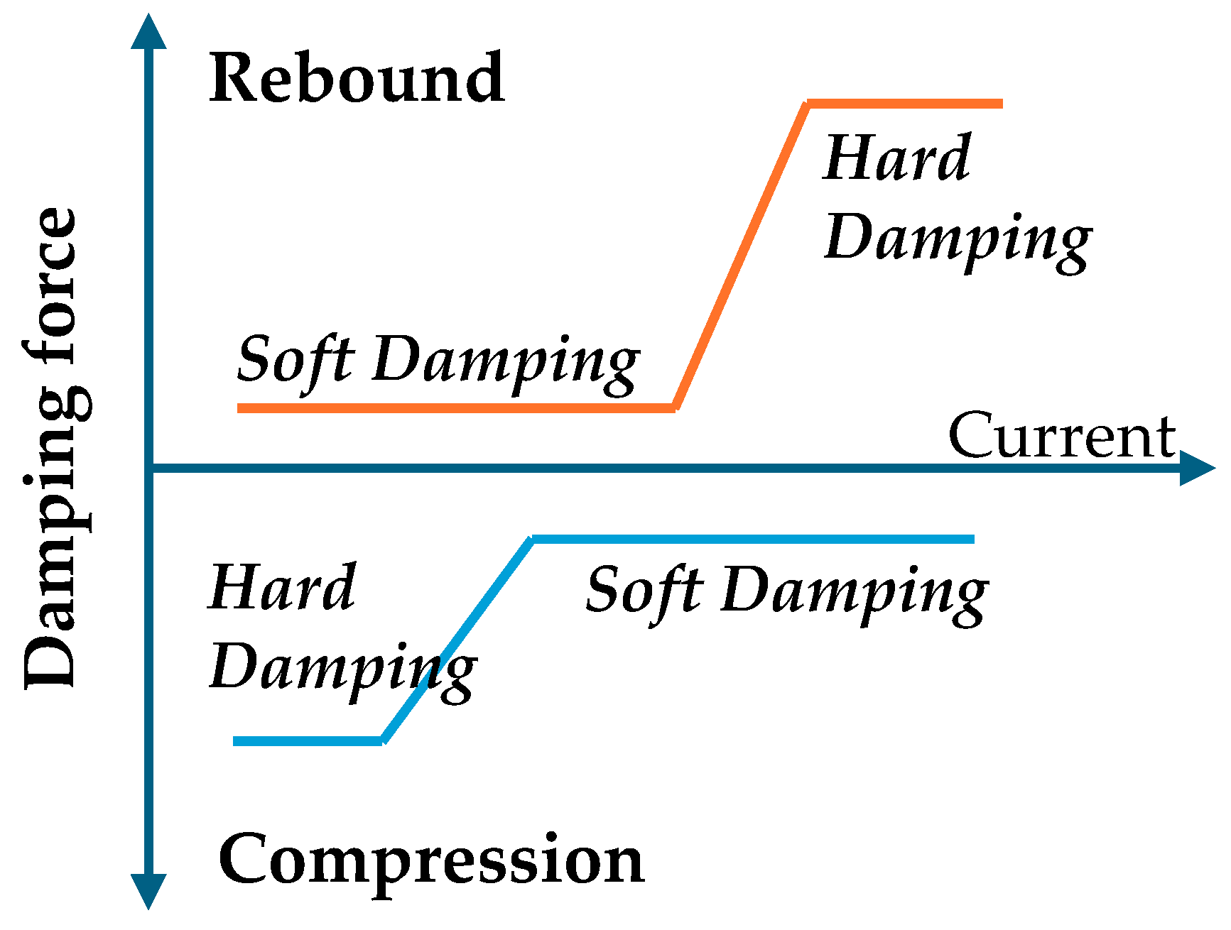
- Independent Control of Rebound and Compression Damping:
- Optimized Electromagnetic Valve Design for Fast Response:
- Integrated Control Logic for Multi-Objective Vehicle Dynamics:
- Experimental Validation of Temperature Sensitivity and Friction Effects:
2. MR Variable Damper Design
2.1. MR Fluid Characteristics
2.1.1. Total Stress
- Flow mode
- Shear mode
- Squeeze mode
2.1.2. Viscosity Properties
2.2. MR Damper Design
2.2.1. MR Valve Design
2.2.2. MR Valve Damping Force
2.3. Damper Design with MR External Valve
3. MR Damper Performance Validation
3.1. Responsiveness and Friction Characteristics
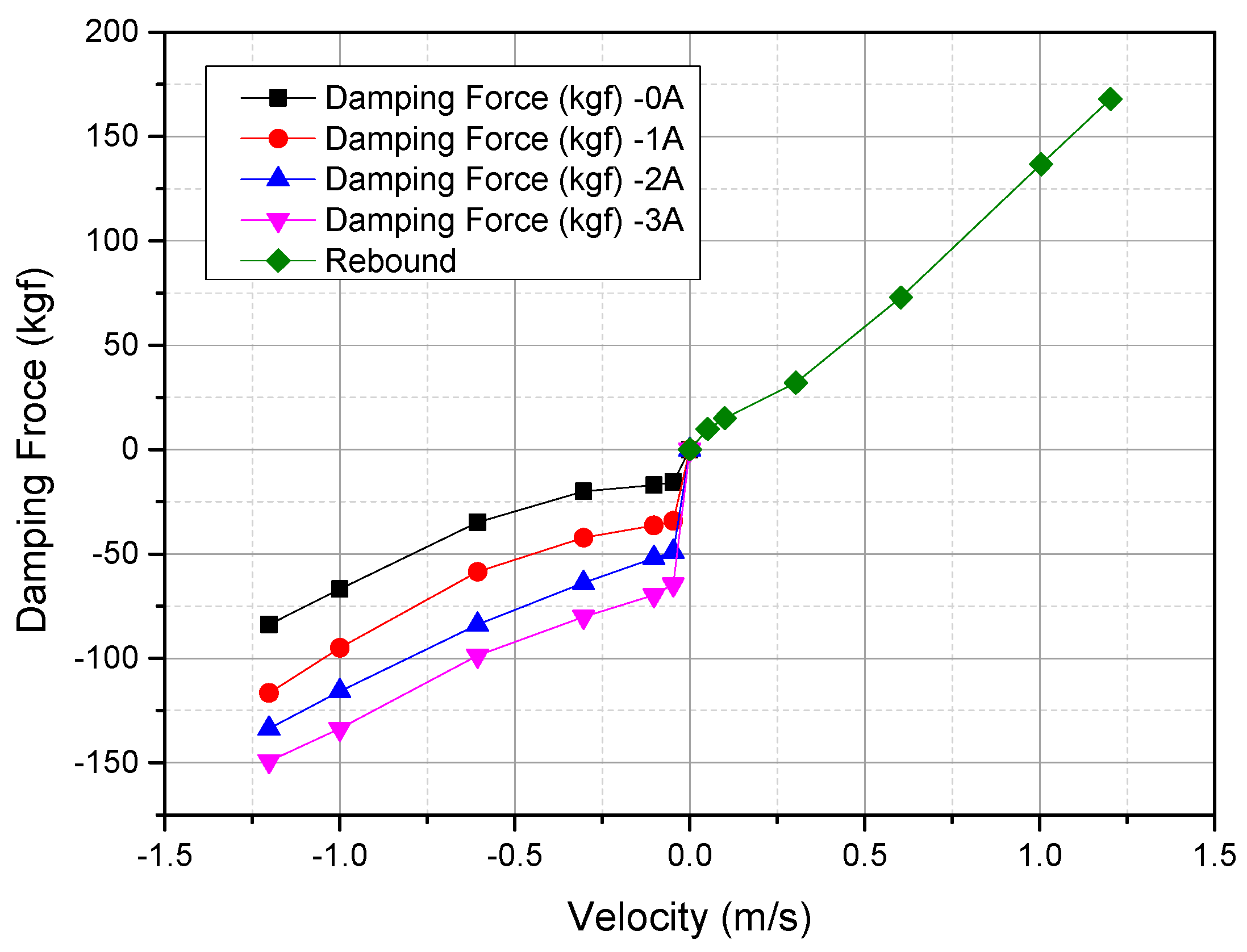
3.2. Damping Force
3.3. Limitations and Optimal Operating Conditions
4. Vehicle Control Logic
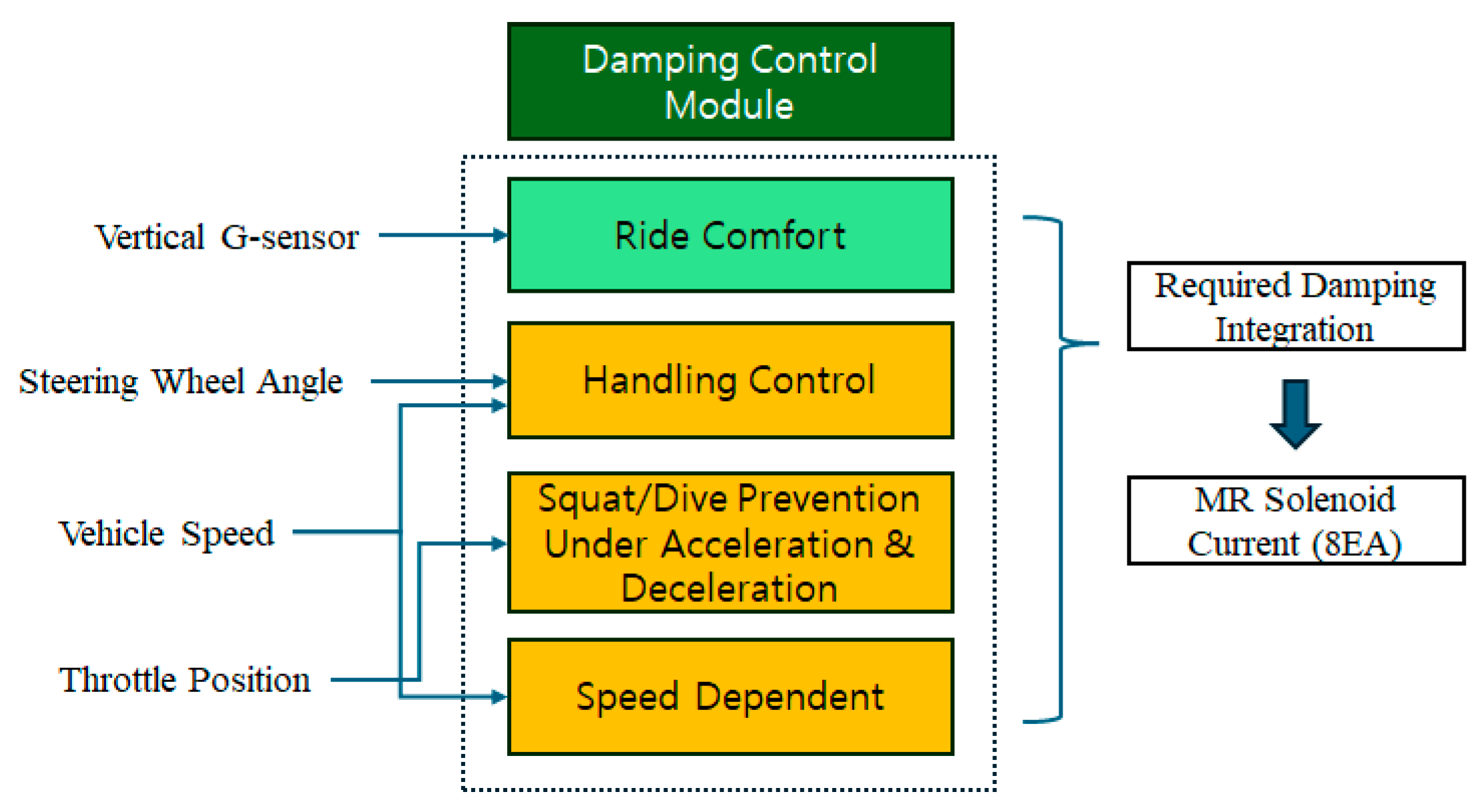
4.1. Overall Function Module
4.1.1. Ride Comfort Logic
- : Current body vertical velocity
- : Low pass filtered absolute body velocity
- : Skyhook gain for each rebound and compression side
4.1.2. Handling Control Logic
- : Vehicle lateral acceleration [m/s2]
- : Vehicle speed [m/s]
- : Wheelbase [m]
- : Vehicle characteristics speed [m/s]
- : Steering wheel angle rate [deg/s]
- : Steering gear ratio
4.1.3. Squat and Dive Prevention Under Acceleration and Deceleration
4.2. Ride Comfort Simlation
4.3. MR Solenod Valve Control
5. Vehicle Test
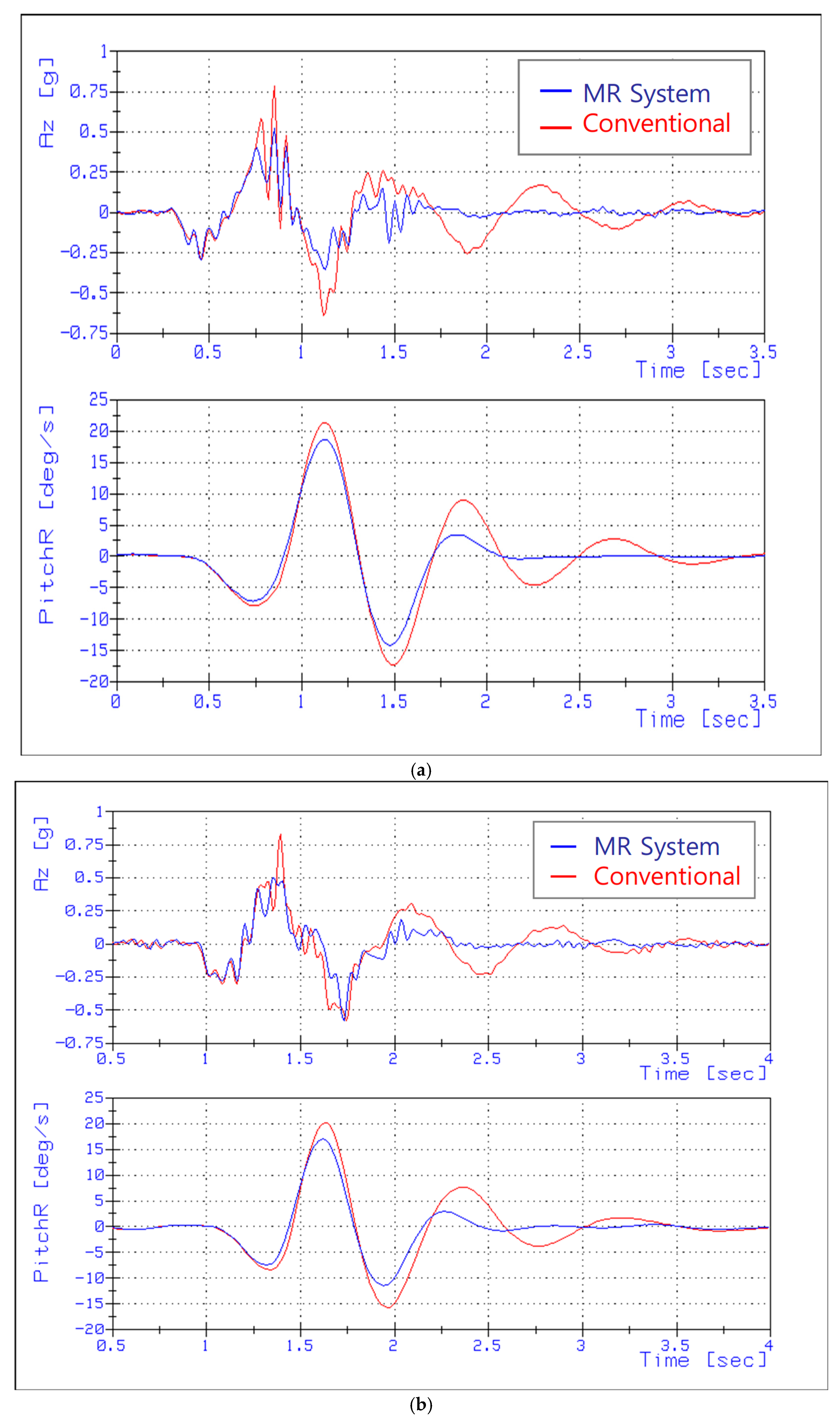
5.1. Ride Comfort
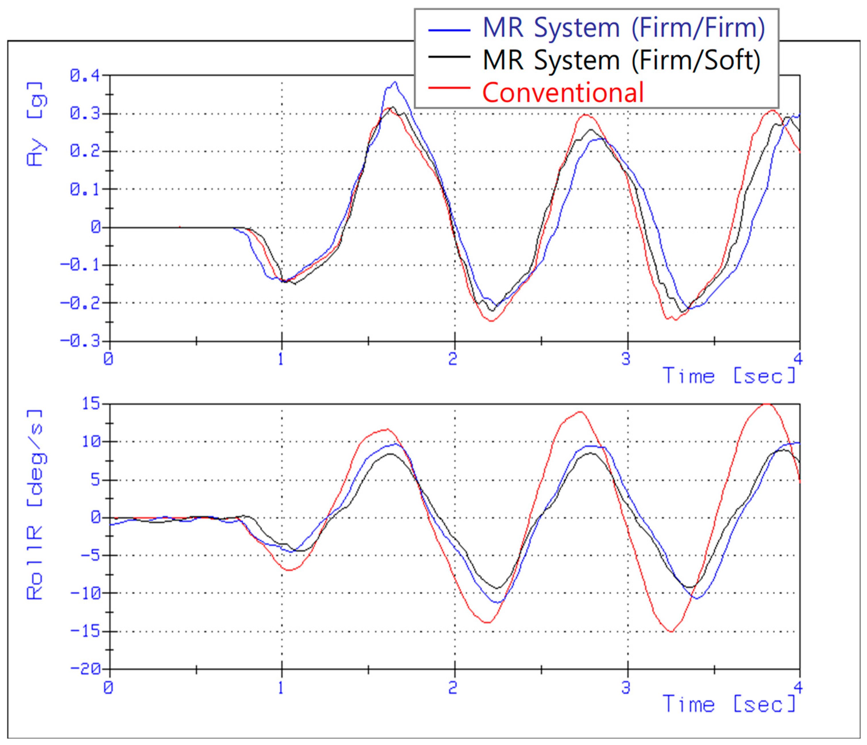
5.2. Handling Performance
5.3. Sudden Acceleration and Deceleration Performance
6. Conclusions and Future Works
Author Contributions
Funding
Data Availability Statement
Acknowledgments
Conflicts of Interest
Nomenclature
| MR Fluid | Magnetorheological Fluid |
| PWM | Pulse Width Modulation |
| TTL | Transistor–Transistor Logic |
| MCU | Micro Controller Unit |
References
- Hrovat, D. Survey of advanced suspension developments and related optimal control applications. Automatica 1997, 33, 1781–1817. [Google Scholar] [CrossRef]
- Choi, S.B.; Lee, S.K.; Park, Y.P. A hysteresis model for the field-dependent damping force of a magnetorheological damper. J. Sound Vib. 2001, 245, 375–383. [Google Scholar] [CrossRef]
- Du, H.; Sze, K.Y.; Lam, J. Semi-active H∞ control of vehicle suspension with magneto-rheological dampers. J. Sound Vib. 2005, 283, 981–996. [Google Scholar] [CrossRef]
- Soliman, A.M.A.; Kaldas, M.M.S. Semi-active suspension systems from research to mass-market–A review. J. Low Freq. Noise Vib. Act. Control 2021, 40, 1005–1023. [Google Scholar] [CrossRef]
- Spencer, B., Jr.; Dyke, S.J.; Sain, M.K.; Carlson, J. Phenomenological model for magnetorheological dampers. J. Eng. Mech. 1997, 123, 230–238. [Google Scholar] [CrossRef]
- Yao, G.Z.; Yap, F.F.; Chen, G.; Li, W.; Yeo, S.H. MR damper and its application for semi-active control of vehicle suspension system. Mechatronics 2002, 12, 963–973. [Google Scholar] [CrossRef]
- Yang, J.; Ning, D.; Sun, S.S.; Zheng, J.; Lu, H.; Nakano, M.; Zhang, S.; Du, H.; Li, W.H. A semi-active suspension using a magnetorheological damper with nonlinear negative-stiffness component. Mech. Syst. Signal Process. 2021, 147, 107071. [Google Scholar] [CrossRef]
- Zhang, H.; Liu, J.; Wang, E.; Rakheja, S.; Su, C.Y. Nonlinear dynamic analysis of a skyhook-based semi-active suspension system with magneto-rheological damper. IEEE Trans. Veh. Technol. 2018, 67, 10446–10456. [Google Scholar] [CrossRef]
- Park, Y.J.; Kang, B.H.; Choi, S.B. A new rotary magnetorheological damper for a semi-active suspension system of low-floor vehicles. Actuators 2024, 13, 155. [Google Scholar] [CrossRef]
- Wang, C.; Zhang, J.; Liu, G.; Shang, H.; Wei, X. Design and performance analysis of a double-outlet-rod magnetorheological damper for impact load. Machines 2022, 10, 1099. [Google Scholar] [CrossRef]
- Zhang, Y.; Guo, J.; Yang, J.; Li, X. Recent structural developments and applications of magnetorheological dampers (MRD): A review. Magnetochemistry 2023, 9, 90. [Google Scholar] [CrossRef]
- Krauze, P. Identification of Control-Related Signal Path for Semi-Active Vehicle Suspension with Magnetorheological Dampers. Sensors 2023, 23, 5770. [Google Scholar] [CrossRef]
- Cao, J.; Liu, P.; Ning, D.; Sun, S.; Liu, G. Vibration control of the seat suspension with a magnetorheological damper-based controllable inerter. J. Vib. Control 2025, 31, 92–103. [Google Scholar] [CrossRef]
- Yang, X.; Li, D.; Li, K.; Xin, Q. Design and experimental study of a new type of electromagnetic radial magnetorheological damper. J. Magn. Magn. Mater. 2025, 618, 172852. [Google Scholar] [CrossRef]
- Wang, H.; Li, D.; Cai, F.; Li, Y.; Wang, J.; Zheng, J. Design and experiment study on a novel magnetorheological impact damper coupled with multiple parallel relief orifices for reducing higher impact peaks. J. Intell. Mater. Syst. Struct. 2025, 36, 242–258. [Google Scholar] [CrossRef]
- Savaia, G.; Corno, M.; Panzani, G.; Sinigaglia, A.; Savaresi, S.M. Temperature Estimation in a Magneto–Rheological Damper. In Proceedings of the 2020 IEEE Conference on Control Technology and Applications (CCTA), Montreal, QC, Canada, 24–26 August 2020; pp. 567–572. [Google Scholar] [CrossRef]
- Iglesias, G.R.; Ahualli, S.; Otero, J.E.; Ruiz-Morón, L.F.; Durán, J.D.G. Theoretical and experimental evaluation of the flow behavior of a magnetorheological damper using an extremely bimodal magnetic fluid. Smart Mater. Struct. 2014, 23, 085028. [Google Scholar] [CrossRef]
- Jamadar, M.E.H.; Devikiran, P.; Desai, R.M.; Kumar, H.; Joladarashi, S. Real-time testing and thermal characterization of a cost-effective magneto-rheological (MR) damper for four-wheeler application. J. Braz. Soc. Mech. Sci. Eng. 2023, 45, 95. [Google Scholar] [CrossRef]
- Kumbhar, M.B.; Desavale, R.G.; Jagadeesha, T. Experimentation and damping performance analysis of a MR damper for resonance control in a quarter car suspension system. J. Vib. Eng. Technol. 2024, 12, 5973–5983. [Google Scholar] [CrossRef]
- El Majdoub, K.; Giri, F.; Chaoui, F.Z. Adaptive backstepping control design for semi-active suspension of half-vehicle with magnetorheological damper. IEEE/CAA J. Autom. Sin. 2020, 8, 582–596. [Google Scholar] [CrossRef]
- Jiang, M.; Rui, X.; Zhu, W.; Yang, F.; Gu, J. Control and experimental study of 6-DOF vibration isolation platform with magnetorheological damper. Mechatronics 2022, 81, 102706. [Google Scholar] [CrossRef]
- Yan, Y.; Dong, L.; Han, Y.; Li, W. A general inverse control model of a magneto-rheological damper based on neural network. J. Vib. Control 2022, 28, 952–963. [Google Scholar] [CrossRef]
- Mousavi, S.H. Modeling and controlling a semi-active nonlinear single-stage vibration isolator using intelligent inverse model of an MR damper. J. Mech. Sci. Technol. 2020, 34, 3525–3532. [Google Scholar] [CrossRef]
- Zapateiro, M.; Pozo, F.; Karimi, H.R.; Luo, N. Semiactive control methodologies for suspension control with magnetorheological dampers. IEEE/ASME Trans. Mechatron. 2011, 17, 370–380. [Google Scholar] [CrossRef]
- Wu, J.; Zhou, H.; Liu, Z.; Gu, M. A load-dependent PWA-H∞ controller for semi-active suspensions to exploit the performance of MR dampers. Mech. Syst. Signal Process. 2019, 127, 441–462. [Google Scholar] [CrossRef]
- Feng, H.; Zhou, Y.; Li, S.; Cheng, G.; Ma, S.; Li, Y. Adaptive Backstepping Control with Time-Delay Compensation for MR-Damper-Based Vehicle Seat Suspension. Actuators 2025, 14, 178. [Google Scholar] [CrossRef]
- Diaz-Choque, C.S.; Felix-Herran, L.C.; Galluzzi, R.; Cespi, R.; Lozoya-Santos, J.D.J.; Ramirez-Mendoza, R.A. Adaptive Control Strategy for Automotive Magnetorheological Dampers Based on Artificial Neural Networks. IEEE Access 2025, 13, 60455–60469. [Google Scholar] [CrossRef]
- Tang, X.; Du, H.; Sun, S.; Ning, D.; Xing, Z.; Li, W. Takagi–Sugeno fuzzy control for semi-active vehicle suspension with a magnetorheological damper and experimental validation. IEEE/ASME Trans. Mechatron. 2016, 22, 291–300. [Google Scholar] [CrossRef]
- Tharehalli Mata, G.; Mokenapalli, V.; Krishna, H. Performance analysis of MR damper based semi-active suspension system using optimally tuned controllers. Proc. Inst. Mech. Eng. Part D J. Automob. Eng. 2021, 235, 2871–2884. [Google Scholar] [CrossRef]
- Kasprzyk, J.; Wyrwał, J.; Krauze, P. Automotive MR Damper Modeling for Semi-Active Vibration Control. In Proceedings of the 2014 IEEE/ASME International Conference on Advanced Intelligent Mechatronics, Besançon, France, 8–11 July 2014; IEEE: Piscataway, NJ, USA, 2014. [Google Scholar]
- Oliveira, F.; Botto, M.A.; Morais, P.; Suleman, A. Semi-active structural vibration control of base-isolated buildings using magnetorheological dampers. J. Low Freq. Noise Vib. Act. Control 2018, 37, 565–576. [Google Scholar] [CrossRef]
- Gad, A.S.; Ata, W.G.; El-Zomor, H.M.; Jabeen, S.D. Optimizing Driver Comfort: Magnetorheological Damper Seat Suspension for Internal Combustion and Electric Vehicles Under Uncertain Conditions. J. Vib. Eng. Technol. 2025, 13, 157. [Google Scholar] [CrossRef]
- Wang, M.; Pang, H.; Luo, J.; Liu, M. On an enhanced back propagation neural network control of vehicle semi-active suspension with a magnetorheological damper. Trans. Inst. Meas. Control 2023, 45, 512–523. [Google Scholar] [CrossRef]
- Wang, C.; Cheng, W.; Zhang, H.; Dou, W.; Chen, J. An immune optimization deep reinforcement learning control method used for magnetorheological elastomer vibration absorber. Eng. Appl. Artif. Intell. 2024, 137, 109108. [Google Scholar] [CrossRef]
- Wang, Z.; Liu, C.; Zheng, X.; Zhao, L.; Qiu, Y. Advancements in Semi-Active Automotive Suspension Systems with Magnetorheological Dampers: A Review. Appl. Sci. 2024, 14, 7866. [Google Scholar] [CrossRef]
- Gavin, H.; Hoagg, J.; Dobossy, M. Optimal design of MR dampers. In Proceedings of the US-Japan Workshop on Smart Structures for Improved Seismic Performance in Urban Regions, Seattle, WA, USA, 14 August 2001; pp. 225–236. [Google Scholar]
- Imaduddin, F.; Mazlan, S.A.; Zamzuri, H. A design and modelling review of rotary magnetorheological damper. Mater. Des. 2013, 51, 575–591. [Google Scholar] [CrossRef]
- Viadero-Monasterio, F.; Meléndez-Useros, M.; Jiménez-Salas, M.; Boada, B.L. Robust Static Output Feedback Control of a Semi-Active Vehicle Suspension Based on Magnetorheological Dampers. Appl. Sci. 2024, 14, 10336. [Google Scholar] [CrossRef]
- Hong, K.S.; Sohn, H.C.; Hedrick, J.K. Modified skyhook control of semi-active suspensions: A new model, gain scheduling, and hardware-in-the-loop tuning. J. Dyn. Sys. Meas. Control 2002, 124, 158–167. [Google Scholar] [CrossRef]
- Rajamani, R.; Hedrick, J.K. Semi-active suspensions-a comparison between theory and experiments. Veh. Syst. Dyn. 1992, 20, 504–518. [Google Scholar] [CrossRef]
- Yoon, Y.H.; Choi, M.J.; Kim, K.H. Development of a reverse continuous variable damper for semi-active suspension. Int. J. Automot. Technol. 2002, 3, 27–32. [Google Scholar]


| Symbol | Value | Unit | Description |
|---|---|---|---|
| 427.5 | kg | Front sprung mass | |
| 251 | kg | Rear sprung mass | |
| 41.5 | kg | Unsprung mass | |
| 443 | kg∙m2 | Pitch moment of inertia | |
| 38,000 | Ns/m | Equivalent front spring stiffness | |
| 18,000 | Ns/m | Equivalent rear spring stiffness | |
| 211,800 | N/deg | Tire vertical stiffness | |
| 97,500 | N/deg | Rear tire cornering stiffness | |
| 1.483 | m | Distance from center of gravity to front axle | |
| 1.5189 | m | Distance from center of gravity to rear axle |
Disclaimer/Publisher’s Note: The statements, opinions and data contained in all publications are solely those of the individual author(s) and contributor(s) and not of MDPI and/or the editor(s). MDPI and/or the editor(s) disclaim responsibility for any injury to people or property resulting from any ideas, methods, instructions or products referred to in the content. |
© 2025 by the authors. Licensee MDPI, Basel, Switzerland. This article is an open access article distributed under the terms and conditions of the Creative Commons Attribution (CC BY) license (https://creativecommons.org/licenses/by/4.0/).
Share and Cite
Lee, J.; Oh, K. Hybrid Damping Mode MR Damper: Development and Experimental Validation with Semi-Active Control. Machines 2025, 13, 435. https://doi.org/10.3390/machines13050435
Lee J, Oh K. Hybrid Damping Mode MR Damper: Development and Experimental Validation with Semi-Active Control. Machines. 2025; 13(5):435. https://doi.org/10.3390/machines13050435
Chicago/Turabian StyleLee, Jeongwoo, and Kwangseok Oh. 2025. "Hybrid Damping Mode MR Damper: Development and Experimental Validation with Semi-Active Control" Machines 13, no. 5: 435. https://doi.org/10.3390/machines13050435
APA StyleLee, J., & Oh, K. (2025). Hybrid Damping Mode MR Damper: Development and Experimental Validation with Semi-Active Control. Machines, 13(5), 435. https://doi.org/10.3390/machines13050435