Article

Development of an Innovative Magnetorheological Gearbox for Positioning Control and Anti-Disturbance of a Robotic Arm

1
School of Electrical Engineering and Automation, Anhui University, Hefei 230039, China
2
CAS Key Laboratory of Mechanical Behavior and Design of Materials, Department of Precision Machinery and Precision Instrumentation, University of Science and Technology of China, Hefei 230027, China
3
Institute of Deep Space Sciences, Deep Space Exploration Laboratory, Hefei 230027, China
4
School of Electrical, Computer & Telecommunications Engineering, University of Wollongong, Wollongong 2522, Australia
5
CAS Key Laboratory of Mechanical Behavior and Design of Materials, Department of Modern Mechanics, University of Science and Technology of China, Hefei 230027, China
6
School of Mechanical, Materials, Mechatronic, and Biomedical Engineering, University of Wollongong, Wollongong 2522, Australia
*
Authors to whom correspondence should be addressed.
These authors contributed equally to this work.
Machines 2025, 13(1), 56; https://doi.org/10.3390/machines13010056
Submission received: 28 November 2024 / Revised: 8 January 2025 / Accepted: 10 January 2025 / Published: 15 January 2025
(This article belongs to the Special Issue Adaptive Control Using Magnetorheological Technology)

Abstract

:
The robotic arm is a critical component of modern industrial manufacturing. However, its positioning performance can be hindered by overshooting and oscillation. External disturbances, including collisions or impacts with other objects, can also affect its accuracy and precision. To resolve this problem, this work integrates a compact magnetorheological (MR) bearing, which is capable of switching between locking and unlocking states utilizing the MR effect, into the gearbox of the actuation system of the robotic arm. This integration enables the gearbox (referred to as the MR gearbox) to exhibit variable damping characteristics. This controllable damping property will play an important role in improving the positioning accuracy by offering additional damping. In this study, the MR gearbox was first designed and prototyped. A characterization test was then conducted to verify its variable damping property. The classic Bouc–Wen model was used to describe the MR gearbox and then a mathematical model was established for the whole robotic arm. Additionally, a new variable damping control method was proposed for further improving the positioning precision and reducing energy consumption. As follows, the positioning and the anti-disturbance performances of the robotic arm system installed with the MR gearbox were assessed through numerical simulations and experimental tests. The result shows that the robotic arm under the new control method achieves reductions of 11.76% in overshoot, 14.73% in settling time, and 26.1% in energy consumption compared to the uncontrolled case under the step trajectory, indicating improved positioning performance.

1. Introduction

Robotic arms are usually programmable mechanical arms with similar functions to human’s [1,2,3,4,5]. They can execute repetitive tasks in place of a human with fast response, high reliability and accuracy, increasing working efficiency and productivity as well as keeping workers from hazardous situations to avoid potential injuries. Usually, robotic arms are widely used in industrial production lines to complete tasks such as device assembly, material handling, pick and place, welding and sorting, all of which require a high standard of positioning precision to guarantee manufacturing accuracy. However, overshoot and oscillations are always generated when a robotic arm is instructed to move to a desired position, which adversely influences its positioning accuracy and efficiency. In addition, robotic arms may also suffer external disturbances such as unexpected forces or torques. These external disturbances can result in reduced accuracy and stability or lead to safety hazards such as collisions with nearby objects or individuals. Therefore, effective solutions have to be explored to mostly minimize the overshoot, avoid the oscillations, and strengthen the anti-disturbance capability to the largest extent.
The core component of a robotic arm that influences the positioning and anti-disturbance performance is the actuation system, which consists of the motor and the gearbox. The motor outputs actuation torque, while the gearbox is responsible for amplifying the torque, making it possible to obtain a large output using a small motor. Precise motor control is pivotal for the robotic arm to execute required tasks successfully. In this regard, numerous methods have been put forward to address this challenge. Cio [6] combined stereovision and eye-tracking to control an assistive robotic arm, especially in scenarios where obstacles are present. Kareemullah [7] employed the Internet of Things to enable remote control of robotic arms, reducing human exposure to hazardous environments. Jeong [8] developed a brain-controlled robotic arm system using deep learning and electroencephalogram signals. Comprehensive reviews on the robotic arm control can be found in [9,10]. In terms of the specific purpose for improving the positioning performance of the robotic arm, considerable effort has been devoted by many research groups, where developing advanced control algorithms to control motors is one of the most common methods. For instance, Malki et al. [11] designed a Fuzzy PID control for a flexible-joint robotic arm considering the time-varying loads. The variable gains in the controller enable the arm to perform a faster response with smaller overshoots than its conventional counterpart. Nguyen et al. [12] designed an adaptive sliding controller in which a PID controller works as a compensator to manipulate a robotic arm. Other control algorithms, such as nonlinear model predictive control schemes and neural network algorithms, have also been proven to be effective in improving the positioning performance as well as tracking the performance of robotic arms by controlling motors [13,14,15,16,17].
Nevertheless, for those robotic arms equipped with only motors and gearboxes, the positioning performance is severely limited by the maximum torque that the motors can achieve, even if under effective control algorithms. This maximum torque has a big impact on positioning accuracy as its effect is to pull the arm to the target position when overshoots occur. Therefore, for those situations where the robotic arm is heavily loaded or the maximum torque is relatively small compared to the load, the robotic arm will perform terribly in positioning, resulting in large overshoots and long settling times. Hence, integrating additional devices that can add extra torque into the robotic arm system has been put forward. One typical device is the MR damper, a kind of smart device containing MR Fluids (MRF) [18,19,20]. By regulating the applied magnetic field, the damping of MR dampers can be controlled rapidly and reversibly with low energy consumption [21,22,23]. As the damping torque provided by MR dampers is in the reverse direction of the movement, it will provide extra torque to pull the arm towards the target position, thereby reducing the overshoot and shortening the oscillation time. For example, Ahn et al. [24] developed a pneumatic muscle robotic arm in which an MR brake was equipped on the arm’s joint. Large damping was implemented to reduce the overshoot and oscillation when the manipulator reached the desired position. Similar methods of utilizing MR dampers in robotic arms to improve positioning performance have been verified [25,26].
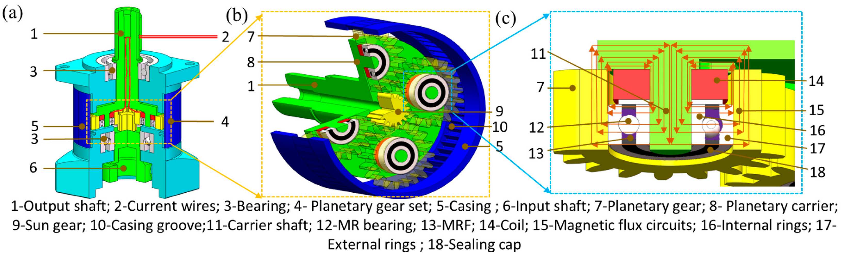
However, one notable issue is that the bulky structure of MR dampers adds considerable complexity and cost to the actuation system, making the robotic arm not practical for real-world applications. Given that the gearbox is indispensable to the actuation system of a robotic arm and that adding variable damping characteristics is the key idea to significantly improving the positioning performance, this work develops an MR gearbox with built-in variable damping capability, which directly endows the actuation system itself with variable damping characteristics, thereby avoiding the need for introducing additional bulky devices. The core structure of the MR gearbox is the MR bearing, which will lock or unlock the carrier shaft and the gear under the control of the magnetic field. It is this locking effect that endows the MR gearbox with damping controllability. When the robotic arm tends to deviate from the target position, the MR gearbox outputs large damping to hinder this deviation; for the other situation where the arm tries to reach the target position, the MR gearbox performs the minimum torque so that the arm approaches the target position as fast as possible. Therefore, this new design will greatly reduce the overshoot and shorten the settling time. Additionally, this built-in structure enables the MR gearbox to be compact and lightweight, and the utilization of the MR device would greatly reduce energy consumption. Those advantages in performance and structure not only improve the arm’s positioning precision but also significantly enhance its practicability.
The rest of the article is organized as follows. Section 2 presents the structural design and working principle of the proposed MR gearbox. Its characterization tests and mathematical modeling are also performed. As follows, a robotic arm system equipped with the MR gearbox is introduced in 
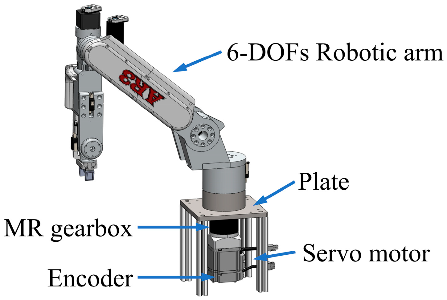
Section 3, with the positioning and anti-disturbance performances of the system being numerically evaluated. In 
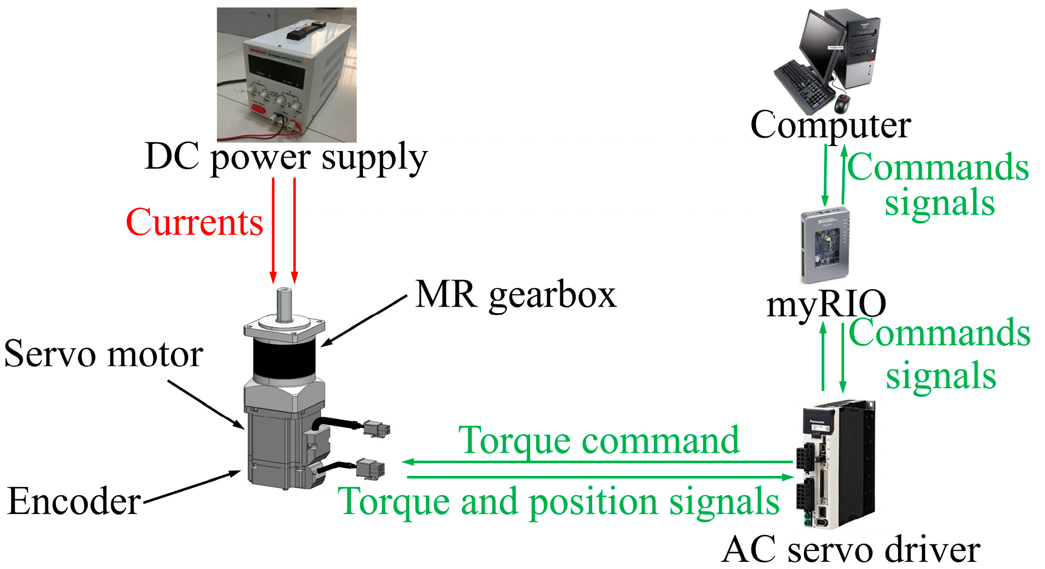
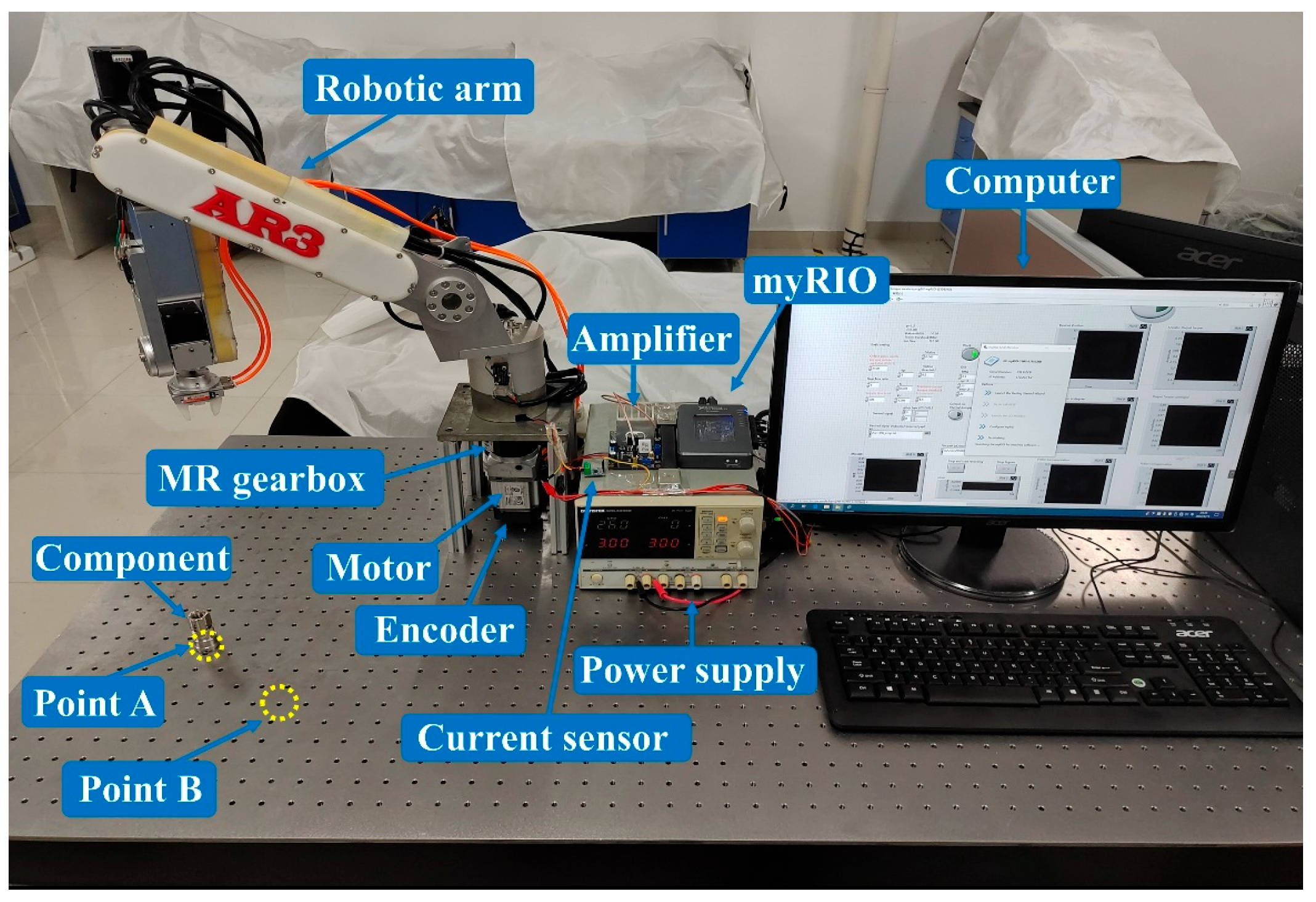
Section 4, the experimental testing setup is demonstrated, and the experimental evaluation is presented. Finally, the conclusion is drawn in Section 5.

2. Design, Characterization and Modelling of the MR Gearbox

2.1. Structural Design and Working Principle

Figure 1a shows the 3D model of the proposed MR gearbox. It mainly consists of input and output shafts (#6 and 1), a planetary gear set (#4), two bearings (#3), and a casing (#5). As the core component of the MR gearbox, the planetary gear set is magnified and presented in Figure 1b. It is comprised of a sun gear (#9), four planetary gears (#7), a planetary carrier (#8), and a casing groove (#10). The casing groove with inward-facing teeth is embedded in the internal surface of the casing, and it acts as a ring gear in the planetary gear set. The planetary gears mesh with the sun gear and the casing groove for the torque transmission between them. To clearly demonstrate the internal design, one of the planetary gears is also magnified and shown in Figure 1c. It is seen that the gear (#7) is connected to the carrier shaft (#11) with an MR bearing (#12) in between. The internal ring (#16) and the external ring (#17) of the MR bearing are fixed with the carrier shaft and the planetary, respectively. The most significant difference of this MR bearing is that it has MRF (#13, MRF-140CG, Lord Corp., Cary, NC, USA) filled all the chambers formed by the internal ring (#16), external ring (#17) and sealed caps (#18). Above the MRF bearing, a set of electromagnetic coils (#14) is also fixed to the carrier shaft, providing a magnetic field to the MRF. The magnetic circuit is presented by the red vector line (#15, Figure 1c). Four sets of electromagnetic coils for the four planetary gears are connected in series with the wire (#2, Figure 1a) going out through the hole in the output shaft. Given the smart nature of the MRF, the MR bearing plays a significant role in controlling the relative motion between the planetary gear and the carrier shafts.
When a motor drives the input shaft, the sun gear rotates accordingly, driving the planetary gears to rotate along the inside teeth of the casing groove through the gear meshing. Consequently, the planetary carrier and the output shaft rotate reversely. In this way, the torque is transferred from the input shaft to the output shaft.
The MR gearbox acts as a conventional planetary gearbox when no current is applied. In this case, MRF behaves with Newtonian fluid characteristics, which means the internal and external rings of the MR bearing can rotate freely to each other. As the internal and external rings are fixed to the carrier shafts and the gears, respectively, free relative motion between the shaft and the gears is consequently unrestricted. However, MRF will perform the MR effect once the electromagnetic coil is powered. This means the yield stress of MRF will increase dramatically, resulting in the restriction on the relative motion between the internal and external rings. This then further causes locking between the gears and the shafts. Under this situation, the MR bearing performing the locking effect enables the MR gearbox to demonstrate increased damping. The higher the applied current, the larger the damping. Therefore, the damping of the MR gearbox can be controlled in real-time by regulating the applied current. With this controllable characteristic, the MR gearbox is able to control the motion and the positioning of the robotic arm more accurately.
As the reasonable distribution of magnetic fields is the key to the successful control of the MR gearbox, magnetic field simulation was conducted using COMSOL 5.5 Multiphysics. Figure 2a shows the result when the coil (100 turns, 0.2 mm diameter, 14.3 Ω) is supplied with a current of 1.0 A. It is seen that magnetic circuits indicated by red arrows have been generated, and the magnetic flux perpendicularly passes the MR bearings. The mean magnetic flux density of the areas in between the bearing’s balls and the internal ring is presented in Figure 2b, which is obtained by averaging the magnetic flux density readings of 10 probes shown in Figure 2a. It is noticed that the mean magnetic flux density increases linearly with respect to the current until the current reaches 0.6 A, after which saturation is observed. In addition, 1.0 A current yields a mean magnetic flux density of 0.629 T, which is enough for the control, given that 0.6–0.7 T will make MRF saturated.

2.2. The Characterization Test of the MR Gearbox

The prototyped MR gearbox was characterized by the test shown in Figure 3 to verify its damping variability. The gearbox is fixed to a servo motor (MHMF042L1V2M, Panasonic, Newark, NJ, USA), which is controlled by an AC servo driver (MBDLT25SF, Panasonic, Newark, NJ, USA). A computer with a Labview program sends commands to the driver via an NI myRIO. The encoder can measure the real-time torque output and the displacement of the motor. By multiplying these data with the gear ratio of the gearbox, the real-time torque output and the displacement of the MR gearbox can be recorded. A DC power supply provides currents to the MR gearbox to regulate the coil current. During the test, a harmonic displacement signal with a frequency of 0.5 Hz and an amplitude of 20° was selected as the excitation. Considering the maximum sustainable coil current, currents from 0 to 1 A with an increment of 0.2 A were applied.
Figure 4a presents the torque–displacement response of the characterization tests. It is observed that the enclosed area by the torque–displacement loop increases with the increase of current, which means the dissipated energy varies under different currents; the higher the current, the more energy dissipated. Upon the experimental data, the maximum torque increases by 51.20% from 2.43 to 4.98 N∙m when the current rises from 0 to 1 A, indicating obvious damping controllability upon the variations of current. Figure 4b illustrates the equivalent damping coefficient, C t , e q , across various current levels, which is calculated by:
C t , e q = E D C 2 π 2 f A 2
where C t , e q is the equivalent damping coefficient; E D C denotes the energy dissipated per cycle acquired by calculating the enclosed area of torque–displacement loop; f   means the excitation frequency in Hz; and A represents the excitation amplitude. It is seen that the relationship between the equivalent damping and the current is almost linear, with the equivalent damping ascending 54.09% from 1.29 to 2.81 N · m · s · rad 1 .

2.3. The Mathematical Modelling of the MR Gearbox

As revealed in Figure 4, the MR gearbox behaves similarly to an MR damper with quadrilateral torque–displacement responses. Hence, the Bouc–Wen model [27], typically used to describe variable damping property, was chosen to model this new MR gearbox. The mathematical model of the gearbox is expressed as:
T V D t = c I φ ˙ t + α I z t
where T V D t is the torque output of the gearbox; φ ˙ t is the velocity of the output shaft; c I denotes the viscous coefficient, α I is a scaling factor. The relationships between those variables and the current will be established upon the parameter identification. z t represents an evolutionary variable as a function of the time history of the displacement. It is calculated as:
z ˙ t = γ φ ˙ t z z β φ ˙ t z t 2 + A φ ˙ t
where A , β and γ are constant parameters describing hysteresis behavior.
To acquire the parameters in Equations (2) and (3), a mathematical model was built in MATLAB R2022b/Simulink. Then, based on the experimental test results in Figure 4a, the parameters were identified by using the parameter estimation tool in Simulink with the nonlinear least-squares method and trust-region reflective algorithm. The principle of this tool is to optimize parameters in order to match the modelled results with the experimental results. The identified parameters are presented in Table 1. It is seen that, as the current rises, α and c increase while the rest parameters are constants. Figure 5 compares the torque–displacement responses of the modeled results with the experimental results. It is seen that the modelling results (solid lines) obtained with the established model and the identified parameters fit the experimental data (dashed lines) well, indicating the proposed model is able to describe the behavior of the gearbox.

3. Numerical Evaluation of a Robotic Arm System Installed with MR Gearbox

In this section, a robotic arm system is designed to test the performance of the MR gearbox on positioning and anti-disturbance control by numerical simulation, while the corresponding experimental tests will be introduced in Section 4. The mathematical model of the robotic arm system is built first. Then, two trajectories and a disturbance excitation to evaluate the robotic arm, as well as control algorithms to regulate the damping of the MR gearbox are introduced. At last, the positioning control and anti-disturbance performances of the robotic arm system are evaluated by numerical simulations.

3.1. Mathematical Modelling of the Robotic Arm System

Figure 6 shows the schematic diagram of a robotic arm system installed with the proposed MR gearbox. It is seen that the MR gearbox and the servo motor are fixed to an unmovable plate to drive a six-DOF Robotic arm. The governing equation of the robotic arm system is:
J φ ¨ t = 5 T m t T V D t s i g n φ ˙ t T f s i g n φ ˙ t
where J   = 0 . 922   kg   m 2 denotes the moment of inertia of the robotic arm. T m t is the output torque of the motor, which is magnified by five times by the gearbox. T f is the friction of the system, and its value was set as 0.05 N m. φ t is the position of the output shaft. φ ˙ t and φ ¨ t are the velocity and acceleration, respectively.
In this study, a PID controller with a friction compensation is chosen to drive the motor. The output torque of the motor T m t is expressed as:
T m t = T PID t + T f c t and   T m t     T m _ max
where T f c t is the friction compensation, and T m _ max   is the output limitation of the motor.
The output of the PID controller T PID t is expressed as:
T PID t = k p φ error t + k i 0 t φ error t dt + k d d φ error t dt
where k p = 3 , k i = 0 . 001 and k d = 0 . 001 are the parameters of the PID controller, and their values are determined by the experiments. The displacement error, φ e r r o r t is defined as the difference between the design position, φ d e s i g n t , and the real-time position of the robotic arm, φ t .
T fc ( t ) in Equation (5) is the friction compensation, which is calculated as:
T f c t = k f φ ˙ t and   T f c t T f c _ m a x
where k f and T f c _ m a x represent the friction coefficient and the maximum friction, respectively. Here, k f was set as 0.003 and T f c _ m a x was set as 0.2 N m.

3.2. Two Trajectories and a Disturbance Excitation

To assess the positioning control performance of the robotic arm, two trajectories are designed for the robotic arm to trace, as shown in Figure 7a,b. The first one (Figure 7a) is a step trajectory, which gives a 10° step at t = 0 s to drive the robotic arm to move from 0 to 10°. This trajectory is used to test the response of the robotic arm system when an instant command is given. The second one (Figure 7b) is a pick-and-place trajectory comprised of the harmonic signal with an amplitude of 10° and a frequency of 1.3 Hz and two-second dwells arranged at the position of 10° and −10°. The trajectory simulates the pick-and-place movement, commanding the robotic arm to pick a component at 10° and then place it at −10°. To test the anti-disturbance performance of the robotic arm, a disturbance excitation shown in Figure 7c was also designed, where a disturbing torque of 2 N⋅m lasting 0.1 s was applied to the robotic arm at the second and third seconds, respectively, from different directions when the arm was at the neutral position (0°).

3.3. Control Algorithm of the MR Gearbox

In this section, an improved variable damping (IVD) control is developed to achieve better positioning control performance with less energy consumption. Figure 8a presents the arm position with respect to the time when it is requested to track a step trajectory, and Figure 8b presents the corresponding current signals from both the proposed IVD control and the general variable damping (VD) control. For the general variable damping control, whose current is denoted by the blue line, large damping/current (I = 1 A) is constantly applied once the arm position reaches 10°. This means the general variable damping control is unable to adjust its current signal according to the real-time position of the robotic arm. As indicated by the green dotted line, the IVD control applies large current/damping when the arm position is leaving the target position (10°) and applies no current/small damping when the arm position is approaching the target position (Figure 8a). With this arrangement, when the arm leaves the target position, and the motor torque is in reverse to the motion, the MR gearbox will provide extra torque and work together with the motor to reduce the overshoot and oscillation; when the arm approaches the target position, and the motor torque is in the same direction of the motion, small damping is applied to avoid the impedance of the robotic arm and save energy. Therefore, the main advantage of this IVD control algorithm is that it adjusts the current signal in accordance with the real time position of the robotic arm, not only reducing the energy consumption but also dramatically improving the positioning control precision.
The IVD control algorithm can be expressed as:
φ ˙ t φ t φ t a r g e t t 0 ,   large   damping φ ˙ t φ t φ t a r g e t t < 0 ,   small   damping
where φ t a r g e t t is the target position. For the step trajectory, φ t a r g e t t is 10°. In terms of the pick-and-place trajectory, φ t a r g e t t is changing between 10° and −10° along with the time. For the anti-disturbance excitation, a large current/damping will be applied when the arm leaves the neutral position. Otherwise, no current/small damping will be applied.

3.4. Numerical Evaluation and Result Analysis

The positioning and the anti-disturbance performances of the robotic arm were numerically assessed in the MATLAB/Simulink module. Three working modes, including uncontrolled, VD, and IVD modes, were compared. For all working modes, PID control is employed to control the motor for driving the robotic arm.

3.4.1. Simulation Results of the Step Trajectory

Figure 9 shows the simulation results of the robotic arm under the step trajectory, including the robotic arm position, the current signals, the motor output torque, and the motor output power under three control modes. The motor output power P t is calculated by:
P t = 5 T m t φ t φ t 1 / f s f s
where f s = 2000   Hz is the sampling rate. 5 is the amplification factor of the MR gearbox. φ t φ t 1 / f s is the displacement of the robotic arm within a sampling period 1 / f s . Here the motor output power is calculated by multiplying energy in the sampling period with the sampling rate.
The uncontrolled mode, represented by the blue lines in Figure 9, is used as an example to demonstrate the positioning control process. As shown in Figure 9a,c, when the robotic arm moves from 0° to 10°, the motor torque remains consistently positive, driving the robotic arm toward the target position 10°. Following the overshoots occurred at t = 0 . 181   s , the motor torque changes to the negative so that it can pull the arm back towards the target position. Then, the arm position and the motor output torque oscillate until their amplitudes are gradually reduced to zero. It is observed that the arm position, the motor output torque, and the motor output power are the same before the first overshoot for the three working modes. This is because, for all the control modes, the MR gearbox works at the smallest damping in this period when the robotic arm tries to approach the target position, while the positioning performance under three working modes starts to show different after the first overshoot.
The overshoot, settling time and energy consumption under these three control modes are summarized in Table 2. Here, the settling time is defined as the period from the initial to the time when the oscillation does not exceed ± 1 % of the target position. The energy consumed by the motor is calculated by integrating the motor output power over time. The energy consumed by the MR gearbox is calculated using the known coil resistance, current, and time.
It is observed from Figure 9a that overshoot is reduced in VD and IVD modes. Table 2 indicates that, compared with uncontrolled mode, VD and IVD modes both reduce the overshoot by 11.76%. This is because large damping is applied to the MR gearbox once the position overtakes 10° for both. The difference is that the large damping will remain for the VD mode, while for the IVD mode, the large damping will only be applied when the arm position leaves 10°. As a result, the IVD mode consumes less settling time and energy than VD. Compared to the uncontrolled mode, the IVD mode achieves a 14.73% reduction in settling time. In terms of the energy consumed by the motor, all modes consume the same energy before the first overshoot ( t = 0 . 181   s ), which is 0.323 J. After t = 0 . 181   s , the energy consumption is reduced by regulating the damping. Compared to the uncontrolled mode, the VD mode reduces energy by 18.86%, and the IVD mode outperforms the VD mode with 26.10% of energy reduced. If all the modes are compared in the whole period, the IVD mode also realized the largest motor energy reduction by 14.22%. In terms of energy consumed by the MR gearbox, the IVD mode only consumed 1.655 J, saving 68.30% energy compared to the VD mode.

3.4.2. Simulation Results of the Pick-and-Place Trajectory

The simulation results under the pick-and-place trajectory are presented in Figure 10, where the fourth peak is enlarged in each subfigure. It is seen that VD and IVD modes show their advantage in reducing the overshoot, settling time, motor output torque and motor output power compared to the uncontrolled mode. The IVD mode outperforms the VD mode in shortening the settling time and reducing the motor output torque and the motor output power. The above conclusion is supported by the data listed in Table 3. VD and IVD modes reduce 26.23% overshoot of the uncontrolled mode, as they both apply large damping once the overshoot happens. The IVD mode consumes the shortest settling time and energy, with 35.09% of settling time and 28.53% of energy being reduced compared to the uncontrolled mode. Regarding the energy consumed by the MR gearbox, the VD mode consumed 124.272 J, while the IVD mode consumed only 30.775 J, with 75.23% of the energy saved.

3.4.3. Simulation Results of the Disturbance Excitation

Figure 11 shows the simulation results when the robotic arm suffers external disturbance at the beginning of the second and the third seconds. By applying large damping, the arm positions under VD and IVD modes perform smaller disturbances than the uncontrolled mode in Figure 11a. As indicated in Table 4, 24.78% of disturbance is reduced in VD and IVD modes. Regarding the energy consumed by the MR gearbox, the IVD mode only consumed 2.065 J, which is significantly smaller than the VD mode (10 J). This is because the IVD mode only applies large currents when the robotic arm leaves the neutral position, as demonstrated in Figure 11b.

4. Experimental Evaluation of the Robotic Arm System Installed with MR Gearbox

A testing platform shown in Figure 12 was established to experimentally evaluate the positioning and anti-disturbance performance of the robotic arm. In this platform, a six-DOF robotic arm (AR3, Beijing Times Brilliant Co., Ltd., Beijing, China) was installed on a plate, while the servo motor and the MR gearbox were installed under the plate to drive the robotic arm. The built-in encoder in the motor can record the real-time position of the arm and send the data to a computer via an NI myRIO. On the other hand, through a prepared Labview program, the computer sent commands to a motor driver (under the platform) to control the servo motor and the robotic arm; meanwhile, the current commands were also given to the amplifier via an NI myRIO to regulate the current applied to the MR gearbox. A current sensor was used to measure the currents applied to the MR gearbox in real-time, and the measured data was recorded via the NI myRIO. For the pick-and-place trajectory, a component was initially placed at point A (10°). The arm was driven to move from 0° to 10° to pick up the component and then move to point B to release the component. After completing one full circle, the arm would return to 10° and continue another cycle. The experiments under the two trajectories and the disturbance excitation were conducted.

4.1. Experimental Results of the Step Trajectory

Figure 13a shows the positioning controlling performances of the robotic arm under three control modes. It is seen that the robotic arm performs smaller overshoots under VD and IVD modes and that the arm under those two modes reaches the steady state without oscillation much sooner than under the uncontrolled mode. Figure 13b shows the generated current signal by the IVD controller, Figure 13c shows the real-time output torque of the motor over time, and Figure 13d calculates and shows the consumed power for the three control cases. It is observed that IVD control can save a large proportion of energy than the VD mode. As illustrated in Figure 13a–c, when the robotic arm moves from 0° to 10°, the motor torque output is in the same direction of the movement, and no current is applied to the gearbox in the VD and IVD modes. After the occurrence of overshoots (t = 0.440 s), the motor torque turns negative to pull the arm back to the target position; meanwhile, both VD and IVD modes supply current to the gearbox. When the arm reaches the peak of the overshoot, the absolute motor torque tends to reduce, and at the same time, the IVD control mode stops supplying current while the VD mode keeps outputting current signals to the gearbox. Therefore, as indicated in Figure 13b, the IVD mode performs large current/damping only when the arm is leaving the target position, and it can save more energy than the VD mode, which applies constant large current/damping.
Table 5 lists the relevant calculations to verify the advantages of the robotic arm under IVD control. Both VD and IVD reduce the overshoot of the uncontrolled mode by 24.64%. The VD mode reduces 28.64% of the settling time of the uncontrolled mode, while the IVD mode can reduce 31.64%. In terms of the energy consumed by the motor, VD and IVD modes reduce the energy after the overshoot by 51.66% and 56.48%, respectively, compared to the uncontrolled mode. All modes consume around 0.35 J before the overshoot, and considering the overall period, the IVD mode consumes the least energy, with 39.47% of the energy of the uncontrolled mode reduced, which is also larger than the reduction proportion of the VD mode. As for the energy consumed by the MR gearbox, VD mode consumed 9.93 J while IVD mode only consumed 2.19 J, with 77.9% of energy being saved. These experimental results are consistent with the simulation conclusions. Based on the data analysis, the advantages of the IVD control can be concluded: it is much more effective in improving the positioning precision and shortening the settling time; it consumes less power or energy because of the adjustable current signals and smaller motor torque.

4.2. Experimental Results of the Pick-and-Place Trajectory

Figure 14 shows the experimental results under the pick-and-place trajectory with the fourth peak enlarged in the corresponding picture. The pick-and-place trajectory sets two target positions, i.e., 10° and −10°. It is observed from the enlarged picture in Figure 14a that the arm under the IVD control reaches the minimum overshoot and the shortest settling time. Figure 14b illustrates the real-time current that is applied to the MR gearbox. It is seen that the current signal of the IVD is adjusted more flexibly, which would be very beneficial in improving the positioning control precision and reducing the energy. As shown in Figure 14c,d, the IVD mode outputs the smallest torque and the smallest power after overshoots. This is because the increased damping of the MR gearbox would help the motor to pull the arm back to the target position. The corresponding data regarding the average overshoot, average settling time, and energy consumed by the motor and the MR gearbox are listed in Table 6. It is observed that: (1) VD and IVD modes can reduce the overshoot by 17.93% and 18.04% compared to the uncontrolled mode; (2) IVD control mode shortens the settling time by 13.6% when compared to the VD mode; (3) the IVD mode consumes the minimum energy compares to the other two control modes. Therefore, it can be concluded that the IVD mode outperforms the VD and the uncontrolled mode with better overshoot reduction, shorter settling time and less energy consumption.

4.3. Experimental Results of the Anti-Disturbance Test

To evaluate the anti-disturbance performance of the robotic arm, a pendulum system shown in Figure 15 was established. Two steel balls were suspended on either side of the robotic arm and were released from a specific height, hitting the robotic arm and creating an external disturbance at 2 and 3 s. The hitting point is chosen by trial and error, considering the mass of the steel ball, the mechanical strength of the arm, and other constraints. The arm position and the generated current signal under three control modes are given in Figure 16, and the disturbance quantity and the energy consumed by the gearbox are provided in Table 7. By applying large damping to the robotic arm system, the VD and IVD control can reduce the disturbance by 25.53% compared to the uncontrolled mode. They perform the same effect in reducing the disturbance as they all apply large damping when the disturbance drives the arm away from the neutral position. Their difference lies in the energy efficiency. As indicated in Figure 16b, no current is applied to the MR gearbox under the IVD control during the process when the robotic arm moves back to the neutral position. In contrast, VD control keeps supplying a constant current for the whole process. As a result, The gearbox consumes much less energy in the IVD mode (3.071 J) compared to the VD mode (7.817 J) (Table 7).

5. Conclusions

This paper presented an innovative MR gearbox featuring variable damping characteristics for improving the positioning and anti-disturbance performance of the robotic arm. The key component of the MR gearbox is the embedded MR bearing, which behaves the locking effect, enabling the MR gearbox to have a variable damping property with a compact structure. This new design eliminates the need for extra bulky devices to add the controllable damping feature to the system.
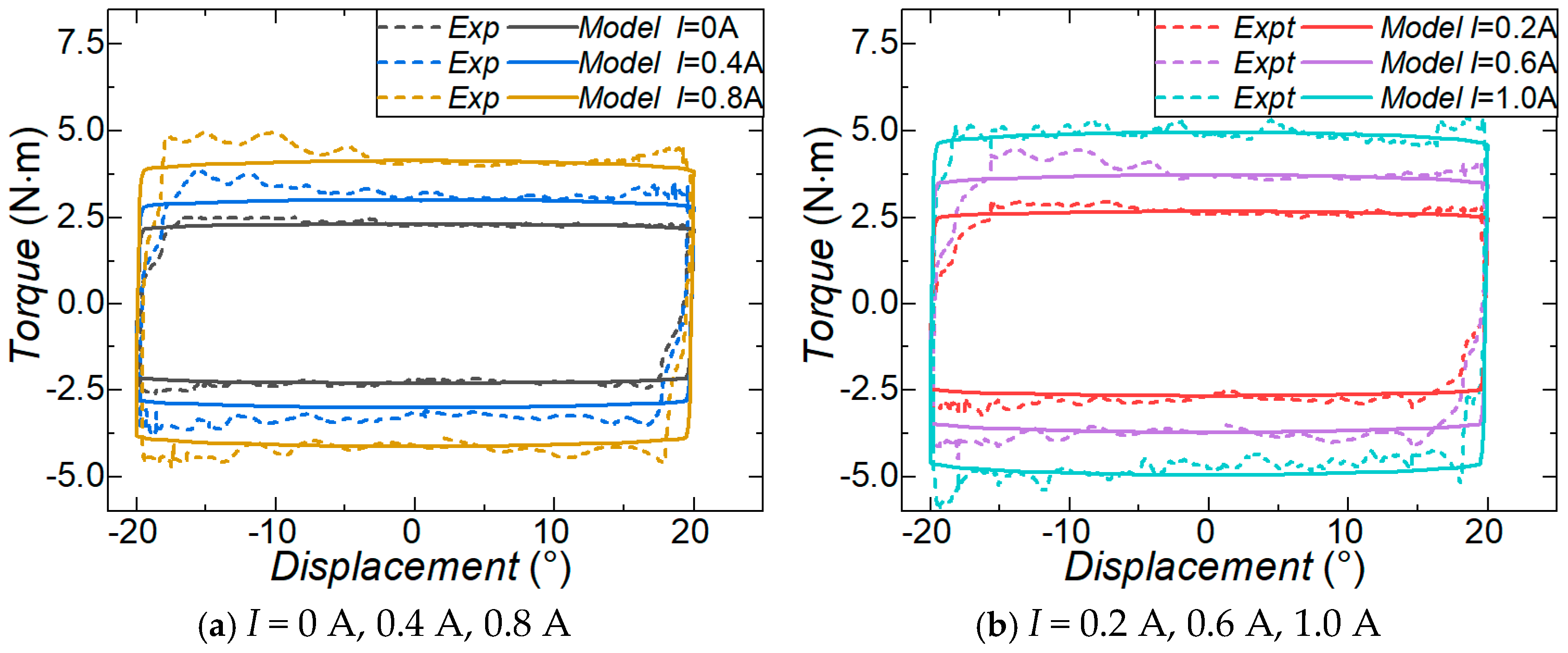
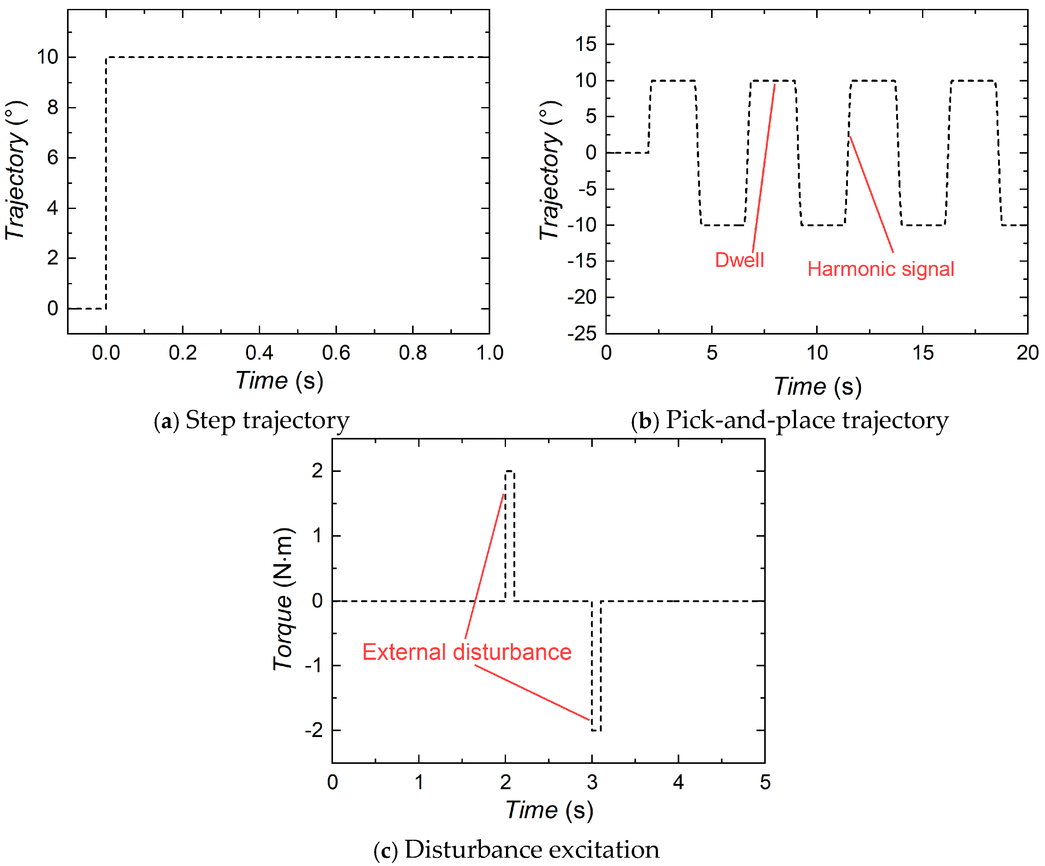
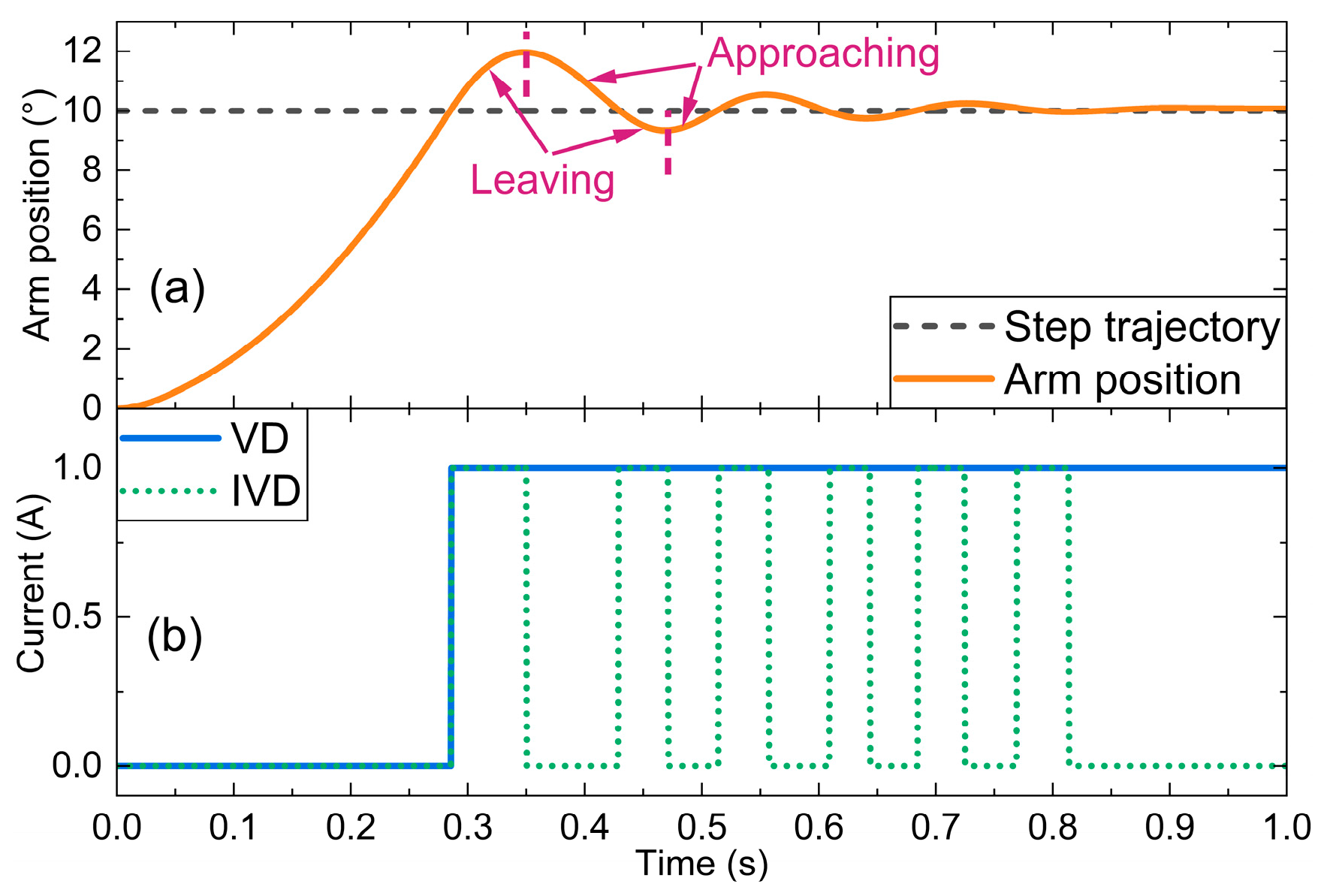
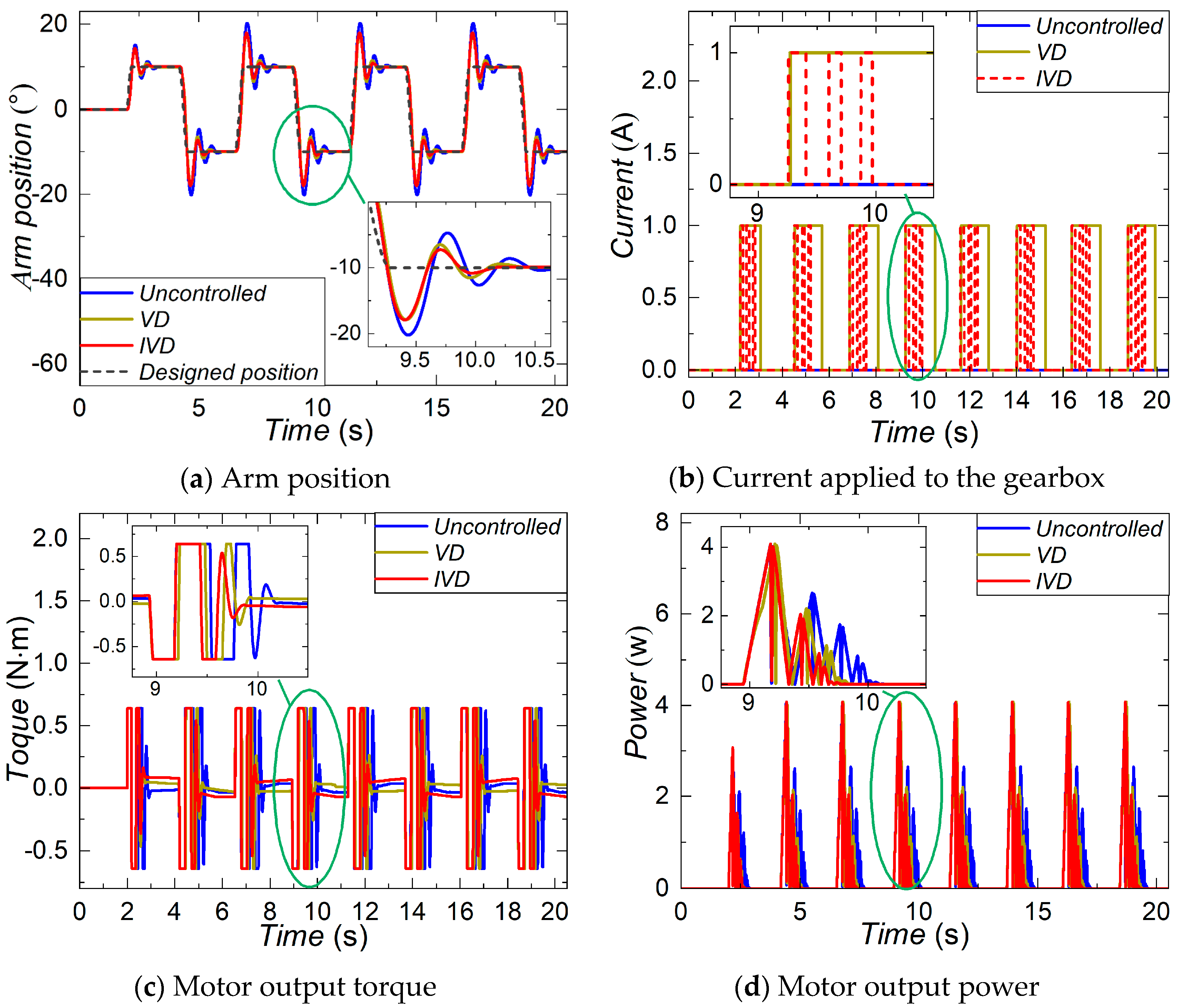
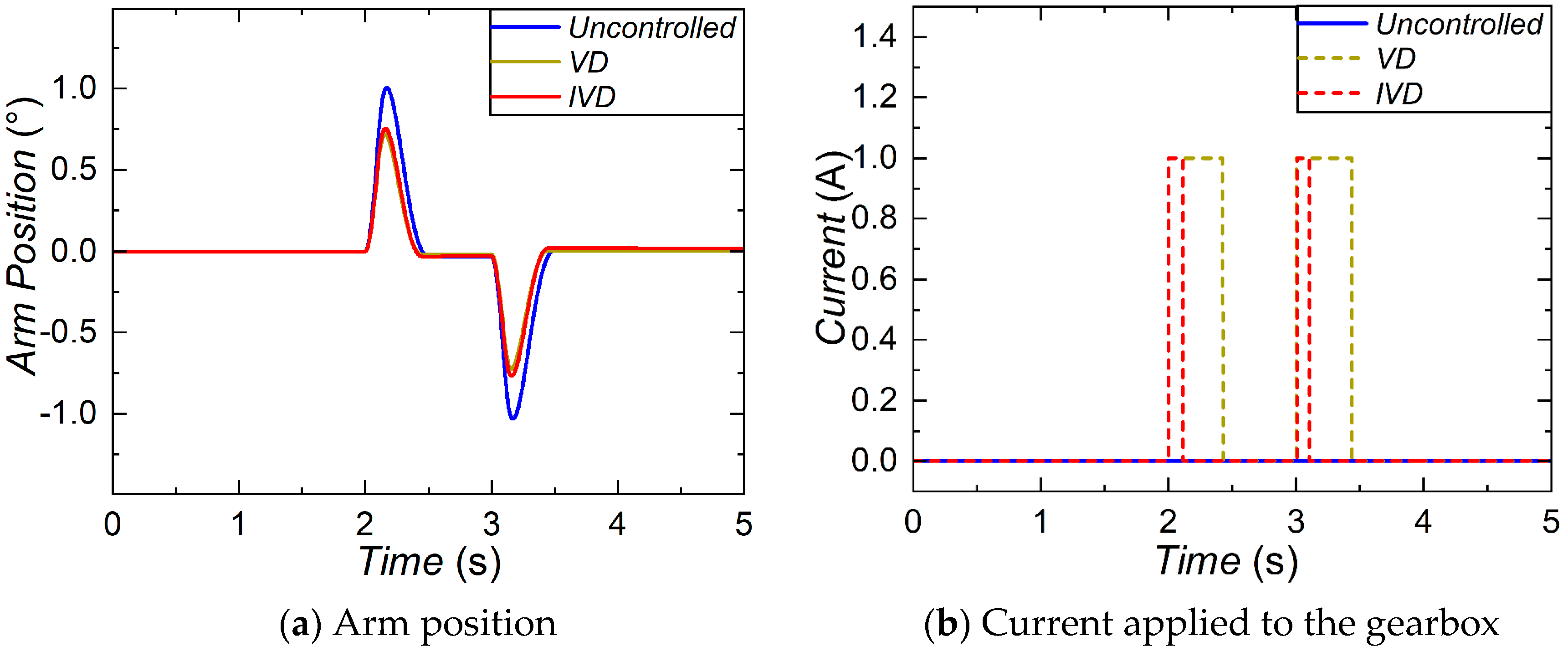
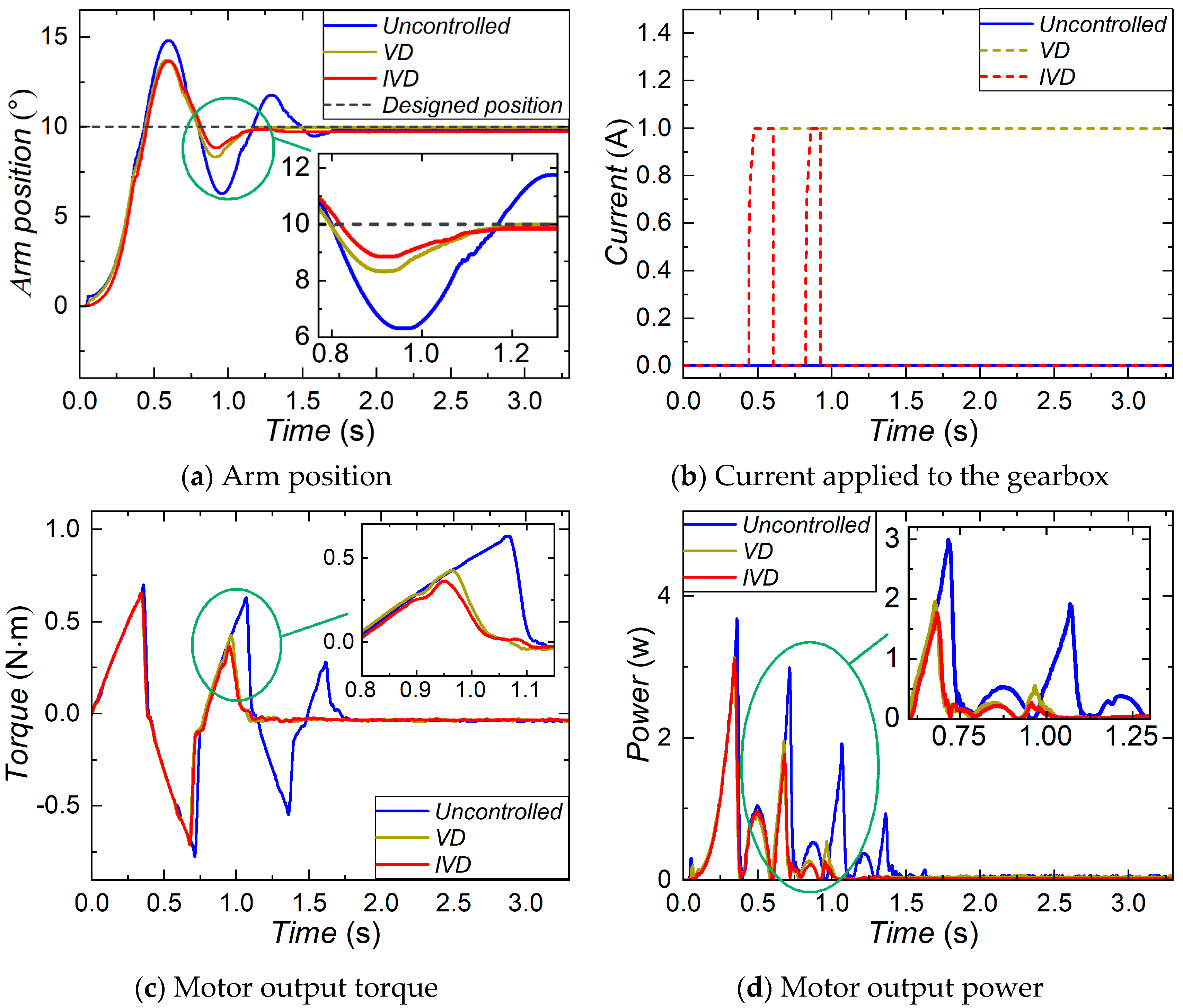
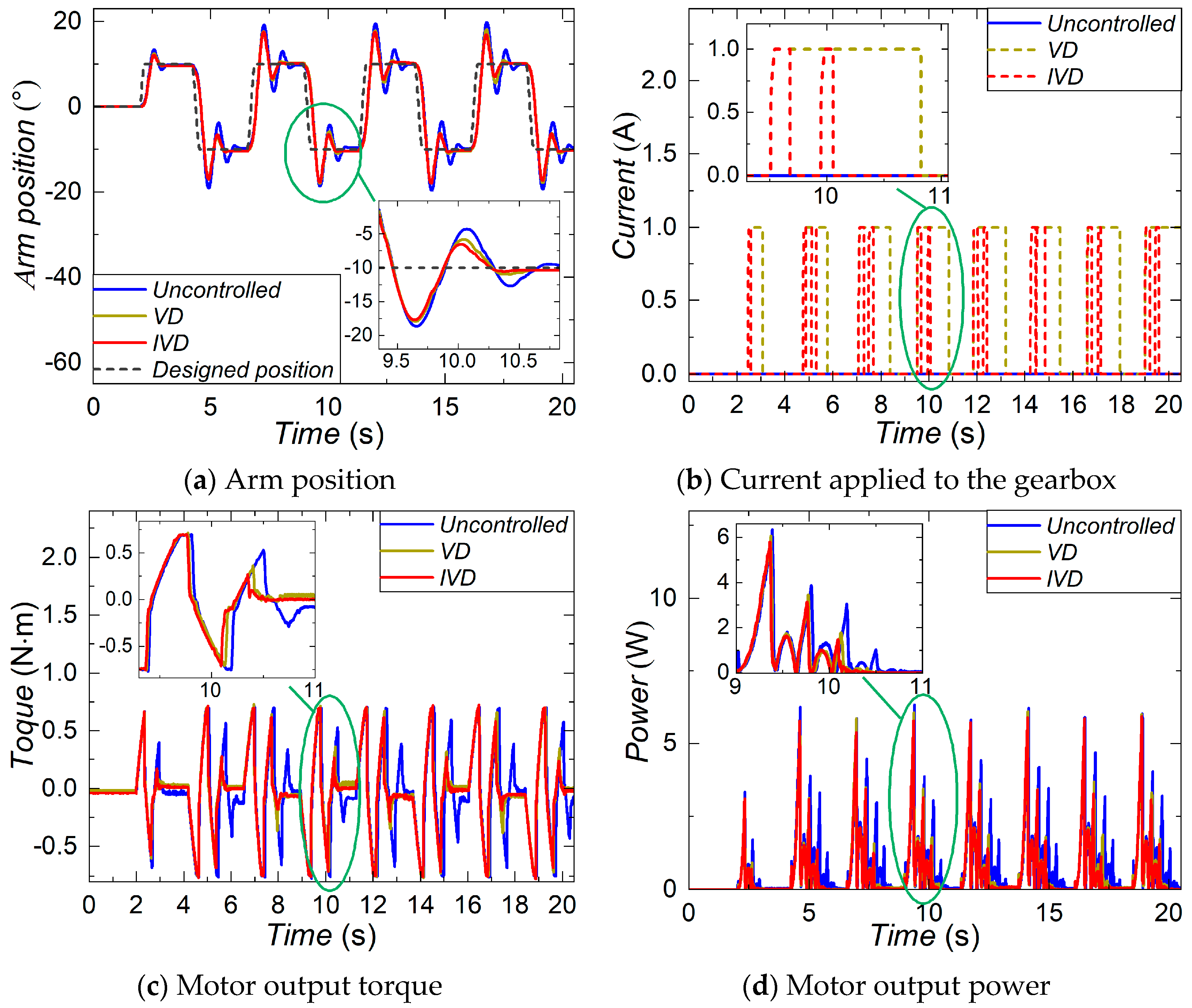
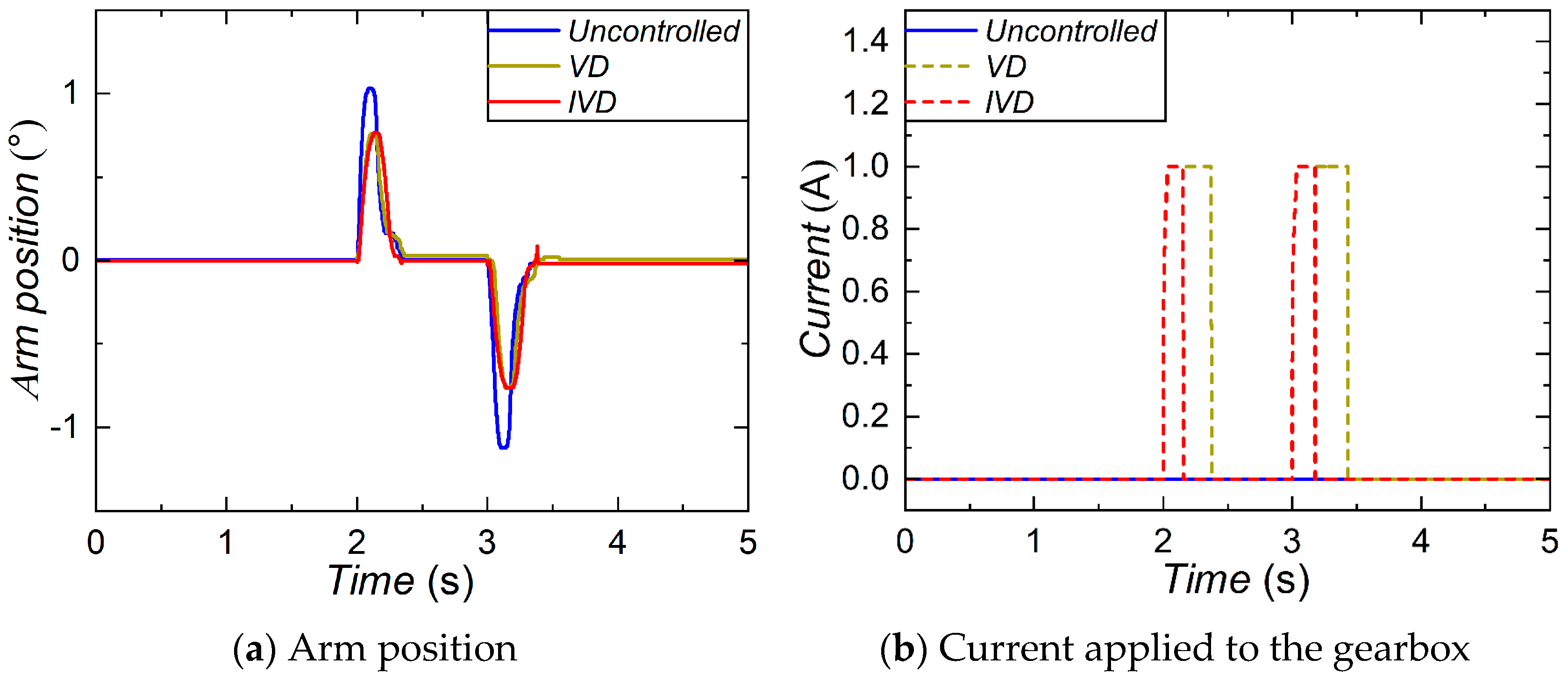
The characterization test revealed that the equivalent damping coefficient of the MR gearbox increases 52.93% from 1.29 to 2.81 N   m   s   rad 1 when the current is raised from 0 to 1 A. The positioning and the anti-disturbance performance of the robotic arm equipped with the MR gearbox were numerically evaluated. In the positioning performance evaluation, the simulation results of the step trajectory reveal that the IVD control can reduce 11.76% overshoot, 14.73% settling time, and save 14.22% energy, compared with the uncontrolled mode. Similar improvements are found in the pick-and-place trajectory. Compared to VD control, the IVD control shows advantages with shorter settling time, less energy consumed by the motor, and reduced energy consumed by the MR gearbox. In terms of anti-disturbance performance, the IVD control can reduce the disturbance quantity by 24.78% compared with the uncontrolled mode, with far less energy consumption by the MR gearbox than the VD control. With the established experimental platform, the positioning and anti-disturbance performances of the robotic arm were tested. The experimental evaluation yielded consistent results to the numerical simulation and further verified that the positioning and anti-disturbance performances of the robotic arm were largely improved by the proposed MR gearbox.
Even though the proposed MR gearbox is effective in the improvement, its limitations should also be considered. The compact design of the MR gearbox increases the manufacturing costs and maintenance. Additionally, an extra power source and control unit are required to achieve the desired improvements in positioning and anti-disturbance performance, which inevitably adds to the complexity of the system. Nevertheless, the proposed method is still a compact solution, as it eliminates the requirement of extra bulky devices to be added to the system, contributing to enhanced performance in positioning control and anti-disturbance.

Author Contributions

Conceptualization, S.S. and J.Y.; methodology, Y.Z., S.S. and G.W.; validation, Y.Z.; formal analysis, L.D.; investigation, Y.Z. and R.Y.; writing—original draft preparation, Y.Z.; writing—review and editing, L.D. and J.Y.; supervision, S.S., L.D., G.W., W.L., X.G., S.Z., H.D. and J.Y.; project administration, S.S.; funding acquisition, S.S. and J.Y. All authors have read and agreed to the published version of the manuscript.

Funding

This research was funded by National Natural Science Foundation of China (Grant No. 52005474, 52105081), USTC start-up funding (KY2090000067), and USTC-IAT-Xiaoxian Intelligent Manufacturing Innovation Center. These financial supports are gratefully acknowledged.

Data Availability Statement

The data that support the findings of this study are available from the corresponding author, upon reasonable request.

Conflicts of Interest

The authors declare no conflict of interest.

References

  1. Billard, A.; Kragic, D. Trends and challenges in robot manipulation. Science 2019, 364, eaat8414. [Google Scholar] [CrossRef] [PubMed]
  2. Moran, M.E. Evolution of robotic arms. J. Robot. Surg. 2007, 1, 103–111. [Google Scholar] [CrossRef] [PubMed]
  3. De Witte, S.; Van Hauwermeiren, T.; Lefebvre, T.; Crevecoeur, G. Learning to Cooperate: A Hierarchical Cooperative Dual Robot Arm Approach for Underactuated Pick-and-Placing. IEEE/ASME Trans. Mechatron. 2022, 27, 1964–1972. [Google Scholar] [CrossRef]
  4. Zhang, L.; Xie, T.; He, S.; Liang, H.; Shi, S.; Shan, X. A simple linear driving actuator for robotic arm used in land-deep sea. Mech. Syst. Signal Process. 2022, 170, 108812. [Google Scholar] [CrossRef]
  5. Xie, Q.; Wang, T.; Zhu, S. Simplified Dynamical Model and Experimental Verification of an Underwater Hydraulic Soft Robotic Arm. Smart Mater. Struct. 2022, 31, 075011. [Google Scholar] [CrossRef]
  6. Cio, Y.-S.L.-K.; Raison, M.; Menard, C.L.; Achiche, S. Proof of concept of an assistive robotic arm control using artificial stereovision and eye-tracking. IEEE Trans. Neural Syst. Rehabil. Eng. 2019, 27, 2344–2352. [Google Scholar] [CrossRef]
  7. Kareemullah, H.; Najumnissa, D.; Shajahan, M.M.; Abhineshjayram, M.; Mohan, V.; Sheerin, S.A. Robotic Arm controlled using IoT application. Comput. Electr. Eng. 2023, 105, 108539. [Google Scholar] [CrossRef]
  8. Jeong, J.-H.; Shim, K.-H.; Kim, D.-J.; Lee, S.-W. Brain-controlled robotic arm system based on multi-directional CNN-BiLSTM network using EEG signals. IEEE Trans. Neural Syst. Rehabil. Eng. 2020, 28, 1226–1238. [Google Scholar] [CrossRef]
  9. Ajwad, S.A.; Iqbal, J.; Ullah, M.I.; Mehmood, A. A systematic review of current and emergent manipulator control approaches. Front. Mech. Eng. 2015, 10, 198–210. [Google Scholar] [CrossRef]
  10. Jin, L.; Li, S.; Yu, J.; He, J. Robot manipulator control using neural networks: A survey. Neurocomputing 2018, 285, 23–34. [Google Scholar] [CrossRef]
  11. Malki, H.A.; Misir, D.; Feigenspan, D.; Chen, G. Fuzzy PID control of a flexible-joint robot arm with uncertainties from time-varying loads. IEEE Trans. Control Syst. Technol. 1997, 5, 371–378. [Google Scholar] [CrossRef]
  12. Nguyen, H.T.; Trinh, V.C.; Le, T.D. An adaptive fast terminal sliding mode controller of exercise-assisted robotic arm for elbow joint rehabilitation featuring pneumatic artificial muscle actuator. Actuators 2020, 9, 118. [Google Scholar] [CrossRef]
  13. Elsisi, M.; Mahmoud, K.; Lehtonen, M.; Darwish, M.M. Effective nonlinear model predictive control scheme tuned by improved NN for robotic manipulators. IEEE Access 2021, 9, 64278–64290. [Google Scholar] [CrossRef]
  14. Elsisi, M.; Mahmoud, K.; Lehtonen, M.; Darwish, M.M. An improved neural network algorithm to efficiently track various trajectories of robot manipulator arms. IEEE Access 2021, 9, 11911–11920. [Google Scholar] [CrossRef]
  15. Islam, R.U.; Iqbal, J.; Manzoor, S.; Khalid, A.; Khan, S. An autonomous image-guided robotic system simulating industrial applications. In Proceedings of the 2012 7th International Conference on system of systems engineering (SoSE), Genova, Italy, 16–19 July 2012; IEEE: Piscataway, NJ, USA; pp. 344–349. [Google Scholar]
  16. Awan, Z.S.; Ali, K.; Iqbal, J.; Mehmood, A. Adaptive backstepping based sensor and actuator fault tolerant control of a manipulator. J. Electr. Eng. Technol. 2019, 14, 2497–2504. [Google Scholar] [CrossRef]
  17. Iqbal, J. Modern control laws for an articulated robotic arm. Eng. Technol. Appl. Sci. Res. 2019, 9, 4057–4061. [Google Scholar] [CrossRef]
  18. Ahamed, R.; Choi, S.-B.; Ferdaus, M.M. A state of art on magneto-rheological materials and their potential applications. J. Intell. Mater. Syst. Struct. 2018, 29, 2051–2095. [Google Scholar] [CrossRef]
  19. Liu, G.; Gao, F.; Wang, D.; Liao, W.-H. Medical applications of magnetorheological fluid: A systematic review. Smart Mater. Struct. 2022, 31, 043002. [Google Scholar] [CrossRef]
  20. Thiagarajan, S.; Koh, A.S. Performance and stability of magnetorheological fluids—A detailed review of the state of the art. Adv. Eng. Mater. 2021, 23, 2001458. [Google Scholar] [CrossRef]
  21. Kang, B.-H.; Kim, B.-G.; Jung, D.; Choi, S.-B. A mathematical model of cavitation behaviour in a single-ended magnetorheological damper: Experimental validation. Smart Mater. Struct. 2022, 31, 035012. [Google Scholar] [CrossRef]
  22. Du, X.; Han, G.; Yu, M.; Peng, Y.; Xu, X.; Fu, J. Fault detection and fault tolerant control of vehicle semi-active suspension system with magneto-rheological damper. Smart Mater. Struct. 2020, 30, 014004. [Google Scholar] [CrossRef]
  23. Deng, L.; Sun, S.; Jin, S.; Li, Z.; Du, H.; Zhang, S.; Li, W. Development of a new magnetorheological impact damper with low velocity sensitivity. Smart Mater. Struct. 2022, 31, 095042. [Google Scholar] [CrossRef]
  24. Ahn, K.K.; Chau, N.H.T. Intelligent phase plane switching control of a pneumatic muscle robot arm with Magneto-Rheological Brake. J. Mech. Sci. Technol. 2007, 21, 1196–1206. [Google Scholar] [CrossRef]
  25. Lima, J.J.; Balthazar, J.M.; Rocha, R.T.; Janzen, F.C.; Bernardini, D.; Litak, G.; Bassinello, D.G.; Tusset, A.M. On positioning and vibration control application to robotic manipulators with a nonideal load carrying. Shock Vib. 2019, 2019, 5408519. [Google Scholar] [CrossRef]
  26. Sapiński, B.; Węgrzynowski, M.; Nabielec, J. Magnetorheological damper–based positioning system with power generation. J. Intell. Mater. Syst. Struct. 2018, 29, 1236–1254. [Google Scholar] [CrossRef]
  27. Ismail, M.; Ikhouane, F.; Rodellar, J. The Hysteresis Bouc-Wen Model, a Survey. Arch. Comput. Methods Eng. 2009, 16, 161–188. [Google Scholar] [CrossRef]
Figure 1. 3D Model of the MR gearbox. (a) full layout; (b) planetary gear set; (c) section view.
Machines 13 00056 g001
Figure 2. Magnetic field simulation.
Machines 13 00056 g002
Figure 3. The schematic of the characterization test.
Machines 13 00056 g003
Figure 4. The characterization test results.
Machines 13 00056 g004
Figure 5. Comparison results of the MR gearbox between the experimental data and the modeled date.
Machines 13 00056 g005
Figure 6. The robotic arm system with the MR gearbox.
Machines 13 00056 g006
Figure 7. Evaluation trajectories and a disturbance excitation.
Machines 13 00056 g007
Figure 8. Comparison of VD and IVD control strategies. (a) arm position; (b) current signal.
Machines 13 00056 g008
Figure 9. Simulation results of the step trajectory.
Machines 13 00056 g009
Figure 10. Simulation results of the pick-and-place trajectory.
Machines 13 00056 g010
Figure 11. Simulation results of the anti-disturbance performance.
Machines 13 00056 g011
Figure 12. Experimental setup of the robotic arm.
Machines 13 00056 g012
Figure 13. Experimental results of the step trajectory.
Machines 13 00056 g013
Figure 14. Experimental results of the pick-and-place trajectory.
Machines 13 00056 g014
Figure 15. The experimental setup of the anti-disturbance test.
Machines 13 00056 g015
Figure 16. The experimental results of the anti-disturbance test.
Machines 13 00056 g016
Table 1. Identified parameters.
CurrentVariable ParametersConstant Parameters
α cA β γ
I = 0 A1000.30155111,188.12
I = 0.2 A101.36720.5294
I = 0.4 A102.18731.0272
I = 0.6 A102.58731.5533
I = 0.8 A103.46721.9453
I = 1 A104.25182.2897
Table 2. The data of the step trajectory simulation.
UncontrolledVDIVD
Overshoot (°)4.5814.0424.042
Reduction proportionNA11.76%11.76%
Settling time (s)0.6630.5950.565
Reduction proportionNA10.25%14.73%
Energy consumed by the motor before t = 0 . 181   s   ( J ) 0.3230.3230.323
Energy consumed by the motor after t = 0 . 181   s   ( J ) 0.3870.3140.286
Energy consumed by the motor in the whole period ( J ) 0.710.6370.609
Reduction proportion (after/whole)NA18.86%/10.28%26.10%/14.22%
Energy consumed by the MR gearbox (J)NA5.2221.655
Table 3. The data of the pick-and-place trajectory simulation.
UncontrolledVDIVD
Average overshot (°)9.5317.0327.032
Reduction proportionNA26.23%26.23%
Average settling time (s)1.5361.2250.997
Reduction proportionNA20.25%35.09%
Energy consumed by the motor (J)11.198.7907.998
Reduction proportionNA21.44%28.53%
Energy consumed by the MR gearbox (J)NA124.27230.775
Table 4. The data of the anti-disturbance simulation.
UncontrolledVDIVD
Disturbance quantity (°)1.0010.7530.753
Reduction proportionNA24.78%24.78%
Energy consumed by the MR gearbox (J)NA102.065
Table 5. The date of the step trajectory test.
UncontrolledVDIVD
overshoot (°)4.7883.6083.608
Reduction proportionNA24.64%24.64%
settling time (s)1.7321.2361.184
Reduction proportionNA28.64%31.64%
Energy consumed by the motor before t = 0 . 440   s   ( J ) 0.3810.3390.333
Energy consumed by the motor after t = 0 . 440   s   ( J ) 0.6020.2910.262
Energy consumed by the motor in the whole period   ( J ) 0.9830.630.595
Reduction proportion (after/whole)NA51.66%/35.91%56.48%/39.47%
Energy consumed by the MR gearbox (J)NA9.932.19
Table 6. The data of the pick-and-place trajectory test.
UncontrolledVDIVD
Average overshot (°)8.5176.996.98
Reduction proportionNA17.93%18.04%
Average settling time (s)2.3181.1751.015
Reduction proportionNA49.30%56.21%
Energy consumed by the motor (J)16.5112.0311.56
Reduction proportionNA27.14%29.98%
Energy consumed by the MR gearbox (J)NA90.2822.13
Table 7. The data of the anti-disturbance test.
UncontrolledVDIVD
Disturbance quantity (°)1.0380.7730.773
Reduction proportionNA25.53%25.53%
Energy consumed by the MR gearbox (J)NA7.8173.071
Disclaimer/Publisher’s Note: The statements, opinions and data contained in all publications are solely those of the individual author(s) and contributor(s) and not of MDPI and/or the editor(s). MDPI and/or the editor(s) disclaim responsibility for any injury to people or property resulting from any ideas, methods, instructions or products referred to in the content.

