Article

The Innovative Design and Performance Testing of a Mobile Robot for the Automated Installation of Spacers on Six-Split Transmission Lines †

by
Jie Pan
1,2,3,*,
Yongfeng Cheng
1,
Chunhua Hu
1,
Ming Jiang
1,
Yong Ma
1,
Fanhao Meng
1 and
Qiang Shi
1
1
State Grid Electric Power Engineering Research Institute Co., Ltd., Beijing 100069, China
2
China Electric Power Research Institute, Beijing 100055, China
3
School of Mechanical Engineering and Automation, Beihang University, Beijing 100191, China
*
Author to whom correspondence should be addressed.
This is an extended version of our paper published in Pan, J., Hu, C., Jiang, M., Ma, Y., Meng, F., He, X., Liu, C. Development of a Spacer Bar Installing Robot for Six-Split Transmission Lines. In Proceedings of the 8th International Conference on Computing, Control and Industrial Engineering (CCIE2024), Singapore, 2024; pp. 11–17.
Machines 2025, 13(5), 432; https://doi.org/10.3390/machines13050432
Submission received: 17 March 2025 / Revised: 25 April 2025 / Accepted: 9 May 2025 / Published: 19 May 2025
(This article belongs to the Special Issue Recent Developments in Machine Design, Automation and Robotics)

Abstract

The spacer is an important component of a transmission line and can effectively prevent wires from whipping each other and inhibit vibration. Given the complex installation conditions of multi-split lines, the installation of spacers is mainly achieved through manual work, which has the disadvantage of heavy labor intensity and a high risk factor. The robots that install two-split and four-split spacer bars cannot be applied to the complex operating conditions of six-split transmission lines. In order to improve the installation efficiency of spacers and reduce operating costs and risks, a new type of spacer-installing robot was researched based on the six-split transmission lines in this paper. Through the theoretical analysis of the wire’s arc sag, the moving device of the robot was designed. In order to improve the operating efficiency of the robot, the storage and feeding device of the six spacers was designed. A planar arm with the ability to assemble the spacer was designed. The overall design of the robot was completed by integrating the design of each unit. Through the experimental test, the results indicated that the robot was capable of installing six spacers at once, the maximum moving slope was 15 degrees, and the error rate in the spacer installation was 2.33%, which matched the manual installation of the spacers. The robot provided new ideas for the design of new transmission line engineering equipment and expanded the scope of the application of robots in the power industry.

1. Introduction

Most high-voltage transmission lines are located in the field, which is frequently affected by the wind and snow, so it is a very important task to ensure the safety and stable operation of these transmission lines. The spacer is an important component of a transmission line and can effectively prevent wires from whipping each other, inhibit breeze vibration, and sub-file distance oscillation [1,2]. At present, the installation of spacers on high-voltage transmission lines mainly relies on workers carrying spacers to walk on overhead wires to achieve their installation, which poses high risks and inefficiency. Nevertheless, significant progress has been made in the study of high-voltage transmission line inspection robots [3,4], such as using the Unmanned Aerial Vehicle (UAV) for the inspection of transmission lines [5,6], using wheeled robots in wire inspection [7], etc. This equipment can be adopted to replace the manual labor of workers to achieve automated routing inspection, but research into multi-split spacer-installing robots is still relatively limited [8,9,10,11]. At present, this field still relies on workers moving carefully on wires (as shown in Figure 1) to achieve spacer installation and even using helicopters to support workers in their installation of spacers, which requires more workers and equipment in the process. In the actual spacer installation, workers have to climb a transmission tower to the overhead wire position and then take a few spacers while moving slowly on the wires; this process is laborious and dangerous. When the workers reach the installation location, they can use their tools to install the spacers. It should be noted that the greater the number of transmission line splits, the more difficult the installation is. Currently, the spacer installation method has high risks, inefficiencies, and other shortcomings. In addition, workers are affected by high winds, rain, and snow during their work, which creates challenges to power construction. The current research and development of transmission line robots is focused on transmission line inspection [12,13,14,15,16]; it is still difficult for these robots to automatically install multi-split spacers.
With the application of robotics in the field of the power industry increasing, there have been two-split spacer- [17] and four-split spacer-installing robot [18] research reports. However, with the increase in the amount of wire splitting, spacer assembly difficulty has also increased [19,20,21,22,23]. For robots on two-split and four-split wires, the design for moving and installing devices is simpler, in addition to their reduced weight and size, leading to a more straightforward mechanical and control system design. This is due to the reduced number of wire splits, which facilitates easier adjustment in the wire spacing. But six-split lines have more spacer chucks and non-uniform spacing between wires, making the development of spacer-installing robots more challenging [24,25,26,27,28]. The high-voltage transmission lines are approximately 300 m~500 m in length, while the existing four-legged and climbing robots are difficult to adapt to the long-distance environment of the wires [29,30,31]. Meanwhile, UAVs are not yet able to automatically install multi-split spacers and can only achieve transport and inspection functions. As the demand for electrical energy increases, the scale of electrical construction will continue to expand; it is an important and difficult task to install spacers. Thus, there is an urgent need to develop a new type of construction equipment to improve the installation of spacers. This new equipment is needed to grant the ability to move accurately and to efficiently install spacers on the wires.
Based on the above analysis, there is a new spacer-installing robot for the six-split transmission lines, designed in this paper. This paper is focused on analyzing the effect of robot weight on the shape of the wire, the effect of the surface geometry of the wheels on the ability to move, the analysis of the motor control logic inside the robot, and the performance test of moving and installing spacer bars on real six-split transmission lines. The structure of this paper is divided into seven parts. The first part is the background and significance of the study, the second part is about the relevant research content of this study, the third part is the theoretical modeling and analysis process, the fourth part is the mechanism design method and process of the robot, the fifth part is the overall design of the robot, the sixth part is the test and discussion, and the seventh part is the conclusion and outlook.

2. Related Research

Previous robot designs primarily focused on achieving movement along transmission lines, with limited research dedicated to operational functionality. This is because the robot must perform both movement and operational functionality on the six-split transmission lines, which requires stringent demands on its mechanism design, motion control, and workflow design. For instance, the robot’s movement along the wire will cause deformation of the wire; thus, the theoretical analyses need to be made on the effect of gravity during movement. The encoder is a common position sensor for robots, but the spacer-installing robot requires precise positioning, so additional positioning sensors need to be added to the robot. Based on the need for mechanized construction, we have studied a six-split spacer installation robot, which was capable of slowly installing spacers under remote control [32]. However, critical aspects including design theory validation, mobility characterization, and automated installation performance evaluation remained uninvestigated. The actual capability of the robot was very limited, and it is not yet possible to apply it in real engineering.
It is worth noting that the robot needs to overcome the influence of the slope of the wire while moving, so it needs an in-depth theoretical study of the impact of the robot on the wire. Secondly, the mobility of the robot must be a prerequisite to ensure the operation, and further research on the mechanism design and motion control is needed. Finally, the performance test of the robot in practical engineering is an important aspect of presenting the real ability of the robot. Based on the above analysis, it is necessary to deepen further the theoretical modeling and mechanism design research work based on the previous research.

3. Modeling

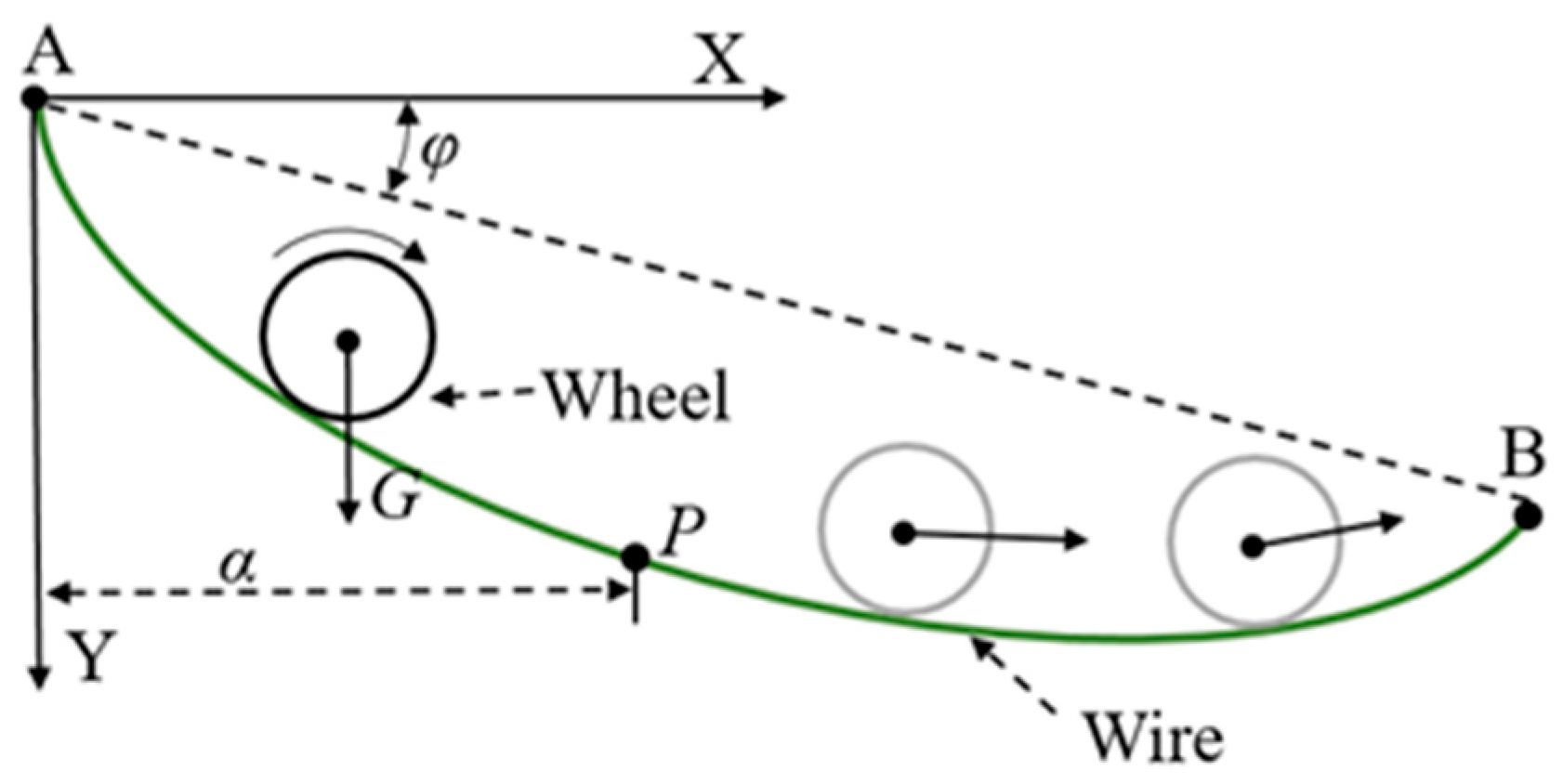
3.1. The Impact of the Robot on the Wire

Due to the long distance of the transmission line and the complex moving environment, the robot made by the simple mechanical structure form is not qualified. The wheeled robot is capable of good mobility on the wire; therefore, the design of the mobile form of the robot will be wheeled. When the robot is moving on the wire, the wire is affected by the weight of the robot, which leads to a change in the radius of the wire, as shown in Figure 2. Therefore, it is necessary to make a theoretical analysis of the slope in the robot’s moving direction on the wire.
The shape of the suspension wire of steel-core aluminum stranded wire can be obtained from the equation of the suspension wire. Although the wire has a certain degree of stiffness, with the file distance spanning larger factors, the impact of gravity on the shape of the wire is much greater than the impact of stiffness, so the impact of stiffness on the shape of the wire can be ignored.
For the equal density wire, defining point A as the coordinate origin, according to the catenary equation [33], the value of the vertical coordinate y at point P is:
y = H ω c h l ω 2 H c h l 2 x ω 2 H
The x is the horizontal coordinate at point P, and the ch is the hyperbolic cosine function. The l is the length of the wire, H is the horizontal tension in the wire, and ω is the self-gravity force in unit length of the wire. σ = H/s, g = ω/s, σ is the horizontal stress of the line; g is the ratio of gravity to the load of the line, and s is the cross-sectional area of the wire.
Therefore, Equation (1) can be expressed as:
y = σ g c h l g 2 σ c h l 2 x g 2 σ
When there is a concentrated load on the wire, the value of the longitudinal coordinates of any point on the wire can be calculated as:
y = l ω 2 H cos φ + l a l Q H ± h l x ω 2 H cos φ x 2
Q is the gravity of the concentrated load. φ is the height difference angle of the wire at the suspension points at both ends. a is the horizontal distance from point P to point A. When the concentrated load is located in the middle of the line, the arc sag value ymax reaches its maximum and can be expressed in the following form:
y max = l 2 8 H ω cos φ + 2 Q l
At this point, the value of moving angle θ reaches its maximum and satisfies the equation relationship:
l 2 tan θ = y max
The maximum moving angle θmax can be obtained by calculating Equations (4) and (5):
θ max = arctan l 4 H ω cos φ + 2 Q l
If the ends of the wire are equal, the value of φ is 0.
θ max = arctan l 4 H ω + 2 Q l
From Equation (7), it can be calculated that the maximum moving angle θmax of the robot on the wire is mainly related to l, H, Q, and ω; the θmax is inversely proportional to the value of H. Since the length of the wire l and ω are constant values after the wire has been built, the increasing weight of the robot will lead to a larger moving slope. Furthermore, the value of l is not consistent due to the terrain, but the larger the value of l, the larger the value of θmax. Among the many factors, only Q can be adjusted by mechanical design. Based on this, a lightweight mechanism should be considered for the robot to enhance its moving performance.

3.2. Forward Analysis of Robot

The moving mechanism of the robot is composed of active and follower wheels, and the wheels are driven by DC motors. As shown in Figure 3, the driving torques of the traveling wheels are set to be M1 and M2, the positive pressures generated by the wire on the wheels are N1 and N2, the friction generated by the two wheels on the wire are F1 and F2, the weight of the robot is mg, and the rate of moving on the wire is v.
Along the direction of gravity is the following equation:
N 1 + N 2 m g cos θ = 0
Along the direction parallel to the wire is the following equation:
F 1 + F 2 m g sin θ = 0
θ represents the angle of the wire relative to the horizontal ground.
The moment balance equation is established based on the center of the wheel as follows:
M 1 M f 1 F 1 r = 0
M 2 M f 2 F 2 r = 0
F i = μ Ν i
M f i = N i δ
The values of i are 1 to 2, r is the radius of the driving wheel, μ is the coefficient of rolling friction between the wheel and the wire, and δ is the coefficient of rolling resistance between the wheel and the wire.
Since both wheels are made of the same material, the coefficient of rolling friction and the coefficient of rolling resistance between the wheels and the wire are the same. Associating Equations (8)–(13), the following can be calculated:
M 1 + M 2 = r m g sin θ μ N 1 + N 2 = m g sin θ
From Equation (14), the main factors affecting the movement of the robot on the wire are the friction coefficient μ, the rolling resistance coefficient δ, and the robot weight mg. To improve the moving ability of the robot, the friction between the robot wheels and the wire should be increased. Therefore, the moving ability of the robot is increased by adding a pressing wheel to the driving wheel of the robot, which increases the positive pressure of the wire on the driving wheel and thus increases the moving ability of the robot.
As shown in Figure 4, the positive pressures generated by the wire on the pressing wheels are N3 and N4. The F3 and F4 are the rolling friction forces generated by the wire on the surface of the pressing wheel, which drive the rotation of the pressing wheel. The values of F3 and F4 are controlled by the rolling resistance screw adjusting the distance between the active and pressing wheels.
With added pressing wheels, the force analysis in the direction of gravity is:
N 1 + N 2 N 3 N 4 m g cos θ = 0
With the addition of compression sheave, the force analysis in the direction of the parallel wire is:
F 1 + F 2 F 3 F 4 m g sin θ = 0
Ni (i = 1~4) is the positive pressure from the wire applied to the four wheels; Fi (i = 1~4) is the friction force from the wire applied to the four wheels and Fi =μNi; θ is the angle between the wire and the horizontal ground; and m is the weight of the robot.
Thus, the condition for stable motion of the robot on the wire is:
F 1 + F 2 m g sin θ + F 3 + F 4
It can be calculated by bringing Equation (12) into Equation (17):
μ N 1 + N 2 m g sin θ + F 3 + F 4
From Equation (18), it can be seen that the positive pressure of the robot during its movement is not only related to the weight of the robot but also to the pressure exerted by the pressing wheels on the wire during the movement. Considering the possibility that the robot on the wire may slip in movement, it is necessary to design mechanism devices for the robot that can actively adjust the rolling friction generated by the active wheels on the wire; thus, the movement of the robot can be controlled by adjusting the force generated by the pressing wheels.

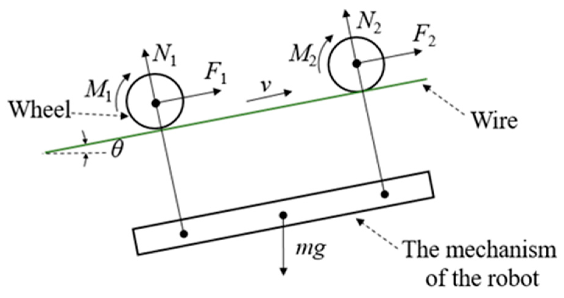
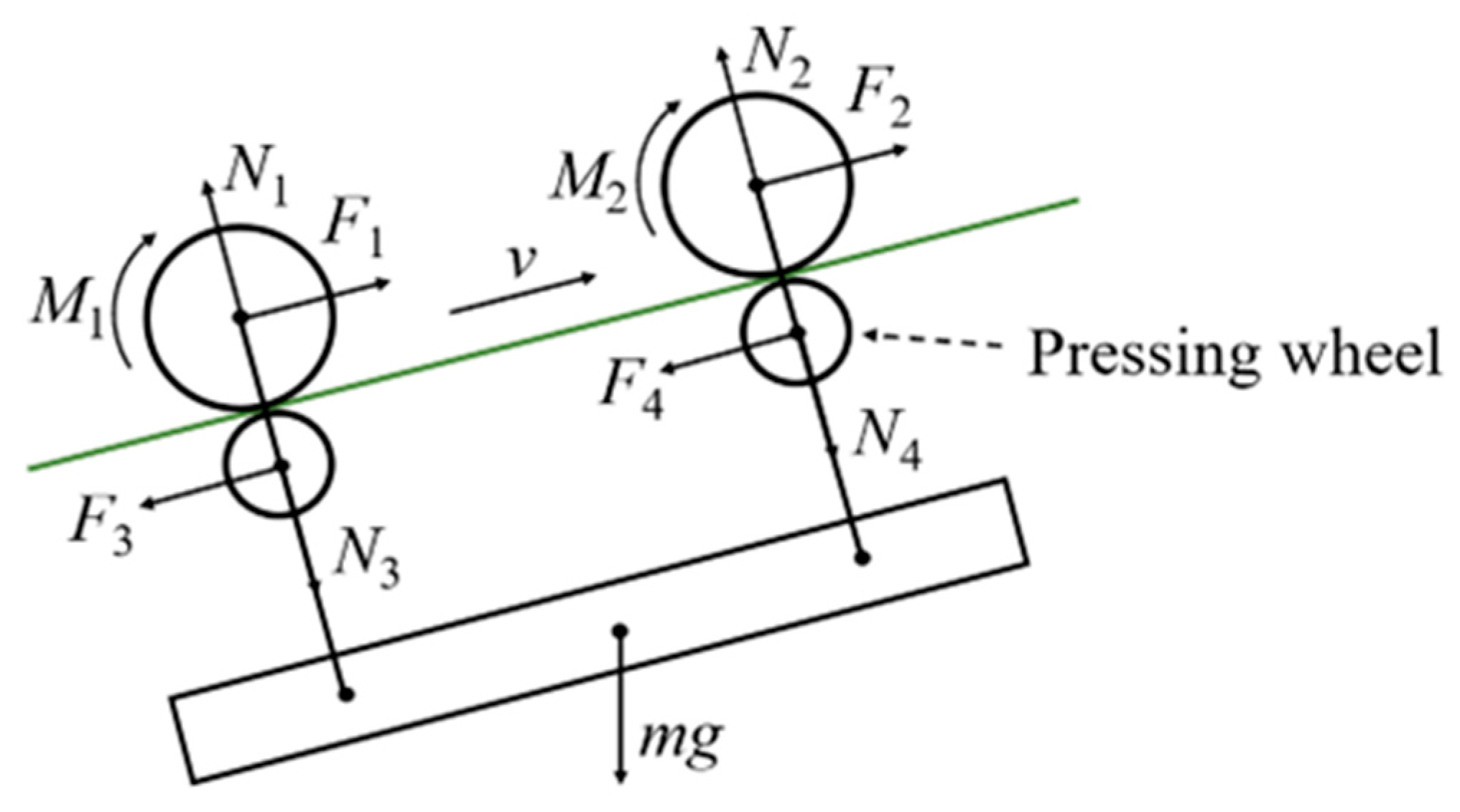
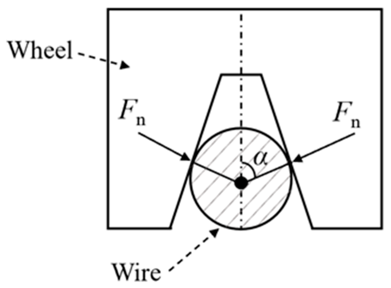
3.3. Wheel Cross-Section Analysis

Wheels are the important components for the robot to achieve mobility on the wires, and the design of the wheels has a significant impact on the mobility of the robot. Since the transmission line is located in the sky, the wheel is designed as a groove structure to increase the safety of the robot. The cross-sectional shape of the wheel is analyzed below. The cross-sectional shape of the wheel can be mainly classified as trapezoidal and curved, as shown in Figure 5 and Figure 6. The friction generated by the two forms of wheels as they move on the wire is analyzed as below.
Assuming that the wheel and wire are not deformed, the force relationship between the wheel and the wire is:
2 F n cos α 1 = W 1
Fn is the pressure of the wheel on the surface of the wire and W1 is the vertical downward force of Fn.
F f 1 = 2 μ F n
μ is the coefficient of static friction of the wheel surface on the wire. Ff 1 is the static friction.
Solving Equations (19) and (20), the following can be calculated:
F f 1 = W 1 μ cos α 1
When the wheel is of a curved section, the contact type between the wheel and wire is the line contact. The positive pressure on the line should be calculated by using the mathematical integral.
2 0 α 2 F n 2 cos α d α = W 2
Fn2 is the pressure of the wheel on the surface of the wire, and W2 is the vertical downward force of Fn2.
2 F n 2 sin α 2 = W 2
F n 2 = W 2 2 sin α 2
F f 2 = 2 0 α 2 F n 2 μ d α
Calculating Equations (24) and (25), the following can be obtained:
F f 2 = α 2 sin α 2 W 2 μ
As the driving wheel load is the same, the following exists:
W 1 = W 2
Calculating formulas (21), (26), and (27), the ratio k of the two friction forces is obtained as:
k = F f 1 F f 2 = sin α 2 α 2 cos α 1
If the boundary contact point of the wheel forms the same angle as the center of the wire circle, the following exists:
α 1 = α 2
Therefore, Equation (28) can be expressed as:
k = tan α α
Therefore, under the condition that the weight of the robot and the material of the wheel are the same, the ratio of the driving force provided by the two types of driving wheels with trapezoidal and curved interfaces is determined by the contact angle α. Since tan α > α, k > 1, and it can be concluded that the driving force provided by the driving wheel with a trapezoidal cross-section is greater than that of the driving wheel with an arc interface.

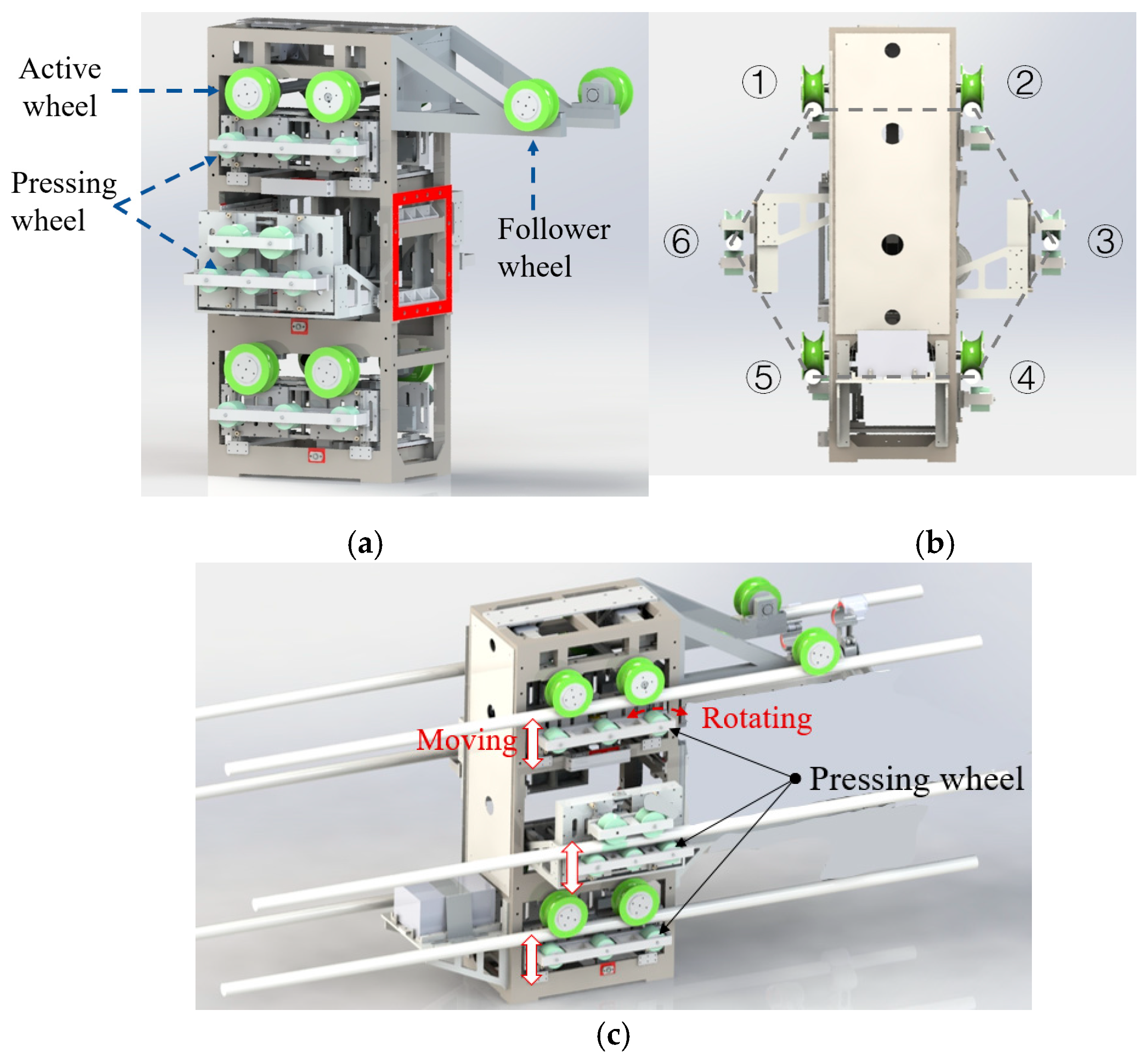
4. Mechanical Design

4.1. Subsection

Based on the analyses in Section 3.3, the forward wheel of the robot is designed as having a trapezoidal cross-section, and a pressing wheel is designed under the forward wheel to change the friction value between the forward wheels and the surface of the wires. By controlling the friction between the wheels separately, the forward and turning movements of the robot are controlled. Since the spacers are standard hexagonal shapes with fixed spacing values, the spacing of the six wires needs to be arranged into hexagonal shapes before installing the spacers, as shown in Figure 7.
Based on the above analysis, the spacing of the six wheels in the robot’s moving mechanism is designed as a hexagonal shape (The wheel numbers are ①~⑥), which in turn ensures that the spacing of the wires matches the spacing of the ends of the spacers, as shown in Figure 8a,b. The pressing wheels are used to adjust the rolling friction of the active wheel on the wire, thus achieving speed adjustment of the robot, as shown in Figure 8c. The center of mass of the robot will change during the moving process on the wire, and a large offset of the center of mass will cause the robot to be unstable. Therefore, it is necessary to design follower wheels for the robot around the active wheel to improve the stability of the robot. When the center of gravity of the robot is designed between the active wheel and the follower wheel, the rotational torque generated on the wheels can effectively counterbalance each other, and thus the robot has a more stable movement ability on the wire than on the unfollowed wheels.

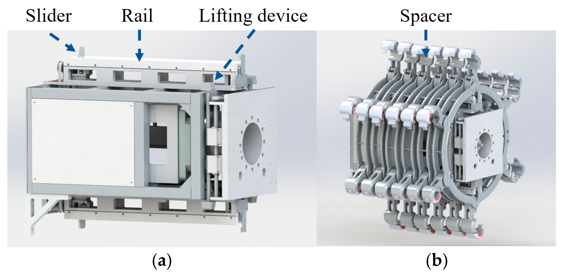
4.2. Transfer Mechanism for Spacer

Besides the mobility function, the robot should also have the ability to store and transfer spacers to increase installation efficiency. Therefore, once the robot arrives at the target location on the wire, the internal transfer mechanism can transfer the spacers from the storage location to the aim location that can be lifted and installed. Considering that two spacers were installed at a spacing of about 60 m in length and the distance between two towers was 300 m~500 m in length, the storage mechanism was designed to be capable of storing six spacers. The storage and transfer mechanisms of the spacers were designed inside the robot, as shown in Figure 9. Firstly, the design of the spacer storage mechanism, which is composed of the upper and lower rails, can accommodate a maximum of six six-split spacers. In the design of the transfer mechanism, the spacer is transferred on the rail by controlling the ball screw, and there is a displacement sensor at the end of the rail, which can measure the transfer status of the spacer in real time. When the spacers are transferred to the end of the guide rail, the lifting device in the transfer mechanism will send the spacers to the pre-installed position on the upper part of the guide rail. The motion speed of the transfer mechanism is 30 mm/s. To prevent jamming or misalignment, the spacer is mounted on the upper and lower sliders of the transferring mechanism and is synchronously moved by the upper and lower guide rails to achieve precise transport.

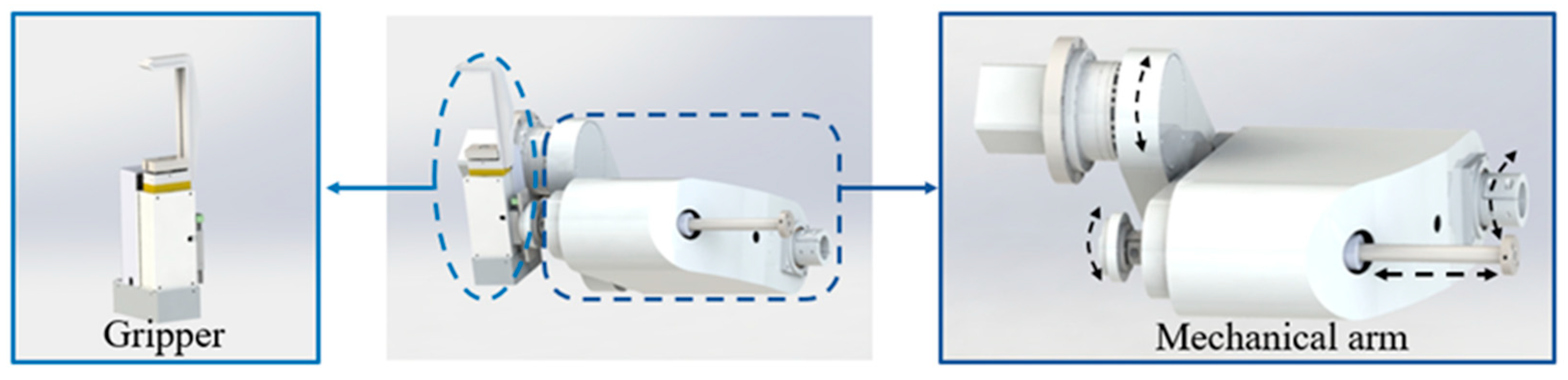
4.3. Installation Mechanism

The main task of the robot is to mount the spacer, so it is necessary to research the installation characteristics of the spacer. Currently, the installation of spacers on the wire can be divided into two ways: one is through the bolt constraint, the other is through the snap constraint. The first requires workers to repeatedly rotate the tool to achieve the installation, and the process is more complicated. The latter requires workers to press hard to achieve installation, and the process is relatively simple. As the robot is driven by motors, the second type of installation method is more compatible with the robot.
The installation of the spacer involves two parts: one is to contact the six spacer chucks with the six wires to complete the wires, and the other is to clamp the spacer chucks, so it is necessary to design a lifting mechanism and the installation mechanism for the spacer. The lifting mechanism of the robot mainly consists of a 3-degree-of-freedom planar mechanical arm, controlling the rotation of the arm to move the spacer from the top of the guide rail to the designated position, and then completing the spacer chuck on the wire. To install the spacer easily, the spacer chuck is of a snap type (Figure 10), clamping the chuck of the spacer to complete its assembly. The specific process is that the chuck drives the latch to rotate under the action of force F, and under the drive of the spring on one side of the latch, the latch can lock the chuck. The clamping mechanism of the spacer is mainly made of a 1-degree-of-freedom C-shaped gripper (Figure 11), the gripper on the head of the spacer is controlled to achieve the installation of the spacer.

4.4. Control System

Besides the sensing signals, the most frequent communication signals between the controller and the base station are motion control signals. In the various mechanisms of the robot, all mechanism movements are driven by stepper motors. Therefore, precise control of the motion mechanism can be achieved by the precise driving of the motors by the robot. Since the robot is required to perform a variety of functions, the motors are controlled in a closed loop rather than an open loop, which can protect the lifetime of the motors and the transmission lines. The closed-loop control of existing motors is mainly achieved by encoder and current feedback signals. The encoder is used to provide feedback on speed and position information, while the current value is used to provide feedback on torque to prevent motor jamming. Except for the encoder, a Real Time Kinematic (RTK) was installed inside the robot to enhance its movement accuracy. The calculation of the robot’s spatial position on wires is based on the fusion of the encoder and RTK information.
The primary motion control of the robot is the control of the motors, which contain the forward wheel drive motors and the gripper drive motor. Motor control involves coupled control of both displacement and output force, thus achieving force–position coupling. The displacement is controlled by the encoder feedback data to control the motion displacement of the robot and the output displacement of the gripper. The force control is by the current feedback data from the motor to control the output torque of the motor. The entire control system of the motor is shown in Figure 12.

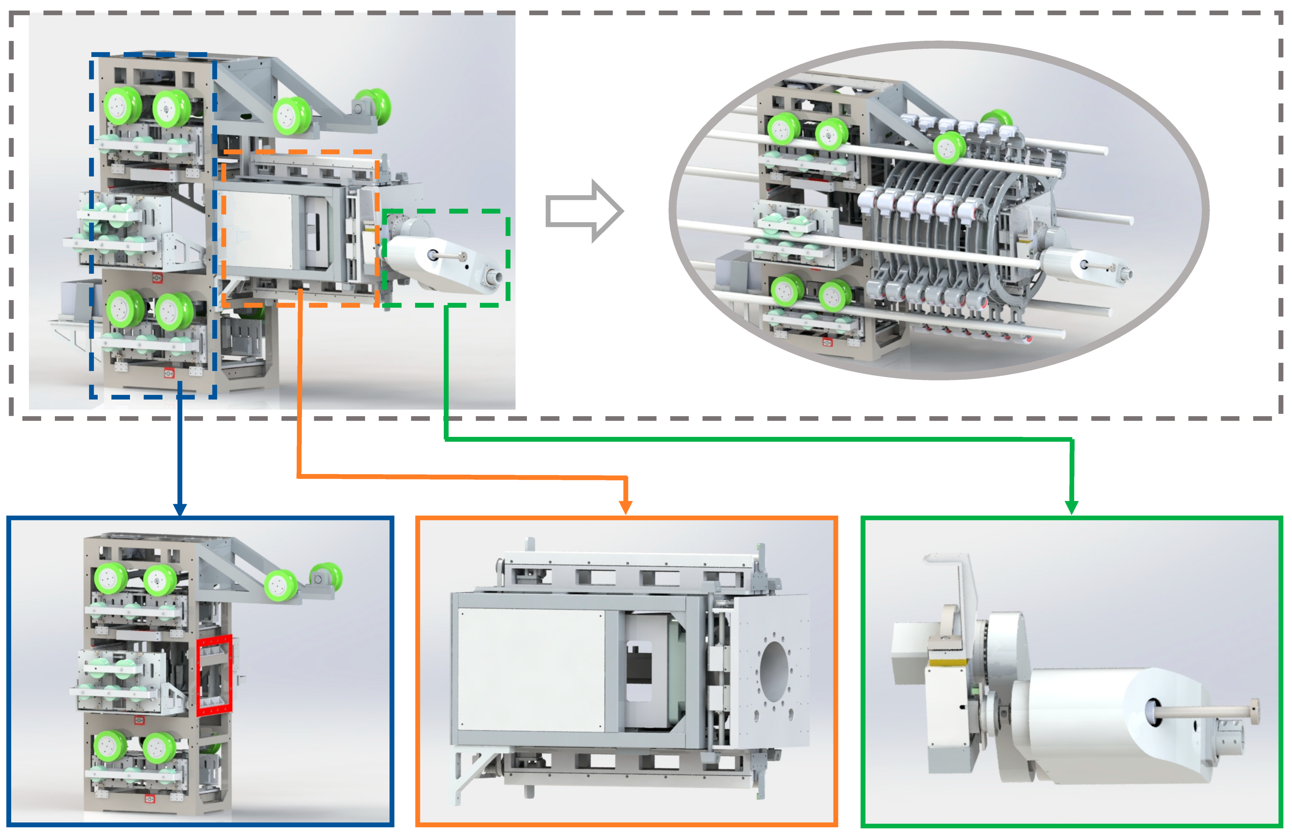
5. Integration and Assembly

5.1. Integrated Design

Based on the above study of the robot’s mechanism, each component was fabricated individually, and the prototype was assembled according to the 3D model. During the integrated design process, factors such as force distribution and operational workspace were carefully considered to prevent motion interference. In addition, since the robot is to be lifted onto the wire, the top of the robot should be designed to allow it to be lifted. Within the limits of structural rigidity, the parts of the robot should be small and lightweight. The parts should be bolted together to ensure the overall structural stability of the robot.
The robot contains the moving mechanism, spacer storage and transfer mechanism, and installation mechanism. In terms of the control system, the robot contains the motion control of the moving mechanism, the spacer transfer control, and the spacer assembly control. Combined with the component structure diagram of the robot and the existing machining process, the robot mechanism can be completed by machining and prototype assembly, as shown in Figure 13. The moving mechanism is mainly used to drive the robot to move and stop, and another role is to form the six split lines into regular hexagons to facilitate the installation of spacers. The storage and transfer mechanism was located inside the robot for the storage of six spacers and the transferring capability. The installation mechanism was designed at one end of the transfer mechanism and was driven by a flat mechanical arm to assemble the spacers.

5.2. Prototype Assembly

Based on the analyses made in the previous section, parts are machined separately for each part of the robot’s mechanism, which used 3D printing, wire cutting, and machine tool machining. High-strength 304 stainless steel material was used for the main frame of the robot to ensure its structural rigidity. Based on the previous 3D drawings of each part of the robot for component assembly, the robot prototype and the composition of each part are shown in Figure 14. The robot contains a communication module, human–machine interaction, power supply module, advancement mechanism, storage and transfer mechanism, spacers, upper wire mechanism, spacer mounting mechanism, and so on. The robot prototype follows the relationship of each module specified in Section 4.1 during assembly.

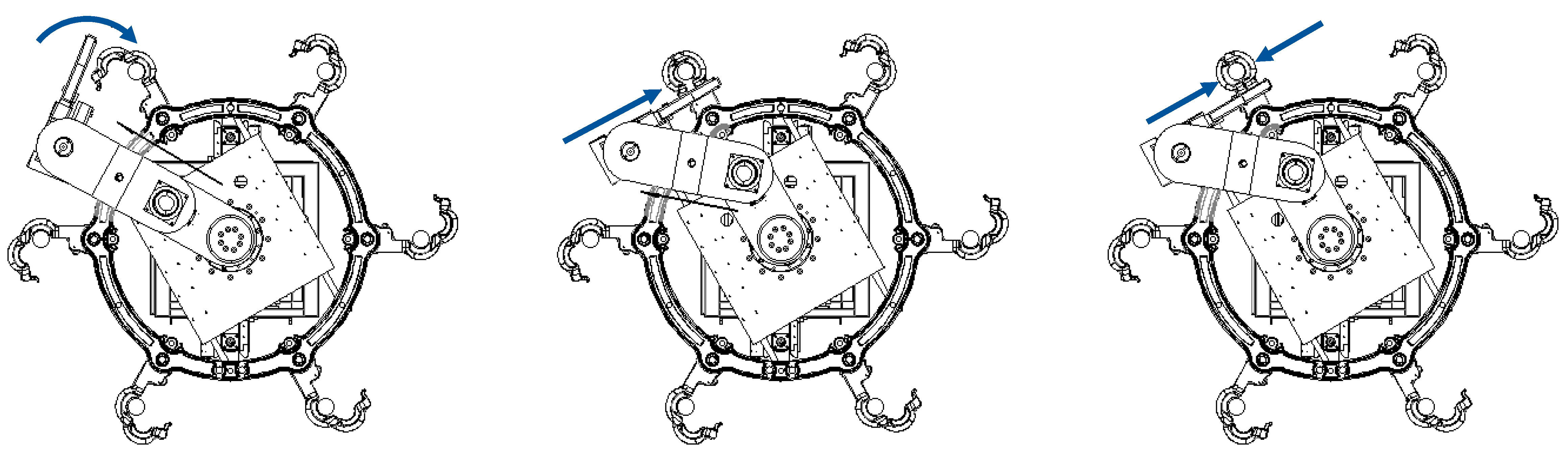
5.3. Spacer Installation Process Design

In the process of installing spacers, workers can make micro-adjustments to the installation position according to actual needs. Unlike installation by workers, the installation of spacers by robots is performed strictly in accordance with the installation procedure, so it is necessary to design a correct installation procedure for the robots. During the installation of the spacer, workers would first wrap the chuck of the spacer around the surface of the wire and then use the installation tools to complete assembly. Therefore, the design of the installation mechanism for the robot can be based on the installation process of workers.
The process of assembling a single head of the spacer is shown in Figure 15. After the initial contact between the spacer and the wire, the gripper is actuated by the planar mechanical arm to achieve the installation of the spacer. The assembly process of the spacer can be roughly divided into three steps. First, the gripper pivots the chuck to complete the wrapping of the wire; second, the gripper is positioned in the assembly position of the chuck; third, the gripper assembles the chuck of the spacer. By repeating the above operations, the assembly of a single spacer can be completed.

5.4. Installation Process Design

The installation process of the spacers by the robot is shown in Figure 16. Firstly, the robot is put on the wire on the six split transmission wires and powered on to complete the initialization; secondly, the robot is controlled by the controller to move forward on the wires and arrive at the target position; next, the spacer inside the robot is transferred, and the rotating planar mechanical arm contacts the spacer with the six wires. Then, the gripper at the end of the mechanical arm clamps the six heads of the spacer in turn, which completes the installation; Through the above operations, the robot completes the installation of the spacer at the given location. After the robot completes the installation of six spacers between two towers, workers move the robot to the next tower for a new installation.

6. Tests and Discussion

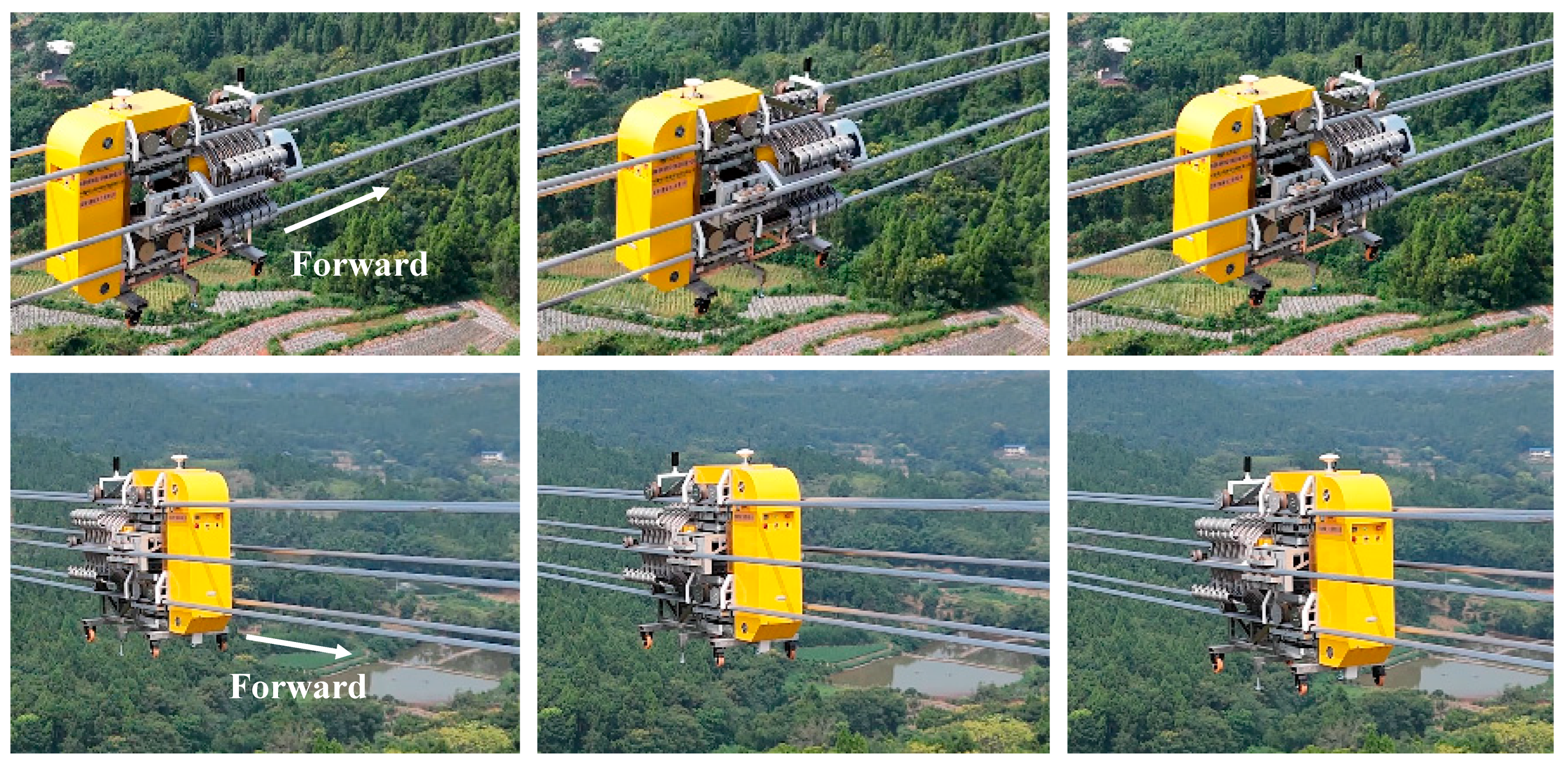
6.1. Forward Capacity Test

After measurement, the weight of the robot without the six spacers is 510 kg, and the weight of one spacer is 20 kg. The robot was placed on simulated six-split transmission lines to test the robot’s moving ability, as shown in Figure 17. The test tested the moving ability, the forward speed, and the positioning accuracy of the robot. The test results showed that the robot’s moving ability was up to 15°, the maximum forward speed was 200 mm/s, and the positioning accuracy was ±10 mm. The mobility of the robot had matched the requirements of practical engineering. The main parameters of the robot are shown in Table 1.
In order to further test the performance of the robot, the robot’s advancement system was tested on the ±800 kV DC transmission project line in Leshan City, Sichuan Province, China, as shown in Figure 18. The test results indicated that the robot could achieve constant distance and stable movement under the control of the ground operator, which provided a reliable carrier for installing spacer. The movement process of the robot is shown in Video 1 in the Supplementary Materials.

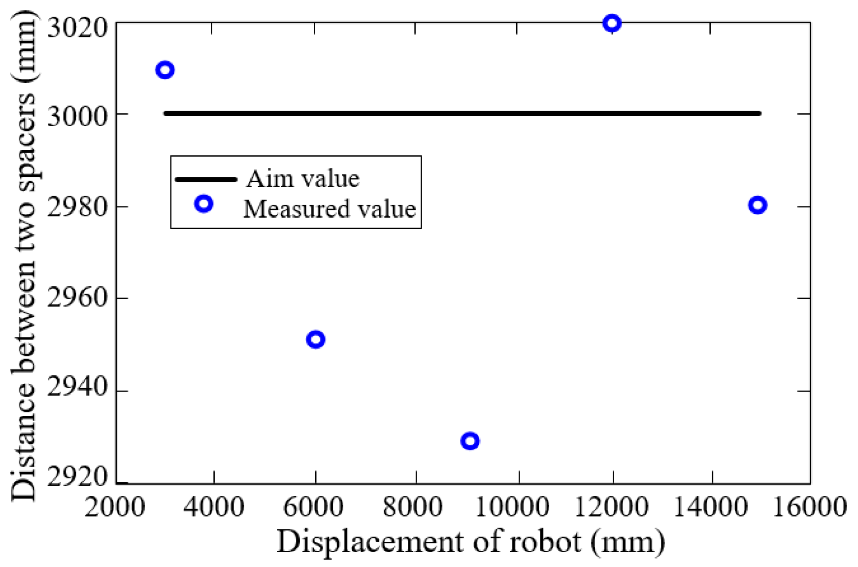
6.2. Installation of Spacers

Four workers used an electric grinder to bring the robot online on the six-split line and then calibrated chucks ① to ⑥ on the spacers to test the performance of the robot’s fully automated installation of the spacers. As shown in Figure 19, the robot is able to install the spacers, and the installation process is shown in video 2 and video 3 in the Supplementary Materials. It takes about 2 min to install a spacer chuck and about 12 min to install a Spacer. Through the test, the robot can complete the installation of six spacers at a time. Compared with manual installation, this robot does not require the adjustment of the wire spacing during installation, while workers need to adjust the wire spacing during installation, requiring longer working time and greater labor intensity. Currently, it takes workers more than 20 minutes to install a six-split spacer. When facing strong winds or a rainstorm, the manual time will be longer and more dangerous.
Further, the installation accuracy of the robot was tested. The robot was set to install spacers at intervals of 3000 mm, and after six spaces were installed, the installation accuracy of the spacers was measured. The test results are shown in Figure 20. The results indicated that the maximum deviation of the robot on the installation distance of the spacers was 70 mm, and the installation deviation ratio was 2.33%, which satisfied the installation distance accuracy requirement of the transmission line for the spacers (2.33% < 3%). It should be noted that this error is mainly caused by the robot’s small movement distance. As the robot was equipped with an RTK, when moving over long distances, the robot can reset the accumulated error through periodic absolute positioning by using the RTK, so that the error does not increase linearly with distance. Although the 3000 mm is not the actual installation distance of the six spacers, which is limited by actual testing conditions, the measurement results of the robot can prove that it has relatively accurate mobility. The test results indicated that the robot was able to install the spacers, and the installation deviation meets the engineering requirements, so the robot can replace workers to automate the installation of six-split spacers in the future.

6.3. Discussion

Compared to previous robots [32], the robot developed in this paper performs better in terms of moving with high precision, moving with high stability, closed-loop control of motors, and automated installation of spacers. This robot can work with high precision to solve the challenges during real engineering operations, which are not available in previous robots. For example, it is due to the modeling and analysis of the surface geometry of the robot’s active wheel that the robot can maintain stability for long periods while moving on the wire and during the installation of spacers.
However, there are still some challenges. When there are strong winds and vibrations in the installation environment, the relative distance between the wires will constantly change, which will cause some difficulties in the stable movement and precise operation of the robot. At present, robots can only perform installation operations when wind and line vibrations are not severe. In addition, when the outdoor temperature is low (approximately 0 °C), the endurance time of the robot will be shortened, so battery protection measures have to be designed for robots in the future. At present, it mainly relies on workers using tools to transport the robots to the transmission lines, which is due to the high weight of the robot. In the future, it is necessary to design more advanced transportation tools to simplify the process and improve the working environment for workers.

7. Conclusions

The existing six-split spacer is mainly installed manually, which has problems such as high risk and inefficiency. The two-split and four-split spacer installation robot cannot adapt to the movement and installation needs of six-split transmission lines, and cannot perform six-split spacer installation. Based on this, this paper innovatively designs a spacer-installing robot for six-split transmission lines, which can replace the manual installation of spacers. Based on theoretical modeling, the force on the wire and the cross-section form of the moving wheel of the robot were studied to provide theoretical guidance for the design of the moving mechanism. Combined with a modular design, the moving mechanism, transfer mechanism, and assembly mechanism were designed. The control of the motor was designed based on force–position coupling. The robot’s ability to move on the slope of the wire, move at a fixed distance, and install six spacers was tested, and the results indicated that the robot was able to move on a 15-degree slope on the wire, move under control, and install six spacers automatically on the wires, with an accuracy of the installation distance of the spacers of less than 3%, which is highly practical for engineering, and it can effectively replace manual work at high altitude, reduce construction risk and costs, and enhance construction efficiency.
As this robot system is heavy, it is possible to further research a lightweight design for the robot and spacer. In addition, the robot is not capable of crossing obstacles on the transmission line and can only install spacers in a single direction. Therefore, in the future, the robot needs to be designed to be able to cross obstacles. Besides the installation capability, the robot should be designed with a spacer removal capability to replace structurally damaged spacers and to enhance the robot’s intelligence. In the future, the control system and perception system of the robot will be further researched to improve the intelligence level of the present robot.

Supplementary Materials

The following supporting information can be downloaded at: https://www.mdpi.com/article/10.3390/machines13050432/s1.

Author Contributions

Conceptualization, J.P. and Y.C.; methodology, J.P. and C.H.; software, M.J.; validation, J.P. and C.H.; formal analysis, Y.M.; investigation, J.P.; resources, M.J.; data curation, F.M. and Q.S.; writing—original draft preparation, J.P.; writing—review and editing, J.P.; visualization, J.P. and C.H.; supervision, F.M. and Q.S.; project administration, C.H.; funding acquisition, Y.C. and M.J. All authors have read and agreed to the published version of the manuscript.

Funding

This project is supported by the Science and Technology Project of the State Grid (5200-202220092A-1-1-ZN).

Institutional Review Board Statement

Not applicable.

Informed Consent Statement

Not applicable.

Data Availability Statement

The original contributions presented in this study are included in the article. Further inquiries can be directed to the corresponding author.

Conflicts of Interest

Author Jie Pan was employed by the company of State Grid Electric Power Engineering Research Institute Co., Ltd. The remaining authors declare that the research was conducted in the absence of any commercial or financial relationships that could be construed as a potential conflict of interest.

References

  1. Agarwal, H.; Mukherjee, S.; Chattaraj, S.; Khan, I.; Prasad, D. Development of quad spacer damper to suppress oscillation in 765 kV transmission line. In Proceedings of the 2020 11th International Conference on Computing, Communication and Networking Technologies (ICCCNT), Kharagpur, India, 1–3 July 2020; pp. 1–6. [Google Scholar]
  2. Lee, H.K. Importance of the Spacer-Damper Installation in Overhead Lines. In Proceedings of the KIEE Conference, Kunming, China, 18–20 July 2005; The Korean Institute of Electrical Engineers: Seoul, Republic of Korea; pp. 46–48. [Google Scholar]
  3. Disyadej, T.; Kwanmuang, S.; Muneesawang, P.; Promjan, J.; Poochinapan, K. Smart transmission line maintenance and inspection using mobile robots. Adv. Sci. Technol. Eng. Syst. J. 2020, 5, 493–500. [Google Scholar] [CrossRef]
  4. Bahrami, M.R.; Abed, S.A. Mechanical challenges of electrical transmission lines inspection robot. IOP Conf. Ser. Mater. Sci. Eng. 2020, 709, 022099. [Google Scholar] [CrossRef]
  5. Li, X.; Li, Z.; Wang, H.; Li, W. Unmanned aerial vehicle for transmission line inspection: Status, standardization, and perspectives. Front. Energy Res. 2021, 9, 713634. [Google Scholar] [CrossRef]
  6. Luo, Y.; Yu, X.; Yang, D.; Zhou, B. A survey of intelligent transmission line inspection based on unmanned aerial vehicle. Artif. Intell. Rev. 2023, 56, 173–201. [Google Scholar] [CrossRef]
  7. Meng, D.; Lu, B.; Li, A.; Yin, J.; Li, Q. Pressure observer based adaptive dynamic surface control of pneumatic actuator with long transmission lines. Appl. Sci. 2019, 9, 3621. [Google Scholar] [CrossRef]
  8. Siravuru, A.; Shah, S.V.; Krishna, K.M. An optimal wheel-torque control on a compliant modular robot for wheel-slip minimization. Robotica 2017, 35, 463–482. [Google Scholar] [CrossRef]
  9. Moraitis, M.; Vaiopoulos, K.; Balafoutis, A.T. Design and implementation of an urban farming robot. Micromachines 2022, 13, 250. [Google Scholar] [CrossRef]
  10. Gao, Y.; Song, G.; Li, S.; Zhen, F.; Chen, D.; Song, A. LineSpyX: A power line inspection robot based on digital radiography. IEEE Robot. Autom. Lett. 2020, 5, 4759–4765. [Google Scholar] [CrossRef]
  11. Zorić, F.; Flegarić, S.; Vasiljević, G.; Bogdan, S.; Kovačić, Z. Autonomous Installation of Electrical Spacers on Power Lines Using Magnetic Localization and Special End Effector. Machines 2023, 11, 510. [Google Scholar] [CrossRef]
  12. Richard, P.-L.; Morin, F.; Lepage, M.; Hamelin, P.; Lambert, G.; Sartor, A.; Hebert, C.; Pouliot, N. Inside lineranger: Mechanism design to optimize operation and performances of powerline inspection robot. In Proceedings of the 2022 International Conference on Robotics and Automation (ICRA), Philadelphia, PA, USA, 23–27 May 2022; pp. 8157–8163. [Google Scholar]
  13. Qin, X.; Wu, G.; Lei, J.; Fan, F.; Ye, X.; Mei, Q. A novel method of autonomous inspection for transmission line based on cable inspection robot lidar data. Sensors 2018, 18, 596. [Google Scholar] [CrossRef]
  14. Song, Y.; Wang, H.; Zhang, J. A vision-based broken strand detection method for a power-line maintenance robot. IEEE Trans. Power Deliv. 2014, 29, 2154–2161. [Google Scholar] [CrossRef]
  15. Ma, L.; Zhang, H.; Li, Z.; He, W.; Wang, Z.; Guo, T. Research and application of automatic walking marking robot for overhead transmission line. In Proceedings of the International Conference on Computer Application and Information Security (ICCAIS 2023), Wuhan, China, 8 April 2024; SPIE: Bellingham, WA, USA, 2024; Volume 13090, pp. 1050–1057. [Google Scholar]
  16. Guo, J.; Yang, Z.; Karkee, M.; Duan, J.; He, Y. Robotization of banana de-handing under multi-constraint scenarios: Challenges and future directions. Artif. Intell. Agric. 2025, 15, 1–11. [Google Scholar] [CrossRef]
  17. Espinosa Peralta, P.; Palomino-Díaz, V.; Rodríguez Herrerías, P.; Rodríguez del Castillo, C.; Pedraza Cubero, C.M.; Yuste, J.P.; Aparicio Cillán, P.; Mesía López, R.; Águila Rodríguez, G.; Fernández Franco, V.P. ROSE: Robot for Automatic Spacer Installation in Overhead Power Lines. In Iberian Robotics Conference; Springer International Publishing: Cham, Switzerland, 2022; pp. 325–337. [Google Scholar]
  18. Wu, Z.; Zhang, J.; Chen, H.; Huang, Z. Development on robot installation using quad spacer damper. In Proceedings of the International Conference on Artificial Intelligence, Virtual Reality, and Visualization (AIVRV 2021), Sanya, China, 16 December 2021; SPIE: Bellingham, WA, USA, 2021; Volume 12153, pp. 265–272. [Google Scholar]
  19. Alhassan, A.B.; Zhang, X.; Shen, H.; Xu, H. Power transmission line inspection robots: A review, trends and challenges for future research. Int. J. Electr. Power Energy Syst. 2020, 118, 105862. [Google Scholar] [CrossRef]
  20. Mostashfi, A.; Fakhari, A.; Ali Badri, M. A novel design of inspection robot for high-voltage power lines. Ind. Robot Int. J. 2014, 41, 166–175. [Google Scholar] [CrossRef]
  21. Zhang, T.; Dai, J. Electric power intelligent inspection robot: A review. J. Phys. Conf. Series. 2021, 1750, 012023. [Google Scholar] [CrossRef]
  22. Zhu, Q.; Guan, X.; Yu, B.; Zhang, J.; Ba, K.; Li, X.; Xu, M.; Kong, X. Overview of structure and drive for wheel-legged robots. Robot. Auton. Syst. 2024, 181, 104777. [Google Scholar] [CrossRef]
  23. Pussente, G.A.N.; de Aguiar, E.P.; Marcato, A.L.M.; Pinto, M.F. UAV Power Line Tracking Control Based on a Type-2 Fuzzy-PID Approach. Robotics 2023, 12, 60. [Google Scholar] [CrossRef]
  24. Debenest, P.; Guarnieri, M.; Takita, K.; Fukushima, E.F.; Hirose, S.; Tamura, K.; Kimura, A.; Kubokawa, H.; Iwama, N.; Shiga, F. Expliner-Robot for inspection of transmission lines. In Proceedings of the 2008 IEEE International Conference on Robotics and Automation, Pasadena, CA, USA, 19–23 May 2008; pp. 3978–3984. [Google Scholar]
  25. Rui, G.; Feng, Z.; Lei, C.; Jun, Y. A mobile robot for inspection of overhead transmission lines. In Proceedings of the 2014 3rd International Conference on Applied Robotics for the Power Industry, Foz do Iguassu, Brazil, 14–16 October 2014; pp. 1–3. [Google Scholar]
  26. Zhu, A.; Tu, Y.; Zheng, W.; Shen, H.; Zhang, X. Design and implementation of high-voltage transmission line inspection and foreign bodies removing robot. In Proceedings of the 2018 15th International Conference on Ubiquitous Robots (UR), Honolulu, HI, USA, 26–30 June 2018; pp. 852–856. [Google Scholar]
  27. Gulzar, M.A.; Kumar, K.; Javed, M.A.; Sharif, M. High-voltage transmission line inspection robot. In Proceedings of the 2018 International Conference on Engineering and Emerging Technologies (ICEET), Lahore, Pakistan, 22–23 February 2018; pp. 1–7. [Google Scholar]
  28. Chen, M.; Cao, Y.; Tian, Y.; Li, E.; Liang, Z.; Tan, M. A passive compliance obstacle-crossing robot for power line inspection and maintenance. IEEE Robot. Autom. Lett. 2023, 8, 2772–2779. [Google Scholar] [CrossRef]
  29. Seok, K.H.; Kim, Y.S. A state of the art of power transmission line maintenance robots. J. Electr. Eng. Technol. 2016, 11, 1412–1422. [Google Scholar] [CrossRef]
  30. Toussaint, K.; Pouliot, N.; Montambault, S. Transmission line maintenance robots capable of crossing obstacles: State-of-the-art review and challenges ahead. J. Field Robot. 2009, 26, 477–499. [Google Scholar] [CrossRef]
  31. Pouliot, N.; Montambault, S. LineScout Technology: From inspection to robotic maintenance on live transmission power lines. In Proceedings of the 2009 IEEE International Conference on Robotics and Automation, Kobe, Japan, 12–17 May 2009; pp. 1034–1040. [Google Scholar]
  32. Pan, J.; Hu, C.; Jiang, M.; Ma, Y.; Meng, F.; He, X.; Liu, C. Development of a Spacer Bar Installing Robot for Six-Split Transmission Lines. In Proceedings of the 8th International Conference on Computing, Control and Industrial Engineering (CCIE2024), Singapore, 21–22 June 2024; pp. 11–17. [Google Scholar]
  33. Hatibovic, A. Derivation of equations for conductor and sag curves of an overhead line based on a given catenary constant. Period. Polytech. Electr. Eng. Comput. Sci. 2014, 58, 23–27. [Google Scholar] [CrossRef]
Figure 1. Workers installing spacers.
Machines 13 00432 g001
Figure 2. Effect of concentrated weight on the wire.
Machines 13 00432 g002
Figure 3. Force analysis of the moving mechanism.
Machines 13 00432 g003
Figure 4. The force analysis of the moving mechanism under the action of the pressing wheel.
Machines 13 00432 g004
Figure 5. Force analysis of the wheel with a trapezoidal cross-section.
Machines 13 00432 g005
Figure 6. Force analysis of the wheel with a curved section.
Machines 13 00432 g006
Figure 7. (a) The relative position between the clamps of the spacer; (b) the arrangement of wheels on the wires.
Machines 13 00432 g007
Figure 8. (a) The moving mechanism; (b) the effect of the six wheels on the wires; (c) the movement form of the pressing wheel.
Machines 13 00432 g008
Figure 9. (a) Storage and transfer mechanism for spacers; (b) installation effect.
Machines 13 00432 g009
Figure 10. The chuck design of the spacer.
Machines 13 00432 g010
Figure 11. Design of spacer installation mechanism.
Machines 13 00432 g011
Figure 12. Control system of the motor.
Machines 13 00432 g012
Figure 13. Integrated design of the robot.
Machines 13 00432 g013
Figure 14. Robot prototype and components.
Machines 13 00432 g014
Figure 15. The process of assembling a spacer by the mechanical arm. (a) Contacting the chuck to the wire; (b) setting the chuck in place; (c) assembling.
Machines 13 00432 g015
Figure 16. The process of installing spacers.
Machines 13 00432 g016
Figure 17. The forward ability test on the six-split line.
Machines 13 00432 g017
Figure 18. The movement test for the robot on the ±800kV transmission line.
Machines 13 00432 g018
Figure 19. The spacer installation process. (a) chuck installation process; (b) spacer installation effect; (c) multiple spacer installation effect.
Machines 13 00432 g019
Figure 20. The installation distance deviation of spacers.
Machines 13 00432 g020
Table 1. The main parameters of the robot.
NameParameters
Weight of robot G510 kg
Weight of spacer G120 kg
Maximum moving speed V200 mm/s
Maximum slope moving capability15°
Position accuracy±10 mm
Dimension2490 mm × 106 mm × 165 mm
Disclaimer/Publisher’s Note: The statements, opinions and data contained in all publications are solely those of the individual author(s) and contributor(s) and not of MDPI and/or the editor(s). MDPI and/or the editor(s) disclaim responsibility for any injury to people or property resulting from any ideas, methods, instructions or products referred to in the content.

