Article

Development of the E-Portal for the Design of Freeform Varifocal Lenses Using Shiny/R Programming Combined with Additive Manufacturing

by
Negin Dianat
1,*,
Shangkuan Liu
1,
Kai Cheng
1,* and
Kevin Lu
2
1
Department of Mechanical and Aerospace Engineering, Brunel University London, Uxbridge UB8 3PH, UK
2
Brunel Business School, Brunel University London, Uxbridge UB8 3PH, UK
*
Authors to whom correspondence should be addressed.
Machines 2025, 13(4), 298; https://doi.org/10.3390/machines13040298
Submission received: 1 March 2025 / Revised: 29 March 2025 / Accepted: 31 March 2025 / Published: 3 April 2025
(This article belongs to the Section Advanced Manufacturing)

Abstract

:
This paper presents an interactive online e-portal development and application using Shiny/R version 4.4.0 programming for personalised varifocal lens surface design and manufacturing in an agile and responsive manner. Varifocal lenses are specialised lenses that provide clear vision at both far and near distances. The user interface (UI) of the e-portal application creates an environment for customers to input their eye prescription data and geometric parameters to visualise the result of the designed freeform varifocal lens surface, which includes interactive 2D contour plots and 3D-rendered diagrams for both left and right eyes simultaneously. The e-portal provides a unified interactive platform where users can simultaneously access both the specialised Copilot demo web for lenses and the main Shiny/R version 4.4.0 programming app, ensuring seamless integration and an efficient process flow. Additionally, the data points of the 3D-designed surface are automatically saved. In order to check the performance of the designed varifocal lens before production, it is remodelled in the COMSOL Multiphysics 6.2 modelling and analysis environment. Ray tracing is built in the environment for the lens design assessment and is then integrated with the lens additive manufacturing (AM) using a Formlabs 3D printer (Digital Fabrication Center (DFC), London, UK). The results are then analysed to further validate the e-portal-driven personalised design and manufacturing approach.

1. Introduction

In today’s fast-moving world, manufacturers face increasingly tougher competition than ever before. One of the biggest challenges is that many companies, especially small- and medium-sized ones, cannot keep up with every part of the supply chain. It is hard for them to manage every process—from obtaining raw materials to handling design, manufacturing, and finally delivering the products to customers—in an agile and timely responsive manner [1]. Additionally, a fast response to customers is a key factor, alongside delivering high-quality products and reducing production costs. As markets become more global and fast-changing, the ability to adapt effectively is more important than ever. In this regard, agile manufacturing and e-manufacturing are becoming essential for achieving the above business goals [2].
The primary focus of the research presented in this paper is to develop an online platform that fills the gap between the customer’s order and the manufacturing processes for designing and manufacturing varifocal lenses, enhancing the lens-led process with a more customised experience. Lens design and manufacturing are highly customised for personalised products since each customer has their own unique individual requirements. Varifocal lenses, also called variable-focus or multi-focal lenses, were mainly used to correct presbyopia, a condition in which the eye’s crystalline lens becomes rigid, and the ciliary muscle loses flexibility, making it difficult to focus on close objects. Traditional glasses cannot address both far- and near-vision issues; in this regard, varifocal lenses were invented but had limitations in visual quality due to their design [3,4].
In recent years, R, a free and open-source software widely used by statisticians and data scientists, has become increasingly popular. This rise in popularity is thanks to the increasing number of packages that make web-based development much more efficient and effective. One of R’s standout features is its ability to produce powerful and customisable statistical graphics. The Shiny package, in particular, has made it easy to create interactive data applications that users can access from any computer [5]. Users can input the individual parameters of their eye prescription details, and then through the Progressive Addition Lens (PAL) modelling algorithm in [6], a customised freeform varifocal lens surface is generated. This e-portal serves as the core of the manufacturing process of the unique varifocal lens design [3]. Additionally, by obtaining the data points of the surface, ray tracing technology can be employed for the virtual quality assessment of the lenses.
Based on recent research conducted by Liu, Cheng, and Zhao in 2023 [3], an e-portal in Shiny was developed. This paper presented an online system for creating customised lenses; the system works in three steps: first, it takes the customer’s prescription information; second, it creates a 3D computerised model of the lens; and finally, it uses ultra-precision machines to make the actual lens based on this model.
Another aspect of this paper involves adding advanced artificial intelligence (AI) features to the manufacturing process of lens design, which helps manufacturing companies remain competitive, innovative, and adaptable. For instance, the HSO group Amsterdam, Netherland, helps companies remain competitive in markets through the power of Microsoft’s latest cloud and AI technologies. Additionally, AI-powered tools like Microsoft’s Copilot are being widely used to help manufacturing teams make better decisions. These tools enable real-time insights, streamline operations, and encourage better collaboration across teams, making them smarter, faster, and easier to use [7]. Big tech companies are racing to include these tools in their software to improve user experience and efficiency [8]. Since lens selection is a unique process and needs to be personalised, both manufacturers and users need a platform where they can ask questions in a conversational way and receive clear, helpful information. For manufacturers, this ensures they can easily navigate the design and production process, while for users, it provides guidance to make informed choices about their lenses and frames. By offering AI-powered conversations, the platform helps streamline decision-making, making the experience smooth, informative, and supportive for everyone involved.
Large language models (LLMs), such as GPT-4 [9], are powerful AI systems designed to understand and generate human-like text. They are defined by the large number of parameters they contain. These parameters are the building blocks that help the model learn patterns and are the connections within the data it was trained on. The more parameters a model has, the better it can grasp the complexity of the language, enabling it to perform tasks like writing, answering questions, and holding conversations more effectively [8].
The main difference between LLMs and the Microsoft Copilot platform comes down to how they are used. LLMs are versatile and can handle a wide range of tasks while Copilot platforms are more focused and designed to help with specific tasks; they can work with fewer data sources, which, in general, can provide more accurate answers to users [10].
For example, in the field of lens designing, an AI copilot can help users, patients, or manufacturers choose the best lenses and frames by considering factors like comfort, budget, and lifestyle. This makes the entire process more efficient and tailored to individual needs. By working together, LLMs and Copilot platforms show how AI can drive innovation, make work easier, and create a better overall experience for both developers and users. To provide a clear idea of how this personalised platform works, a demo website link can be found on the created Shiny dashboard, which is available for users to explore.
Based on the given framework in Figure 1, the online portal enables users, including optometrists, lens manufacturers, and patients, to design customised varifocal lenses using optical parameters, 2D contour plots, and 3D surface plots. This portal also provides an Excel file for data points of the surface for further assessment.
To generate the surface of optical lenses, advancements in freeform surface technology have enabled complex geometric designs to move beyond traditional symmetrical shapes like conics and spheres. Also, this technology can significantly reduce optical aberrations while minimising the overall size and weight of the lens [3,11]. Lens material and surface geometry are two crucial optical properties of modern ophthalmic lenses. Material selection influences factors such as thickness, weight, and optical properties in lenses, and the widely used materials are glasses and plastics [12].

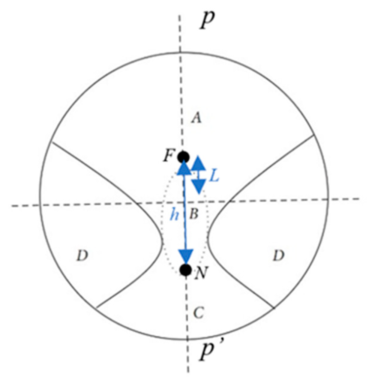
1.1. Freeform Surface Design of Varifocal Lens

“Freeform surfaces can be defined as surfaces with no axis of rotational invariance” [13,14]. In designing the surface of varifocal lenses, progressive addition lenses (PALs) can meet the need for clear vision at both far and near distances, providing a continuous field of view and offering a more comfortable wearing experience. In this regard, as shown in Figure 2, four different zones are considered, as follows: zone A is for distant vision; zone C is for near vision and reading; zone B is the progressive corridor connecting far and near zones, providing smooth continuous vision that is also the design’s main focus [6]; and zone D is the peripheral zone, where astigmatism is inevitable [15].
The ability of an ophthalmic lens to bend or refract light is generally expressed by its vertex power. The vertex power is the inverse of the lens’s focal length measured in metres. Its unit is called Dioptre, represented by the symbol D [6].
Many methods for designing PAL surfaces have been developed, such as the Winthrop method [16], the Maitenaz method [17], and the Steele method [10]. When comparing these methods, it is important to mention that all methods are based on a few different principles. The Winthrop method, which is also the main core of the PAL design process of the varifocal lens in this project, was invented by John T. Winthrop in 1989. Based on this method, the curvature radius must change smoothly along the meridian line, with gradual changes around the far-view and near-view zones [15]. This ensures that the variation in curvature is continuous. Based on the method provided by Wei [6] in 2020, which is also based on the Winthrop method, a Cartesian coordinate system is considered, where the PAL surface is tangential to the vertical plane, as shown in Figure 3.
Any point at the meridian line is called Q ( u , 0 , z ) . Additionally, any q ( ε , η , ζ ) point is known as the curvature centre of Q. In this regard, r = Q q is the curvature radius of point. Equation (1) represents the Dirichlet integral, in which m and l are, respectively, the first-order terms, ensuring that d n D ( x , 0 ) d x n is not zero at the distant and near views.
F N | d m + l 1   D ( x , 0 ) d x m + l 1 | 2 d x
To ensure that the transition is smooth at the far- and near-vision zones, the order of the first nonzero derivative should be high. Based on the Euler–Lagrange equation and boundary conditions, Equations (2) and (3) are obtained as follows:
D ( x , 0 ) = D D + ( D R D D ) i = 1 m + l 1 c i ( x + L ) i
i = 1 m + l 1 c i h i = 1
Since the vertex power is calculated based on Equations (1)–(3), by entering proper parameters for l, m, h, and L, and knowing the definitions of Q , q , and r , the curvature radius at any point on the front surface of the lens is calculated as shown in Equation (4):
1 r ( u ) = 1 r D + ( 1 r R 1 r D ) i = m m + l 1 c i ( u + L ) i
The PAL surface can be derived by selecting the appropriate contour curve u ( x ,   y ) and substituting it into the relevant equations [3,6].

1.2. The Role of 3D Printing in Lens’s Customised Design

Three-dimensional (3D) printing originated in 1984 by Charles Hull as a layer-by-layer process called “stereolithography”, using ultraviolet (UV) light to solidify liquid plastic. By adding one layer after another, an object with a certain shape can be built up, While the core concept remains [18,19], 3D printing was also called rapid prototyping, solid freeform fabrication, layered manufacturing, or other names [18]. This original concept of building objects layer by layer is still used in some 3D printers today. However, the quality, accuracy, and range of materials that can be used for 3D printing machines have increased over time and the technology has advanced dramatically since its early beginnings [20].
The AM process—when compared to traditional manufacturing methods such as non-uniform rational B-spline (NURBS) [21] and ultra-precision machining (UPM) [22,23]—is more flexible for complex shapes; it not only saves time but also significantly reduces material waste, making it a more efficient and sustainable option for optical component manufacturing [24]. While UPMs, such as single-point diamond tuning (SPDT) [23] and the fast tool servo (FTS) [25], are highly effective for producing components with extremely tight tolerances, they are considerably more complex and costly since these advanced processes often involve specialised equipment, skilled operators, longer setup times, and higher maintenance costs. As a result, the overall investment required for the AM process for optical lenses is significantly less compared to traditional methods, making it more suitable for small- and medium-scale manufacturing companies, leading to mass customisation production of personalised products.
The process of creating a 3D varifocal lens begins with a digital design file representing the 3D model [26], such as “STL”, “OBJ”, and “AFM” formats.
According to research conducted by Christopher [27] in 2024, the process of creating a 3D-printed model for a varifocal lens involves four main steps, as follows:
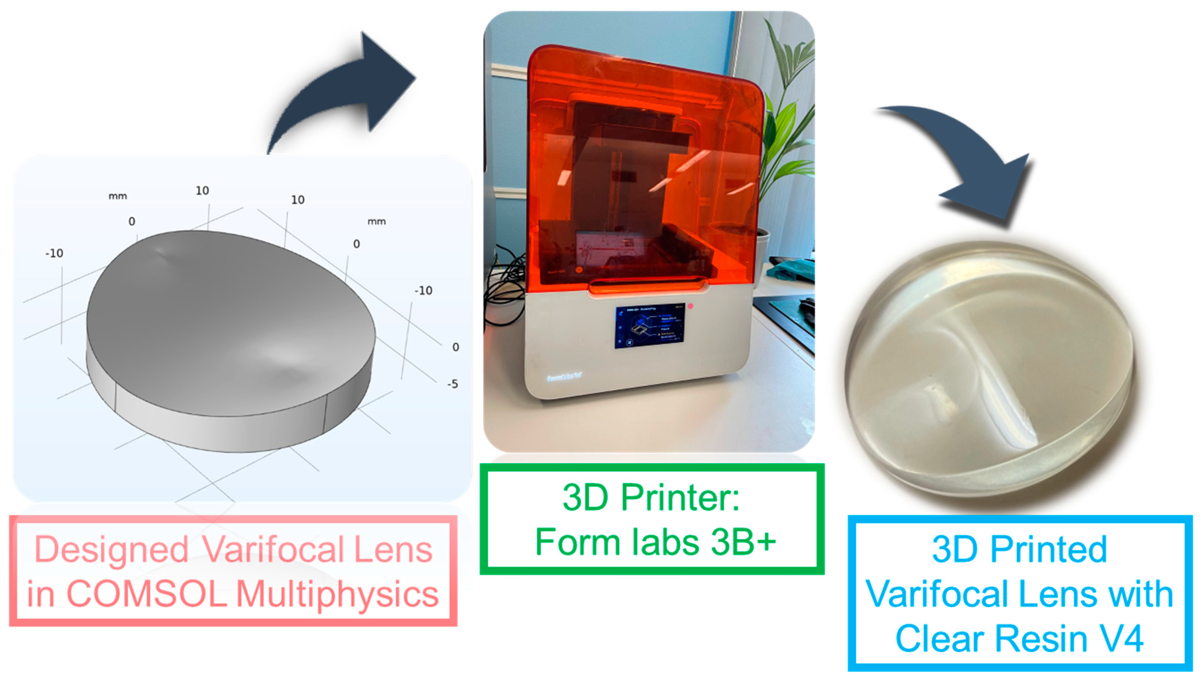
  • Designing the lens using CAD software (COMSOL-Multiphysics 6.2).
  • Converting the designed model to a 3D printer file format.
  • Optimising the printer settings.
  • Material selection for the 3D-printed model.
In this regard, it is necessary to define the material that is suitable for the desired varifocal lens as well as find the best 3D printer.

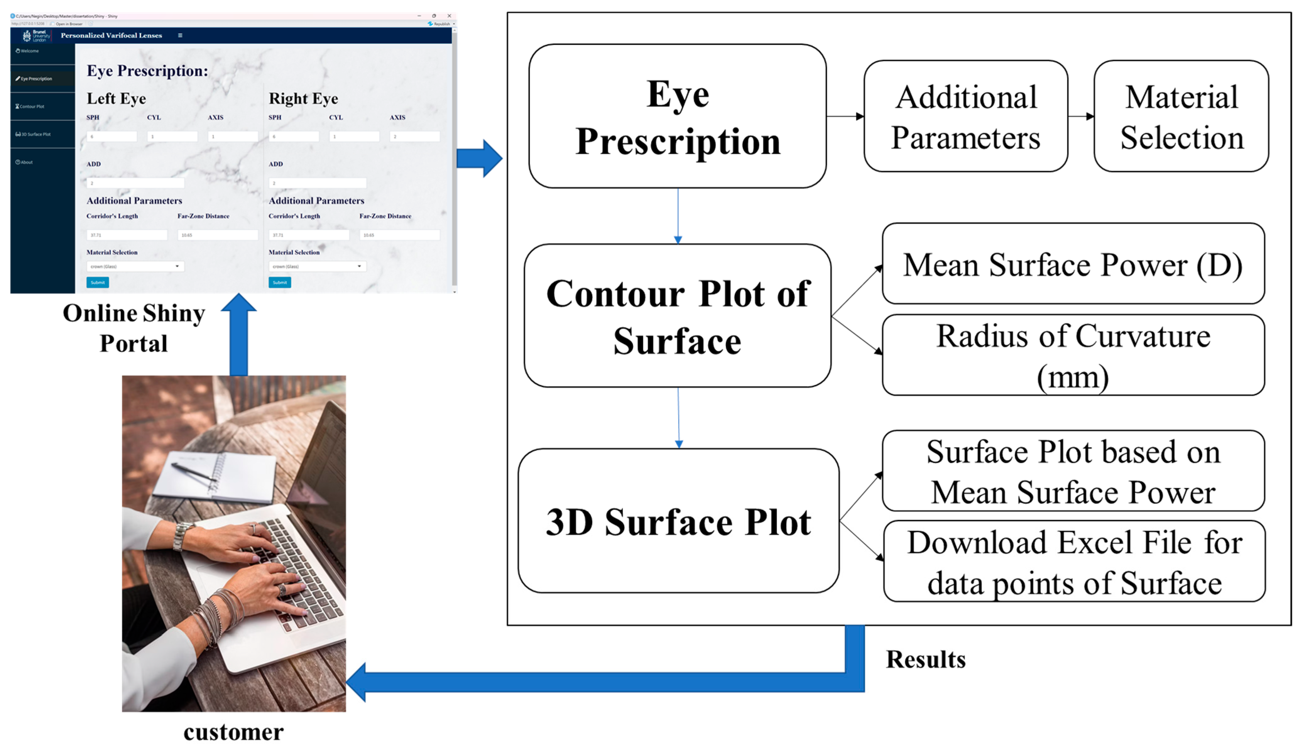
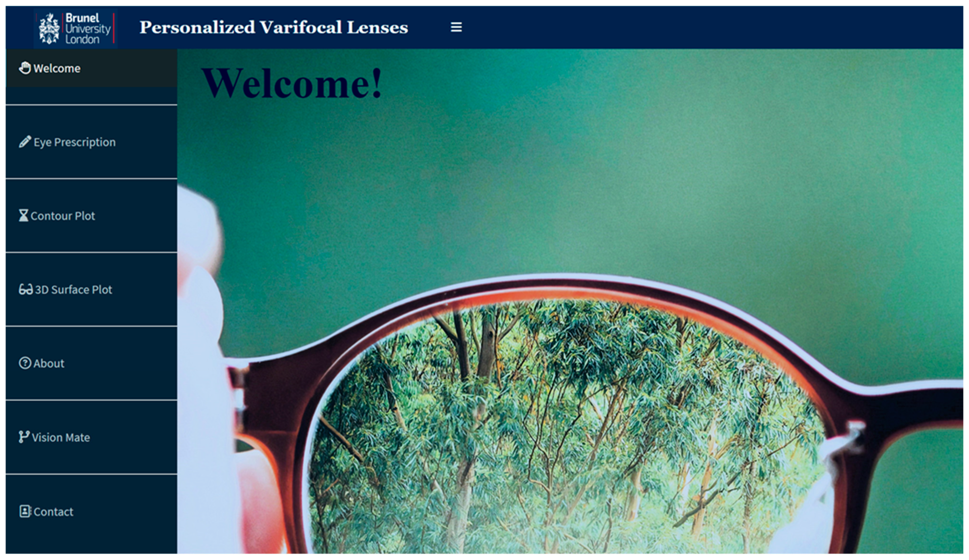
2. Module Structures and Development

The design and analysis modules are vital and core elements of the system [3]; therefore, it is essential to provide a clear module structure.
As shown in Figure 4, the main concept of this project is to provide an online platform to first model the surface of the varifocal lens using the Shiny web application. The platform can be accessed at “https://personalized-varifocal-lens.shinyapps.io/varifocal/ (accessed on 9 January 2024)”. This prospective online platform can provide a surface data point cloud in the format of an “xlsx” file. Then by importing the data into COMSOL Multiphysics 6.2, the 3D model of the desired lens can be modelled. It is also very essential to conduct the surface ray tracing assessment in this platform to check the performance of this lens.
When the design process with COMSOL 6.2 is completed, by changing the format to an STL file and importing the file to the desired 3D printer, the initial version of the lens is created. For the optical lenses, the roughness must be less than 50   nm , and in order to achieve this surface roughness by sand polishing the surface of the lens, a roughness of 40   nm can be achieved.
In this project, the “Shiny dashboard” is the main package that will help one design the surface of a varifocal lens and it also enables linking to a Microsoft 365 Copilot demo web, called Vision Mate. The “Shiny dashboard” library, building on top of Shiny, provides a more structured and dashboard-like layout for Shiny apps. It includes components like sidebars, headers, boxes, and other elements commonly found in dashboard applications [28].
Since GitHub Copilot 5 was introduced, the term “copilot” has become widely used in the software engineering world to refer to software tools that use LLMs to help users with different tasks [8]. In this project, the “Vision Mate” copilot is specifically designed for users to answer specialised questions related to lenses and glasses; it can be used by both general users and manufacturers.
As shown in Figure 5, the dashboard section provides an overview of the main parts of the Shiny portal, including the parameter section inputs and the plot results.
This Shiny platform not only designs the freeform surface of lenses but also works as a connection platform to link this interface with the AI demo web called “Vision Mate”. This demo web is specifically created with Microsoft 365 Copilot to guide users through a conversational interface to fulfil their needs, which will be explained more in the following section.

3. Vision Mate and Its Implementation

Nowadays, AI is being widely used. These AI systems are working more closely with people, handling repetitive tasks so employees can concentrate on more challenging and creative work. This teamwork helps boost overall productivity and allows humans to contribute where they are needed most [29].
Mostly, AI platforms will guide users in general form; if a more specific and detailed question is asked of them, they can usually answer in a general way. In this case, having an AI copilot can be a game-changer for lens manufacturers. In such a specialised industry, research and finding the right information can take a lot of time, and time is one of the most essential components in today’s markets and industries. A copilot helps speed up this process by providing quick and accurate answers, so teams do not have to waste hours digging through data or troubleshooting problems.
This kind of support is key to staying flexible and efficient in manufacturing, where speed and precision matter. With a copilot, manufacturers can easily optimise their workflows, solve issues faster, and improve designs without unnecessary delays. Plus, since the copilot can pull insights from reliable open-source resources, it offers guidance that is always current and accurate. This means better productivity, more room for innovation, and consistently high-quality lenses.
In this project, Vision Mate is creating a web platform that can be used by both manufacturers and users who want to obtain general information. This interactive demo makes it easy for users to find the perfect lenses and frames by guiding them through each step of the process. It takes into account important factors like comfort, budget, vision needs, and lifestyle to offer personalised recommendations that truly fit each user. Not only does it help with selecting the right lenses, but it also provides practical advice on lens materials, coatings, and how to obtain the right frame fit. It even considers environmental factors, such as the user’s local climate or weather conditions, to make sure the choice suits the user’s day-to-day life.
What makes this demo even more powerful is its information resources. Trusted open sources, like the websites of known companies, e.g., IOT lenses [30], Essilor [22], Spec-Savers [31], and Vision-Express [32], have been used to build a comprehensive library of eyewear knowledge. These websites cover everything from the latest lens technologies and frame designs to tips on maintenance and care. By asking a specific question about lenses or frames, the demo not only provides a clear and accurate answer but also provides links to these reliable sources for more in-depth reading.
Figure 6 illustrates the appearance of the created demo web; by clicking on the hyperlink provided on the main Shiny dashboard, users can directly move to this platform on a new web page other than the Shiny one.

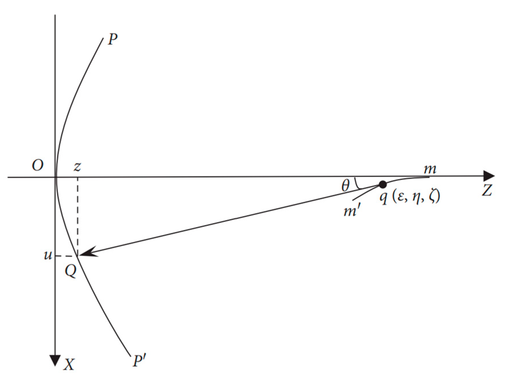
4. Freeform Surface Modelling

Describing a freeform surface mathematically involves both local and global approaches. In the local approach, data points of the surface are individually described [33], whereas, in the global approach, the entire surface is described with a single mathematical formula [13]. Both approaches have their uses, depending on the requirements for surface description.
To create the lens surface, four different parameters are used—“SPH”, “CYL”, “AXIS”, and “ADD”—based on individualised eye prescriptions. The list of optical parameters, which can be found on the individualised eye prescription, is given in Table 1.
The “SPH” value on eyeglass prescription represents the spherical power of the lenses. This spherical component corrects refractive errors, like near-sightedness (myopia) or far-sightedness (hyperopia). The “CYL” value represents the cylindrical power needed to correct astigmatism, indicating the imperfection in the curvature of the eye’s cornea or lens. The “AXIS” number on the eye prescription indicates the orientation or angle at which any cylindrical power (for correcting astigmatism) should be positioned in the lens. This number ranges from 1 to 180 degrees. Specifically, an axis of 90 degrees means the cylindrical power should be aligned vertically, while 180 degrees signifies a horizontal alignment [31]. Additionally, for varifocal lenses, the “Add” value shows the power of the near-vision zone of the lens [3] Geometrical parameters, which are needed for varifocal lens surface design, are given in Table 2. In this case, two more values are needed, namely, “Corridor length” and “Far-zone distance”, denoted as h and L in Figure 2, respectively. Additionally, by selecting the lens material through a list in the portal, the refractive index n is chosen.
The mathematical calculations for lens surface generation were implemented using the R programming language. The script includes the necessary computations to generate the lens’s surface, producing the intended outputs. In this regard, this portal uses Winthrop’s [16] model functions to create the PAL freeform surface of the varifocal lens. The lens is defined by a polynomial power law of the 8th order; by defining the order in Function (4), the function is expressed in (5):
1 r ( u ) = 1 r D + ( 1 r N 1 r D ) × i = 1 8 c i ( u + L ) i
where c i denotes constant coefficients, r D represents the distant power, r N denotes the near power of the lens, which is related to the refractive index, SPH, and ADD values, as shown in Equations (6) and (7):
r N = ( n 1 ) × 1000 S P H + A D D
r D = ( n 1 ) × 1000 S P H
The function u ( x , y ) essentially assigns each point on the surface where its level curve crosses the x-axis. After performing detailed mathematical calculations and analysis of this relationship using the Winthrop method [16] by Wei [6], u ( x , y ) is calculated.
The progressive varifocal lens surface, denoted as f ( x , y ) , is defined by a specific set of mathematical equations given in (8). These equations determine the precise shape and properties of the surface, which are given in [16]. Various designs of the surface are generated through different mathematical functions that define the meridional power law, represented as r ( u ) . By changing this function, different embodiments of the surface can be created [3,6,16].
f ( x , y ) = b ( u ) { r ( u ) 2 [ x a ( u ) 2 ] y 2 } 1 2
After defining the bipolar progressive surface z ( x , y ) through a list of mathematical equation codes written in R-Script language, the next step involves featuring the given results throughout the Shiny online portal to the customers in the form of plots and diagrams.

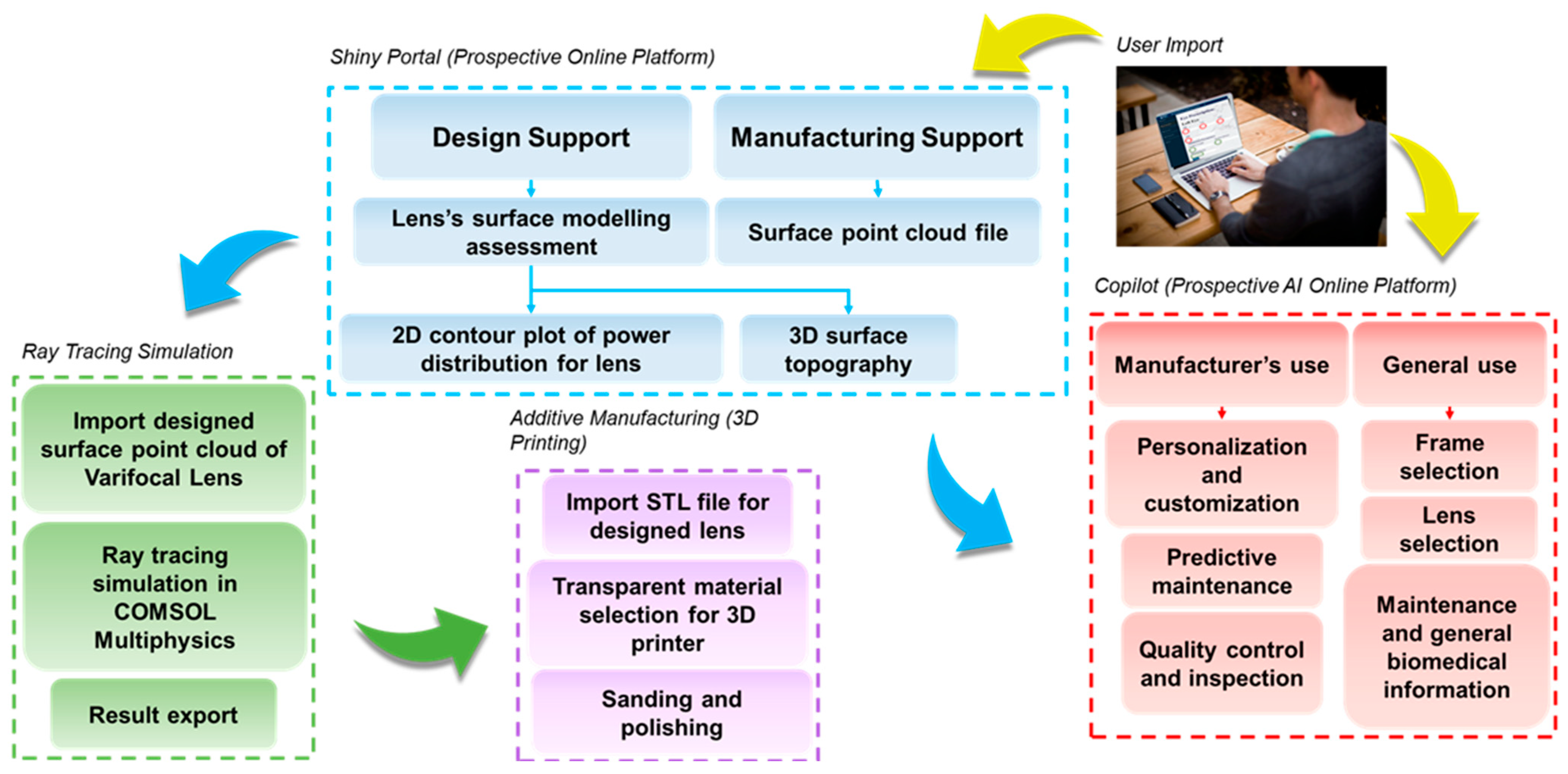
5. Lens Surface Assessment

By focusing on the key optical properties of the designed surface of the varifocal lens, our analysis is divided into two main parts:
  • The 2D contour plots and 3D surface plots, which are representations of the designed surfaces for varifocal lenses.
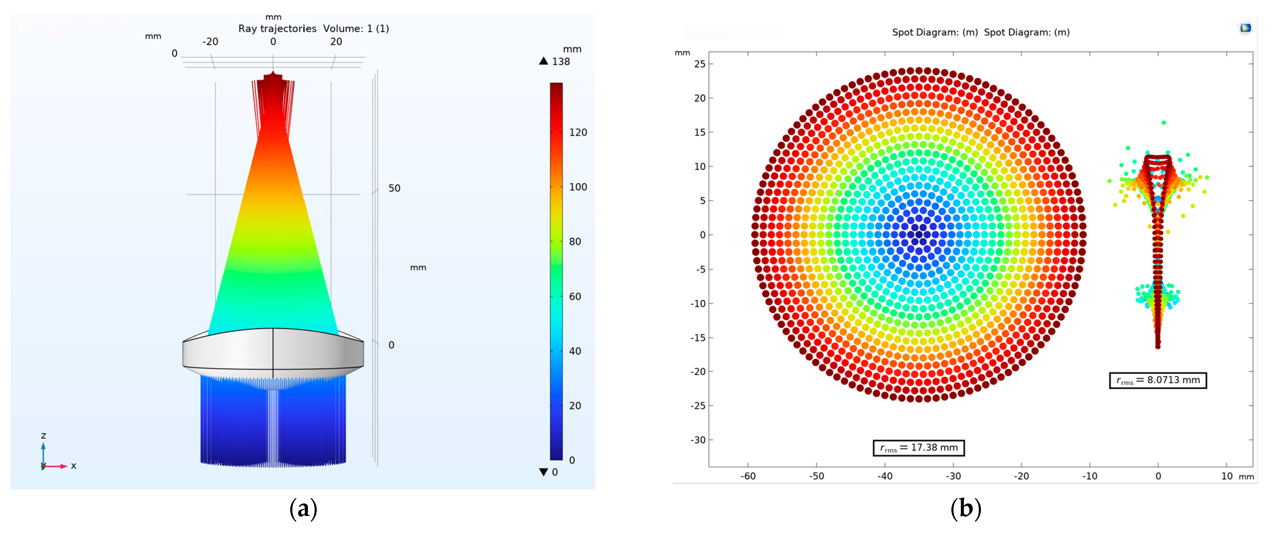
  • Ray tracing assessment, which is based on the modelled surface in COMSOL Multiphysics 6.2—a powerful simulation modelling software that is widely used in engineering and scientific research—using the data points from the designed lens in the Shiny online web portal.
Through the Shiny portal, the parameters given in Figure 7 are defined, and further results are based on them.

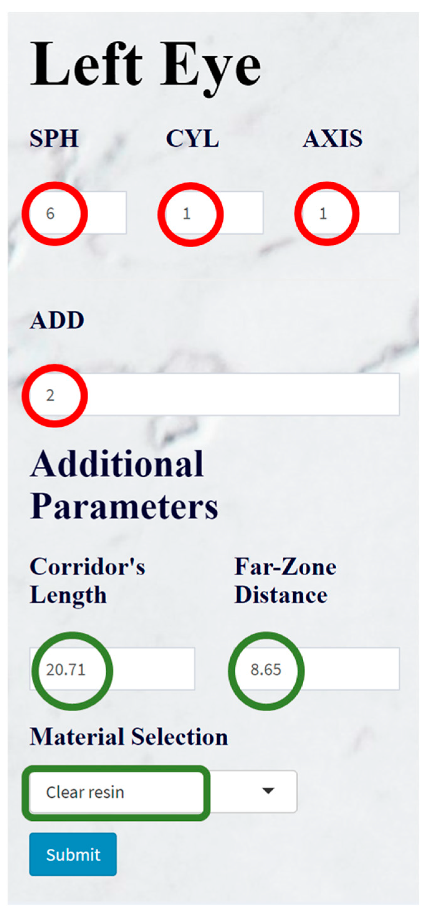
5.1. Results: PAL Surface for Varifocal Lenses Through the E-Portal

To evaluate the results for designing a freeform surface with the previously mentioned equations provided through R Script and linked with this online Shiny portal, a set of default assumptions for the input values has been established, as shown in Figure 7. These predetermined parameters serve as a starting point for our analysis, allowing us to assess the outcomes of the equations. It is evident that the process is identical for both the right and left eyes.
In the “Contour Plot” section of the portal, the contour plots that illustrate the radius of the curvature and surface power across the lens based on the previous input data are given in Figure 8. These 2D visualisations offer a clear view of how these critical parameters vary over the lens surface.
As shown in Figure 9, the near-vision power value of the lens is 6.2 (D), which closely matches the customer’s given spherical power value. Also, the difference between the near- and far-vision power of the designed lens is roughly 1.6 (D), which closely matches the addition power with a difference of 0.4 (D). Additionally, in the “3D surface plot” section, the three-dimensional distributions of the varifocal lens surface and surface power are given, as shown in Figure 10. These 3D plots provide a more intuitive understanding of the lens geometry and optical characteristics. The data results are automatically saved as an EXCEL file, representing the data points ( x , y , z ) of the designed freeform surface. By changing any parameter in the portal, the new database will immediately change. Following this, the next step is to verify whether this designed surface has the requirements of an optical varifocal lens.

5.2. Lens Design

5.2.1. AM for Varifocal Lenses

Varifocal lenses are marketed as ‘all-purpose’ solutions, implying that they aim to provide a balanced performance between distance and near-vision needs. However, this approach restricts the variety of viewing zone configurations available to users. In contrast, customised progressive lenses created through freeform surfacing technology are not bound by such limitations. While selecting a lens based on the measurements of viewing zones does offer some flexibility, this method has its drawbacks. It relies on having access to precise evaluations of each lens’s optical performance, which may not always be readily available or easily obtainable. This lack of comprehensive performance data can make it challenging for eye care professionals and consumers to make fully informed decisions when choosing the most suitable lens design for individual needs. The advent of freeform technology in lens manufacturing has opened up new possibilities for tailoring progressive lenses to specific visual requirements, potentially offering a wider range of viewing zone balances than traditional designs. This customisation capability could lead to more personalised and effective vision solutions for individuals with varying visual needs and preferences [34]. In order to create the 3D model of the varifocal lens in the COMSOL Multiphysics 6.2environment, the imported data point cloud of the designed PAL surface in the Shiny portal is considered as both the back and spherical surfaces, with a power of 0 (D) for the front section of the lens, as shown in Figure 11.
In Figure 12, the framework of the 3D printing assessment is shown. During this process, the designed 3D model in COMSOL Multiphysics 6.2 is converted into the STL format, which can be read by the desired 3D printer; in this case, “Formlabs 3B+” is chosen, which is used for small components like lenses and other medical and healthcare uses [35]. The selected material must be transparent; in this case, “Clear Resin V4” is chosen. The refractive index of Clear Resin is reported as 1.5403 by the Formlabs supplier [36]. Additionally, the dispersion of a specific material is typically represented by a single parameter called the Abbe number, which is defined as follows:
v d = n d 1 n f n c
where in (9), n d , n c , and n f represent the refractive indices measured at the Fraunhofer spectral lines d (587.56 nm), c (656.28 nm), and f (486.13 nm), respectively [12]. The Abbe number for Formlabs Clear Resin, calculated using the refractive index values reported in [37], is found to be v d = 56.44 [38]. Thanks to modern 3D printing technology and other opportunities for designing varifocal lenses through online web platforms like the Shiny dashboard, the actual preferred lenses can be made. Table 3 illustrates the key parameters for the sample 3D-printed varifocal lens, and the printed varifocal lens is shown in Figure 13.
The form accuracy (<5 µm) and surface roughness (<20 nm) of the lenses can be achieved through the additive manufacturing process, although the additive manufacturing of the lenses is more for evaluation and validation of the integrated approach for design, manufacturing, and virtual assessing the lenses.
The available 3D printers are limited in terms of materials for good optical performance; as mentioned before, choosing an appropriate material is essential. Using Clear Resin as the lens material can lead to colour changes that compromise visual clarity; although UV light treatment can correct this, it is difficult and uncomfortable for users, making multi-material 3D printing a promising alternative. In the future, exploring new materials or refining post-processing methods, like polishing or applying special coatings, could help overcome some of the challenges like surface imperfection.

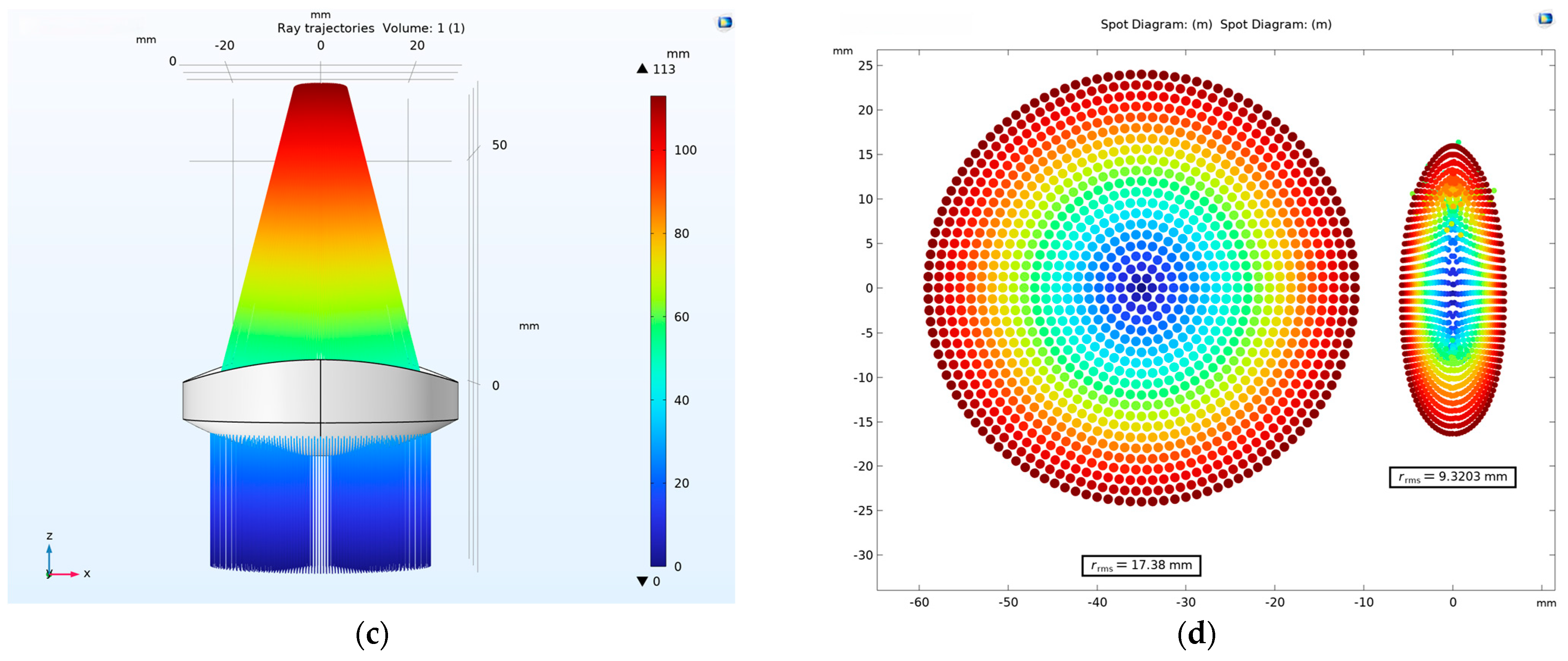
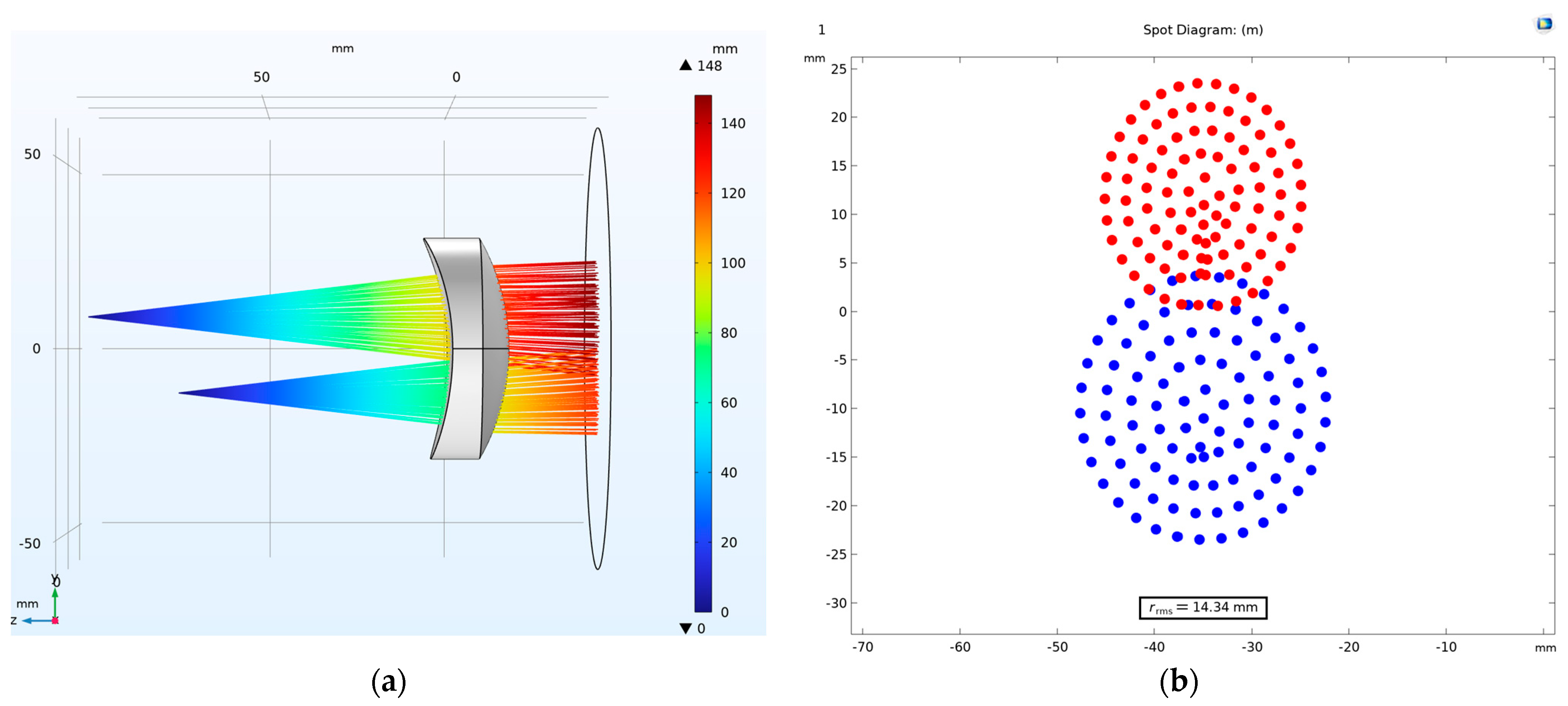
5.2.2. Ray Tracing Assessment and Validation

It is necessary to check the performance of the designed lens to make sure it meets the necessary requirements. In this regard, the ray-tracing method with the help of COMSOL Multiphysics 6.2 was employed for the previously designed freeform surface through the Shiny portal. Once the 3D model in COMSOL Multiphysics 6.2 is ready, as shown in Figure 11, the next step is to set up the simulation environment. These settings are essential to ensure the simulation accurately reflects real-world optical conditions and delivers useful results.
The ray-tracing simulation setup follows the guidelines of the ISO 8980 standard [39] for ophthalmic optics. This standard provides a framework [40] for setting up a physical inspection system to evaluate the performance quality of the varifocal lenses. It also serves as a reference for carrying out accurate digital inspections of optical products. The next step involves setting up the simulation parameters, which are given in Table 4. To obtain accurate and meaningful results, it is essential to choose the right simulation parameters carefully. These parameters shape how the model behaves optically and ensure that the simulation reflects how the freeform surface is meant to perform.
To further support the simulation results, an inverse method was then used. In this approach, light rays were sent out in a conical pattern from the two set focal points, one for the near-vision zone and one for the far-vision zone. The simulation followed these rays as they moved through the lens; the following key observation was made: when the rays left the lens, they came out approximately parallel. The fact that the rays came out parallel shows that the focal points were correctly set, and the lens’s optical properties matched the intended design.
Figure 14 illustrates the spot diagrams and ray paths obtained from the forward method for both the near- and far-vision zones, highlighting the regions where light bending is maximum.
Figure 15 shows the spot diagrams and ray paths from the inverse method, clearly showing how the conical rays turn into a roughly parallel beam after passing through the lens. The combined evidence from both methods validates the COMSOL 6.2 simulation setup based on the ISO 8980-1:2004 standard, confirming that the varifocal lens model accurately reproduces the expected optical performance. Additionally, it is useful to understand that RMS, given in spot diagrams of ray tracing assessment, is a comprehensive optical assessment metric value that provides a clinically meaningful evaluation of optical performance, giving eye care professionals a general understanding of the designed progressive and freeform varifocal lens performance [34,41].
In this study, the validation of the COMSOL Multiphysics 6.2 simulation for the designed varifocal lens was conducted using two complementary methods. First, a forward ray-tracing method was used, where light rays were sent from a fixed distance of 40   ( mm ) from the outer spherical surface of the lens. The simulation produced spot diagrams for both the near- and far-vision zones. These diagrams were then analysed to ensure that the maximum bending of light happened at the focal points predicted in Equations (7) and (8), with calculated focal lengths of approximately 73.75   ( mm ) for the near-vision area and 98.33   ( mm ) for the far-vision area. This step confirmed that the lens was focusing light correctly, as expected from the design.

6. Conclusions

This paper presents an innovative e-portal-driven solution to the personalised varifocal lens design and manufacturing process, enhancing the agility and responsiveness of lens manufacturers in a competitive market. Leveraging the capabilities of R programming and the user-friendly Shiny interface, the e-portal allows optical engineers to efficiently handle the complexities of varifocal lens design. The system allows customers to input their design requirements and instantly visualise the resulting lens geometry and contour plots, significantly reducing production time for both manufacturers and end-users.
In terms of academic contribution, this work offers a novel approach by merging design, additive manufacturing, and virtual assessment into a seamless, automated process. Key contributions include the following:
  • Development of an interactive intelligent e-portal that automates and streamlines the lens design and manufacturing workflow, increasing efficiency in optical engineering.
  • A seamless fusion of design, additive manufacturing, and virtual assessment, which replaces traditional multi-step fabrication, creating benefits such as mass customisation, faster production cycles, and reduced material waste in order to save resources.
  • Automated design and manufacturing processes that facilitate rapid prototyping and the customisation of lenses, enhancing the ability to meet individual customer needs and minimise process inconsistencies.
Looking ahead, several future perspectives offer opportunities for further advancement and optimisation of this approach:
  • Enhancing material selection and post-processing techniques to improve optical performance, enabling greater precision and durability in the final product.
  • Experimental validation of the fabricated lenses, including surface accuracy, refractive index control, and other key optical properties.
  • Incorporating AI-driven design optimisation into the e-portal to further streamline the design process and improve the customisation capabilities of the system.
While challenges remain, particularly in transparent 3D-printed materials, continued developments in this field promise to overcome these limitations and facilitate the broader adoption of additive manufacturing for personalised lenses. This integrated approach, combining digital design, AI support, and advanced materials, opens up new opportunities in the ophthalmic optics industry, providing efficient and scalable solutions for mass-customising varifocal lenses.

Author Contributions

Conceptualization, N.D., S.L., K.C. and K.L.; Methodology, N.D. and S.L.; Software, N.D. and S.L.; Validation, N.D.; Formal analysis, N.D.; Investigation, N.D. and K.C.; Resources, N.D., S.L., K.C. and K.L.; Data curation, N.D.; Writing—original draft, N.D.; Writing—review & editing, K.C.; Visualization, N.D., S.L. and K.C.; Supervision, S.L. and K.C.; Project administration, K.C. All authors have read and agreed to the published version of the manuscript.

Funding

This research received no external funding.

Data Availability Statement

The original contributions presented in this study are included in the article. Further inquiries can be directed to the corresponding author.

Conflicts of Interest

The authors declare no conflict of interest.

References

  1. Toussaint, J.; Cheng, K. Implementation of design agility and manufacturing responsiveness on the web: Two case studies. Integr. Manuf. Syst. 2002, 13, 328–339. [Google Scholar]
  2. Cheng, K.; Bateman, R.J. e-Manufacturing: Characteristics, applications and potentials. Prog. Nat. Sci. 2008, 18, 1323–1328. [Google Scholar] [CrossRef]
  3. Liu, S.; Cheng, K.; Zhao, L. Development of the personalised manufacturing system framework for freeform vari-focal lenses and its implementation and application perspectives. Int. J. Mechatron. Manuf. Syst. 2023, 16, 1–21. [Google Scholar]
  4. Groover, M.P.; Jayaprakash, G. Automation, Production Systems, and Computer-Integrated Manufacturing, 4th ed.; Pearson: London, UK, 2016; Available online: https://go.exlibris.link/nclTmZ3v (accessed on 28 September 2024).
  5. Beeley, C. Web Application Development with R Using SHINY; Packt Publishing Ltd.: Birmingham, UK, 2016. [Google Scholar]
  6. Wei, Y.; Zhai, P.; Chen, X.; He, L. Study on design and diamond turning of optical freeform surface for progressive addition lenses. Math. Probl. Eng. 2020, 2020, 2850606. [Google Scholar]
  7. HSO. 2024. Available online: https://www.hso.com/ (accessed on 27 October 2024).
  8. Parnin, C.; Soares, G.; Pandita, R.; Gulwani, S.; Rich, J.; Henley, A.Z. Building your own product copilot: Challenges, opportunities, and needs. arXiv 2023, arXiv:2312.14231. [Google Scholar]
  9. Achiam, J.; Adler, S.; Agarwal, S.; Ahmad, L.; Akkaya, I.; Aleman, F.L.; Almeida, D.; Altenschmidt, J.; Altman, S.; Anadkat, S.; et al. Gpt-4 technical report. arXiv 2023, arXiv:2303.08774. [Google Scholar]
  10. Introducing Microsoft 365. 2024. Available online: https://www.microsoft.com/en-us/microsoft-365/blog/2023/03/16/introducing-microsoft-365-copilot (accessed on 15 November 2024).
  11. Huerta-Carranza, O.; Avendaño-Alejo, M.; Díaz-Uribe, R. Null screens to evaluate the shape of freeform surfaces: Progressive addition lenses. Opt. Express 2021, 29, 27921–27937. [Google Scholar]
  12. Alonso, J.; Gómez-Pedrero, J.A.; Quiroga, J.A. Modern Ophthalmic Optics; Cambridge University Press: Cambridge, UK, 2019. [Google Scholar]
  13. Rolland, J.P.; Davies, M.A.; Suleski, T.J.; Evans, C.; Bauer, A.; Lambropoulos, J.C.; Falaggis, K. Freeform optics for imaging. Optica 2021, 8, 161–176. [Google Scholar]
  14. Fang, F.Z.; Zhang, X.D.; Weckenmann, A.; Zhang, G.X.; Evans, C. Manufacturing and measurement of freeform optics. Cirp Annals 2013, 62, 823–846. [Google Scholar] [CrossRef]
  15. Qin, L.; Zeng, C.; Qian, L.; Yu, J. Optimizing design of progressive addition lenses. In Proceedings of the 6th International Symposium on Advanced Optical Manufacturing and Testing Technologies: Optical System Technologies for Manufacturing and Testing, SPIE, Bellingham, WA, USA, 11 October 2012; Volume 8420, pp. 325–329. [Google Scholar]
  16. Winthrop, J.T.; American Optical Corp. Progressive Power Ophthalmic Lenses. U.S. Patent 4,514,061, 30 April 1985. [Google Scholar]
  17. Maitenaz, B.F.; Lunetiers. Ophthalmic Lenses with a Progressively Varying Focal Power. U.S. Patent 3,687,528, 29 August 1972. [Google Scholar]
  18. Chua, C.K.; Leong, K.F. 3D Printing and Additive Manufacturing: Principles and Applications (with Companion Media Pack)-of Rapid Prototyping; World Scientific Publishing Company: Hackensack, NJ, USA, 2014. [Google Scholar]
  19. Esmaeilian, B.; Behdad, S.; Wang, B. The evolution and future of manufacturing: A review. J. Manuf. Syst. 2016, 39, 79–100. [Google Scholar]
  20. Kai, C.C.; Fai, L.K.; Chu-Sing, L. Rapid Prototyping: Principles and Applications in Manufacturing; World Scientific Publishing Co., Inc.: Hackensack, NJ, USA, 2003. [Google Scholar]
  21. Brecher, C.; Lange, S.; Merz, M.; Niehaus, F.; Wenzel, C.; Winterschladen, M.; Weck, M. NURBS based ultra-precision free-form machining. CIRP Ann. 2006, 55, 547–550. [Google Scholar] [CrossRef]
  22. Essilor. 2024. Available online: https://www.essilor.com/us-en/ (accessed on 21 October 2024).
  23. Hatefi, S.; Abou-El-Hossein, K. Review of single-point diamond turning process in terms of ultra-precision optical surface roughness. Int. J. Adv. Manuf. Technol. 2020, 106, 2167–2187. [Google Scholar] [CrossRef]
  24. Ananyev, V. Waveguides by 3D-Printing. Master’s Thesis, Itä-Suomen yliopisto, Kuopio, Finland, 2020. [Google Scholar]
  25. Liu, Q.; Zhou, X.; Xu, P. A new tool path for optical freeform surface fast tool servo diamond turning. Proc. Inst. Mech. Eng. Part B J. Eng. Manuf. 2014, 228, 1721–1726. [Google Scholar] [CrossRef]
  26. Ge, Q.; Li, Z.; Wang, Z.; Kowsari, K.; Zhang, W.; He, X.; Zhou, J.; Fang, N.X. Projection micro stereolithography based 3D printing and its applications. Int. J. Extrem. Manuf. 2020, 2, 022004. [Google Scholar] [CrossRef]
  27. Christopher, J.; Rooney, L.M.; Donnachie, M.; Uttamchandani, D.; McConnell, G.; Bauer, R. Low-cost 3D printed lenses for brightfield and fluorescence microscopy. Biomed. Opt. Express 2024, 15, 2224–2237. [Google Scholar]
  28. Shinydashboard. 2024. Available online: https://rstudio.github.io/shinydashboard/index.html (accessed on 15 March 2024).
  29. Ibm.com. 2024. Available online: https://www.ibm.com/think/topics/ai-in-manufacturing?utm_source=chatgpt.com (accessed on 22 September 2024).
  30. IOT Lenses. 2024. Available online: https://iotlenses.com/ (accessed on 21 October 2024).
  31. SpecSavers. 2024. Available online: https://www.specsavers.co.uk/ (accessed on 21 October 2024).
  32. Vision Express. 2024. Available online: https://www.visionexpress.com/ (accessed on 21 October 2024).
  33. Cakmakci, O.; Moore, B.; Foroosh, H.; Rolland, J.P. Optimal local shape description for rotationally non-symmetric optical surface design and analysis. Opt. Express 2008, 16, 1583–1589. [Google Scholar] [CrossRef]
  34. Meister, D.J.; Fisher, S.W. Progress in the spectacle correction of presbyopia. Part 2: Modern progressive lens technologies. Clin. Exp. Optom. 2008, 91, 251–264. [Google Scholar] [CrossRef]
  35. Form Labs. Manuals; Documentation (SLA). 2024. Available online: https://support.formlabs.com/s/article/Manuals-and-documentation/ (accessed on 18 September 2024).
  36. Creating 3D Printed Lenses and a 3D Printed Camera with Stereolithography. 2024. Available online: https://formlabs.com/blog/creating-camera-lenses-with-stereolithography/ (accessed on 12 September 2024).
  37. Berglund, G.D.; Tkaczyk, T.S. Fabrication of optical components using a consumer-grade lithographic printer. Opt. Express 2019, 27, 30405–30420. [Google Scholar] [CrossRef]
  38. Reynoso, M.; Gauli, I.; Measor, P. Refractive index and dispersion of transparent 3D printing photoresins. Opt. Mater. Express 2021, 11, 3392–3397. [Google Scholar]
  39. ISO8980-1:2017; Ophthalmic Optics—Uncut Finished Spectacle Lenses. Part 1: Specifications for Single-Vision and Multifocal Lenses. International Organization for Standardization: Geneva, Switzerland, 2017.
  40. Liu, S.; Cheng, K.; Dianat, N. Development of a Web-Based e-Portal for Freeform Surfaced Lens Design and Manufacturing and Its Implementation Perspectives. Machines 2025, 13, 59. [Google Scholar] [CrossRef]
  41. Schwendeman, F.J.; Ogden, B.B.; Horner, D.G.; Thibos, L.N. Effect of sphero-cylinder blur on visual acuity. Optom. Vis. Sci. 1997, 74, 80. [Google Scholar]
Figure 1. Framework illustration of the Shiny online portal, which generates the freeform surface of the personalised varifocal lens.
Machines 13 00298 g001
Figure 2. Functional zones of PAL; A: distant vision area, B: progressive corridor area, C: near-vision area, D: peripheral area [6].
Machines 13 00298 g002
Figure 3. A 2D diagram of the PAL surface structure of the meridian line, ensuring variation in curvature between far- and near-view zones are smooth [6].
Machines 13 00298 g003
Figure 4. Detailed module structure, which illustrates the process of importing the eye prescription parameters through the online platform (Shiny portal) and the connection between the two online platforms linked together (Shiny and Copilot demo web). It also shows the desired freeform surface design process, continued with optical performance assessment through the ray-tracing simulation in COMSOL Multiphysics 6.2, with the lens’s 3D printing process.
Machines 13 00298 g004
Figure 5. Shiny portal interface, providing access to key features for the lens design, including Eye Prescription, Contour Plot, 3D Surface Plot, About, Vision Mate, and Contact.
Machines 13 00298 g005
Figure 6. Appearance of the created Copilot demo web called “Vision Mate”, linked to the Shiny environment platform, providing users with guidance through the processes of lens selection and manufacturing steps.
Machines 13 00298 g006
Figure 7. Eye prescription section of the Shiny portal; a user interface for entering detailed eye prescription parameters for both the left and right eyes. The form includes fields for spherical power (SPH), cylindrical power (CYL), axis, addition (ADD), corridor length, far-zone distance, and material selection, allowing customisation for corrective lenses.
Machines 13 00298 g007
Figure 8. Optical and geometrical parameters for generating the PAL surface for the 3D-printed varifocal lens. Note that the lens parameters are as follows: spherical power (SPH) of 6, cylindrical power (CYL) of 1, axis of 1, addition (ADD) of 2, corridor length of 20.71, far-zone distance of 8.65, and Clear Resin V4 (RS-F2-GPCL-04) as the selected material.
Machines 13 00298 g008
Figure 9. Contour plot of the mean surface power (Dioptres) for the varifocal lens design generated through the Shiny eportal. The plot illustrates the gradual change in surface power, transitioning from the far (right side of the plot) to near (left side of the plot) vision zones, a key feature of progressive lenses to correct presbyopia and used to estimate the focal lengths for the far and nearviewing zones.
Machines 13 00298 g009
Figure 10. Three-dimensional (3D) PAL surface plot for the varifocal lens; (a) based on mean surface power; (b) 3D surface plot. These plots are presented to provide a better visual understanding of the designed lens surface and its progressive addition characteristics.
Machines 13 00298 g010
Figure 11. (a) Lens’s 3D freeform surface created in COMSOL Multiphysics 6.2, with a .xlsx format of the data point cloud exported from the Shiny web portal, (b) 3D design of the varifocal lens.
Machines 13 00298 g011
Figure 12. Simulation to reality; the process framework of a varifocal lens from COMSOL Multiphysics 6.2to the actual 3D-printed lens with the Formlabs 3B+ printer.
Machines 13 00298 g012
Figure 13. Samples of 3D-printed varifocal lenses. These lenses were fabricated to validate the integrated workflow for varifocal lens development. This workflow combines the e-portal-based design, AM, and virtual assessment.
Machines 13 00298 g013
Figure 14. Ray-tracing simulations for focal point validation in the forward method; (a) ray trajectory and (b) spot diagram for the far-vision zone of the varifocal lens, and (c) ray trajectory and (d) spot diagram for the near-vision zone.
Machines 13 00298 g014aMachines 13 00298 g014b
Figure 15. (a) Reverse method ray-tracing simulation in which rays are released from the near and far focal points of the varifocal lens, demonstrating that they emerge roughly parallel as predicted. (b) The corresponding spot diagram on a matte black surface, as specified by ISO 8980-1:2004, where the red dots represent the near-vision rays and the blue dots represent the far-vision rays, confirming the correct focusing behaviour for each zone.
Machines 13 00298 g015
Table 1. Optical parameter definitions based on eye prescription data [3,31].
Optical Parameters
SymbolDefinition
S P H Spherical power of the lens
C Y L Cylindrical power of the lens
A X I S Astigmatism correction angle
A D D Power of near-vision zone
Table 2. Geometrical parameter definitions for designing the varifocal lens surface [6,16].
Geometrical Parameters
SymbolDefinition
L Far-zone distance
h Lens corridor length
n Refractive Index
r ( u ) Radius of curvature
r R Lens near power
r D Lens distant power
Table 3. Key parameters used for the sample 3D-printed varifocal lens.
Material Properties
Selected materialClear Resin V4 (RS-F2-GPCL-04)
TypePlastic
Refractive index 1.5403
Abbe   number   ( v d )56.44
Design Parameters
3D printer typeStereolithography (SLA)
Lens diameter 60   ( mm )
Maximum thickness 8.96   ( mm )
Minimum thickness 1.81   ( mm )
Surface roughness < 20   ( nm )
Form accuracy <5 (μm)
Table 4. Ray-tracing simulation setup parameters.
ParameterValueDescription
d 60   ( mm ) Lens diameter
R 1 60   ( mm ) Radius of the curvature for the outer surface of the lens
n x 0 Incident ray direction, x direction
n y 0 Incident ray direction, y direction
n z 1 Incident ray direction, z direction
λ 550   ( nm ) Ray wavelength
n 1.5403 Refractive index
r D 98.33   ( mm ) Focal length for far-view zone
r N 73.75 ( mm ) Focal length for near-view zone
Disclaimer/Publisher’s Note: The statements, opinions and data contained in all publications are solely those of the individual author(s) and contributor(s) and not of MDPI and/or the editor(s). MDPI and/or the editor(s) disclaim responsibility for any injury to people or property resulting from any ideas, methods, instructions or products referred to in the content.

