Article

Time-Varying Meshing Stiffness Calculation and Dynamics Simulation of Multi-Spalling Gear

School of Mechanical Engineering, Shenyang University of Technology, Shenyang 110870, China
*
Author to whom correspondence should be addressed.
Machines 2025, 13(4), 299; https://doi.org/10.3390/machines13040299
Submission received: 3 March 2025 / Revised: 28 March 2025 / Accepted: 3 April 2025 / Published: 3 April 2025
(This article belongs to the Section Machine Design and Theory)

Abstract

:
Spalling alters a gear’s time-varying meshing stiffness (TVMS), thereby affecting its vibration characteristics. However, most studies focus on single-spalling gears and overlook the possibility of multi-spalling gears. Additionally, because most spalls are irregular, traditional analytical models neglect the torsional effects that are caused by asymmetric spalling. In this study, a shape-independent model for calculating the TVMS of multi-spalling gears, which considers torsional stiffness, was developed. A 16-degree-of-freedom dynamic model was established to analyze the dynamic response, incorporating the multi-spalling TVMS. The model was then validated through experiments. The results show that the proposed method accurately calculates the TVMS of a multi-spalling spur-gear system. Changes in the relative position of the spalling can significantly affect the TVMS. Multiple-tooth spalling influences the TVMS over several meshing cycles, while single-tooth multiple spalling affects the TVMS based on the specific spalling parameters. Different spalling patterns lead to substantial differences in the system’s dynamic behavior. Multiple spalling teeth generate several pulses, whereas a single tooth with multiple spalls only generates one significant pulse. This study provides a solid foundation for understanding the dynamic behavior of spalled gear systems, revealing their dynamic characteristics and failure mechanisms.

1. Introduction

Gear transmission is crucial in mechanical systems, with widespread applications in railroad locomotives, automobiles, ships, and wind turbines [1,2]. One of the most common defects in gears is tooth spalling, which results from fatigue, overload, inadequate lubrication, or material defects. Tooth spalling reduces the effective contact area and load capacity and, if untreated, can lead to transmission failure. This defect significantly affects the time-varying meshing stiffness (TVMS)—a key dynamic parameter that influences the overall characteristics of a gear system. Therefore, modeling the meshing stiffness is essential for studying the dynamic behavior of gear systems that are affected by spalling, as it directly impacts the system’s stability and performance.
A significant amount of research has focused on studying the TVMS of spalling teeth. Saxena et al. [3] investigated how different spalling shapes affect the TVMS of gears, taking friction into account. Ma et al. [4] enhanced the accuracy of predicting the TVMS following spalling failure by refining the calculation of the gear fillet stiffness in the double-tooth meshing region. They validated their model by comparing it with the finite element method for various gear widths, lengths, and positions. Luo et al. [5] proposed a new arc-bottom spalling model that overcomes the assumption of a constant spalling depth, which is common in most studies. Luo et al. [6] proposed an enhanced analytical model for calculating the TVMS of planetary gear sets with sliding friction, incorporating the shape of the tooth from the root circle. Cheng et al. [7] investigated the load-sharing ratio, structural coupling effect, and nonlinear contact stiffness. They also explored how spalling bottom characteristics influence the dynamic behavior of spur gears with a high contact ratio. Wu et al. [8] replaced standard spalling fault profiles with profiles featuring curved bottoms based on practical observations. This method captures the TVMS more accurately for helical gear pairs with spalling. The study also investigated how spalling affects the TVMS at different locations on the tooth surface. Li et al. [9] proposed an effective and precise numerical method for calculating the TVMS of spiral bevel gear pairs with real spalling faults, considering the effects of multi-tooth meshing and the flexibility of the rack and pinion. Hou et al. [10] analyzed overlap spalling and derived the TVMS of spalling faults with complex shapes using analytical methods. Jin et al. [11] presented a new measure of torsional stiffness to quantify the effects of asymmetric spalling defects. Xiao et al. [12] proposed an enhanced TVMS model for spalled faulty gears in hybrid EHL wire contacts, considering the coupling effect with the surface roughness. Lu et al. [13] developed a TVMS-based metric to quantify the evolutionary severity of irregularly spalled cavities. Han et al. [14] combined the slicing, discrete integral, and energy methods to develop an analytical model with faults, aiming to investigate the effects of tooth spalling and local fractures on the TVMS of helical gears. Wang et al. [15] studied how the spalling’s length, axial position, and dislocation phase affect the TVMS by analyzing the TVMS of a double-helical gear pair with spalling defects. Zhang et al. [16] analyzed the influence of spalling parameters, including length, width, and the shape of the helical column’s bottom, on the TVMS of helical gear pairs.
Numerous scholars have studied the dynamics of gear spalling failures based on TVMS calculations. Luo et al. [17] developed a dynamic model that accounts for changes in tooth roughness and geometric deviations due to pitting and spalling. Yang et al. [18] investigated the coupling effect of gear pitch errors on the system. To address the lack of research on the effect of spalling faults on lubrication characteristics, Wang et al. [19] proposed a new dynamic modeling approach that integrated 3D line-contact elastic fluid lubrication with spalling faults, improving the accuracy of gear system modeling. Huangfu et al. [20] investigated the impact of actual spalling fault patterns on meshing and vibration characteristics. Shi et al. [21] developed a new dynamic model for a double-tooth spalling gear system with faults and validated it through several experimental tests. Wu et al. [22] created a 16-degree-of-freedom dynamic model to study the influence of the friction coefficient of spalled gears on vibration signal perturbation. Liu et al. [23] simulated a gear substrate and shaft with an eight-node shell model and a Timoshenko beam model. They developed a dynamic model for flexible helical gears and introduced TVMS as the excitation under multi-tooth spalled fault conditions. Xiang et al. [24] presented a lateral–torsional dynamics model for a multistage gear system with gear spalling faults, accounting for nonlinear factors such as the gear friction, sun gear support, TVMS, gear backlash, and combined meshing error. Xu et al. [25] developed a dynamic model of a gear–rotor-bearing system to examine the coupling effects of misalignment and spalling. Luo et al. [26] proposed a dynamic model to analyze the behavior of planetary gear sets with spalling defects, incorporating factors such as TVMS, mesh damping, sliding friction, and torque. Sun et al. [27] explored the impact of the number and distribution of spalled teeth on the dynamic characteristics of lightweight gear systems. The coupling effects of misalignment and spalling were identified, integrating the bearing restoring force, spur-gear pair dynamic, spline equivalent stiffness, and finite element models of the rotor system. Luo et al. [25] proposed a dynamic model to analyze the dynamics of planetary gear sets with spalling defects, considering the TVMS, mesh damping, sliding friction force, and torque. Sun et al. [26] explored the impact of the number and distribution of spalled teeth on the dynamic characteristics of lightweight gear systems. Luo et al. [27] studied the effect of rotational speed on the vibration characteristics of gears in a system with progressive local tooth spalling. Bai et al. [28] combined a mechatronics model of a magnetic network motor, incorporating turn-to-turn short-circuit faults, with a dynamic planetary gearing model that includes spalling faults to characterize these issues. Dai et al. [29] presented an analytical model of a gear-bearing system to analyze cage behavior and examine the effect of spalled gears on the cage’s response. Zhang et al. [30] investigated the relationship between gear spalling and the nonlinear dynamics of wind turbine gearboxes, factoring in both friction and flash temperatures. Yan et al. [31] investigated the deformation of a flexible ring gear and the vibration characteristics of a gear pair with localized faults.
The calculation of TVMS and dynamic analysis of spalled gear systems are widely studied areas of research, as highlighted in the literature review. However, most models focus solely on single-tooth spalling, even though multiple spalling frequently occurs in real-world engineering applications. In a previous study of multiple spalling [20], the authors highlighted that spalling failures can involve single, double, or triple teeth. The study primarily featured irregular, eccentric spalls but did not consider the effect of torsional stiffness. Liang et al. [32] also investigated double-tooth spalling, focusing solely on those occurring on two adjacent teeth. In Ref. [21], the impact of the relative positions of the two failed teeth on the gear’s dynamic characteristics was further explored, building on Ref. [33]. However, both studies analyzed the TVMS of circular double-tooth spalling, limiting the applicability of their models. Additionally, they neglected the effect of torsional stiffness. Liu also investigated multi-tooth spalling, focusing on rectangular spalls on adjacent teeth of bevel gears, emphasizing their impact on vibration characteristics.
To overcome the limitations of previous studies, this paper presents a new method for calculating the shape-independent meshing stiffness of spalled gears, considering the asymmetric spalled torsion effect. The method was applied to calculate the TVMS of multi-spalling gears and validated using the finite element method. The levels of TVMS of various multi-spalling gear types were assessed, and a 16-degree-of-freedom model was developed to investigate the vibration response of these gear systems.

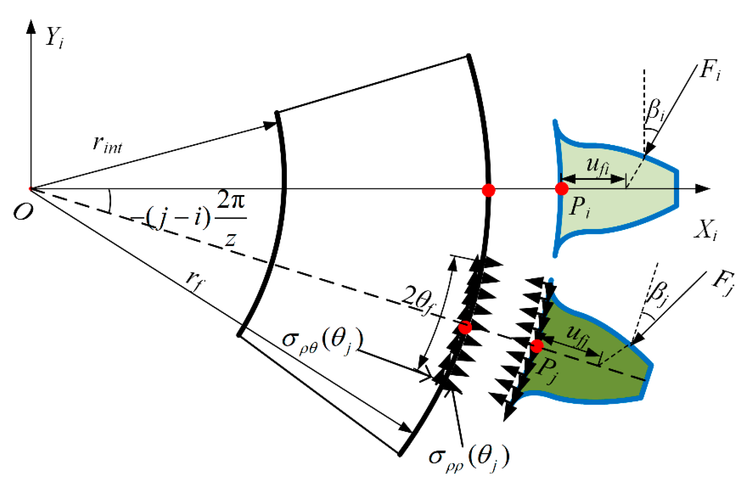
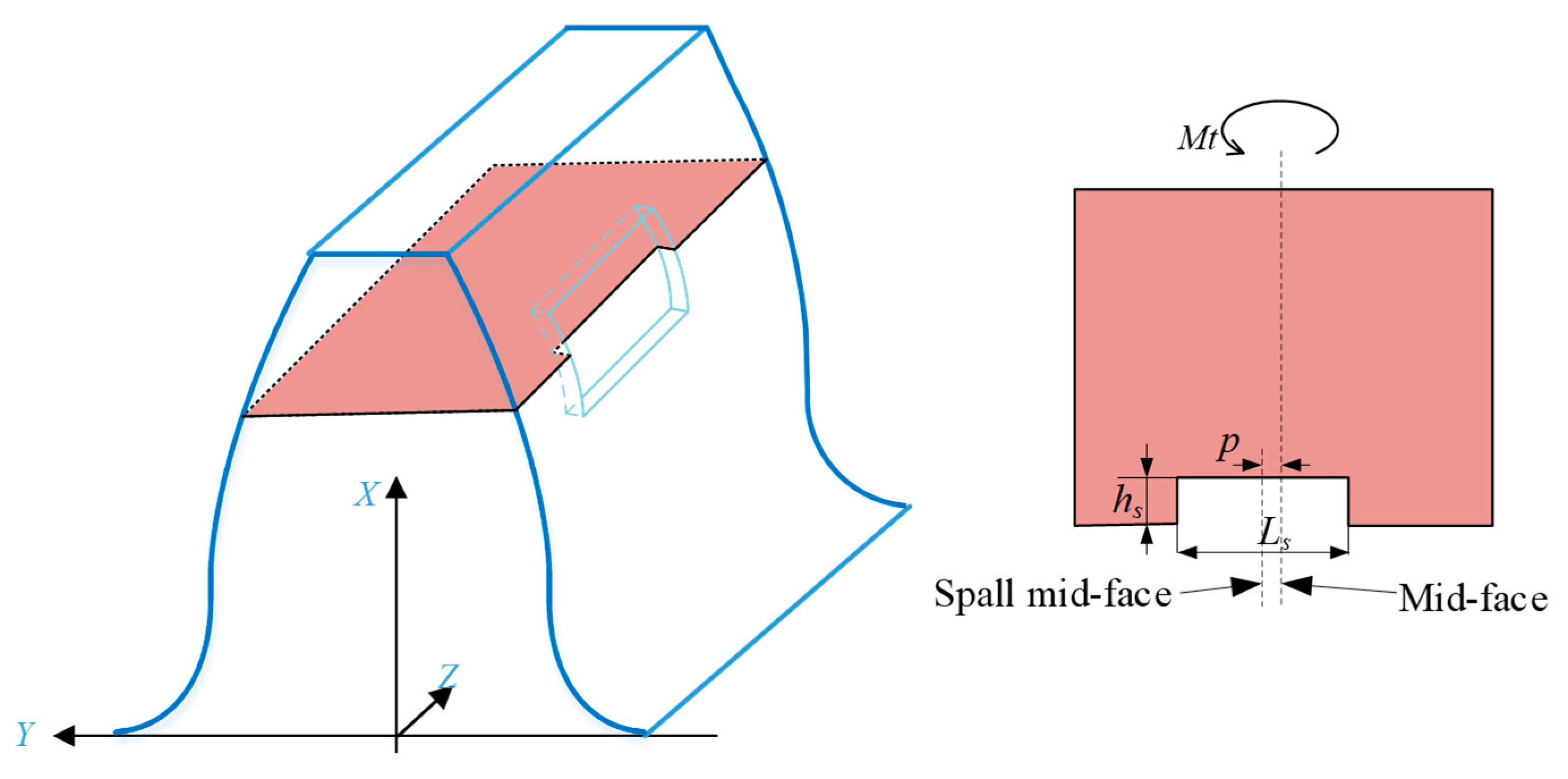
2. Improved TVMS Method for a Spalled Gear

As with healthy gear teeth, the TVMS of spalling teeth primarily comprises the Hertzian contact stiffness, kh, the gear tooth stiffness, kt, and the fillet foundation stiffness, kf [4].
k = 1 / i = 1 N 1 / k h i + 1 / k t i p + 1 / k t i g + 1 / k f i p + 1 / k f i g
Firstly, the Hertzian contact stiffness is calculated using a semi-empirical method [33]:
k h = E 0.9 L 0.8 F i 0.1 / 1.275 , non-spalling   areas E 0.9 ( L L s ) 0.8 F i 0.1 / 1.275 , spalling   areas
where Fi is the local meshing force between the i-th meshing tooth pair and E is Young’s modulus of the gear. L is the tooth width and Ls is the length of the spalling.
Due to the structural coupling effect of two meshing teeth in double-tooth engagement, the corresponding tooth fillet foundation stiffness is lower than the sum of those of two single-tooth pairs. Considering the structural coupling effect in double-tooth engagement, Muskhelishvili’s theory [34] regarding elastic rings was used to calculate the fillet foundation stiffness of the gear body. Figure 1 illustrates the deflection of tooth i caused by the gear body when tooth j is loaded. The tooth fillet foundation stiffness for the meshing tooth ii is derived as follows:
k f i = F i / ( δ f i j + δ f i i )
where δfij is the gear-body-induced deflection caused by the local meshing force Fj (j = 1, ⋯, N) in the direction of the local meshing force Fi. In double-tooth engagement situations (N = 2), because of the structural coupling effect, δfij(Ij) is not generally equal to zero, which indicates that the tooth fillet foundation stiffness is overestimated in the traditional method.
According to Ref. [35], the local gear-body-induced tooth deflections, denoted as δfii and δfjj, can be determined:
δ f i i = cos 2 β i E L L u f i S f 2 + M u f i S f + P 1 + Q tan 2 β i
δ f i j = F j cos β i cos β j E L L 1 u f i u f j S f 2 + M 1 tan β i + P 1 u f j S f + Q 1 tan β j + R 1 u f i S f + S 1 tan β j + T 1 tan β i + U 1 tan β j + V 1
where βi represents the pressure angle at the engagement point; ufi and ufj represent the distances between the intersection point of the effective tooth center line and the force action line and point Pi or Pj, respectively. The expression is ufi = rb/cosβirf (ufj = rb/cosβjrf).Sf = 2rf/θf. Here, rf is the radius of the root circle, and rint is the radius of the hub bore. For a detailed derivation of the terms L*, M*, P*, Q*, L1*, M1*, P1*, Q1*, R1*, S1*, T1*, U1*, and V1*, please refer to [35].
The bending stiffness kb, shear stiffness ks, and axial compression stiffness ka are standard components of the total gear tooth stiffness kt. The cantilever beam model of spalled teeth is illustrated in Figure 2. The angular displacement expression is employed to derive the tooth bending and shear and axial compression stiffnesses.
1 k s = π 2 α 0 f s G A x 1 d x 1 d γ d γ + τ B β f s G A x 2 d x 2 d τ d τ , τ B < β < τ C π 2 α 0 f s G A x 1 d x 1 d γ d γ + τ B τ C f s G A x 2 d x 2 d τ d τ + τ C β f s G A x 3 d x 2 d τ d τ , τ C < β < τ D π 2 α 0 f s G A x 1 d x 1 d γ d γ + τ B τ C f s G A x 2 d x 2 d τ d τ + τ C τ D f s G A x 3 d x 2 d τ d τ + τ D β f s G A x 4 d x 2 d τ d τ , τ D < β
1 k b = π 2 α 0 f b E I x 1 d x 1 d γ d γ + τ B β f b E I x 2 d x 2 d τ d τ , τ B < β < τ C π 2 α 0 f b E I x 1 d x 1 d γ d γ + τ B τ C f b E I x 2 d x 2 d τ d τ + τ C β f b E I x 3 d x 2 d τ d τ , τ C < β < τ D π 2 α 0 f b E I x 1 d x 1 d γ d γ + τ B τ C f b E I x 2 d x 2 d τ d τ + τ C τ D f b E I x 3 d x 2 d τ d τ + τ D β f b E I x 4 d x 2 d τ d τ , τ D < β
1 k a = π 2 α 0 f a E A x 1 d x 1 d γ d γ + τ B β f a E A x 2 d x 2 d τ d τ , τ B < β < τ C π 2 α 0 f a E A x 1 d x 1 d γ d γ + τ B τ C f a E A x 2 d x 2 d τ d τ + τ C β f a E A x 3 d x 2 d τ d τ , τ C < β < τ D π 2 α 0 f a E A x 1 d x 1 d γ d γ + τ B τ C f a E A x 2 d x 2 d τ d τ + τ C τ D f a E A x 3 d x 2 d τ d τ + τ D β f a E A x 4 d x 2 d τ d τ , τ D < β
where f s = 1.2 cos 2 β , f b = cos β x β x y β sin β 2 , and f a = sin 2 β . G = E/[2(1 + v)] indicates the shear modulus. ν denotes Poisson’s ratio. Ix1, Ix2, Ix3, and Ix4 denote the area moment of inertia, while Ax1, Ax2, Ax3, and Ax4 represent the cross-sectional areas within the segments AB, BC, CD, and DE. x1 and x2 denote the horizontal coordinates of the transition and involute curves, respectively. y1 and y2 denote the vertical coordinates of the transition and involute curves, respectively.
Not all spalls are aligned. Misaligned spalling defects lead to uneven load distributions on both sides of the gear’s central region. This uneven loading generates an additional torque, Mt, around the central axis, as shown in Figure 3, where Ls is the spalling length and hs is the spalling depth. In addition, p represents the offset distance from the spalling mid-face to the tooth mid-face. This is known as the torsional stiffness, kτ, which is a component of the tooth stiffness.
1 k τ = 0 , τ B < β < τ C & τ D < β π 2 α 0 L s p ( L L s ) 2 G I p t 1 d x 1 d γ d γ + τ B τ C L s p ( L L s ) 2 G I p t 2 d x 2 d τ d τ + τ C τ D L s p ( L L s ) 2 G I p t 3 d x 2 d τ d τ , τ C < β < τ D
where Ipt1, Ipt2, and Ipt3 represent the polar moments of inertia of the cross-sections in the transitional, healthy, and spalled parts, respectively.
To accommodate the various forms of spalling, defect ratios are employed during calculations [11,36].
C L s x = L s / L C h s x = h s / x 2 C p s x = p / L K c = 1 C h s x 5 C L s x 3 + ( 4 C h s x 2 6 C h s x 3 + 5 C h s x 4 ) C L s x 2 ( 5 C h s x + 4 C h s x 3 6 C h s x 2 ) C L s x ( 1 C h s x C L s x ) 2 K p = 1 + C h s x 2 C L s x 4 C h s x C L s x 3 ( 1 + 12 C p s x 2 ) C h s x C L s x 1 C h s x C L s x
where CLsx, Chsx, and Cpsx are the defect length ratio, defect depth ratio, and defect offset ratio of the tooth spall at displacement x, respectively.
From this, the expressions for Ix1, Ix2, Ix3, Ix4, Ax1, Ax2, Ax3, Ax4 Ipt1, Ipt2, and Ipt3 can be derived.
A x 1 = 2 y 1 L , A x 2 = 2 y 2 L , A x 3 = 2 ( 1 C h s x C L s x ) y 2 L , A x 4 = A x 2
I x 1 = 2 3 y 1 3 L , I x 2 = 2 3 y 2 3 L , I x 3 = 2 3 y 2 3 K c L , I x 4 = I x 2
I p t 1 = 2 y 1 L 12 4 y 1 2 + L 2 , I p t 2 = 2 y 2 L 12 4 y 2 2 + L 2 , I p t 3 = 1 6 K p y 2 L 3 + 2 3 K c y 2 3 L
Furthermore, due to the introduction of the defect ratio, the Hertzian contact stiffness can be corrected as follows:
k h = E 0.9 L 0.8 F i 0.1 / 1.275 , non-spalling   areas E 0.9 [ L ( 1 C L s x ) ] 0.8 F i 0.1 / 1.275 , spalling   areas
Finally, the TVMS of the spalled gear is given by the following:
k = 1 / i = 1 N 1 / k a i g + 1 / k b i g + 1 / k s i g + 1 / k τ i g + 1 / k f i g + 1 / k a i p + 1 / k b i p + 1 / k s i p + 1 / k τ i p + 1 / k f i p + 1 / k h i

3. Dynamic Modeling of Spur-Gear System

Figure 4 illustrates the dynamic model of the gear–rotor-bearing transmission system. This schematic depicts the gears, shafts, and bearings, highlighting the key characteristics resulting from gear meshing and bearing nonlinearity. Figure 5 shows the mechanical model of the gear system.
m 1 x ¨ 1 + c s 1 x ˙ 1 ξ 2 x ˙ b 1 ξ 1 x ˙ b 2 + k s 1 x 1 ξ 2 x b 1 ξ 1 x b 2 = m 1 ρ 1 θ ¨ 1 sin ω 1 t + θ 1 + ω 1 + θ ˙ 1 2 cos ω 1 t + θ 1 F f m 1 y ¨ 1 + c s 1 y ˙ 1 ξ 2 y ˙ b 1 ξ 1 y ˙ b 2 + k s 1 y 1 ξ 2 y b 1 ξ 1 y b 2 = m 1 ρ 1 ω 1 + θ ˙ 1 2 sin ω 1 t + θ 1 + θ ¨ 1 cos ω 1 t + θ 1 F m m 1 g J 1 + m 1 ρ 1 2 θ ¨ 1 + c t 1 θ ˙ 1 θ ˙ g + k t 1 θ 1 θ g = m 1 ρ 1 sin ω 1 t + θ 1 x ¨ 1 + cos ω 1 t + θ 1 y ¨ 1 F m r b 1 + T f 1
m 2 x ¨ 2 + c s 2 x ˙ 2 ξ 4 x ˙ b 3 ξ 3 x ˙ b 4 + k s 2 x 2 ξ 4 x b 3 ξ 3 x b 4 = m 2 ρ 2 θ ¨ 2 sin ω 2 t + θ 2 + ω 2 + θ ˙ 2 2 cos ω 2 t + θ 2 + F f m 2 y ¨ 2 + c s 2 y ˙ 2 ξ 4 y ˙ b 3 ξ 3 y ˙ b 4 + k s 2 y 2 ξ 4 y b 3 ξ 3 y b 4 = m 2 ρ 2 ω 2 + θ ˙ 2 2 sin ω 2 t + θ 2 θ ¨ 2 cos ω 2 t + θ 2 + F m m 2 g J 2 + m 2 ρ 2 2 θ ¨ 2 + c t 2 θ ˙ 2 θ ˙ p + k t 2 θ 2 θ p = m 2 ρ 2 sin ω 2 t + θ 2 x ¨ 2 cos ω 2 t + θ 2 y ¨ 2 + F m r b 2 T f 2
where xi, yi, and θi (i = 1, 2) represent the vibration displacements of the gears in the horizontal, vertical, and torsional directions, respectively. Ji (i = 1, 2) represents the moments of inertia about the center. The eccentricity of the driving and the driven gears are represented, respectively, by ρ1 and ρ2. kti and ksi (i = 1, 2) are the shaft’s torsional and transverse stiffness, respectively. cti and csi (i = 1, 2) are the corresponding damping coefficients, while g represents the acceleration of gravity. Tfi (i = 1, 2) represents the friction moment of the gear and pinion pairs; ωi (i = 1, 2) is the angular velocity of the gears; and t is the running time.
J g θ ¨ g + c t 1 θ ˙ g θ ˙ 1 + k t 1 θ g θ 1 = T g J p θ ¨ p + c t 2 θ ˙ p θ ˙ 2 + k t 2 θ p θ 2 = T p
where θg and θp are the vibration displacements in the torsional directions; Jg and Jp represent the moment of inertia of the input and output, respectively; and Tg and Tp denote the load torque.
m b 1 x ¨ b 1 + c s 1 ξ 2 x ˙ 1 + ξ 2 x ˙ b 1 + ξ 1 x ˙ b 2 + c x 1 x ˙ b 1 + k s 1 ξ 2 x 1 + ξ 2 x b 1 + ξ 1 x b 2 = 0 m b 1 y ¨ b 1 + c s 1 ξ 2 y ˙ 1 + ξ 2 y ˙ b 1 + ξ 1 y ˙ b 2 + c y 1 y ˙ b 1 + k s 1 ξ 2 y 1 + ξ 2 y b 1 + ξ 1 y b 2 = m b 1 g m b 2 x ¨ b 2 + c s 1 ξ 1 x ˙ 1 + ξ 2 x ˙ b 1 + ξ 1 x ˙ b 2 + c x 2 x ˙ b 2 + k s 1 ξ 1 x 1 + ξ 2 x b 1 + ξ 1 x b 2 = 0 m b 2 y ¨ b 2 + c s 1 ξ 1 y ˙ 1 + ξ 2 y ˙ b 1 + ξ 1 y ˙ b 2 + c y 2 y ˙ b 1 + k s 1 ξ 1 y 1 + ξ 2 y b 1 + ξ 1 y b 2 = m b 2 g m b 3 x ¨ b 3 + c s 2 ξ 4 x ˙ 2 + ξ 4 x ˙ b 3 + ξ 3 x ˙ b 4 + c x 3 x ˙ b 3 + k s 2 ξ 4 x 2 + ξ 4 x b 3 + ξ 3 x b 4 = 0 m b 3 y ¨ b 3 + c s 2 ξ 4 y ˙ 2 + ξ 4 y ˙ b 3 + ξ 3 y ˙ b 4 + c y 3 y ˙ b 3 + k s 2 ξ 4 y 2 + ξ 4 y b 3 + ξ 3 y b 4 = m b 3 g m b 4 x ¨ b 4 + c s 2 ξ 3 x ˙ 2 + ξ 4 x ˙ b 3 + ξ 3 x ˙ b 4 + c x 4 x ˙ b 4 + k s 2 ξ 3 x 2 + ξ 4 x b 3 + ξ 3 x b 4 = 0 m b 4 y ¨ b 4 + c s 2 ξ 3 y ˙ 2 + ξ 4 y ˙ b 3 + ξ 3 y ˙ b 4 + c y 4 y ˙ b 4 + k s 2 ξ 3 y 2 + ξ 4 y b 3 + ξ 3 y b 4 = m b 4 g
where mbi (i = 1, 2) is the mass of the bearings on the gear shaft; mbj (j = 3, 4) is the mass of the bearings on the pinion shaft. The support bearings are simplified as the radial stiffness and damping. kbxi, kbyi, cbxi, and cbyi (i = 1, 2, 3, 4) represent the stiffness and damping of the bearings in the x-direction and y-direction. ξ i (i = 1, 2, 3, 4) represents the deformation coefficient of the shafts, which is assumed to be zero.
δ = r b 1 ( ω 1 t + θ 1 ) r b 2 ( ω 2 t + θ 2 ) + y 1 y 2 + ρ 1 sin ( ω 1 t + θ 1 ) ρ 1 sin ( ω 2 t + θ 2 ) e t
where e(t) is a static transmission error caused by assembly and manufacture, whose expression can be given by e(t) = e0 + ersin(ωmt + φm), where e0 and er represent the meaning of the offset and amplitude of the error, respectively. ωm (ωm = 2πn1z1/60(2πn2z2/60)) and φm are, respectively, the mesh frequency and initial phase. z1 and z2 are the teeth of the driving and driven gears, respectively. Their rotational velocities are n1 and n2.
The dynamic mesh force Fm can be defined as follows:
F m = k f δ + c δ ˙
where k and c are the TVMS and mesh damping, respectively. f(δ) is the nonlinear function, which is defined as follows:
f ( δ ) = δ ( 1 ψ ) b , δ > b ψ b , b < δ < b δ + ( 1 ψ ) b , δ < b
where b is the gear backlash, while ψ is the coefficient of the function and set as 0 in this paper.
Friction always acts perpendicular to the line of engagement. When the point of engagement is at the knuckle line, the gears’ sliding speed is zero. As the meshing process continues, the relative velocity between the gears changes, causing the direction of the tooth friction to shift. Therefore, the direction of the coefficient of friction varies over time and can be expressed as follows:
s 1 = ( r b 1 + r b 2 ) tan α r a 2 2 r b 2 2 + r b 1 ω 1 t s 2 = r a 2 2 r b 2 2 + r b 1 ω 1 t λ = sgn ( ω 1 s 1 ω 2 s 2 ) F f = μ λ F m T f 1 = F f s 1 , T f 2 = F f s 2
where ra2 is the addendum ratio of the pinion, and λ is the friction direction coefficient. The friction coefficient is μ, and its value is 0.1 in this paper.

4. Results and Discussion

4.1. Model Validation

The finite element method (FEM) is a well-established and widely used technique for calculating the TVMS of spur-gear systems. Results obtained based on the FEM are commonly employed to validate the TVMS values derived from energy methods. In this section, a pair of spur gears is used as a case study to compare the TVMS values of two adjacent spalled teeth on the driving gear and to validate the model using both our proposed MATLAB R2022b-based method and an ANSYS 2023R1-based FEM. The detailed parameters for the spur-gear pair are presented in Table 1, and the simplified model of the adjacent spalling teeth is illustrated in Figure 6.
To reduce computation time, the finite element model of each gear contains five teeth, where two adjacent teeth of the driving gear have spalls. All degrees of freedom of the controller node of the driven gear are constrained, as are the translational degrees of freedom of the driving gear bore node. The angular displacement of the driving gear is derived from static analysis. The TVMS is determined as follows [37]:
k = T / Δ θ r b 1 2
where T is the torque on the driving gear, rb1 is the base circle radius of the driving gear, and Δθ is the angle displacement of the driving gear. However, it is important to note that meshing methods may fail to accurately capture the TVMS in extreme spalling scenarios. Mesh-free methods, such as the one proposed by Xia [38], could represent a promising direction for the study of extreme failures.
In the gear set, spalling occurs to different extents on two adjacent teeth of the driving gear, while the other teeth remain unaffected. To facilitate our analysis, the initial spalling failure is labeled spalling 1, and the subsequent failure is labeled spalling 2. Spalling 1 has the parameters of Ls1 = 6 mm and ρ1 = 4 mm, starting at 59 mm from the root on the tooth face and ending at 61 mm. Spalling 2 has the parameters of Ls2 = 4 mm and ρ2 = 2 mm, starting at 59.5 mm from the root on the tooth face and ending at 60.5 mm.
Figure 7 presents the TVMS results for the adjacent spalled teeth based on the proposed analytical method and the FEM. In the first engagement cycle, the TVMS decreases significantly as spalling 1 occurs. The decrease in TVMS is further amplified in the second engagement cycle due to the simultaneous engagement of two spalling teeth. By the third meshing cycle, the change in TVMS is primarily influenced by spalling 2. The results from the proposed method align well with the FEM when modeling spalling failure, further validating the reliability and effectiveness of the proposed method.

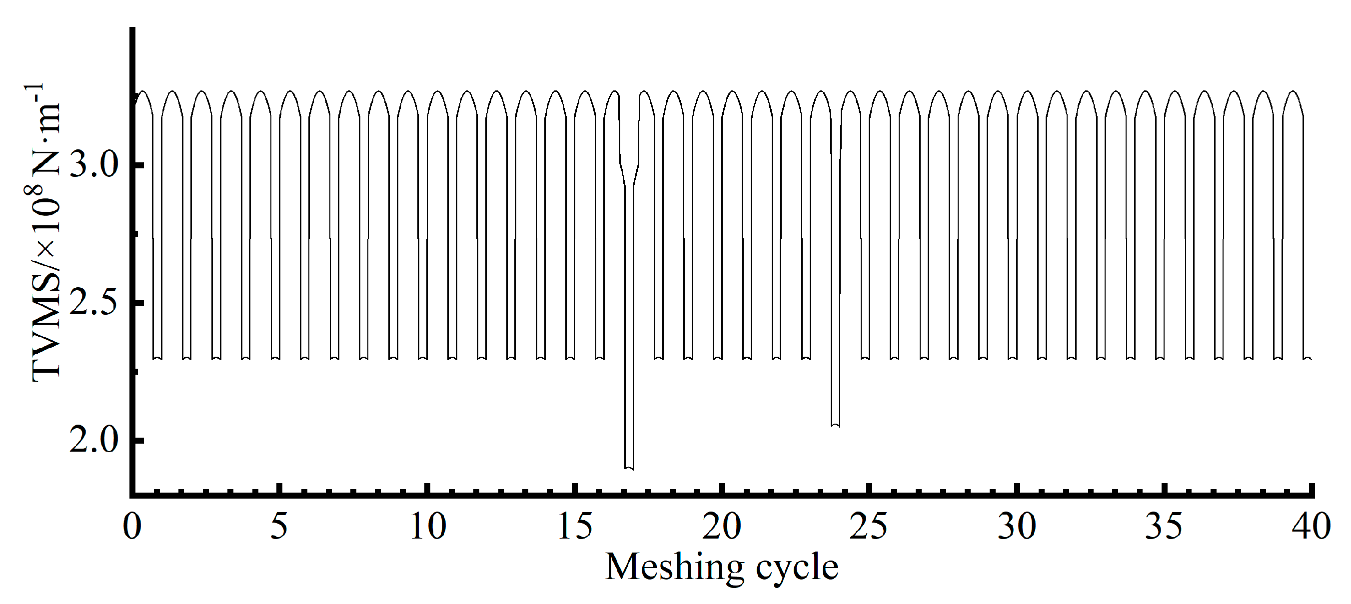
4.2. Multi-Spalling TVMS Calculation

In addition to the previously calculated TVMS for adjacent spalling teeth, three cases of multi-spalling in a spur gearbox for evaluating the TVMS in a gear set are considered. These cases include multi-spalling on the same tooth within a gear, on non-adjacent teeth within the same gear, and on different gears. The following sections provide a detailed analysis of each of these cases.

4.2.1. Multi-Spalling on Non-Adjacent Teeth Within a Gear

In the gear set, varying degrees of spalling are introduced on two non-adjacent teeth of the driving gear, while the remaining teeth remain undamaged. The parameters for the first spalling are Ls1 = 6 mm and ρ1 = 3 mm, starting 60 mm from the root on the tooth face and extending to 61 mm. The second spalling is characterized by Ls2 = 4 mm and ρ2 = 2 mm, starting at 59 mm from the root on the tooth face and extending to 60.5 mm. The depth of all spalled areas is 0.9 mm. Because the spalling fault affects two non-adjacent gear tooth surfaces, analyzing both the contact and non-contact meshing cycles throughout the entire meshing process is crucial. Figure 8 illustrates the calculated TVMS for this case. The result indicates that when a spalling fault occurs on the gear surface, the TVMS significantly decreases during the 16th and 22nd meshing cycles involving the faulted area. The two spalling faults, with different parameters, have distinct effects on the TVMS. The first spalling causes a more significant decrease in TVMS than the second. Once the faulty region disengages from the meshing process, the gear stiffness is restored to its healthy state.

4.2.2. Multi-Spalling on the Same Tooth Within a Gear

In a gear set, varying degrees of spalling occur on a single tooth of the driving gear, while the remaining teeth stay undamaged. The parameters for the first spalling are Ls1 = 6 mm and ρ1 = 4 mm, with the spalling area beginning at 59.5 mm from the tooth face and extending to 61 mm. The parameters for the second spalling are Ls2 = 4 mm and ρ2 = 2 mm, with the spalling area beginning at 59 mm from the tooth face and extending to 60.5 mm. The depth of all spalls is 0.9 mm. The TVMS is significantly reduced when spalling occurs during the gear meshing, as shown in Figure 9.
The TVMS is significantly reduced during the meshing process when spalling faults occur. Spalling failure, particularly asymmetric spalling, leads to a change in the torsional stiffness of the gear. The TVMS value is lower when considering the asymmetric spalling torsional effect than when this effect is ignored. When two spalls are implanted on the same side, a partial overlap occurs due to the parameter settings. The implantation on both sides does not cause this overlap, but it does explain the significant change in TVMS during single-tooth engagement. Two spalling regions are involved during meshing within the range of 59.5 mm to 60.5 mm from the tooth root. At this point, the parameters of these regions must be reassessed to evaluate their effect on contact stresses and gear performance. Once the two spalled regions are disengaged, the gear stiffness returns to a healthy state, and the contact stress normalizes.

4.2.3. Multi-Spalling on Different Gears

When both the driving and driven gears experience spalling faults, the period of TVMS variation corresponds to the least common multiple of the number of their teeth. In this case, the period of variation is determined by the number of their teeth, which is 40 meshing cycles, as both gears have the same number of teeth. This means that even if both gears experience spalling faults simultaneously, the periodic component of TVMS variation is limited by the number of teeth, thus restricting the extracted variation. To explore the possible variations, this section excludes specific practical scenarios and focuses on the variation in TVMS components that are caused by spalling faults. While this simplifying assumption aids the analysis, it also has some limitations.
Additionally, the spalling parameters for the master gear are Ls1 = 5 mm and ρ1 = 3 mm, ranging from 59 mm at the tooth face to the root and ending at 60 mm. The spalling parameters for the driven gear are Ls2 = 4 mm and ρ2 = 2 mm, ranging from 59 mm at the tooth face to the root and ending at 60.5 mm. All spalling faults have a depth of 0.9 mm.
Typically, a TVMS change cycle consists of eight stiffness components: Hg-Hp-Hg-Hp, Sg-Sp-Hg-Hp, Hg-Sp-Hp-Hg, Sg-Hp-Hg-Hp, Sg-Hp-Hg-Sp, Hg-Sp-Sg-Hp, Sg-Hp-Hg-Hp-Hg-Sp, and Hg-Sp-Hg-Hp-Sg-Hp. The uppercase letters represent the condition of the gear teeth: “S” denotes spalling teeth, while “H” represents healthy teeth. The lowercase letters refer to the gears in which these teeth are located, such as “p” for the pinion and “g” for the gear.
For example, “Hg-Hp” indicates a healthy tooth on the gear mesh with a healthy tooth on the pinion; “Sg-Hp” signifies a spalling tooth on the gear mesh with a healthy teeth on the pinion; “Hg-Sp” represents a healthy tooth on the gear mesh with a spalling tooth on the pinion; and “Sg-Sp” indicates a spalling tooth on the gear mesh with a spalling tooth on the pinion. These symbols represent the sequence of meshing. For instance, “Sg-Sp-Hg-Hp” indicates that the spalling teeth on both gears mesh first, followed by the engagement of the two healthy teeth. The TVMS values resulting from these engagement cases are shown in Figure 10. The TVMS for Hg-Hp-Hg-Hp, Sg-Sp-Hg-Hp, Hg-Hp-Hg-Sp, and Hg-Hp-Sg-Hp lasts for two engagement cycles, or [0, 4π/40] rad. Those for Sg-Hp-Hg-Sp and Hg-Sp-Sg-Hp last for three engagement cycles, or [0, 6π/40] rad, while those for Sg-Hp-Hg-Hp-Hg-Sp and Hg-Sp-Hg-Hp-Hg-Hp last for four engagement cycles, or [0, 8π/40] rad.
In the case of reciprocal tooth numbers, TVMS will occur only once for certain engagement cases. For instance, engagement patterns such as Sg-Sp-Hg-Hp, Sg-Hp-Hg-Sp, Hg-Sp-Sg-Hp, Sg-Hp-Hg-Hp-Hg-Sp, and Hg-Sp-Hg-Hp-Sg-Hp result in TVMS occurring only once. The occurrences of Hg-Hp-Hg-Sp are equal to the number of teeth on the master gear minus five (five appeals), while for Hg-Hp-Sg-Hp, it occurs as many times as the number of teeth on the driven gear minus five. All other stiffness components, except for these engagement cases, follow the pattern of Hg-Hp-Hg-Hp.

4.3. Dynamic Simulation Analysis and Experimental Verification

This section compares the simulation vibration response with the experimental results to validate the accuracy of the dynamic multi-spalling spur-gear model. Experimental verification is conducted for multi-spalling on adjacent teeth of the driving gear and for tooth spalling on different gears.

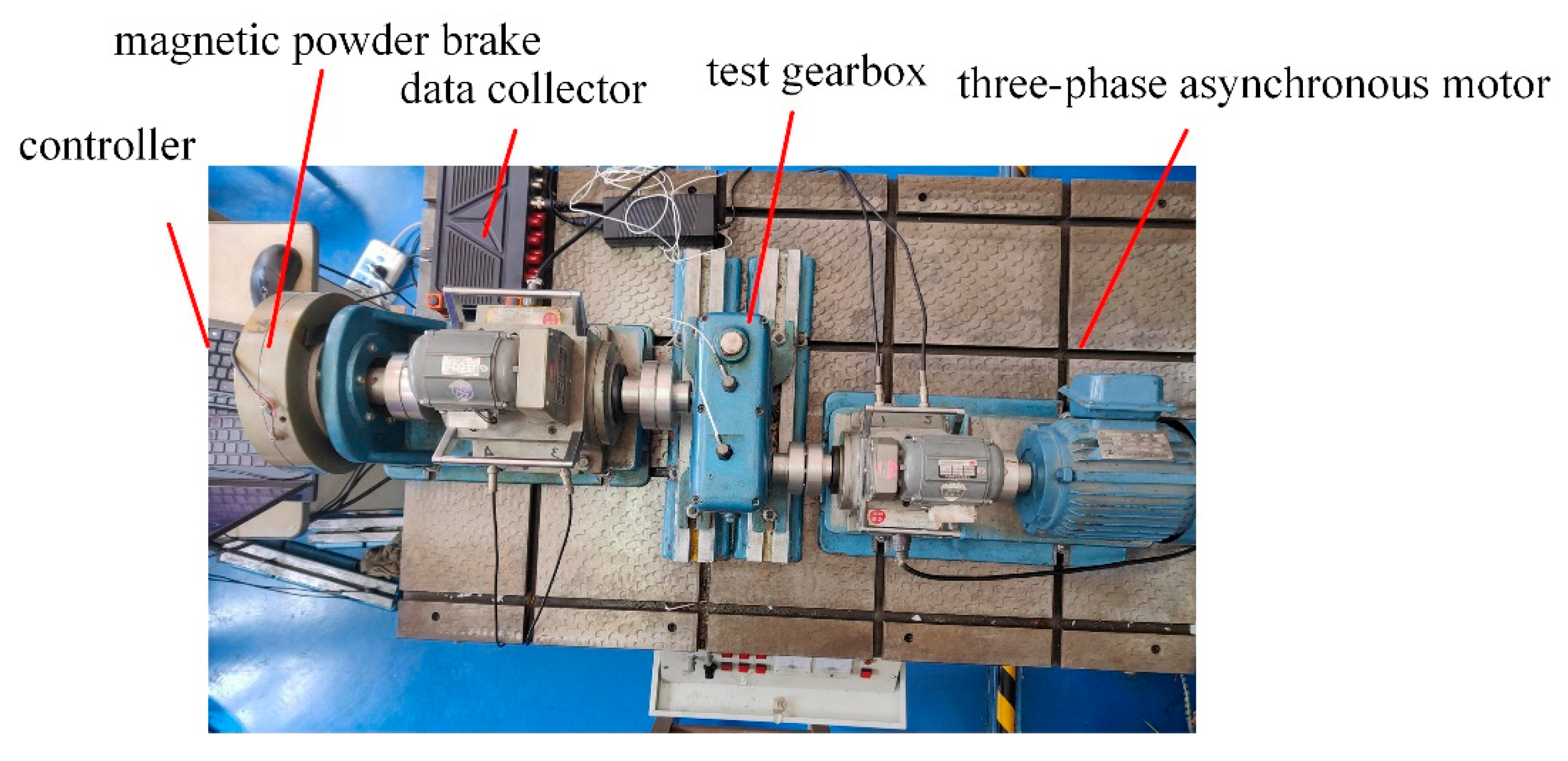
4.3.1. Experimental Equipment

This section compares the simulated vibration response with the experimental vibration response to validate the dynamic model of a spur-gear system with tooth spalls. As shown in Figure 11, the gear failure test bench consists of a controller, a three-phase asynchronous motor, a test gearbox, and a magnetic powder brake. We collected data using a DYTRAN-305501 (Dytran Instruments, Chatsworth, CA, USA), and acceleration sensors were used to measure the vibration acceleration in the vertical direction of the gearbox. The sampling time was 10 s, with a 0.2 segment being chosen for comparison with the simulation. The input speed of the three-phase asynchronous motor was 1000 r/min. According to the gear parameters in Table 2, the rotational frequency of the driving gear is fs = 1000/60 = 16.67 Hz, and the meshing frequency is fm = z1 fs = 433.3 Hz. The rotational and meshing periods of the gear system are Ts = 0.06 s and Tm = 0.0023 s, respectively.
Two sets of faulty gears were used for the dynamics analysis based on the multi-spalling scenarios described above: one with multi-spalling on adjacent gears and the other with spalling on two gears. Multi-tooth spalling faults were artificially introduced to simulate the behavior of spur gears, and real spalling situations were considered. In addition, the gear material was carbon steel.

4.3.2. Multi-Spalling on Adjacent Teeth of the Driving Gear

The cases of spalling on adjacent teeth and multiple instances of spalling on the same tooth within a gear will be analyzed together, as shown in Figure 12. Three consecutive teeth exhibit tooth spalls (marked from right to left as spalling teeth 1, 2, and 3). There are two spalls on spalling tooth 1, while spalling teeth 2 and 3 have one spalling each. In addition to the experimental spalling, the spalling parameters shown in Table 3 are used. Based on the literature, we can obtain the parameter calculation formula for tooth spalls in a round shape based on the method described in ref. [36]:
L s = l max 2 ( 1 4 ( x c e n t e r x ) 2 w max 2 cos 2 θ s
where xs_st = xcenterwmaxcosθs/2 is the starting position of the tooth spall, while θs defines the inclination of the spall. xs_end = xcenter +wmaxcosθs/2 is the end position of the spall. When lmax = wmax, the tooth spall has a round shape. The parameters in Table 3 can be used to calculate the necessary cross-sectional characteristics of TVMS for elliptical spalling.
As shown in Figure 13, the TVMS of the spur-gear pair significantly decreases when contact occurs in the spalling failure region. In this case, spalling of multiple teeth occurs, resulting in a significant impulse phenomenon in the displacement response. Specifically, three impulse pulses appear in the displacement response due to spalling on three neighboring teeth. However, when the three impulses coincide, their individual effects are not prominent, which is closely related to the specific parameters of the spalling teeth. Further analysis reveals that the effect of spalling tooth 1 is the most significant due to two spalls, while tooth 2 has a moderate effect, and tooth 3’s effect is relatively small. This is mainly due to its small spall area and location further from the tooth root, which limits its effect on the system. These differences indicate that the spalling area, location, and degree of tooth surface damage directly affect the intensity of the effect and its effect on the system’s dynamic behavior.
The interval between the consecutive effects is 0.0023 s, coinciding with the meshing period of one tooth in the gear. This regularity provides a valuable reference for further analysis. The system will experience three consecutive impulses after a 0.06-second interval, coinciding with the gear’s rotation period. This suggests that the impulses from the spalled teeth will alternate during gear rotation, causing a periodic vibration response. The effect of spalling is especially significant when two spalled teeth are adjacent.
Further analysis of the FFT spectrogram shows that it primarily consists of the mesh frequency fm (433.3 Hz) and other frequency components. These result from the modulation between the rotational and engagement frequencies, and their presence often indicates a malfunction. Each frequency peak is accompanied by multiple sidebands, which arise from the nonlinear characteristics of the gear system and the effect of multi-tooth spalling. Figure 14 shows the experimental acceleration waveforms and FFT spectra. When a spalling fault occurs, the acceleration response shows a precise periodic pulse with an interval of approximately 0.06 s, corresponding to the rotational period of the driving gear, Ts. This observation aligns with our simulation analysis, confirming the reliability and accuracy of the simulation model. By comparing Figure 13 and Figure 14, we can see that the mesh frequency peaks in the FFT spectrum are prominent and easily recognizable in both the experimental data and simulation results. Although there is some discrepancy between the experimental and simulation results, the magnitude remains within acceptable limits and does not exceed the experimental tolerance. A comparison of the two spectra confirms the consistency between the experimental and simulation results regarding dynamic response characteristics, further strengthening the validity and accuracy of our analysis method. Additionally, repeated comparisons of the experiment and simulation verify the broad applicability and accuracy of the proposed method in gear fault diagnosis, providing a reliable theoretical basis and practical support for gear health monitoring.

4.3.3. Multi-Spalling on Different Gears

This study considers two cases: multi-spalling on different gears and multi-spalling on non-adjacent teeth. The driving gear spalls at tooths 1 and 14, while the spalling occurs at tooth 7. These three spalls match the parameters of spalling 1 in Table 3 and exhibit similar characteristics. To comprehensively analyze the system’s dynamic response, the periodic effects of these spalled teeth must be examined in detail. In this section, as the gear teeth are mutually healthy, the period of change is the product of their tooth numbers, i.e., 26 × 31 meshing cycles. Therefore, the meshing time for one cycle is 31 × 0.06 s. This periodic variation dictates the vibration characteristics during the meshing cycle of the gears, reflecting interactions between the different spalled teeth. When both gears are spalled, their meshing process is affected by local damage and the variation in the meshing combination of gear teeth caused by the spalled areas. This, in turn, leads to changes in the system’s overall vibration characteristics. In this case, the frequency components of the vibration response increase and become more complex. As shown in Figure 15, during the 26 × 31 meshing cycles, the eight previously mentioned TVMS components interact, resulting in a multi-frequency vibration pattern in the system. These multi-frequency components emerge from the meshing of different spalling teeth, and their interaction causes frequency mixing.
The FFT image demonstrates that when both gears experience spalling simultaneously, the turn and meshing frequencies are also visible, in addition to the peaks. The failure of the 1st and 14th teeth on the driving gear, which has 26 teeth, results in a signal at twice the rotational frequency. Additionally, the rotational frequency component of the driven wheel appears, which would not be observed if the driven wheel was functioning normally. The experimental FFT images display both frequency components. The simulation analysis aligns closely with the experimental results, confirming the model’s reliability and accuracy. Comparing Figure 15 and Figure 16, the experimental data and simulation results show prominent peaks at grid frequencies in the FFT spectrum, which are easily identifiable. The long experimental duration and increased impulses result in more chaotic acceleration signals; however, the overall curves remain similar, with the difference falling within an acceptable range.
The effect of varying spalling degrees on the system’s response is analyzed through comparison to verify the correlation between the experimental and simulation results. Under multi-tooth spalling, the system’s dynamic behavior is influenced by both individual spalling teeth and the combined effects of the distribution and degree of spalling. For instance, when more teeth are spalled, the system exhibits more complex vibration characteristics, making nonlinear behaviors more pronounced. Analyzing the vibration response of spalled teeth in both the time and frequency domains helps identify nonlinear vibration patterns, effectively revealing the effect of spalling faults on the system.

5. Conclusions

Most studies on spalling focus on single or symmetric types, often overlooking the torsional effects that are caused by asymmetric or multiple spalling failures. A shape-independent TVMS model for spalled gears, which accounts for torsional stiffness, was proposed and validated using finite element analysis. Various forms of multi-spalling TVMS scenarios were analyzed. A 16-degree-of-freedom dynamics model was developed, and corresponding experiments were designed to validate the model. The main conclusions are as follows:
(1)
The proposed method can accurately calculate the TVMS of multi-spalling gears. Compared with traditional methods, it offers superior accuracy and greater generality. Therefore, the method shows strong potential for application in gear fault diagnosis.
(2)
When two adjacent teeth are spalled, the TVMS experiences a significant reduction. Asymmetric spalling causes a more substantial decrease in TVMS than symmetric spalling, even when the parameters are the same. The effect of multiple spalling teeth on the TVMS depends on the specific spalling parameters. Additionally, spalling on different gears results in eight distinct stiffness components.
(3)
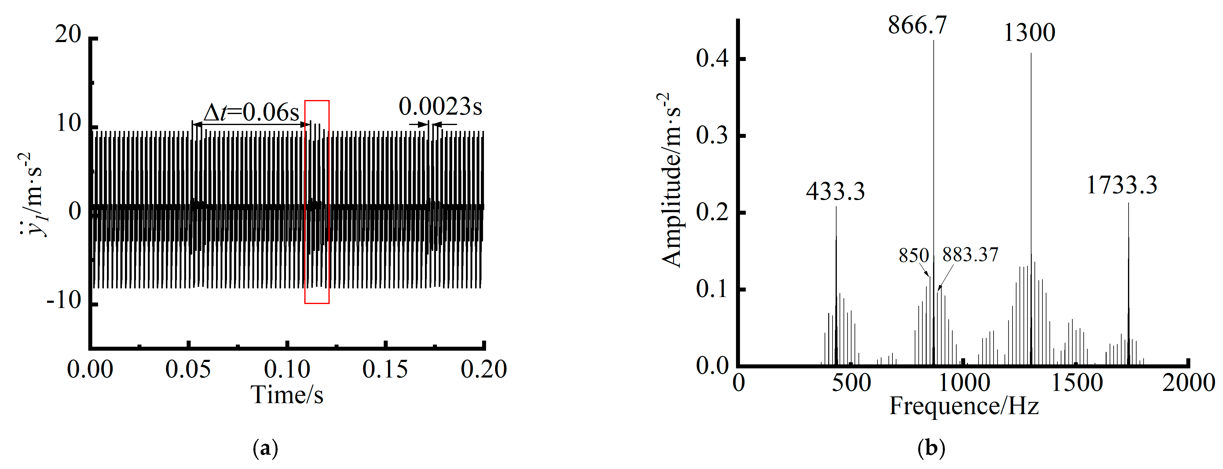
The dynamic behavior of a multi-spalling gear system is influenced not only by individual spalling teeth but also by the combined effects of the distribution and degree of spalling. Different spalling modes can significantly change the system’s dynamic behavior. When teeth with spalling faults mesh, the vibration response exhibits more pronounced shocks. The FFT spectrum of the gear system modulates the meshing frequency, incorporating the corresponding rotational frequencies of gears with spalling faults. This study provides a solid foundation for understanding the dynamic behavior of spalled gear systems, revealing their dynamic characteristics and failure mechanisms.
However, this study has some limitations. The method does not account for the effects of temperature and high-load conditions on gear performance, which could affect its applicability under extreme operating scenarios. Additionally, the dynamic model overlooks the effects of time-varying friction, lubrication, temperature, and bearing forces.

Author Contributions

Conceptualization, X.K. and Y.Y.; methodology, X.K.; software, Y.Y.; validation, Y.Y., S.S. and Y.X.; formal analysis, Y.Y.; investigation, Y.Y.; resources, Q.M.; data curation, Y.Y.; writing—original draft preparation, Y.Y.; writing—review and editing, Y.Y.; visualization, Y.Y.; supervision, Y.Y.; project administration, X.K.; funding acquisition, X.K. All authors have read and agreed to the published version of the manuscript.

Funding

This work was funded by the National Natural Science Foundation of China, grant number 52475113, and the Liaoning Provincial Science and Technology Program Joint Program (Applied Basic Research Project), grant number 2023JH2/101700270.

Data Availability Statement

Data are contained within the article.

Conflicts of Interest

The authors declare no conflicts of interest.

Abbreviations

The following abbreviations are used in this manuscript:
DOFsdegrees of freedom
TVMStime-varying meshing stiffness
FEMfinite element method
Hg-Hphealthy tooth on the gear mesh with healthy tooth on the pinion
Sg-Hpspalling tooth on the gear mesh with healthy tooth on the pinion
Hg-Sphealthy tooth on the gear mesh with spalling tooth on the pinion
Sg-Spspalling tooth on the gear mesh with spalling tooth on the pinion

References

  1. Liang, X.; Zhang, H.; Zuo, M.J.; Qin, Y. Three new models for evaluation of standard involute spur gear mesh stiffness. Mech. Syst. Signal Process. 2018, 101, 424–434. [Google Scholar] [CrossRef]
  2. Chen, Z.; Zhai, W.; Wang, K. Dynamic investigation of a locomotive with effect of gear transmissions under tractive conditions. J. Sound. Vib. 2017, 408, 220–233. [Google Scholar] [CrossRef]
  3. Saxena, A.; Parey, A.; Chouksey, M. Time varying mesh stiffness calculation of spur gear pair considering sliding friction and spalling defects. Eng. Fail. Anal. 2016, 70, 200–211. [Google Scholar] [CrossRef]
  4. Ma, H.; Li, Z.; Feng, M.; Feng, R.; Wen, B. Time-varying mesh stiffness calculation of spur gears with spalling defect. Eng. Fail. Anal. 2016, 66, 166–176. [Google Scholar] [CrossRef]
  5. Luo, Y.; Baddour, N.; Han, G.; Jiang, F.; Liang, M. Evaluation of the time-varying mesh stiffness for gears with tooth spalls with curved-bottom features. Eng. Fail. Anal. 2018, 92, 430–442. [Google Scholar] [CrossRef]
  6. Luo, W.; Qiao, B.; Zhixian, S.; Yang, Z.; Chen, X. Time-varying mesh stiffness calculation of a planetary gear set with the spalling defect under sliding friction. Meccanica 2020, 55, 245–260. [Google Scholar] [CrossRef]
  7. Cheng, Z.; Huang, K.; Xiong, Y.; Han, G. An improved model for dynamic characteristics analysis of high-contact-ratio spur gears considering localised tooth spall defect. Eng. Fail. Anal. 2022, 140, 106600. [Google Scholar] [CrossRef]
  8. Wu, X.; Luo, Y.; Li, Q.; Shi, J. A new analytical model for evaluating the time-varying mesh stiffness of helical gears in healthy and spalling cases. Eng. Fail. Anal. 2022, 131, 105842. [Google Scholar] [CrossRef]
  9. Li, Z.; Zhang, J.; Song, H.; Zhu, R.; Ma, H. Time-varying mesh stiffness calculation of spiral bevel gear with spalling defect. Mech. Mach. Theory 2024, 193, 105571. [Google Scholar] [CrossRef]
  10. Hou, J.; Yang, S.; Li, Q.; Liu, Y. Effect of a Novel Tooth Pitting Model on Mesh Stiffness and Vibration Response of Spur Gears. Mathematics 2022, 10, 471. [Google Scholar] [CrossRef]
  11. Jin, Y.; Zhang, Q.; Chen, Y.; Zu, T. A shape-independent analytical method for gear mesh stiffness with asymmetric spalling defects. Sci. Rep. 2024, 14, 15545. [Google Scholar] [CrossRef]
  12. Xiao, H.; Zhang, F.; Gao, J.; Li, Z. Improved mesh stiffness model of spur gear considering spalling defect influenced by surface roughness under EHL condition. Mech. Based Des. Struct. Mach. 2024, 52, 8865–8889. [Google Scholar] [CrossRef]
  13. Lu, Z.; Chen, Y.; Zu, T.; Zhang, W. A spalling evolution model for time-varying mesh stiffness evaluation and service life prediction of gears. Mech. Syst. Signal Process. 2023, 193, 110227. [Google Scholar] [CrossRef]
  14. Han, L.; Qi, H. Influences of tooth spalling or local breakage on time-varying mesh stiffness of helical gears. Eng. Fail. Anal. 2017, 79, 75–88. [Google Scholar] [CrossRef]
  15. Wang, S.; Zhu, R. An improved mesh stiffness model for double-helical gear pair with spalling defects considering time-varying friction coefficient under mixed EHL. Eng. Fail. Anal. 2021, 121, 105174. [Google Scholar] [CrossRef]
  16. Zhang, Y.; Liu, W.; Song, C.; Lin, T.; Duan, M. Analysis of time-varying meshing stiffness of helical gear pair with tooth surface spalling. J. Phys. Conf. Ser. 2021, 1820, 012131. [Google Scholar] [CrossRef]
  17. Luo, Y.; Baddour, N.; Liang, M. Dynamical modeling and experimental validation for tooth pitting and spalling in spur gears. Mech. Syst. Signal Process. 2019, 119, 155–181. [Google Scholar] [CrossRef]
  18. Yang, L.; Chen, Q.; Yin, L.; Wang, L.; Shao, Y. Dynamic characteristic of spur gear system with spalling fault considering tooth pitch error. Qual. Reliab. Eng. Int. 2022, 38, 2921–2938. [Google Scholar] [CrossRef]
  19. Wang, L.; Deng, C.; Xu, J.; Yin, L.; Yu, W.; Ding, X.; Shao, Y.; Huang, W.; Yang, X. Effects of spalling fault on dynamic responses of gear system considering three-dimensional line contact elasto-hydrodynamic lubrication. Eng. Fail. Anal. 2022, 132, 105930. [Google Scholar] [CrossRef]
  20. Huangfu, Y.; Chen, K.; Ma, H.; Li, X.; Han, H.; Zhao, Z. Meshing and dynamic characteristics analysis of spalled gear systems: A theoretical and experimental study. Mech. Syst. Signal Process. 2020, 139, 106640. [Google Scholar] [CrossRef]
  21. Shi, L.; Wen, J.; Pan, B.; Xiang, Y.; Zhang, Q.; Lin, C. Dynamic Characteristics of a Gear System with Double-Teeth Spalling Fault and Its Fault Feature Analysis. Appl. Sci. 2020, 10, 7058. [Google Scholar] [CrossRef]
  22. Wu, J.; Yang, Y.; Cheng, J. A novel estimation method of friction coefficient for evaluating gear pitting fault. Eng. Fail. Anal. 2021, 129, 105715. [Google Scholar] [CrossRef]
  23. Liu, Z.; Shang, E.; Huangfu, Y.; Ma, H.; Zhu, J.; Zhao, S.; Long, X.; Li, Z. Vibration characteristics analysis of flexible helical gear system with multi-tooth spalling fault: Simulation and experimental study. Mech. Syst. Signal Process. 2023, 201, 110687. [Google Scholar] [CrossRef]
  24. Xiang, L.; An, C.; Zhang, Y.; Hu, A. Failure dynamic modelling and analysis of planetary gearbox considering gear tooth spalling. Eng. Fail. Anal. 2021, 125, 105444. [Google Scholar] [CrossRef]
  25. Luo, W.; Qiao, B.; Shen, Z.; Yang, Z.; Cao, H.; Chen, X. Investigation on the influence of spalling defects on the dynamic performance of planetary gear sets with sliding friction. Tribol. Int. 2021, 154, 106639. [Google Scholar] [CrossRef]
  26. Sun, Z.; Tang, J.; Chen, S.; Li, H.; Tao, X.; Hu, Z. Dynamical modeling and characteristics analysis of tooth spalling in gear system with weight reduction structure. Mech. Mach. Theory 2023, 189, 105429. [Google Scholar] [CrossRef]
  27. Luo, Y.; Wang, H.; Shi, J.; Yang, S.; Baddour, N.; Liang, M. Fault feature analysis and detection of progressive localized gear tooth pitting and spalling. Meas. Sci. Technol. 2022, 33, 115002. [Google Scholar] [CrossRef]
  28. Bai, W.; Zhou, X.; Wang, Y.; Zeng, Q.; Zhan, S.; Hua, X.; Bao, G. Vibration Analysis of the Electric Drive System with Inter-turn Short-Circuit and Gear Spalling Faults. J. Vib. Eng. Technol. 2023, 11, 3595–3605. [Google Scholar] [CrossRef]
  29. Dai, P.; Lu, J.; Liang, X.; Wang, J.; Wang, F. Dynamic behavior analysis for cages in gear-bearing system with spalling failure on tooth surface. Eng. Fail. Anal. 2023, 154, 107657. [Google Scholar] [CrossRef]
  30. Zhang, X.; Li, H.W.; Li, Q.; Niu, X.J.; Li, W. Dynamic Characteristics Analysis of High-Speed Fixed-Axis Gear Pair with Spalling Fault for a Wind Turbine Gearbox Considering Friction and Flash Temperature. Mech. Solids 2024, 59, 1154–1179. [Google Scholar] [CrossRef]
  31. Yan, S.; Dai, P.; Shu, D.; Wang, J.; Wei, S.; Liu, P.; Zhang, D.; Li, H. Deformation and Response Analysis of Spur Gear Pairs with Flexible Ring Gears and Localized Spalling Faults. Machines 2022, 10, 560. [Google Scholar] [CrossRef]
  32. Liang, X.-H.; Liu, Z.-L.; Pan, J.; Zuo, M.J. Spur Gear Tooth Pitting Propagation Assessment Using Model-based Analysis. Chin. J. Mech. Eng. 2017, 30, 1369–1382. [Google Scholar] [CrossRef]
  33. Tavakoli, M.S.; Houser, D.R. Optimum profile modifications for the minimization of static transmission errors of spur gears. J. Mech. Transm. Autom. Des. 1986, 108, 86–94. [Google Scholar] [CrossRef]
  34. Muskhelishvili, N.I. Some Basic Problems of the Mathematical Theory of Elasticity; Springer: Dordrecht, The Nederlands, 1977. [Google Scholar]
  35. Xie, C.; Hua, L.; Han, X.; Lan, J.; Wan, X.; Xiong, X. Analytical formulas for gear body-induced tooth deflections of spur gears considering structure coupling effect. Int. J. Mech. Sci. 2018, 148, 174–190. [Google Scholar] [CrossRef]
  36. Luo, Y.; Baddour, N.; Liang, M. A shape-independent approach to modelling gear tooth spalls for time varying mesh stiffness evaluation of a spur gear pair. Mech. Syst. Signal Process. 2019, 120, 836–852. [Google Scholar] [CrossRef]
  37. Wang, Q.; Chen, K.; Zhao, B.; Ma, H.; Kong, X. An analytical-finite-element method for calculating mesh stiffness of spur gear pairs with complicated foundation and crack. Eng. Fail. Anal. 2018, 94, 339–353. [Google Scholar] [CrossRef]
  38. Xia, Q.; Ping, X.; Lizhong, J.; Jianwei, Y.; Peng, L. Bending and free vibration and analysis of laminated plates on Winkler foundations based on meshless layerwise theory. Mech. Adv. Mater. Struct. 2022, 29, 6168–6187. [Google Scholar] [CrossRef]
Figure 1. Deflection of tooth i when tooth j is loaded.
Machines 13 00299 g001
Figure 2. Cantilever beam model of spalled teeth.
Machines 13 00299 g002
Figure 3. Change in cross-sectional shape due to spalling.
Machines 13 00299 g003
Figure 4. Schematic illustration of gear system.
Machines 13 00299 g004
Figure 5. Mechanical model of gear system.
Machines 13 00299 g005
Figure 6. Finite element model.
Machines 13 00299 g006
Figure 7. TVMS of adjacent spalled teeth.
Machines 13 00299 g007
Figure 8. TVMS of multi-spalling on non-adjacent teeth within a gear.
Machines 13 00299 g008
Figure 9. TVMS with multi-spalling on the same tooth within a gear.
Machines 13 00299 g009
Figure 10. TVMS values of 8 meshing cases. (a) Hg-Hp-Hg-Hp. (b) Sg-Sp-Hg-Hp. (c) Hg-Sp-Hp-Hg. (d) Sg-Hp-Hg-Hp. (e) Sg-Hp-Hg-Sp. (f) Hg-Sp-Sg-Hp. (g) Sg-Hp-Hg-Hp-Hg-Sp. (h) Hg-Sp-Hg-Hp-Sg-Hp.
Machines 13 00299 g010aMachines 13 00299 g010b
Figure 11. Experimental equipment.
Machines 13 00299 g011
Figure 12. Example of experimental spalling.
Machines 13 00299 g012
Figure 13. Simulation results for multiple spalls on adjacent teeth. (a) Acceleration waveform. (b) FFT spectrum.
Machines 13 00299 g013
Figure 14. Experimental results for spalls on multiple teeth. (a) Acceleration waveform. (b) FFT spectrum.
Machines 13 00299 g014
Figure 15. Simulation results for multi-spalling on different gears. (a) Acceleration waveform. (b) FFT spectrum.
Machines 13 00299 g015
Figure 16. Experimental results for multi-spalling on different gears. (a) Acceleration waveform. (b) FFT spectrum.
Machines 13 00299 g016
Table 1. Parameters of the gear system used for TVMS calculation.
ParameterValue
Number of teeth/z1, z240, 40
Module (mm)/m3
Tooth width (mm)/L20
Pressure angle (°)/α020
Hub hole radius (mm)20, 20
Table 2. Parameters of the gear system used for dynamic analysis.
ParameterValue
Number of teeth/z1, z226, 31
Module (mm)/m3
Teeth width (mm)/L25
Pressure angle (°)/α020
Mass (kg)/m1, m20.988, 1.02
Backlash (μm)/2b40
Eccentricity (mm)/ρ1, ρ21 × 10−3, 2 × 10⁻³
Mass moment of inertia (kg·m2)/I1, I21.81 × 10−3, 1.87 × 10⁻³
Mass moment of inertia (kg·m2)/Jg, Jp2 × 10−3, 2.5 × 10⁻³
Bending stiffness (N·m−1)/ks1, ks21 × 107, 1.5 × 10⁷
Torsional stiffness (N·m−1)/kt1, kt21.5 × 107, 2 × 10⁷
Bearing stiffness (N·m−1)/kx1, ky1, kx2, ky21 × 108, 1 × 10⁸, 1 × 10⁸, 1 × 10⁸
Bearing damping (N·m−1·s−1)/cx1, cy1, cx2, cy21 × 105, 1 × 10⁵, 1 × 10⁵, 1 × 10⁵
Damping   ratio   of   gear   meshing / ξ m 0.1
Damping   ratio   of   shaft / ξ s ,   ξ t 0.05, 0.05
Position   parameters   of   gear / ξ i (i = 1, 2, 3, 4)0.5
Hub hole radius (mm)20, 20
Table 3. Parameters of the spalling.
Spall 1/2/3/4
lmax (mm)3/3/3/2
hs (mm)2/2/2/1
p (mm)2.5/4/3.2/5.5
xcenter (mm)40/40/40/41
θs (°)30/30/30/40
Disclaimer/Publisher’s Note: The statements, opinions and data contained in all publications are solely those of the individual author(s) and contributor(s) and not of MDPI and/or the editor(s). MDPI and/or the editor(s) disclaim responsibility for any injury to people or property resulting from any ideas, methods, instructions or products referred to in the content.

