Abstract
The paper describes in detail the creation of selected aerodynamic sound sources created by the centrifugal compressor of the turbocharger in operating modes. The description of the creation of aerodynamic sources focuses on the operation of the compressor in a stable area of the characteristic. The analysis is based on a detailed survey of selected aerodynamic sources, mainly vortex shedding, TCN, and buzz-saw phenomena, with a focus on the mechanism of the source and the possibility of identifying the source in the frequency spectrum. Based on the survey, the selected sound sources characterize the assumed frequency ranges at which the sources are estimated to originate. Additional source conditions identified in the survey can be used to develop a methodology for identifying aerodynamic sound sources. In the case of aerodynamic sources of a centrifugal compressor, it was necessary to develop an experimental numerical methodology for their identification with regard to the operating condition of the compressor. The result of the proposed procedure is an algorithm that will enable the identification of aerodynamic sound sources in the frequency spectrum with respect to the operating state of the compressor.
1. Introduction
Nowadays, turbochargers are used for supercharging internal combustion engines, an approach which has also found application in the field of supercharging marine engines, stationary engines, etc. At the same time, the requirements for increasing the performance parameters of small-volume engines and the related requirements for increasing the supplied mass flow of compressed air and increasing the value of the relative compression by the turbocharger [1] are constantly increasing. The turbocharger basically consists of a compressor and a turbine connected along a common shaft [2,3]. The exhaust gases from the engine are directed through the turbine inlet casing to the turbine blades and subsequently released into the atmosphere through the turbine outlet casing [3,4]. The exhaust gas is used in the turbine to drive a compressor that compresses the air going into the engine’s turbocharger to supply the engine’s cylinders with air of a higher density than in the case of a naturally aspirated engine [4,5]. The combination of a single-stage centrifugal compressor and a single-stage axial or radial flow turbine is almost universally used in turbochargers [6,7].
The use of a radial centrifugal compressor as part of the turbocharger creates a sound that achieves a negative character. The tonal components of the compressor’s negative sound are characterized by the spectrum in which it dominates (the BPF or blade passing frequency). This source of sound is significantly unpleasant for human perception and, therefore, it is necessary to address its primary origin [8,9]. In this scenario, the problem arises from the observation that the sound induced by the turbocharger, i.e., the kind of whistle that can often be heard in most turbocharged cars, has a frequency nature that is directly related to the speed of the rotor. It seems that such harmonic components arise from the passage of the vanes and the splitter vanes near the tongue of the compressor scroll [10].
Many research studies [11,12,13] have described different types of centrifugal compressor sound sources, which can be categorized according to their origin, either in the field of rotor dynamics or in the field of aerodynamics. In the case of aerodynamics, the studies mentioned one of several sound sources, which is directly related to the value of the clearance of the tip. In a centrifugal compressor, it is the value of the gap between the compressor wall and the outer edge of the compressor impeller blades. The mentioned play of the tip causes the formation of pressure gradients in the mentioned place during operation. In the case of a semi-open impeller, a secondary flow occurs, which flows along the casing from the pressure side of the blade to the suction side of the blade towards the inlet and interferes with the incoming flow of the working medium [14,15]. The described assumptions related to tip play and the resulting pressure gradients can be characterized as a source of sound manifesting in a wider range of compressor revolutions. To assess a negative source, it is necessary to create a mechanism that will allow the source to be identified based on certain assumptions in the frequency domain.
The issue of identifying the aerodynamic sources of noise of a centrifugal compressor was shown by an experimental study by Liu et al., Chmelko et al. [16,17]. focused on the measurement of sound pressure by means of microphones in the area of a compressor with a vane diffuser, or near the suction pipe in the anechoic chamber. The compressor inlet was also directly connected to the atmosphere, and there was no reflective object at a close distance (10 m) from the compressor inlet in order to simulate the ideal calculation area. The turbocharger of the experimental equipment was not placed in the anechoic chamber during the experiments. The turbine and the pipe system were covered with acoustic insulating material. The measurement of sound pressure by means of microphones was oriented exclusively in the compressor area. During the experiments, the measurements were supplemented by measuring the pressure in the inlet pipe of the compressor, as well as by measuring temperatures, compressor revolutions, and flow at the inlet to the compressor. The experimental arrangement contained a combustion chamber placed in front of the turbine; therefore, the device also contained pressure and temperature sensing in front of the combustion chamber. Similarly, pressures and temperatures in front of the turbine and behind the turbine were measured. In the studies developed by Liu et al. [16], a part dealing with the numerical solution of aeroacoustics of a centrifugal compressor was also included. This study defined a certain methodology for identifying the sound sources of a centrifugal compressor using the numerical and experimental part. At the end of the study, the results were processed using FFT analysis. However, the methodical procedure for identifying sound sources, for example in the frequency spectrum, was not processed in the study.
In another experimental study developed by Gancedo et al. [18], they addressed the influence of technical design on the stable operation of a centrifugal compressor with regard to the sound source. In their studies, Gancedo et al. focused on measuring pressures, temperatures, flow in the turbine piping system, and flow in the compressor piping system. In order to estimate the resonant frequencies isolated from the compressor sound, measurements were made with the turbocharger off. A speaker was placed at the inlet to the compressor (without the supply pipe), and a microphone was placed in the place where the output pressure was measured. The speaker was connected to a signal generator set to produce white noise. The content of the study was mainly related to the experiments that were carried out through the test equipment of the turbocharger. The device used an open circuit that supplied compressed air from the reservoir to the turbine. The compressed air passed through two heaters connected in series before entering the turbine. In the final part of the study, Gancedo et al. processed the results from the experiments, also using FFT analysis. The study did not address the issue of identifying compressor sound sources in the frequency spectrum.
The investigation of pressure and acoustic characteristics corresponding to flow instabilities in the flow parts of a centrifugal compressor was solved experimentally in a study by Sun et al. [19]. In their study, Sun et al. dealt with dynamic pressure sensing in the compressor piping system, as well as sound pressure sensing near the compressor at selected compressor speeds. Measurements were made under defined operating conditions through pressure sensors that measured the pressure near the compressor casing wall. Microphones measured the acoustic pressure around the compressor. Furthermore, in the study of Sun et al., they compared the results from the pressure measurement near the wall of the compressor case and the results of the acoustic pressure around the compressor with regard to the detection of emerging flow instabilities. The experiments were carried out for compressor speeds of 200,000 min−1, 160,000 min−1, and 100,000 min−1. They used FFT analysis to evaluate the sound pressure level. In their study, Sun et al. reported a certain method of identifying selected aerodynamic sources of centrifugal compressor noise.
Solving the issue of the sound of centrifugal turbocharger compressors has become the subject of several research papers, searches, and studies [20,21,22,23]. The centrifugal compressors of turbochargers designed for charging combustion engines generate an increased sound pressure level during operation in a wide range of operating speeds. An increased level of sound pressure can be defined as a negative effect with respect to the surrounding environment (e.g., passengers in a car). Changes in sound pressure due to the operation of a centrifugal compressor, which are caused by a certain phenomenon, can be classified based on the mechanisms of their occurrence into individual types of noise sources.
Identification of aerodynamic noise sources of centrifugal compressors in operating conditions is difficult. The different assumptions of possible aerodynamic sources are given in prior studies, but no uniform identification methodology is given. The goal of the current publication is related to the design of a suitable methodology aimed at identifying selected aerodynamic noise sources of the centrifugal compressor. The proposed methodology is based on assumptions from the theory of aerodynamic noise sources in centrifugal compressors and original experimental results. Using theory and experimental results, a proposed methodology has been developed, which includes code designed in the Matlab software.
2. Review of the Aerodynamics Noise Source of Compressors
The occurrence of individual sources can be assessed with respect to the current operating point in the compressor characteristic, but also with respect to boundary conditions. The compressor parameters, such as mass flow rate, pressure ratios, and rotation speed of the compressor revolutions, are considered in the assessment. Another parameter used is related to the achieved value of the Mach number, or to the speed of the flow of the working medium in the flow parts of the centrifugal compressor. Due to the geometry of the impeller, it is possible to define an area with the specified speed on the tip edges and leading edges of the blades in the inlet section of the wheel.
In a centrifugal compressor, aerodynamic phenomena occur during operation, which can be characterized by the frequency of the investigated phenomena f. Various quantities can be used to identify the investigated frequency, such as oscillation, sound, acting force, etc. In the case of rotary machines, which also includes a centrifugal compressor, a basic parameter in the frequency domain can be defined as the rotor rotation frequency fR. In most cases, the specified frequency is used as a quantity to which the frequencies of aerodynamic events can be constructed. Flow instabilities arising in a centrifugal compressor can be expressed by the rotation frequency of the pressure fields fS, respectively, and by the number of these fields n. The number of pressure fields can also be marked as stall cells. The resulting aerodynamic event, which is in relation to the selected position of the stationary coordinate system, is defined by the excitation frequency written in the following form:
Another typical frequency that is related to centrifugal compressors and the number of impeller blades defines the blade frequency as follows:
where zR defines the number of impeller blades. In the case of centrifugal compressors, the impeller may contain main and splitter blades. On the basis of the above, the blade frequency of splitter blades occurs in the frequency spectrum. An aerodynamic phenomena whose excitation frequency can be put into relation with the selected frequency for a certain rotating machine can be expressed by the frequency ratio ε. In most cases, the rotation speed or synchronous frequency is used for comparison, and, subsequently, the rotation speed ratio of the mentioned event can be defined as follows:
The rotation speed ratio can reach arbitrary values. In general, for sub-synchronous events is εR < 1, while for super-synchronous events it is εR > 1. The frequency of rotation of pressure fields fS is often referred to in the literature under different designations. For the purposes of the publication, the value fS is used in order to define the frequency ratio of rotation of pressure fields, as in the following Equation (4):
where εS reaches a typical value of less than 1.
2.1. Vortex Shedding Phenomena
From the point of view of the centrifugal compressor, noise sources arise, which are caused by the constant flow of the working medium, sudden changes in pressure, and the formation of a secondary flow of the working medium. The working medium enters the compressor in the axial direction and gradually passes through individual channels between the blades of the impeller, which rotate at a certain speed. The aerodynamic phenomena that occur during the operation of the centrifugal compressor are related to the speed achieved at the inlet to the compressor. Based on the above, the event can be characterized as vortex instability occurring on the leading edge and on the edge of the blade near the wall. Forming vortices at the entrance to the impeller predict the onset of a possible rotating stall. The aerodynamic phenomena is referred to as the vortex shedding. The vortex shedding phenomena occurs as a result of Kelvin–Helmholtz flow instabilities. The phenomena formation mechanism can be defined as flow instability in the channel between two impeller blades. The shear layer of the medium is significantly unstable at the interface between the main stream and the region of the separated stream with low momentum. A low-momentum flow region appears at the blade leading edge location due to layer separation. A relative velocity with zero value is reached in the region. Subsequently, the separated flow moves towards the wall.
As the separated stream moves further, momentum is transferred between the separated stream and the main stream. The transfer of momentum between the stream generates a vortex in the region of the stream with low momentum. The generated vortex expands and is included in the mainstream. Hence, the phenomena is characterized by a time period, and another low-momentum region is created at the location of the blade’s leading edge. If a certain intensity of velocity gradients in the shear layer is reached in the region with low momentum, a new vortex is created. In the case of the mentioned instabilities, it is assumed to occur in the area of the impeller, in the area of the inlet and outlet of the impeller, and in the area of the diffuser and vaneless diffuser. Equation (3) can be used to determine the excitation frequency of the phenomena. In the case of the rotation speed line with the lowest value of the compressor speed, the noise was observed at 2× the rotation frequency of the rotor [24].
Dorney and Davis [25] also expressed a similar opinion about the mentioned phenomenon and labeled the mentioned phenomenon as vortex shedding. In accordance with the assumptions in the study [24], they established an expression for the mentioned phenomenon in the frequency domain, also in relation to the blade frequencies of the compressor impeller. The vortex shedding detected in the assumed solution was a time-periodic domain with a frequency equal to the frequencies defined by the impeller rotation speed, the number of blades, and 6π. The blade frequency was three times higher than the phenomena frequency [25]. The assumption that the vortex shedding phenomenon occurs at the inlet of the leading edge and the trailing edge of each impeller blade of a centrifugal compressor, and that the phenomenon is a result of Kelvin–Helmholtz instability, was stated by Bousquet et al. [26]. The fact that the vortex shedding phenomenon resulted from the Kelvin–Helmholtz instabilities that occur in all impeller blade channels is not surprising. Indeed, the origin of this mechanism came from the separation of the boundary layer that formed on the surface of the suction side of the impeller blade, causing increased formation of a low-momentum flow region. The increased formation of the low-momentum flow region affects all impeller blades. The vortex shedding expression with respect to the frequency ratio was defined by [25] based on experiments, where they observed a peak corresponding to the described phenomenon, which Bousquet et al. [26] defined as εR = 6.
This phenomenon is mostly explained by a periodic process of separation of vortices from the leading edge of the blade induced in the direction of flow, but there are no overall separating vortices [27]. Figure 1 shows the expected formation of the vortex and the flow around the leading edge of the blade.
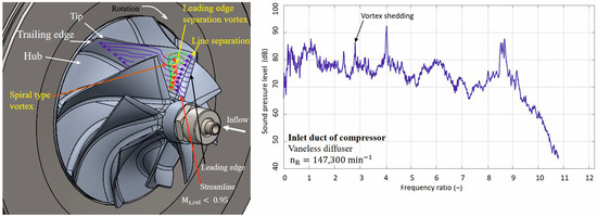
Figure 1.
View showing the presumed formation of the vortex core and streamlines around the leading edge of the compressor wheel blade during operation and the depiction of the presumed source in the spectrum.
From the point of view of the vortex shedding phenomenon, it was found that the emergence of the phenomenon can be defined through Kelvin–Helmholtz instabilities. Chen [24] described the instability for the compressor impeller as follows. Kelvin–Helmholtz instability refers to shear layer instability. A large velocity gradient across the shear layer makes the layer unstable. There is an increased occurrence in the impellers of centrifugal compressors, and the phenomenon occurs near the leading edge when the mass flow of the compressor is reduced. The generated flow passes from the tip of the leading edge of the discharge side of the blade to the suction side of the blade. This separating flow is highly whirling and moves at a different velocity than the surrounding fluid flows, creating an unstable shear layer. The author defined the described event through the frequency of excitation, i.e., as twice the frequency of rotation of the rotor. In [24], the author developed a study of the vortex shedding phenomenon for a centrifugal compressor with the mentioned parameters.
The occurrence of the shedding vortex phenomenon is related to the speed value in the inlet part of the compressor impeller. Dorney and Davis [25] reported the value of the achieved velocity of the working medium during the experiments. In the experiments, the inlet flow in the axial direction was considered, and the velocity value in the inlet part to the impeller reached the value M1rel = 0.12 [25]. Based on the set definition of the event through the excitation frequency, the expected frequency can be expressed according to [24,25,26,27] in the range (0.33–0.5)fBPF (see Table 1).

Table 1.
List of parameters of centrifugal compressors mentioned in studies investigating the aerodynamic phenomenon of the vortex shedding type.
2.2. Tip Clearance Phenomena
Another aerodynamic source of noise related to the continuous flow of the working medium in a centrifugal compressor can be designated as TCN. The occurrence of the TCN phenomenon can be related to the clearance value between the tipping edges of the impeller blades and the wall of the compressor casing. This is one of the sources of the noise of the centrifugal compressor. In the case that TCN occurs, the mass flow rate at the inlet to the compressor is lower than the proposed flow rate. It follows from the above that at a certain clearance value, a secondary flow accompanied by vortices occurs during compressor operation conditions. Vortices formed from the secondary flow are generated through radial pressure gradients in the impeller region. The clearance between the tipping edges of the blades and the casing wall defines the part of the flow field in which the working medium reaches a low value of momentum. Due to the influence of radial pressure gradients, the medium with low momentum cannot follow the main direction of the vortex flow; thus, it turns back to the area with a lower pressure value. During the rotation of the medium to the area with a lower pressure value, the formation of spirals vortices and of a leaking flow may occur.
The aerodynamic noise source described can be identified if the supersonic velocity is not reached during the operation of the centrifugal compressor. Raitor and Neise [8] stated the assumption that M1rel < 0.95, which is related to the operation of the centrifugal compressor at subsonic velocity and the formation of TCN. In general, this is the resulting secondary flow that flows back towards the inlet, due to the gap between the edges of the impeller blades and the wall of the compressor casing. The source of TCN can be identified in a radial centrifugal compressor in the inlet section of the compressor. In the inlet part of the compressor, a dominant noise source of TCN occurs at a lower rotation speed and subsonic velocity [8,24]. Similarly, it is possible to prove the occurrence of TCN in a radial compressor in the outlet pipe, but only if the conditions of the velocity and rotation speed of the compressor are met. The occurrence of TCN in the outlet pipe is significantly influenced by the use of a diffuser. The excitation frequency of the TCN can be determined as follows:
where εR = (0.36–0.64)zR, as defined by [8].
Specific factors significantly influence the appearance of the mentioned source of noise in the centrifugal compressor. Among the factors are the design dimensions determining the size of the clearance between the tipping edges of the blades and the wall of the compressor casing. The value of the clearance is further influenced during rotation by the deflection of the blades by centrifugal forces, thermal expansion, but also by the stiffness of the bearing system of the impeller.
In a wide range of rotor rotation speeds with subsonic flow conditions, the radial compressor is dominated by tip clearance noise, which is produced by secondary flow through the clearance between the rotor blade tips and the casing wall, which, in turn, leads to the phenomenon of rotational instability observed earlier in axial flow machines. The mentioned phenomenon related to the formation of secondary flow was defined by [8] in the frequency domain through Equation (5).
Galindo et al. [28] stated assumptions in relation to the conditions for the formation of TCN. The tip clearance noise (TCN) dominated the BPF tone for subsonic flow conditions at low compressor speeds. TCN is a narrowband sound observed at frequencies around half the blade passing frequency (BPF) that increases with rotation speed. Alqaradawi et al. [29] reported on the generated flow through the clearance between the compressor casing and the blade tipping edges. The vortex structure, which was already formed from the leading edge, gradually passed over the tipping edge of the blade, which also confirms the shape of the streamlines [28]. The process of TCN formation in a centrifugal compressor was described by Swamy and Pandurangadu [30]. The TCN in the centrifugal compressor caused leakage of pressurized fluid from the pressure surface to the suction surface of the impeller blade, resulting in a complex flow field and affecting performance.
Towards operating conditions characterized by low mass flow, the time-averaged pressure fields bound to the rotor blades are more asymmetric. This will increase the broadband acoustic sound level by approximately 2–4 dB. The change can be observed in static interference modes at all frequencies. The point spectra of sound pressure level (SPL) show narrowband characteristics in this frequency interval, i.e., εR > 1 [31]. The noise of TCN was identified in the range of spectra in the range (0.5–0.9)εR [32]. Experiments confirm the existence of a tone at approximately 70% of the rotor rotation frequency at the indicated operating point. We attribute this to the failure caused by tip clearance and rotating stall [20].
In the case of the comparison of centrifugal compressors when evaluating the TCN noise source, the relative tip clearance parameter is introduced. In prior studies [30], researchers defined the relative value of tip clearance as the ratio of the clearance of the wheel blades t and the width of the blades at the exit from the impeller b2 by the equation t/b2. The ratio defining the clearance tip was expressed as a percentage. Parameters t and b2 express the relative tip clearance, and their position in the compressor is shown in Figure 2a. The relative tip clearance is used for the purpose of assessing the impact of different designs of the compressor in terms of performance and, at the same time, in terms of generated values of sound pressure levels. With an increased tip clearance value, a significant pressure difference occurs between the suction and pressure side of the impeller blade. The described pressure difference causes a secondary flow in the compressor during operation. The direction of the secondary flow in the impeller is shown in Figure 2b.
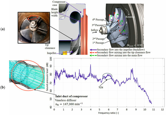
Figure 2.
View showing (a) a centrifugal turbocharger compressor with marked parameters defining the relative clearance of the tip and (b) the assumed direction of the secondary flow in the impeller during the operation of the compressor at the occurrence of TCN with the assumed identification in the frequency spectrum.
Identification of the TCN sound source in centrifugal compressors requires certain assumptions that have been presented in previous publications [8,19,27,28,29]. From the point of view of the operating condition of the compressor, TCN itself dominates at lower operating rotating speeds. At the mentioned compressor speeds, a secondary flow is created, which passes through the clearance between the tipping edges of the blades and the wall of the compressor. The passing secondary flow generates a narrowband sound. At high compressor speeds, TCN cannot be identified. Compressor parameters from individual studies are presented in Table 2, which are used for TCN identification purposes. On the basis of research from prior publications, it is possible to assume the formation of TCN in centrifugal compressors at subsonic velocities. This was the value of the relative velocity of the working medium in the input part of inducer of the impeller, respectively, at the tipping edges of the inducer. When the phenomenon occurred, it was necessary to consider reaching subsonic velocity in the described location with a defined condition M1rel < 0.95, which is confirmed by previous studies [8,27,31]. On the basis of the set definitions of the phenomena, the expected frequency of the phenomenon can be expressed according to [8,19,27,28,29] in the range (0.3–0.9)fBPF through the excitation frequency.

Table 2.
List of parameters of centrifugal compressors mentioned in studies investigating the aerodynamic phenomenon of the TCN type.
In the case of comparing the range of the predicted frequency of the vortex shedding phenomenon and the range of the frequency of the TCN phenomenon, the values overlap. This is the maximum range value for the vortex shedding phenomenon and the minimum range value for the TCN phenomenon. Both phenomena can be estimated in the above overlapped ranges. When identifying the TCN phenomenon, one can consider frequency values that are in the frequency spectrum bounded by a narrow band. The band in the frequency spectrum defines the frequency range in which the identified TCN frequency is located. When identifying the vortex shedding phenomenon, one can consider the frequency values that appear in the frequency spectrum as one separate value.
2.3. Buzz-Saw Phenomena
In a centrifugal compressor, in addition to the vortex shedding phenomenon and the TCN phenomenon, from the point of view of aerodynamics, one more phenomenon generating noise can be identified. If, during compressor operation, supersonic velocity is reached at the tipping edges of the inducer and at the tipping edges of the impeller at the output, respectively, the condition of M1rel > 0.95 is met, it is possible to define another aerodynamic phenomena under the described conditions. For example, if supersonic conditions occur in a compressor, the dominant frequency of the acoustic sound is caused by the blade passing frequency and its multiples [32]. The event described is expressed by the excitation frequency. Equation (3) can be used to determine the excitation frequency. The calculation of the frequency ratio εR for the buzz saw source, which enters Equation (3), defines the phenomena as super-harmonic. In the case of the acoustic spectrum, taking into account the aerodynamic assumptions, what is known as a buzz-saw occurs.
In terms of the assumptions of the generated aerodynamic phenomena in a centrifugal compressor, Sharma et al. [32] conducted research on this subject. Low-speed operation corresponded to subsonic conditions dominated by TCN as a narrowband sound. A narrowband sound was identified at approximately half the BPF. At higher operating speeds corresponding to transonic conditions, the spectrum was dominated by buzz-saw tones and BPF. Under specific operation conditions, shock pressure waves occurred in the area of the channels of the rotating blades of the impeller, which caused harmonic oscillations of the wheel. The process of the pressure waves reached the character of a saw shape. The occurrence of the noise source was directly related to the achieved velocity in channels with a value of 0.95 < M1rel < 1.14 according to [32].
The main source of the buzz-saw noise was the pressure fields of the rotor itself, which were stable in the reference frame of the rotor, i.e. pressure fields bound to the rotor. At supersonic velocity, peaks the locked rotor pressure fields were controlled by shock waves bound to the blades. The pressure field of the rotor itself propagated upstream in the inlet pipe [8]. Sharma et al. [32] presented the assumed parts of the impeller blades, which are characterized by reaching supersonic velocities during the generated of the buzz-saw source. The achievement of supersonic conditions was visible at the leading edges of the inducer, and at the outlet edges of the main blades and at the splitter blades.
As already mentioned, the pressure fields of the impeller contain a larger number of rotation modes whose velocity is the same as the rotation speed of the impeller. And in the case of the buzz-saw source, each of the impeller speed harmonics is assumed to contain one azimuthal mode. Similar assumptions were mention by Raitor and Niese [8], and they defined the calculation of the angular frequency ωM for the described modes. The essential thing was that the shock waves were created around the edges of the blades. The described shock waves were bound to the edges of the blades, and eventually caused the buzz-saw noise. This is the primary source of noise in transonic axial compressors [8]. The intensities of shock waves are sensitive to the blade geometry and the relative position of the blades. Appropriate blades design can help reduce the intensity of shock waves, which are believed to eventually reduce the tonal sound [33]. In a previous study [24], Chen described the operating conditions of a turbocharger compressor, where supersonic flow was generated in the compressor flow particles, causing the buzz-saw phenomenon. A notable feature was the sharp pressure spike at the leading edge of the blade. This is caused by the impact of the entrance edge of the arc and the discontinuity of the curvature of the blade surface in the area of the leading edge. The main source of the buzz-saw noise was the pressure field of the rotor itself, which was stable in the reference frame of the rotor. At supersonic velocities, this pressure field was dominated by shock and expansion waves that propagated upstream of the compressor. Shock waves were located at or near the leading edge of the blades, while expansion waves were coupled to the blades [34]. For the purpose of comparison and subsequent assessment of suitability for identification needs, compressor parameters from individual studies were presented. At the same time, for the purposes of comparison, the parameters of the compressor from the experimental part were listed. In another publication [8], a study of the inducer of the buzz-saw phenomenon for a centrifugal compressor was developed. The parameters of the compressor are listed in Table 2. Similarly, for the centrifugal compressor from another study [32], the compressor parameters are also described in Table 2. The buzz-saw phenomenon mentioned in prior studies [24] was investigated for a centrifugal compressor, the parameters of which are presented in Table 3. The assumed formation of shock waves in the area of the inlet edges of the impeller blades, and the supersonic speeds achieved, is shown in Figure 3.

Table 3.
List of parameters of centrifugal compressors mentioned in studies investigating the aerodynamic phenomenon of the buzz-saw type.
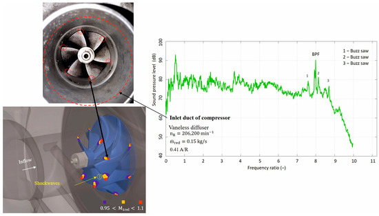
Figure 3.
A view showing the expected formation of shock waves in the area of the inlet leading edges of the blades at supersonic flow velocities in the impeller during compressor operation in the case of a buzz-saw based on [31] and an example of the identification of a noise source in the frequency spectrum.
The speed of the working medium in the mentioned part must reach supersonic velocity, a similar assumption was made by [8,32,35]. At subsonic velocity, the pressure field of the rotor impeller is not affected by shock and expansion waves. When supersonic velocities are reached, the pressure field of the impeller is affected by shock and expansion waves. The generated expansion waves are bound to the blades, and the generated shock waves can be located near the leading edge of the blades. Acting shock and expansion waves, deviations in the geometry of the individual blades of the wheel, and deviations in the position of the blades generate an irregular pressure curve before entering the impeller. The irregular pressure pattern can be repeated once per wheel revolution. Harmonic excitation of rotation frequencies occurs [36,37]. Shock waves propagate against the direction of flow in the pipeline at different speeds, and the pressure curve takes on the character of an irregular saw-tooth shape. One of the possibilities to achieve a regular sawtooth pressure curve is related to the use of the same geometry of all wheel blades, and the same position of the blades located in the wheel. The radiation of the buzz-saw sound source is significantly manifested in the propagation of waves against the flow direction.
The described frequency reaches a lower value compared to the blade frequency value. Based on the set definitions of the phenomena through the excitation frequency, the expected phenomena frequency can be expressed according to [8,32,34] in the range (0.96–1.1)fBPF.
2.4. Blade Passing Phenomena
Previous sources of negative centrifugal compressor noise were related to aerodynamics. The source of the sound can be identified in the frequency spectrum, which can be determined in terms of the number of blades and the operating speed of the compressor. This is a tonal sound. The tonal sound is produced in a centrifugal compressor due to periodic interactions between the rotating impeller and the compressor casing. In the case of the spiral-shaped compressor, it is assumed that a tonal sound occurs in a place known as the tongue. Another assumed place of origin can be defined in the inlet part of the diffuser of the compressor. The phenomena plot can be labeled as fBPF. Similarly, as with aerodynamic phenomena, it is necessary to determine the excitation frequency. The excitation frequency is defined by Equation (2). The supposed places where the noise source originates in the spiral casing of the compressor is shown in Figure 4.
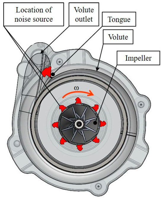
Figure 4.
View showing the assumed locations of the BPF noise source in the centrifugal compressor casing, based on [38].
In a previous study [24], they described the assumption that the BPF noise source was a result of the loading of the blades during rotation. The pressure difference (load) on both surfaces of the blade created a pressure disturbance during rotation. Said interference propagated as a sound wave, the frequency of which was equal to the number of blades and the frequency of rotation of the blades. The amplitude of the sound wave increased with the pressure difference. Raitor and Neise [8] a Liu et al. [16] developed an experimental study of the noise characteristics of the impeller in the inlet and outlet pipes of a centrifugal compressor. In [8], researchers described the influence of tone sound radiation into the pipeline system of the compressor. The tone components in the outlet pipe were higher than in the inlet pipe. This clearly showed that the rotor–stator interaction was important for the sound radiation to the outlet pipe, but not for the radiation to the inlet pipe [8]. With this in mind, the noise of the BPF compressor was radiation primarily from the compressor impeller, and it was extremely difficult for the noise in the diffuser and scroll to propagate through the rotating impeller towards the compressor inlet [16]. The experimental frequency spectrum in the impeller region was dominated by the BPF, with the overall sound level over the entire frequency range compared to the numerical spectrum [32].
Sharma et al. [22] developed a numerical study that dealt with the acoustics of a centrifugal compressor. The study was supplemented with an experimental part and defined the research assumptions from the numerical and experimental part. In the frequency spectrum that was obtained experimentally, the BPF achieved the largest sound pressure value, compared to the numerical spectrum. In the experimental part of the study [29], they defined the influence of the position of the microphone with regard to the achieved BPF value of the noise. The position of the microphone had a large effect on the sound pressure level. If the microphone was located at the outlet of the impeller, there was a more pronounced BPF noise, and its harmonic components were also more pronounced [29]. The experimental results of measurements of the acceleration and sound pressure level at different rotation speeds indicated that the discharge pipe connected to the spiral casing was experiencing excitation to oscillate. This was most intense at the blade passing frequency (BPF) and acted as a major contributor to the compressor noise [35].
Based on the findings stated in the studies of Lee et al. [21], Sharma et al. [22], and Broatch et al. [23], the occurrence of broadband sound appears to occur during compressor operation near the surge limit. In summary, most researchers detected broadband noise near the 1–3 kHz band, which they attributed to operation near surge and backflow related to blade stalling.
3. Materials and Methods
3.1. Experimental Setup
The experimental part of the study was focused on measuring the sound pressure of the turbocharger compressor in an anechoic chamber using six microphones. In order to evaluate and determine the methodology for identifying the aerodynamic sources of compressor sound, a test device was designed that enabled the measurement of boost pressure, temperature, compressor revolutions, acceleration, and flow. The measurement of sound pressure and other parameters was carried out on the compressor of a small Garrett turbocharger of the GT model series. The turbocharger is used to supercharge internal combustion engines, and its parameters are intended for the power range of an internal combustion engine from 37 kW to 97 kW. For measurement purposes, it was necessary to use a complete turbocharger in the test facility, even though the measurements were compressor-oriented. The start of the compressor through the turbine was provided by compressed air from a pressure reservoir located at a distance from the chamber. Air from the reservoir flowed into the inlet part of the turbine through a pressure hose in which the valve was located. Similarly, a pressure hose was connected to the outlet of the turbine, which carried the compressed air away from the turbine. Figure 5a shows the turbocharger placed in the test rig during the experiments. Figure 5b shows experimental centrifugal compressor.
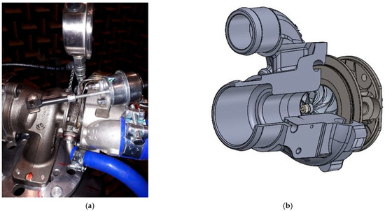
Figure 5.
View showing the experimental turbocharger (a) placed in the test rig; (b) 3D model of the experimental centrifugal compressor.
The experimental turbocharger (the compressor’s parameters are given in Table 4) is an assembly created by a radial turbine. The turbine housing is supplemented by a wastegate valve. The turbine inlet and outlet were connected to the air pressure circuit in the test facility. The turbine impeller, together with the shaft and compressor impeller, form the rotor assembly. The bearing housing connects the turbine housing and the compressor housing and also forms the rotor housing. The housing contains a lubrication system, which was connected to a pressure circulation lubrication system during the experiments. The turbocharger system is complemented by a centrifugal compressor, the inlet and outlet of which were connected to a piping system equipped with sensors.

Table 4.
Centrifugal compressor parameters.
The test equipment used compressed air heated to 600 °C in the combustion chamber as the working fluid. A chamber was located in front of the compressor, where the inlet pressure and temperature were measured and maintained at a constant level. Other measured variables were compressor speed, flow rate, and acceleration. The technical parameters of the sensors are shown in Table 5. The deployment of the sensors and microphones measuring acoustic pressure is shown in Figure 6.

Table 5.
Parameters of the sensors of the test rig.
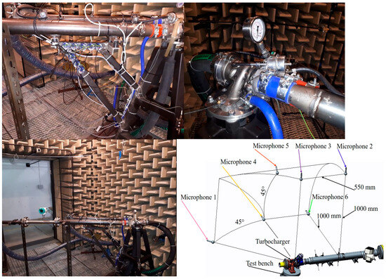
Figure 6.
View showing the designed compressor test rig with sensors for pressure, temperature, speed, flow, and microphone deployment in an anechoic chamber.
In addition to sensors from Table 5, additional technical equipment was used, such as a B&K acoustic camera, power supply, and a data acquisition device with a B&K analyzer. The B&K acoustic camera placed in the position to the right of the compressor monitored the generated noise sources in the compressor space in real time during the measurement process and made it possible to capture stationary, non-stationary, and transient conditions related to the operation of the compressor. Sensors designed to detect boosting pressure and temperature were installed in the inlet and outlet pipes of the compressor. The flowmeter measured the volume flow in the inlet part of the compressor inlet pipe, in the area before the pressure and temperature sensing. Microphones were placed at measurement points surrounding the compressor in an anechoic chamber. The acceleration sensor as part of the technical equipment of the test rig was placed on the outer surface of the inlet flange of the turbine housing. The designed experimental test rig of the turbocharger, which was used during the experiments, is shown in Figure 6.
The procedure for measuring the sound pressure level emitted by a centrifugal compressor was implemented for six speed lines of the compressor. At each revolution line, the acoustic pressure was recorded from six microphones, as well as the course of the volume flow. Furthermore, the course of the turbocharger pressure and temperature of the working medium was recorded. Determining the rotation speed of the compressor provided information about the achievement of the necessary speed for starting the recording of the measured values. Adjusting the position of the valve in the output pipe of the compressor ensured that the compressor rotation speed needed to start recording the measured values were achieved. The measurements of the quantities for specific rotation speed were obtained at five points. From the measured selected data, the course of the quantities in the time interval was obtained, with the assumption of considering the steady state. The data were further used during processing in the Matlab R2021a program for the purpose of FFT analysis and work with the characteristics of the compressor in order to create a methodology for identifying the aerodynamic sources of noise in a centrifugal compressor.
3.2. Results Processing Method
The described aerodynamic sources of compressor noise were identified based on empirical relationships with the assumed position of the source in the frequency spectrum. The use of empirical relationships and the identification of sources required the definition of a methodological procedure. The proposed source identification methodology assumed the use of the measured acoustic signal through microphones, signal processing by FFT analysis, and the use of the EWT method for spectrum segmentation, signal filtering, and signal demodulation. In the segmentation process, several boundaries emerged in the spectrum to which empirical modes can be assigned. The largest spiciness components with the corresponding frequency values in the spectrum were extracted from the empirical modes. Input parameters intended to identify the sources included acoustic pressure, reduced flow rate, compressor speed, temperature, and pressure of the working medium in the area of the wheel intake. They were also used for identification determined values of the relative Mach number of the working medium in the area of the wheel intake. The identification algorithm was designed in the PyCharm 2025.1.1.1 program.
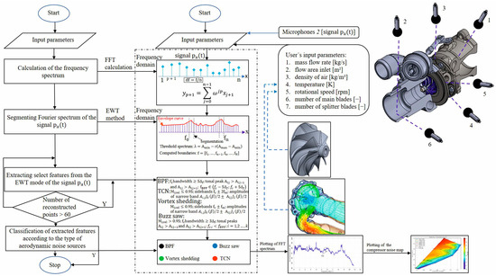
Figure 7.
Flow diagram of the identification of aerodynamic noise sources of the centrifugal compressor based on a measured signal.
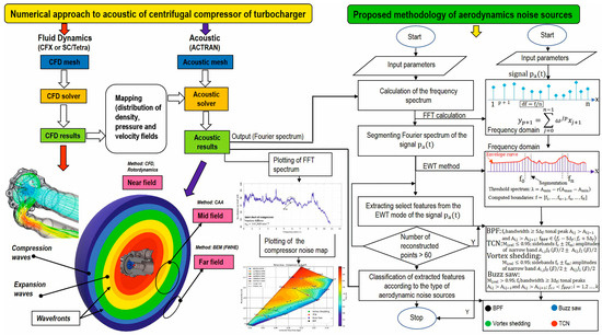
Figure 8.
Flow diagram of the identification of aerodynamic noise sources as a combination of the numerical approach and proposed methodology.
- Step 1: In the first step, it was necessary to process the obtained signal pa(t) through the FFT analysis algorithm. FFT analysis was used in the proposed development diagrams in order to create a spectrum y(p+1).
- Step 2: The spectrum obtained by FFT analysis was subsequently decomposed adaptively by detecting local maxima of the signal through the EWT method.
- Step 3: Extraction of select features from the EWT mode by the demodulation of the signal pa(t).
- Step 4: In order to classify aerodynamic noise sources, the features from the extraction were classified according to individual types.
- Step 5: After reaching convergence, the display of the assumed sources was finished. The running algorithm was terminated.
- Step 6: In last step, the algorithm plotted an FFT spectrum and compressor noise map with the identities of the noise sources of the compressor.
The aforementioned algorithm intended to identify the dynamic sources of the noise of the centrifugal compressor could use the acoustic signal generated from the results of the numerical simulation of the acoustics of the centrifugal compressor. Commercial programs dealing with the numerical solution of acoustics could be used to simulate the acoustics of the reciprocating compressor. When choosing programs, it is necessary to plan the cooperation of the algorithm with the post-processing of the simulation program. From the assumed programs, software from the Hexagon software company (Actran) or Ansys software (Acoustics) can be selected.
4. Results and Discussion
Measurements of the sound pressure level of the compressor were carried out in several operating conditions of the compressor. A series of sound pressure level measurements was made using six microphones, whose task was to record changes in sound pressure, with respect to operating points in the characteristic of the compressor. Figure 9 shows an overview of the points in the compressor characteristic where the sound pressure level measurements were plotted using the PyCharm 2025.1.1.1 program.
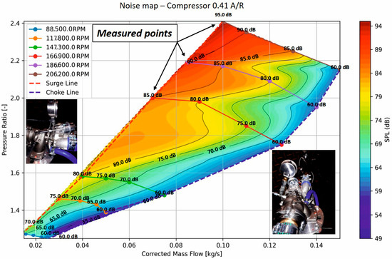
Figure 9.
Compressor noise map with the marked area (points) of sound pressure level measurements.
The sound pressure level results from microphones 5 and 6 were used for the evaluation. Microphone 5 was located between the vertical and horizontal positions, respectively, in the place between microphone 2 and microphone 6. Microphone 6 was placed in a horizontal position, in the space of the inlet and outlet pipes of the compressor. In comparison with the position of microphone 4, microphone 6 provided a more appropriate recording of the progress of the sound pressure level of the compressor, in the case of focusing on aerodynamic sources of noise. For the purposes of evaluation, the values of the frequency ratio for the amplitudes of the levels were obtained for the acoustic pressure values in the frequency spectra for microphones 2, 5, and 6. The obtained values of the frequency ratio, which were tied to a specific amplitude, can be seen in Figure 10. The graphical results from the FFT analysis were plotted using the Matlab R2021a program.
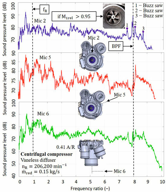
Figure 10.
FFT evaluation in the frequency domain for the compressor rotation speed , at compression ratio and flow rate , with an indication of the expected occurrence of noise sources for better identification of the working condition.
In the spectrum, in addition to the BPF, there were also aerodynamic sources that can be seen in the range from 2 to 8 of the frequency ratio. Furthermore, the rotor rotation frequency fR was marked in the spectrum. In the range from 7 to 9, the expected occurrence of aerodynamics was the represented by identified noise sources. In order to assign the type of aerodynamic source to the value of the frequency ratio in the spectrum, it was necessary to define the conditions. The first condition was related to reaching the Mach number of the inducer blades of the impeller. The condition defined by the value of the relative speed of the working medium M1rel > 0.95 was fulfilled. The second condition is related to the value of the frequency ratio εR determined for a specific aerodynamic event. When comparing the selected value of εR to the estimated source, it was found that the value of the ratio was in the range according to Table 3. The position of the source in the frequency spectrum was included in the assumed range (0.96–1.1)fBPF, which was given in Section 2.3.
The estimated aerodynamic source can be called the buzz-saw. In the case of TCN source identification, the same procedure can be used. The first condition was related to the value of the relative Mach number of the working medium in the inducer of the impeller, which was not met, i.e., M1rel < 0.95. The second condition was not met, because it was not possible to clearly determine the area suitable for assignment in the spectrum narrowband sound. The last verified aerodynamic source of the centrifugal compressor, mentioned in Section 2.1, was created in the case of meeting the condition of the relative Mach number of the working medium in the inducer of the impeller. The condition assumed the character of non-fulfillment if the relative Mach number of the inducer of the impeller M1rel > 0.95 was reached. When meeting the first condition, a source could be identified in the spectrum below the value of 4.
The next examined spectrum corresponded to a compressor speed . Figure 11 shows the results of the FFT analysis for the compressor rotation speed .
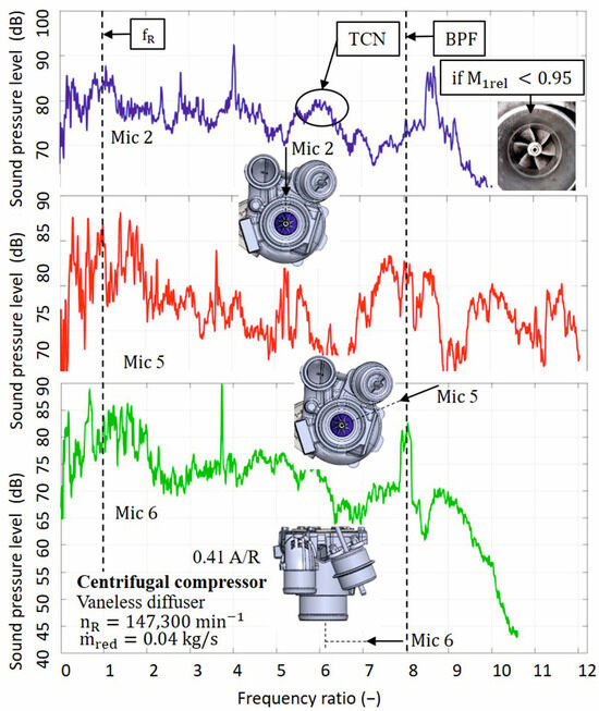
Figure 11.
FFT evaluation in the frequency domain for compressor rotation speed , at a compression ratio of and a flow rate of with an indication of the expected occurrence of noise sources for better identification of the working condition.
In the spectrum for revolutions nR = 147,300 min−1, the BPF noise source was identified at the highest achieved sound pressure value of 82 dB. In the spectrum, there were several maxima of sound pressure values in the range from 2 to 7. The procedure for identifying sound sources in the spectrum was the same as for the previous revolutions of the compressor. The position of the source in the frequency spectrum could be included in the assumed range, which was given in Section 2.2. The fulfillment of the second condition for the TCN source was related to the calculation of the frequency ratio εR. The calculated value of εR was in the range according to Equation (5). In the spectrum, it was possible to identify an area at the value of the frequency ratio of 6, which was assigned to narrowband sound. The position of the source in the frequency spectrum was included in the expected range from Section 2.2. The identification of the buzz-saw noise source for the described revolutions was developed in the spectrum above 4. The first identification condition was related to the required value of the Mach number. The condition was not met.
Aerodynamic sources in the frequency domain could be plotted in the compressor characteristics. The position of the individual sources in the characteristic was expressed by the points, which were defined by the dependence of the reduced mass flow and speed lines. In the characteristic of the compressor, an area with a certain distribution of points representing noise sources was created. The number of points and the position were directly related to the identified sources of the frequency domain depending on the reduced speed of the compressor. The area characteristic of the compressor, which was filled by the points, allowed the assignment of a specific aerodynamic source to a specific point.
5. Conclusions
Processing the results of centrifugal compressor measurements was one of the objectives of the study. The obtained measurement results included the values of the boost pressure, mass flow rate, compressed air temperatures, and acoustic pressure for the specified compressor speeds. The acoustic pressure values were processed using the Matlab program to create FFT analysis spectra. The FFT spectra were used in the proposed methodology for identifying aerodynamic noise sources. Another objective was to propose a methodology for identifying compressor noise sources.
The proposed methodology made it possible to identify the described sources, such as vortex shedding, TCN, buzz-saw, and BPF.
The methodology assumed the processing of the acoustic pressure signal necessary for the functionality of the proposed algorithm. Further development of the methodology resulted in the connection of the proposed algorithm and the numerical simulation of compressor aeroacoustics. Examples of identifying aerodynamic noise sources in FFT spectra were determined. Another result of the identification was the compressor map with a specified compressor noise map. The compressor map with the noise map and FFT spectra were created as outputs from the identification methodology.
The advantages of the study aimed at identifying the aerodynamic sources of centrifugal compressor noise were based on the possibility of directly verifying the assumptions published in other studies on a real turbocharger compressor. Another advantage was related to the use of measured results and FFT analysis. FFT analysis enabled faster identification of the assumed source of compressor noise through the frequency domain. In the case of determining the methodology for assigning maximum frequency values to a specific noise source in the frequency spectrum, the identification time was shortened compared to the results of numerical simulation of aeroacoustics. Based on a defined procedure, the proposed algorithm identified the resources in relation to the operating state of the compressor.
The study has the following limitations:
- -
- Its conclusions cannot be automatically applied to other compressors.
- -
- The influence of the working medium temperature on the compressor’s acoustic pressure results was not monitored.
- -
- The source of noise could also be the result of the dynamics of the rotor or turbine itself.
These areas also point to the direction of further research, along with the possibility of optimizing the algorithm for transonic conditions.
Author Contributions
Conceptualization, J.D. and P.N.; methodology, P.N.; software, J.D.; validation, J.D.; formal analysis, V.C.; investigation, J.D.; resources, V.C.; data curation, J.D.; writing—original draft preparation, J.D.; writing—review and editing, V.C. All authors have read and agreed to the published version of the manuscript.
Funding
This research received no external funding.
Data Availability Statement
The raw data supporting the conclusions of this article will be made available by the authors on request.
Conflicts of Interest
The authors declare no conflicts of interest.
Abbreviations
The following abbreviations are used in this manuscript:
| BPF | Blade passing frequency |
| FFT | Fast Fourier transformation |
| RO | Rotating order |
| R&RI | Rotating and rotating instabilities |
| SPL | Sound pressure level |
| SV | Vortex shedding of noise source |
| TCN | Tip clearance noise |
References
- Pakle, S.; Jiang, K. Design of a high-performance centrifugal compressor with new surge margin improvement technique for high speed turbomachinery. Propuls. Power Res. 2018, 7, 19–29. [Google Scholar] [CrossRef]
- Payri, F.; Serrano, J.; Piqueras, P.; García-Afonso, O. Performance Analysis of a Turbocharged Heavy Duty Diesel Engine with a Pre-turbo Diesel Particulate Filter Configuration. SAE Int. J. Engines 2011, 4, 2559–2575. [Google Scholar] [CrossRef]
- Bermúdez, V.; Luján, J.M.; Piqueras, P.; Campos, D. Pollutants emission and particle behavior in a preturbo aftertreatment light-duty diesel engine. Energy 2014, 66, 509–522. [Google Scholar] [CrossRef]
- Bermúdez, V.; Serrano, J.R.; Piqueras, P.; García-Afonso, O. Assessment by means of gas dynamic modelling of a pre-turbo diesel particulate filter configuration in a turbocharged HSDI diesel engine under full-load transient operation. Proc. Inst. Mech. Eng. Part D J. Automob. Eng. 2011, 225, 1134–1155. [Google Scholar] [CrossRef]
- Serrano, J.; Climent, H.; Guardiola, C.; Piqueras, P. Methodology for characterization and simulation of turbocharged diesel engines combustion during transient operation. Appl. Therm. Eng. 2009, 29, 150–158. [Google Scholar] [CrossRef]
- Payri, F.; Benajes, J.; Galindo, J.; Serrano, J.R. Modelling of turbocharged diesel engines in transient operation. Part 2: Wave action models for calculating the transient operation in a high speed direct injection engine. Proc. Inst. Mech. Eng. Part D: J. Automob. Eng. 2002, 216, 479–493. [Google Scholar] [CrossRef]
- Galindo, J.; Serrano, J.; Climent, H.; Tiseira, A. Experiments and modelling of surge in small centrifugal compressor for automotive engines. Exp. Therm. Fluid Sci. 2008, 32, 818–826. [Google Scholar] [CrossRef]
- Raitor, T.; Neise, W. Sound generation in centrifugal compressors. J. Sound Vib. 2008, 314, 738–756. [Google Scholar] [CrossRef]
- Liu, C.; Cao, Y.; Liu, Y.; Zhang, W.; Ming, P.; Ding, S. Numerical and experimental analyses of intake silencer and its effects on turbocharger compressor performance. Adv. Mech. Eng. 2019, 11, 1687814019826677. [Google Scholar] [CrossRef]
- Gagliardi, G.; Tedesco, F.; Casavola, A. Turbocharger Rotational Speed Estimation via Acoustic Measurements. IFAC-PapersOnline 2019, 52, 273–278. [Google Scholar] [CrossRef]
- Allam, S. Low Noise Intake System Development for Turbocharged I.C. Engines Using Compact High Frequency Side Branch Resonators. Adv. Powertrains Automot. 2015, 1, 12–23. [Google Scholar] [CrossRef]
- Rämmal, H.; Abom, M. Acoustics of Turbochargers. In Proceedings of the SAE 2007 Noise and Vibration Conference and Exhibition, St. Charles, IL, USA, 15–17 May 2007; pp. 1–13. [Google Scholar] [CrossRef]
- Veloso, R.; Elnemr, Y.; Reich, F.M.; Allam, S. Simulation of Sound Transmission through Automotive Turbochargers. In Proceedings of the 7th International Styrian Noise, Vibration & Harshness Congress: The European Automotive Noise Conference, Graz, Austria, 3–15 June 2012; pp. 1–14. [Google Scholar] [CrossRef]
- Ishida, M.; Senoo, Y.; Ueki, H. Secondary Flow Due to the Tip Clearance at the Exit of Centrifugal Impellers. In Proceedings of the ASME 1989 International Gas Turbine and Aeroengine Congress and Exposition, Toronto, ON, Canada, 4–8 June 1989; pp. 1–8. [Google Scholar] [CrossRef]
- Anish, S.; Sitaram, N.; Kim, H. Study of Secondary Flow Modifications at Impeller Exit of a Centrifugal Compressor. J. Fluid Dyn. 2012, 2, 248–256. [Google Scholar] [CrossRef]
- Liu, C.; Cao, Y.; Zhang, W.; Ming, P.; Liu, Y. Numerical and experimental investigations of centrifugal compressor BPF noise. Appl. Acoust. 2019, 150, 290–301. [Google Scholar] [CrossRef]
- Chmelko, V.; Garan, M.; Šulko, M.; Gašparík, M. Health and Structural Integrity of Monitoring Systems: The Case Study of Pressurized Pipelines. Appl. Sci. 2020, 10, 6023. [Google Scholar] [CrossRef]
- Gancedo, M.; Guillou, E.; Gutmark, E. Effect of bleed slots on turbocharger centrifugal compressor stability. Int. J. Heat Fluid Flow 2018, 70, 206–215. [Google Scholar] [CrossRef]
- Sun, Z.; Zou, W.; Zheng, X. Instability detection of centrifugal compressors by means of acoustic measurements. Aerosp. Sci. Technol. 2018, 82–83, 628–635. [Google Scholar] [CrossRef]
- Mendonça, F.; Baris, O.; Capon, G. Simulation of Radial Compressor Aeroacoustics Using CFD. In Proceedings of the ASME Turbo Expo 2012, Copenhagen, Denmark, 11–15 June 2012; pp. 1823–1832. [Google Scholar] [CrossRef]
- Lee, I.; Selamet, A.; Kim, H.; Kim, T.; Kim, J. Design of a Multi-Chamber Silencer for Turbocharger Noise. SAE Int. J. Passeng. Cars—Mech. Syst. 2009, 2, 1339–1344. [Google Scholar] [CrossRef]
- Sharma, S.; Broatch, A.; García-Tíscar, J.; Allport, J.M.; Nickson, A.K. Acoustic characterisation of a small high-speed centrifugal compressor with casing treatment: An experimental study. Aerosp. Sci. Technol. 2019, 95, 105518. [Google Scholar] [CrossRef]
- Broatch, A.; Ruiz, S.; García-Tíscar, J.; Roig, F. On the influence of inlet elbow radius on recirculating backflow, whoosh noise and efficiency in turbocharger compressors. Exp. Therm. Fluid Sci. 2018, 96, 224–233. [Google Scholar] [CrossRef]
- Chen, H. Noise of Turbocharger Compressors. In Proceedings of the 17th International Symposium on Transport Phenomena and Dynamics of Rotating Machinery (ISROMAC2017), Maui, HI, USA, 16–21 December 2017; pp. 1–15, ISSN hal-02376818. [Google Scholar]
- Dorney, D.J.; Davis, R.L. Centrifugal Compressor Impeller Aerodynamics (A Numerical Investigation). In Proceedings of the ASME 1990 International Gas Turbine and Aeroengine Congress and Exposition, Brussels, Belgium, 11–14 June 1990; pp. 1–12. [Google Scholar] [CrossRef]
- Bousquet, Y.; Binder, N.; Dufour, G.; Carbonneau, X.; Trebinjac, I.; Roumeas, M. Numerical Investigation of Kelvin–Helmholtz Instability in a Centrifugal Compressor Operating Near Stall. J. Turbomach. 2016, 138, 071007. [Google Scholar] [CrossRef]
- Hong, S.; Huang, G.; Yang, Y.; Liu, Z. Introduction of DMD Method to Study the Dynamic Structures of a Three-Dimensional Centrifugal Compressor with and without Flow Control. Energies 2018, 11, 3098. [Google Scholar] [CrossRef]
- Galindo, J.; Tiseira Izaguirre, A.O.; Navarro, R.; López, M.A. Influence of tip clearance on flow behavior and noise generation of centrifugal compressors in near-surge conditions. Int. J. Heat Fluid Flow 2015, 52, 129–139. [Google Scholar] [CrossRef]
- Alqaradawi, M.; Shahin, I.; Gadala, M.; Badr, O. Aeroacoustic Simulation for NASA CC3 Centrifugal Compressor Operating at off Design Condition. MATEC Web Conf. 2016, 70, 030047. [Google Scholar] [CrossRef]
- Swamy, S.M.; Pandurangadu, V. Tip Clearance Effects on Performance of a Centrifugal Compressor. Int. J. Sci. Eng. Res. 2014, 5, 1027–1034. [Google Scholar]
- Sundström, E.; Semlitsch, B.; Mihăescu, M. Acoustic signature of flow instabilities in radial compressors. J. Sound Vib. 2018, 434, 221–236. [Google Scholar] [CrossRef]
- Sharma, S.; Broatch, A.; Tíscar, J.; Allport, J.; Nickson, A. Acoustic characteristics of a ported shroud turbocompressor operating at design conditions. Int. J. Engine Res. 2020, 21, 1454–1468. [Google Scholar] [CrossRef]
- Vacula, J.; Novotný, P. An Overview of Flow Instabilities Occurring in Centrifugal Compressors Operating at Low Flow Rates. J. Eng. Gas Turbines Power 2021, 143, 111002. [Google Scholar] [CrossRef]
- Wang, P. Multi-Objective Design of a Transonic Turbocharger Compressor with Reduced Noise and Increased Efficiency. Doctoral Dissertation, University College London, London, UK, 2017. [Google Scholar]
- Alenius, E. CFD of Duct Acoustics for Turbocharger Applications. Doctoral Dissertation, Royal Institute of Technology, Stockholm, Sweden, 2010. [Google Scholar]
- Zhang, Q.; Mao, Y.; Zhou, H.; Zhao, C.; Diao, Q.; Qi, D. Vibro-acoustics of a pipeline centrifugal compressor: Part II. Control with the micro-perforated panel. Appl. Acoust. 2018, 132, 152–166. [Google Scholar] [CrossRef]
- Sundström, E.; Semlitsch, B.; Mihăescu, M. Generation Mechanisms of Rotating Stall and Surge in Centrifugal Compressors. Flow Turbul. Combust. 2018, 100, 705–719. [Google Scholar] [CrossRef]
- Nguyen, V.T.; Danlos, A.; Ravelet, F.; Deligant, M.; Solis, M.; Khelladi, S.; Bakir, F. CFD Analysis to explain the Operating Range Extension observed during Operation in Co-rotating Mode of a Twin-impeller Centrifugal. E3S Web Conf. 2021, 321, 02011. [Google Scholar] [CrossRef]
Disclaimer/Publisher’s Note: The statements, opinions and data contained in all publications are solely those of the individual author(s) and contributor(s) and not of MDPI and/or the editor(s). MDPI and/or the editor(s) disclaim responsibility for any injury to people or property resulting from any ideas, methods, instructions or products referred to in the content. |
© 2025 by the authors. Licensee MDPI, Basel, Switzerland. This article is an open access article distributed under the terms and conditions of the Creative Commons Attribution (CC BY) license (https://creativecommons.org/licenses/by/4.0/).