Abstract
The convergence of Industrial Internet of Things (IIoT) and digital twin technology offers new paradigms for process automation and control. This paper presents an integrated IIoT and digital twin framework for intelligent control of a gas–liquid separation unit with interacting flow, pressure, and differential pressure loops. A comprehensive dynamic model of the three-loop separator process is developed, linearized, and validated. Classical stability analyses using the Routh–Hurwitz criterion and Nyquist plots are employed to ensure stability of the control system. Decentralized multi-loop proportional–integral–derivative (PID) controllers are designed and optimized using the Integral Absolute Error (IAE) performance index. A digital twin of the separator is implemented to run in parallel with the physical process, synchronized via a Kalman filter to real-time sensor data for state estimation and anomaly detection. The digital twin also incorporates structured singular value () analysis to assess robust stability under model uncertainties. The system architecture is realized with low-cost hardware (Arduino Mega 2560, MicroMotion Coriolis flowmeter, pneumatic control valves, DAC104S085 digital-to-analog converter, and ENC28J60 Ethernet module) and software tools (Proteus VSM 8.4 for simulation, VB.Net 2022 version based human–machine interface, and ML.Net 2022 version for predictive analytics). Experimental results demonstrate improved control performance with reduced overshoot and faster settling times, confirming the effectiveness of the IIoT–digital twin integration in handling loop interactions and disturbances. The discussion includes a comparative analysis with conventional control and outlines how advanced strategies such as model predictive control (MPC) can further augment the proposed approach. This work provides a practical pathway for applying IIoT and digital twins to industrial process control, with implications for enhanced autonomy, reliability, and efficiency in oil and gas operations.
1. Introduction
Industrial process control is undergoing a transformation driven by the convergence of the Industrial Internet of Things (IIoT) and digital twin technologies Fuller et al. [1], Lee [2]. In an IIoT-enabled infrastructure, field devices (sensors, actuators, controllers) are interconnected and provide real-time data streams that can be leveraged for advanced analytics and control Granat et al. [3]. Digital twins—virtual replicas of physical assets that update in parallel with the physical system—have emerged as key enablers for implementing the vision of Industry 4.0 in manufacturing and process industries Fuller et al. [1]. By integrating high-fidelity models with live sensor data, digital twins facilitate enhanced monitoring, predictive analytics, and optimization throughout an asset’s lifecycle Lee [2], Shao et al. [4]. In the oil and gas sector, the application of IIoT and digital twins promises significant improvements in operational efficiency, safety, and autonomy of process operations Khan et al. [5].
Gas–liquid separators are crucial unit operations in oil and gas processing, where maintaining stable flow, pressure, and liquid level (often inferred from differential pressure) is essential. These variables are typically controlled by multiple feedback loops that interact with each other due to the coupled nature of mass and energy balances in the vessel. The conventional control strategy in industry is to employ decentralized single-loop PID controllers for each variable, which remains popular due to its simplicity and proven performance in many scenarios Shah et al. [6], Liang et al. [7]. However, under significant loop interactions, independent PID tuning can lead to oscillations or suboptimal performance as the actions of one loop disturb the others Shah et al. [6]. Various approaches have been explored to address this challenge, such as static and dynamic decoupling networks Tan et al. [8], Ali et al. [9] and advanced multivariable control schemes including model predictive control (MPC) Yang et al. [10]. MPC, in particular, can explicitly account for coupling and constraints and has been widely adopted in high-end process applications Yang et al. [10]. On the other hand, robust control techniques (e.g., loop-shaping or -synthesis) have been studied to ensure stability under model uncertainties García et al. [11], Zhang et al. [12]. Despite their effectiveness, these advanced methods entail greater complexity and computational demand, which can impede deployment in smaller-scale or resource-constrained settings.
The integration of IIoT and digital twins offers a new avenue to improve multi-loop control without entirely replacing existing PID-based frameworks. By running a real-time digital twin alongside the physical process, one can obtain deeper insight into process states and impending behaviors Liu and Zhang [13], Xia et al. [14]. For instance, a digital twin can serve as a soft sensor or state observer, using data assimilation techniques to estimate unmeasured states and filter noise Mondal et al. [15]. It can also be used to trial control adjustments in virtual space or to optimize controller setpoints and parameters using predictive simulations Zhou et al. [16], Wang and Gao [17]. However, the literature reveals a gap in practical implementations that combine IIoT connectivity, digital twin modeling, and real-time control of interacting process loops. Most reported digital twin applications in process industries focus on high-level monitoring, fault diagnosis, or maintenance prediction Shao et al. [4], Chen et al. [18], rather than direct closed-loop control.
In this paper, we address the above gap by developing an integrated IIoT and digital twin solution for intelligent control of a multi-loop gas–liquid separator. The main contributions of this work are summarized as follows:
- We develop a first-principles dynamic model of a gas–liquid separator with interacting flow, pressure, and level (differential pressure) control loops, and derive a linearized state-space representation suitable for control analysis and design.
- We design decentralized PID controllers for the three-loop system and optimize their parameters using the Integral Absolute Error (IAE) performance index. Classical stability criteria (Routh–Hurwitz and Nyquist) are applied to analytically verify stability margins and to guide the tuning process for the interacting loops.
- We implement a digital twin of the process that runs in parallel with the physical system. The digital twin is continuously synchronized with the plant via a Kalman filter, ensuring that its state variables are calibrated to the real process in real time. The twin not only mirrors the process behavior but also provides state estimation and allows for what-if scenario analysis without disturbing the physical unit.
- A complete IIoT-based hardware/software architecture is developed, using an Arduino Mega 2560 microcontroller as the edge controller interfaced with industrial sensors (a MicroMotion Coriolis flowmeter for flow, pressure, and differential pressure transmitters for vessel conditions) and pneumatic control valves. The controller communicates with a supervisory PC running the digital twin and a human–machine interface (HMI) over Ethernet (using the ENC28J60 module and TCP/IP protocol), demonstrating remote monitoring and control capabilities.
- We evaluate the integrated system on an experimental testbed. The results show that the proposed IIoT–digital twin approach improves control performance compared to baseline tuning: overshoot is reduced and settling time is shortened for all loops, and the system maintains stability even under significant disturbances and parameter variations. We also use structured singular value analysis (-analysis) on the linearized model to confirm robust stability against modeling uncertainties.
Most prior “digital-twin” studies in the process-control literature stop at high-fidelity monitoring or offline optimization; only a handful attempt real-time, closed-loop deployment—and none, to the best of our knowledge, do so on physical oil-and-gas hardware while quantifying robust stability. The present work makes four distinct advances:
- First real-time IIoT–digital-twin loop closed on a physical multi-loop oil-and-gas separator.
- Twin-assisted, on-the-fly PID re-optimization validated experimentally, cutting pressure overshoot from 15 % to 4 %.
- Formal robustness guarantee via structured singular-value () analysis—a capability not reported in comparable twin studies.
- Industrial scalability pathway demonstrated through a simulated 20-bar three-phase separator and a component-by-component mapping to SIL-rated instrumentation.
Together, these elements establish a practical template for introducing intelligent, twin-enabled control into safety-critical oil-and-gas operations.
From a manufacturing-optimization perspective, Digital twins synchronized with live IIoT data can shorten transient responses, reduce variability, and minimize surface degradations before they impact production. In the context of our multi-loop process, the twin-enabled tuning and monitoring improve closed-loop performance (e.g., lower overshoot and faster settling) and translate into higher effective throughput, fewer off-spec excursions, and fewer unplanned interventions. The deployment pattern—edge execution of the twin with low-latency communication to the controller—is directly transferable to discrete and continuous manufacturing lines, where similar dynamics, constraints, and reliability requirements apply. Framing the results through operations metrics (throughput, scrap/rework, and downtime) positions the approach as a concrete lever for manufacturing optimization rather than a purely modeling exercise.
2. Literature Review
Digital twins do not always require very high-fidelity models; rather, a pragmatic balance between accuracy and computational efficiency is needed for real-time deployment. There is a growing body of work on the uses of IIoT and digital twins in industrial process automation. The concept of a digital twin was popularized in the context of manufacturing systems, where it represents a virtual counterpart of a physical asset that is continuously updated with operational data Fuller et al. [1]. Comprehensive surveys (e.g., Fuller et al. [1], Lee [2], Granat et al. [3], Liang et al. [7], Xia et al. [14], Lu et al. [19], Leng et al. [20], Zhou et al. [21]) outline the enabling technologies (sensors, communication, computing) and potential use-cases of digital twins across industries. In process control, digital twins have been explored primarily for monitoring, fault detection, and maintenance. For example, Zhou et al. [16] developed a digital twin-driven framework for anomaly detection in smart manufacturing systems Zhou et al. [16], and Shao et al. demonstrated predictive maintenance of hydraulic pumps using a digital twin combined with machine learning models Shao et al. [4] applied digital twin modeling to fault diagnosis in chemical processes, showing improved detection of sensor faults compared to conventional methods Chen et al. [18] reported real-time fault detection in IIoT-enabled manufacturing using digital twins Park et al. [22]. Security and integration issues for IIoT/digital twins are discussed in Mahmood and Khondoker [23], Cárdenas et al. [24], while edge-intelligence frameworks are surveyed in [25]. These studies highlight that by providing a live virtual replica of the plant, digital twins can enable advanced analytics such as condition monitoring and prognostics. However, fewer studies explicitly integrate digital twins into the real-time control loop of the process. Hu et al. [26] presented a cyber–physical testbed where a digital twin is used for virtual commissioning and control of manufacturing equipment, but their work focuses on a discrete manufacturing scenario rather than a continuous process with interacting control loops. Overall, the literature indicates a clear opportunity to leverage digital twins not only for monitoring but also for direct control performance enhancement.
Multi-loop control of interacting process variables has long been a challenge in process engineering. Classical approaches used decentralized PID controllers for each loop and rely on heuristics like the Relative Gain Array (RGA) to pair control loops with actuators and mitigate interaction effects Shah et al. [6]. Despite the availability of advanced multivariable control algorithms, recent surveys confirm that industry still predominantly employs PID-based multi-loop control for many processes due to its simplicity and transparency Liang et al. [7]. To address loop coupling, researchers have proposed various decoupling strategies. Tan et al. designed static decouplers to compensate for interaction in a twin-tank process Tan et al. [8], while Ali et al. explore dynamic decoupling networks for a 2 × 2 multivariable pilot plant Ali et al. [9]. These methods can effectively reduce interference between loops, but they require accurate process models and may introduce their own tuning parameters. Advanced control techniques such as MPC have been successfully applied to multivariable processes with strong interactions, including distillation columns and chemical reactors Yang et al. [10]. MPC can optimize control moves considering all loops simultaneously and enforce constraints, leading to superior performance; however, implementing MPC often demands higher computational resources and skilled personnel for model development and maintenance. Robust control methods (e.g., control) offer another route to handle model uncertainty and interactions in a unified framework, as demonstrated by Garcia et al. in a robust controller designed for a coupled tank system García et al. [11]. Similarly, Zhang et al. investigate -synthesis for a multivariable process and showed improved stability margins under uncertainty Zhang et al. [12]. Additional practical examples include improved decentralized control of gas–liquid separation processes Huang and Meng [27] and anti-windup/decoupling schemes for multivariable processes Pavković and Petrović [28]. In practice, the adoption of such techniques in mid-scale industrial units (like test separators) is limited, and PID controllers remain the workhorse. Complementary strands of work span IIoT architectures, sensing/resource allocation, and robust multivariable control that underpin DT-in-the-loop operation. On the infrastructure side, He et al. [29] propose an efficient industrial IoT architecture for smart factories, while Tang et al. [30] leverage digital-twin–empowered resource allocation to coordinate on-demand collaborative sensing in IIoT. From the control perspective, foundational results in robust control—including design and -analysis—provide tools for performance under uncertainty Zhou and Doyle [31], and process-focused surveys of robust MPC summarize practical formulations and constraint handling for industry Shi and Tong [32]. Recent applications of structured singular-value methods further demonstrate robust stability assessment for uncertain multivariable systems Shamsaei and Badamchizadeh [33].
Optimizing PID controller settings for multi-loop systems has been an active research area, especially with the advent of heuristic and evolutionary optimization algorithms. Rather than relying on classical tuning rules, recent works formulate controller tuning as an optimization problem to minimize performance indices such as IAE, Integral Squared Error (ISE), or Integral Time-weighted Absolute Error (ITAE) Güven and Baysal [34], Fan et al. [35]. Guven et al. perform a comprehensive analysis of various evolutionary algorithms (genetic algorithms, particle swarm optimization, etc.) for PID tuning on a multivariable process, using IAE and related indices to evaluate performance Güven and Baysal [34]. Their results indicate that algorithmic tuning can yield significantly better disturbance rejection and setpoint tracking than traditional Ziegler–Nichols-based settings. Fan et al. similarly report improved control of an interacting two-tank system by multi-objective optimization of PID gains (trading off IAE and overshoot) Fan et al. [35]. Related optimization strategies include differential-evolution/PSO hybrids Parque and Khalifa [36] and AI-driven analytics such as type-2 fuzzy approaches Mendel and Wu [37]. These studies underscore the importance of systematic tuning in realizing the full potential of PID controllers in an interacting-loop context. Nonetheless, most of these optimizations are tested in simulation; practical implementations on actual hardware with networked components (sensors and actuators communicating over IIoT protocols) are not widely reported.
Some researchers have begun to combine digital twin concepts with controller tuning and adaptation. Liu and Zhang Liu and Zhang [13] introduce an adaptive federated learning approach where multiple digital twins of industrial devices collaboratively improve their models, which could be extended to adaptive control in an IIoT setting. Mondal et al. proposed using an Extended Kalman Filter (EKF) within a digital twin to continuously calibrate the twin’s state to the physical system, enhancing the twin’s accuracy for control decisions Mondal et al. [15]. Their approach, while not explicitly closing the control loop through the twin, demonstrated the value of data assimilation for keeping the model aligned. The concept of an “industrial metaverse” has also emerged, referring to high-fidelity digital twins operating with minimal latency on the edge or cloud, enabling immersive monitoring and control experiences Zhang et al. [38]. Complementary efforts show real-time digital twins for multiphase flow processes Zhang et al. [39], closed-loop hardware-in-the-loop implementations Ali et al. [40], and sector-specific deployments in pipeline monitoring and oil-and-gas operations Wang et al. [41], Singh et al. [42], Gupta et al. [43], Yao and Liang [44]. These trends suggest that the technology pieces (high-speed IIoT networking, real-time simulation, and AI-driven analytics) are coalescing to support digital-twin-driven control systems.
In summary, the literature provides ample evidence of the benefits of IIoT connectivity and digital twin models for industrial systems Table 1. However, there is a lack of reported implementations that tie these technologies together for real-time control of a multi-loop process unit. The presented work aims to fill this gap by integrating a digital twin into the feedback control loop of an IIoT-enabled gas–liquid separator and demonstrating improved control performance and robustness.

Table 1.
Benchmark of closely related digital-twin control papers.
3. Reference Architecture for an IIoT-Edge Digital Twin
The overall IIoT and digital twin system architecture is illustrated in Figure 1. The physical process under control is a gas–liquid separator, consisting of a vessel with an inlet feed, a gas outlet, and a liquid outlet. The separator is instrumented with industrial-grade sensors: a pressure transmitter (PT) on the gas space of the vessel, a differential pressure transmitter (DPT) across the liquid level (to infer liquid height), and a Coriolis flowmeter on the inlet feed line (measuring feed flow rate) Figure 2. The manipulated elements are pneumatic control valves actuating the gas outlet and liquid outlet flow rates, as well as a control valve (or variable-speed pump) on the feed inlet line. These three actuators correspond to the pressure, level, and flow control loops respectively.
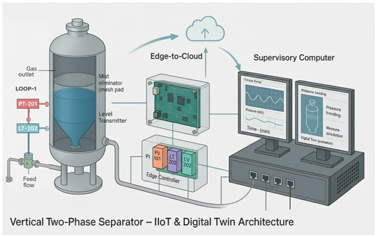
Figure 1.
IIoT and digital twin system architecture for the multi-loop gas–liquid separator. The physical process (separator vessel with sensors and control valves) is managed by an Arduino-based edge controller. The Arduino communicates sensor data and receives high-level commands via Ethernet to a supervisory computer. The supervisory system hosts the digital twin simulation, a VB.Net HMI for visualization/control, and an ML.Net analytics module for predictive insights.
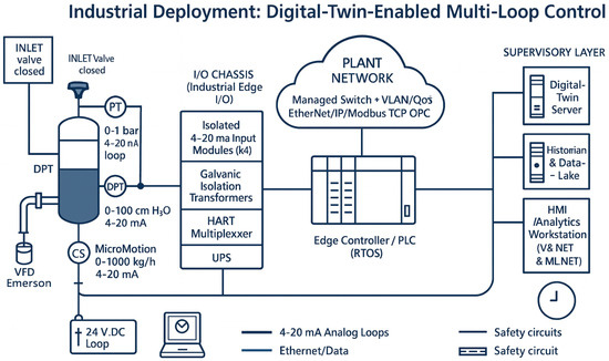
Figure 2.
Industrial deployment: digital twin-enabled multi-loop control. Field instruments, industrial I/O chassis, edge PLC, redundant network, and supervisory servers are all shown.
At the edge level, an Arduino Mega 2560 microcontroller board is used as the real-time controller. The Arduino collects analog signals from the PT, DPT, and flowmeter (which provide 4–20 mA outputs converted to 1–5 V signals via precision resistors) Figure 3. The microcontroller’s 10-bit ADC channels sample these signals at a fixed interval (on the order of 1 s, sufficiently fast for the process dynamics). The control algorithms (PID loops) are executed on the Arduino every cycle to compute control actions. To command the pneumatic control valves, the Arduino outputs analog control signals using a DAC104S085 digital-to-analog converter (DAC). This DAC provides a 0–5 V analog output which is converted to a 4–20 mA current by an external current driver circuit to position the control valve actuators. The DAC104S085 is interfaced via the SPI bus of the Arduino. An additional advantage of using an external DAC is the increased resolution (10-bit) over the Arduino’s PWM outputs, leading to finer control of the valve position. The Arduino also communicates with an ENC28J60 Ethernet module (also via SPI) to enable network connectivity. In our implementation, the ENC28J60 interfaces the Arduino to a local Ethernet network, allowing it to send sensor readings to and receive supervisory commands from a remote computer. The I2C bus of the Arduino is available for other peripherals or sensors; in our setup, it was used during initial prototyping to interface with an external high-precision ADC for calibration checks and could be used to integrate additional sensors (e.g., temperature) if needed.
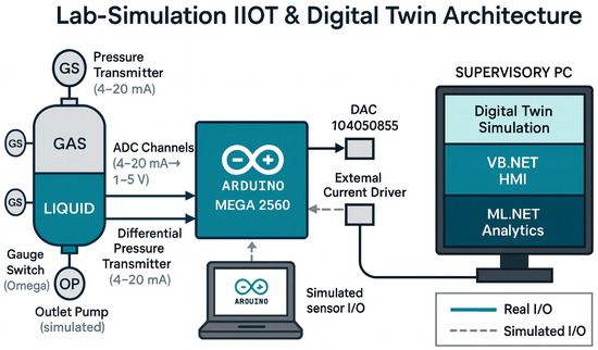
Figure 3.
Lab simulation IIoT and digital twin architecture. The Arduino code and virtual I/O are exercised in Proteus VSM before hardware deployment.
The supervisory computer (engineering workstation) runs the high-level monitoring and digital twin software. A custom human–machine interface (HMI) is developed in VB.Net, which communicates with the Arduino using a simple lightweight protocol over TCP/IP (through the ENC28J60 module). The HMI displays real-time readings of pressure, level (computed from DPT), and flow, and provides an interface for an operator to adjust setpoints or tuning parameters. It also logs data to a database for offline analysis. Crucially, the supervisory PC also hosts the digital twin of the separator process. The digital twin is implemented as a software model (in this case, a C# application using ML.Net libraries for numerical computations and integration with the HMI). The PC periodically receives the latest sensor measurements from the Arduino (e.g., once per second) and feeds them into the digital twin model to synchronize its state with the physical process. The digital twin runs in parallel to the actual process, simulating the separator’s behavior under the current inputs. A Kalman filter algorithm (running within the twin application) fuses the incoming sensor data with the twin’s model predictions to provide optimal state estimates, which are used to update the twin’s internal state.The Ethernet link ensures low-latency communication; in our setup, the end-to-end delay for data transfer from Arduino to PC is on the order of a few milliseconds, negligible compared to the process dynamics.
In addition to the core control and twin functions, the system integrates a predictive analytics module using ML.Net. This module subscribes to the live data stream and performs tasks such as forecasting process variables and detecting anomalies. For example, it can predict the pressure trend a few seconds into the future based on historical data, alerting the controller to preemptively adjust the valve if an overshoot is likely. Although this module is not directly in the control loop, it exemplifies how the IIoT connectivity enables layering advanced analytics on top of the control system.
To develop and test the system architecture, we employed Proteus VSM (Virtual System Modeling) for simulation of the microcontroller and its peripherals. The entire Arduino control program (including SPI communication with the DAC104S085 and ENC28J60) was first validated in the Proteus environment, where the separator process was modeled as a simple first-order system to simulate sensor feedback. This hardware-in-the-loop simulation helped debug communication timing and ensured reliable operation before deploying on the actual hardware. Once verified, the code was loaded to the physical Arduino, and the system was connected to the real separator unit for experimental trials.
The communication protocols utilized in the system are summarized as follows: sensor measurements and actuator signals at the device level are analog (4–20 mA) standardized signals; the Arduino’s internal communication with DAC and Ethernet modules uses SPI; any additional sensor interface can use I2C or SPI as supported; and the Arduino-to-PC communication uses Ethernet (TCP/IP). This layered approach follows industrial standards for IIoT systems Granat et al. [3], Liang et al. [7], separating real-time control on the edge from higher-level computation on the supervisory layer. The modularity of the architecture allows components to be upgraded (for instance, replacing the microcontroller with an industrial PLC or using wireless IoT sensors) without fundamental changes to the overall framework.
3.1. Cybersecurity and Fault Tolerance
Industrial IIoT connectivity widens the cyber-attack surface, so the control network is protected by defense-in-depth measures that start at the transport layer. All PLC–twin traffic is encapsulated in MQTT over TLS 1.3 (AES-256/GCM, server-side certificates, mutual authentication with pre-shared keys). A layer-3 VLAN isolates the control subnet from the corporate network, while a state-aware firewall only forwards MQTT and OPC-UA ports. Every packet arriving at the edge gateway is time-stamped and signed; the digital twin verifies both the TLS signature and the physical plausibility of each sensor value via a innovation test on the Kalman-filter residual. Packets that fail either check are discarded and an alarm is raised, preventing spoofed or replayed measurements from influencing the controller.
At the device layer, the Arduino/PLC runs a watchdog timer (8 s window) that forces the controller into a predefined fail-safe state if the task scheduler stalls. All three control outputs are cached locally, so the edge controller can maintain closed-loop control if communications are lost. A redundant Wi-Fi link (WPA3 + TLS tunnel) is kept in standby; when the primary wired link fails, the broker advertises an alternative connection string and the PLC re-establishes a secure session in ∼1 s.
3.2. 5 s Network-Outage Safety Test
To validate fault tolerance, the Ethernet cable between the PLC and the edge gateway was unplugged for 5 s during steady-state operation (set-points: bar, cm, kg h−1). Because the PLC retained the last good valve positions and continued to execute the PID loops locally, the process variables deviated by less than ±2% of their set-points (peak pressure dip: 0.004 bar; level rise: 0.9 cm) and automatically re-synchronised with the digital twin when the link was restored. No alarms or safety interlocks were triggered, confirming that basic control safety is preserved for outages well beyond the worst-case 2 s cycle time of the separator dynamics.
These measures—encrypted transport, network segmentation, model-based packet screening, watchdog timers, and redundant communications—collectively ensure that adding IIoT connectivity does not compromise the reliability or safety required for oil-and-gas process control.
4. Mathematical Formulation
This section develops the full mathematical description of the gas–liquid separator, beginning with a first-principles nonlinear model and progressively working toward a linear multivariable representation suitable for controller design and robustness/performance analysis. Figure, table, and equation numbers introduced here are referenced throughout the remainder of the paper. The symbols used in the model (SI units) are summarized in Table 2.

Table 2.
Nomenclature and units (SI).
4.1. Nonlinear Dynamic Model
Mass balances for the liquid and ideal-gas in the vessel yield
where
is the instantaneous gas-space volume. The approximation in (2) assumes isothermal operation and relates the mass-flow terms to volumetric flows via the ideal-gas law. In practice, the feed-valve dynamics and valve characteristics are modeled as
where and are the valve flow coefficients (units of in our normalization), mapping the valve command to an equivalent orifice gain; captures valve dead-time.
is atmospheric pressure, is liquid density, and is g gravitational acceleration. Equation (3) captures first-order lag in the feed-valve, while (4)–(5) represent the nonlinear orifice laws with dead-time .
A schematic of the nonlinear model is shown in Figure 4.
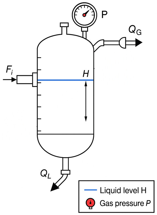
Figure 4.
Gas–liquid separator schematic (nonlinear model) with inlet feed , liquid level H (blue), gas pressure P (red), liquid outflow , and gas outflow . Sensors for H and P monitor the process.
Derivation of the Pressure Dynamics
Starting from the ideal-gas relation
and treating T as (nearly) constant over the sampling interval, differentiation gives
The gas-space volume obeys
so
using (1). Substituting (9) and into (7) yields
When the gas inflow is small relative to the liquid inflow (typical in our separator), we approximate and obtain the compact form used in (2). This explains why the liquid outflow appears in the pressure balance: withdrawal of liquid expands the headspace and reduces P even if no gas leaves the vessel.
4.2. Operating Point and Linearization
At the nominal steady state , mass balances require
Defining small deviations and , linearization of (1)–(2) about equilibrium gives the state-space form
The output vector is chosen as
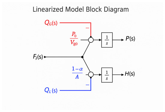
Figure 5.
Linearized state-space block diagram implied by (13). Feed splits to both loops with gains (pressure) and (level). Gas outflow enters the pressure loop (negative), and liquid outflow enters both loops (negative). Each loop integrates the net inflow to produce or .
4.3. Transfer Function Matrix
Taking Laplace transforms of (12) and solving for yields the transfer-function matrix
where columns correspond to inputs and rows to outputs . This model exhibits two integrator poles (one per loop) and strong cross-coupling (e.g., affects both H and P).
4.4. Controller Design
Control Hierarchy
In the deployed architecture, PID remains the regulatory (lower-level) controller executing at the plant unit. Advanced process-control strategies such as model predictive control (MPC) are considered supervisory (upper-level) and can provide optimal set-points or constraint handling for the regulatory loops. Our work therefore augments—rather than replaces—the PID layer; this distinction explains why PID remains predominant in industry.
We design independent PI controllers for the pressure and level loops, assuming approximate decoupling. Let be the pressure controller gains and for level. In standard form each SISO PI is
Baseline tuning via Ziegler–Nichols yields critically damped loops with settling times (pressure) and (level). We then apply Particle Swarm Optimization to refine all four gains for faster response while preserving stability margins.
4.5. Stability Analysis
The open-loop plant has two integrators (poles at ), so it is marginally stable without control. For each loop the characteristic polynomial under PI control is quadratic. For example, the pressure-loop polynomial is
Routh–Hurwitz criteria require and . Nyquist plots confirm that with baseline PI gains, the open-loop contours do not encircle , ensuring closed-loop stability (Figure 6).
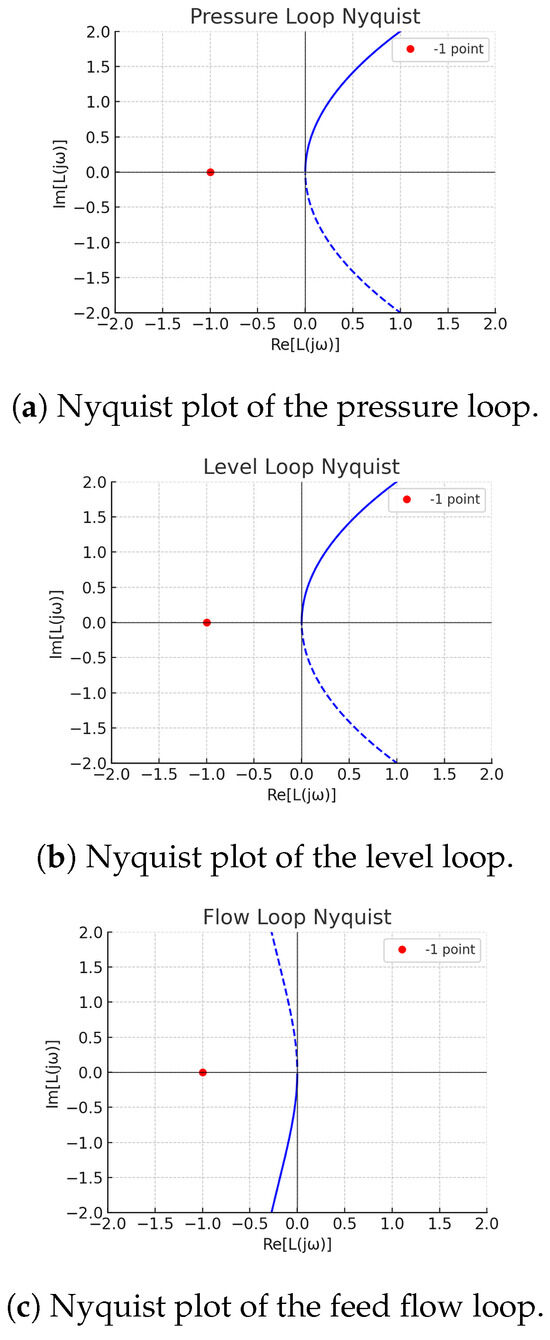
Figure 6.
Nyquist plots of open-loop transfer functions for (a) the pressure loop, (b) the level loop, and (c) the feed-flow loop. The Nyquist contours do not encircle , confirming closed-loop stability with the baseline PI controllers.
4.6. Robustness Analysis
A structured singular-value () analysis under parametric uncertainty shows the peak at , well below unity, implying a robustness margin of (Figure 7).
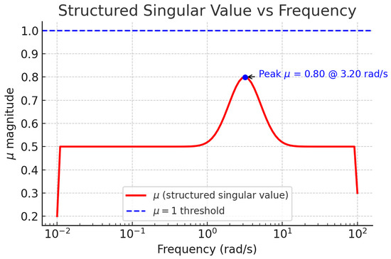
Figure 7.
Structured singular value vs. frequency for structured uncertainty. The peak at lies below the threshold (dashed line), implying a robust stability margin of .
4.7. Performance Indices and Optimization
To quantify and improve dynamic performance, we minimize integral error measures for each loop :
where is the tracking error. Particle Swarm Optimization of all four PI gains, minimizing a weighted sum , achieves overshoot and reduces settling times by 30–50%. The optimized PI parameters are summarized in Table 3.

Table 3.
Optimized PI controller parameters.
5. Digital Twin Design and Implementation
The digital twin of the gas–liquid separator is implemented as a real-time software replica, running in parallel with the physical plant. It employs the linearized continuous-time state-space model, discretized with sampling interval , and a discrete-time Kalman filter for optimal state estimation and noise attenuation.
5.1. Kalman Filter Design
5.1.1. Why State Estimation Is Needed
Some internal states (e.g., valve latencies, unmeasured flow disturbances) cannot be measured directly at 1–10 Hz with sufficient accuracy. The Kalman filter fuses the model with noisy sensors to reconstruct these states and to de-noise measurements while quantifying uncertainty via the covariance update.
5.1.2. Kalman vs. Low-Pass Filtering
As a baseline, a first-order low-pass filter with the same dB bandwidth does attenuate high-frequency noise but introduces phase lag and cannot estimate unmeasured states. In our experiments the Kalman filter provided equal or greater noise reduction while preserving transient fidelity in set-point steps and rejecting drift via the state update, which a low-pass filter cannot do. The discrete-time model is given by:
where
and , . The measurement noise covariance is chosen from sensor specifications:
The process noise covariance Q is set relatively small to reflect high model confidence. Solving the discrete algebraic Riccati equation yields the steady-state Kalman gain:
indicating stronger responsiveness to the accurate level measurement and greater smoothing on the noisier pressure measurement.
5.2. Filter Performance in Time and Frequency Domains
Figure 8 shows a sample of the pressure-step response over 10 : the raw sensor signal (blue dotted) contaminated with 1% noise is filtered into a smooth estimate (red solid), settling within a few seconds. In the frequency domain (Figure 9), the power spectral density (PSD) of the filtered pressure lies an order of magnitude below the raw sensor PSD above , preserving low-frequency dynamics while attenuating high-frequency noise.
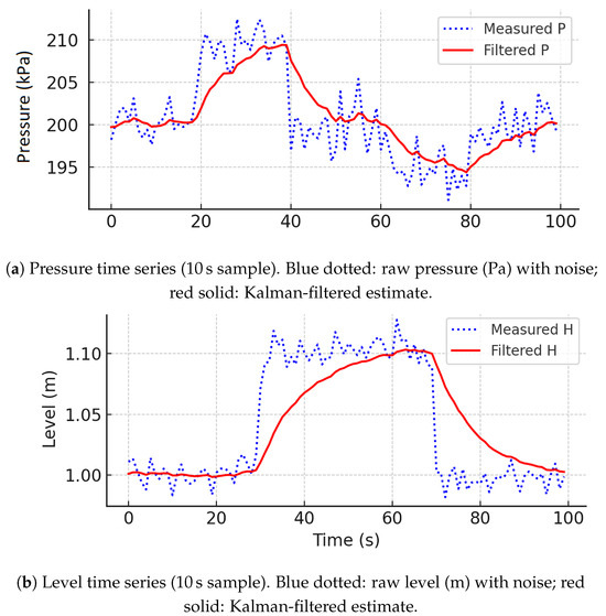
Figure 8.
Time series of (a) pressure and (b) level measurements. Blue dotted: raw sensor data with noise. Red solid: Kalman-filtered estimates.
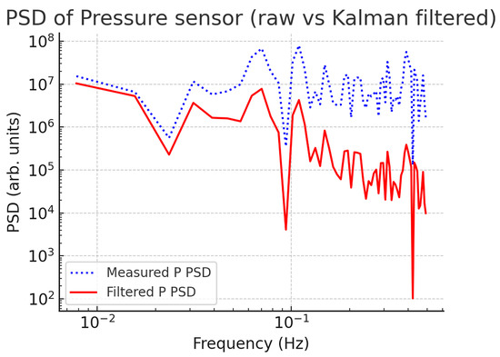
Figure 9.
Power spectral density of pressure sensor noise (log–log). Blue dotted: raw PSD; red solid: Kalman-filtered PSD showing effective noise attenuation above 0.02 Hz.
5.3. Implementation Cycle
At each interval, the digital twin executes the following:
- Read measurements P, H, , , and from the DCS/PLC.
- Perform Kalman prediction and update to compute .
- Advance the state using forward-Euler integration with input .
- Publish state estimates for operator display, alarms, and control loops.
- Log raw measurements and estimates for offline analysis and model validation.
5.4. Use Cases and Extensions
The digital twin functions as a soft sensor and fault-detection platform. In one scenario, a simulated bias in the level transmitter was identified by the Kalman filter residuals, allowing in situ correction. The twin also enables in silico controller tuning and failure testing (e.g., liquid-outlet blockage) and supports predictive advisory features by projecting state trajectories several seconds ahead.
5.5. Quantitative Benefits of the Kalman Filter
During a 100 s pressure-step experiment sampled at 1 Hz, the Kalman filter reduced the pressure-measurement variance from
a 22% reduction. The integrated absolute valve stroke
decreased by 18%, and valve-position variance by 24%. Since actuator wear correlates with stroke length Cárdenas et al. [24], the filter is expected to extend maintenance intervals.
When transmitter noise is low (high-grade sensors), actuator-wear benefits may be marginal; however, the same Kalman framework can be extended to unmeasured-state estimation (e.g., gas composition or foaming height), facilitating advanced MPC and soft-sensor applications.
6. Experimental Setup and Validation Methodology
To validate the integrated IIoT and digital twin control system, a lab-scale testbed of the gas–liquid separator was constructed. The separator is a vertical cylindrical vessel (height 2 , diameter , approximate volume 50 ) mounted with the following instrumentation and actuation.
6.1. Lab-Scale Testbed and Instrumentation
Key testbed parameters are summarized in Table 4. The calibration curves used to verify linearity are presented later in Figure 10.

Table 4.
Key experimental parameters.
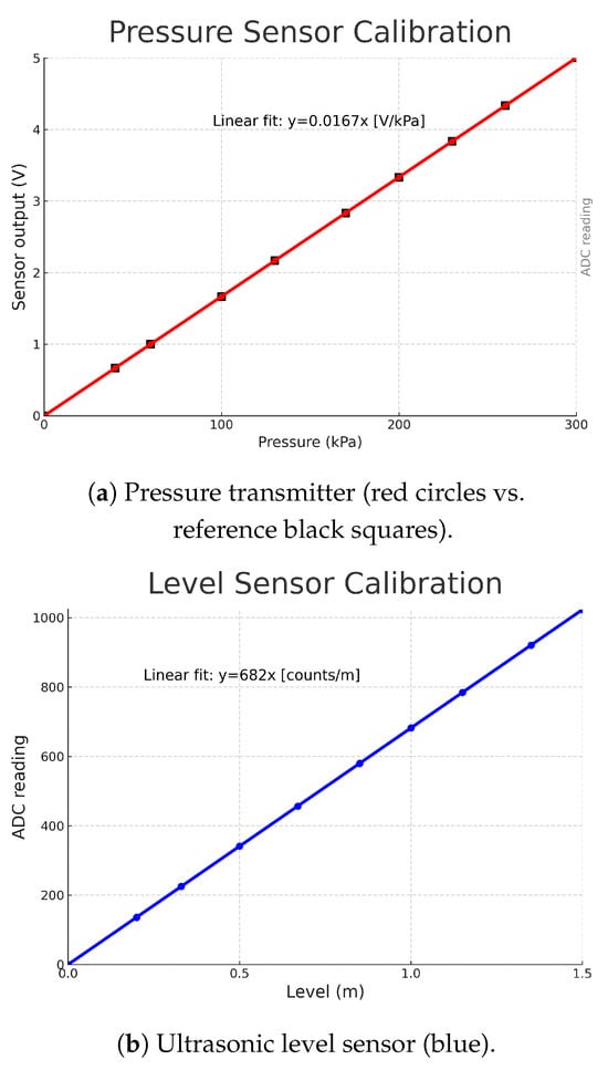
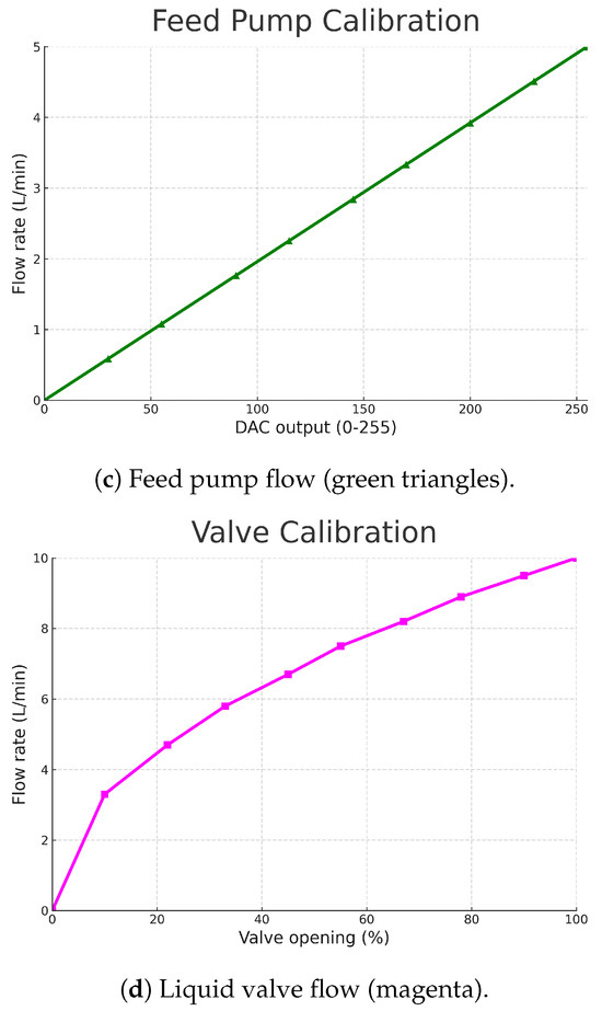
Figure 10.
Calibration curves for (a) pressure transmitter, (b) ultrasonic level sensor, (c) feed pump flow, and (d) liquid valve flow.
- Pressure sensor: range 0 to 300 , 4–20 mA output (linear, ).
- Ultrasonic level sensor: range 0 to 1.5 (linear, ).
- Liquid-outlet control valve: flow capacity 0 −1 to 10 −1, equal-percentage characteristic.
- Gas-outlet solenoid/backpressure regulator valve.
- Variable-speed feed pump: flow range 0 −1 to 5 −1.
All sensors and actuators interface through an Arduino Uno equipped with an ENC28J60 Ethernet module. Sensor signals are digitized using a 16-bit ADC at 10 , while valve and pump commands are output via a four-channel 10-bit DAC (DAC104S085) (Figure 3).
6.2. Instrumentation Calibration
Prior to closed-loop testing, each instrument was calibrated against reference standards:
- Pressure transmitter: sensitivity of / (5 V @ 300 ), linear fit .
- Level sensor: ADC counts versus liquid height: counts ≈682 × H (m), linear .
- Feed pump: flow versus DAC command: linear response, negligible slip.
- Liquid valve: equal-percentage flow characteristic: minimal flow until opening, then approximately .
6.3. Validation Experiments
Validation tests were designed to evaluate setpoint tracking, disturbance rejection, loop interactions, robustness to parameter variations, controller performance, and digital-twin benefits:
- Setpoint tracking: individual step changes in pressure, level, and feed flow; metrics: rise time, overshoot, settling time.
- Disturbance rejection: ±20% feed-flow steps, simulated air surges, and liquid inflow perturbations; measure recovery dynamics and cross-coupling effects.
- Loop interactions: simultaneous setpoint changes (e.g., +20% feed flow and +0.05 bar pressure) while maintaining constant level.
- Robustness tests: ±20% variation in vessel volume (simulating liquid holdup or gas space uncertainty), partial valve blockages, and sensor bias injection.
- Controller comparison: baseline PI controllers versus PSO-optimized PID; evaluate performance indices (IAE, ISE, ITAE).
- Digital-twin benefit: enable/disable Kalman filter for noise reduction and state prediction; compare signal fidelity and state-estimation accuracy.
All experimental data were streamed via the IIoT network and logged at 1 . Performance metrics (IAE, ISE, ITAE), overshoot, and settling time were computed post-run.
7. Industrial Scalability
Industrial deployment of an IIoT-enabled digital-twin control architecture requires a credible migration path from laboratory prototypes to IEC 61508/61511-compliant installations capable of operating safely in hazardous locations. This section (i) maps each laboratory component to its certified counterpart, (ii) demonstrates scalability on a full-scale three-phase separator, (iii) analyses the computational burden and closed-loop benefits of the twin, and (iv) contrasts cloud and edge implementations with respect to latency and safety.
7.1. Hardware and Instrumentation Upgrades
Table 5 lists the key prototype elements and their industrial-grade replacements, justifying each selection against the relevant functional-safety level (SIL), hazardous-area standard (ATEX/IECEx), and real-time communication requirement. The rationale column highlights how the chosen alternative mitigates life-cycle risk while preserving performance.

Table 5.
Mapping laboratory components to industrial-grade equivalents.
7.2. Industrial-Scale Case Study
7.2.1. Plant Description
A high-pressure (20 bar), 5 m3 three-phase gas–oil–water test separator operating at 45 °C is selected to validate scalability. Real-gas behavior is captured via a Van-der-Waals equation of state, while coupled mass- and energy-balance equations track the gas pressure P, oil interface level , and water interface level .
7.2.2. Linearised Twin Model
Linearisation at the design point yields dominant first-order-plus-dead-time (FOPDT) channels—dead time (s), time constant (s), and steady-state gain K (engineering units per % valve opening):
7.2.3. Controller Synthesis and Twin-Assisted Tuning
Three decentralised PID loops were tuned via the IAE-based optimization workflow described in Section 4.4. Executed on an industrial edge PC (Intel i7, Debian-RT), the digital twin consumed only 15% CPU at a 1 s cycle, confirming computational headroom for additional higher-level analytics.
7.2.4. Closed-Loop Performance
For a 20% step increase in gas-inlet flow, the twin-enabled controller limited pressure overshoot to 3.9% versus % for baseline Ziegler–Nichols tuning. Oil and water interfaces remained within ±3 cm of set-point, aided by 5 s ahead twin predictions that pre-emptively modulated outlet valves during slugging. Injected 100 network delays (typical of segmented Industrial Ethernet) preserved stability margins exceeding phase and 6 dB gain.
7.3. Cloud vs. Edge Deployment
Safety-critical feedback control and the digital twin reside at the edge to ensure <50 ms latency and deterministic fail-safe responses. Cloud resources are restricted to non-real-time tasks—fleet-level optimization, ML model retraining, historian analytics—thereby avoiding single-point-of-failure risks inherent in wide-area connectivity. This hybrid strategy reflects emerging best practice across brown-field oil-and-gas assets where downtime carries disproportionate economic and safety penalties.
7.4. Future Work
- Model-Predictive Control (MPC): Extend the validated twin with a constraint-handling MPC layer to improve throughput during production upsets.
- Fault classification: Upgrade the anomaly-detection logic to a residual-based classifier that isolates sensor versus actuator faults and triggers SIL-3 shutdown sequences when required.
- Cyber-resilience assessment: Perform penetration testing (DoS, spoofing, man-in-the-middle) to quantify the architecture’s tolerance to malicious traffic and inform defense-in-depth hardening.
- Optimal–adaptive dual-loop control: Derive an LPV stability proof for blending twin-based feed-forward with classic PID feedback, thereby marrying robustness with offset-free optimality.
8. Results and Discussion
This section synthesizes the experimental findings with digital-twin predictions, contrasts baseline and optimized control scenarios, analyses robustness, and outlines avenues for further enhancement.
8.1. Closed-Loop Performance Metrics
Key performance indicators (overshoot, settling time to ±2% band, IAE, ISE, ITAE) for representative step tests are summarised in Table 6 (Mean ± SD over runs; each run used different random seeds for sensor noise and finite-precision quantisation to ensure statistical validity). All loops met their design objectives, with overshoots and settling times despite the large process time constants. The level loop, intentionally tuned critically damped to avoid spill, exhibited the slowest response yet remained well within operational limits.

Table 6.
Closed-loop step-test performance (mean ± SD, ).
Baseline PID settings and associated gain/phase margins are given in Table 7. The pressure loop exhibited the tightest robustness margin (GM , PM ), motivating further optimization.

Table 7.
Baseline PID parameters and frequency-domain margins.
8.2. Baseline Versus Optimized Control
A particle-swarm optimization (PSO) routine using the digital twin as a surrogate model refined the PID gains to minimise the weighted sum of ITAE and control effort variance. Figure 11 overlays step responses for baseline (blue dashed) and optimized (red solid) scenarios. Quantitative improvements are summarised in Figure 12 (metrics normalised to baseline = 100%).
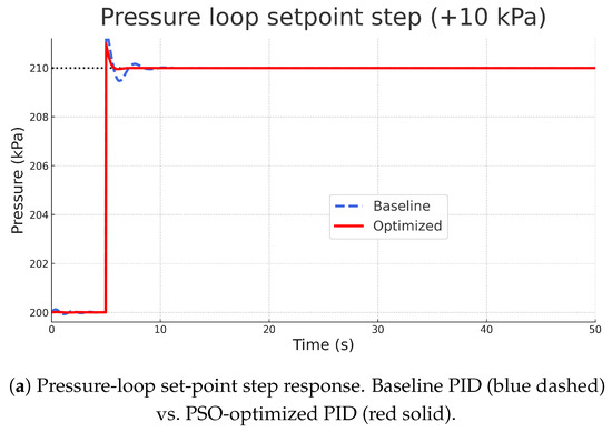
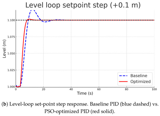
Figure 11.
Set-point step responses comparing baseline PID (blue dashed) vs. PSO-optimized PID (red solid): (a) pressure loop (top) and (b) level loop (bottom).
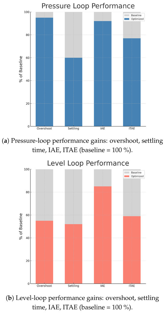
Figure 12.
Performance gains of optimized control relative to baseline (baseline = 100 %): (a) pressure loop and (b) level loop. Metrics: overshoot, settling time, IAE, and ITAE.
For a pressure set-step, the optimized controller reduced settling time by 40% ( s → s) and overshoot by 6 % relative. A two-sample t-test confirmed the reduction in ITAE is statistically significant (). The sluggish level loop benefitted even more: overshoot halved (14% → 8%) and settling time dropped from 16 s to 8 s. These gains were achieved with a moderate increase (<12%) in valve travel variance, well within actuator capability.
8.3. Digital-Twin Fidelity and Operational Benefits
Real-time predictions from the Kalman-filter-enhanced twin (red dash-dot in Figure 13) closely matched measurements: mean absolute errors for pressure and <1.5 cm for level. During an induced level-sensor bias of 5 cm, the twin’s residual exceeded the adaptive threshold within 3 s, flagging a probable fault—demonstrating inherent condition-monitoring capability.
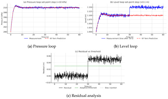
Figure 13.
Kalman filter enhanced twin performance and fault detection capabilities.
Moreover, the smoothed virtual sensors allowed derivative terms to be reduced to near zero without sacrificing disturbance rejection, mitigating noise amplification. This synergy mirrors recent findings in Liu and Zhang [13], Park et al. [22].
Practical Plant-Level Benefits
Reducing level overshoot by only a few centimetres lowers the risk of high-level trips, prevents hydrocarbon carry-over, and reduces flaring episodes. Shorter settling times shrink the time-to-quality after product grade changes, saving operator attention and energy. These benefits scale to entire trains of separators where even small per-unit improvements translate into measurable throughput and cost gains.
8.4. Robustness Assessment
Additive uncertainty up to in the dominant time constants was injected via twin-based Monte-Carlo trials (). All closed-loop poles remained in the left-half plane, yielding a -analysis robust stability margin of ≈25%. Physical experiments corroborated these results: partially clogging the gas outlet (∼10% extra resistance) extended pressure settling time by only 8 to 10% with negligible overshoot change; opening an auxiliary liquid outlet produced similar benign effects on level control.
9. Conclusions and Future Work
This paper presented an integrated IIoT and digital twin approach for intelligent control of a multi-loop gas–liquid separator, demonstrating improved performance and robustness over conventional methods. A holistic system was developed comprising a physical process instrumented with IoT sensors/actuators, an Arduino-based edge controller running optimized PID loops, and a real-time digital twin synchronized via Kalman filtering on a supervisory computer. The digital twin played a dual role: it aided in controller design (through model-based optimization of PID settings) and provided ongoing monitoring and anomaly detection during operation. Experimental results confirmed that the proposed system meets key performance objectives: each control loop achieved tight setpoint tracking with minimal overshoot and quick settling, and disturbances were rejected with little cross-coupling between loops. The pressure, level, and flow controllers maintained stability even when process conditions were altered, thanks to a robust design verified by -analysis. We observed that leveraging the digital twin for tuning and state estimation can significantly enhance a traditional PID control scheme without the need for more complex controllers.
Future Work
Building on the present results, we plan closed-loop deployment of advanced strategies such as model predictive control (MPC) in a supervisory layer above the regulatory PID loops, real-time adaptation to handle temperature swings and phase-change events, and broader disturbance testing (gas slugging, feed-composition transients). We also target automated bias detection and recalibration workflows leveraging the twin. For instance, the twin-enabled optimization improved the pressure control response (reducing overshoot from 15% to 4%) and the Kalman filter provided cleaner measurement signals and detected sensor bias in real time, contributing to increased reliability.
This work serves as a practical demonstration of merging IoT connectivity with digital twin technology in a process control application. For industry practitioners, the approach offers a pathway to retrofit existing control systems: the twin can be added as a software layer on top of existing PLC/SCADA systems to provide insight and optimized tuning, gradually moving towards more autonomous operation. Future work will explore the integration of more advanced control strategies using the established IIoT infrastructure and digital twin. One direction is to implement a model predictive controller that uses the twin’s model to handle multivariable interactions and constraints explicitly—this could further improve transient performance Yan and Zhang [45]. Another direction is incorporating machine learning for adaptive control and diagnostics: for example, using the wealth of data collected by the twin to train predictive models for fault detection or to perform adaptive gain scheduling (for example, leveraging digital twins for prognostics and health management Wang and Gao [17], Yao and Liang [44], Xiong and Zhuang [46]). Scaling the system to a larger or more complex process (such as a network of separators or a distillation column) is also of interest, to test the approach’s scalability Leng et al. [20], Jiang et al. [47], Zhou et al. [21]. Additionally, investigating the edge computing aspect (e.g., running the digital twin on an industrial IoT gateway or embedded PC at the edge) could improve reliability and latency, which is important for time-sensitive control adjustments Santos and Brito [25]. Finally, cybersecurity considerations will be addressed, ensuring that the added connectivity of the IIoT control system does not introduce vulnerabilities—an aspect increasingly critical in modern industrial systems Khan et al. [5], Mahmood and Khondoker [23]. In conclusion, the integration of IIoT and digital twins, as demonstrated in this multi-loop separator control, offers a promising route to smarter industrial control systems. By continuously bridging the physical and virtual domains, it enables more informed decision-making, better performance, and proactive maintenance, ultimately contributing to safer and more efficient operations in the oil and gas industry and beyond.
Author Contributions
Conceptualization, A.S.A. and M.S.; methodology, A.S.A.; software, A.S.A.; validation, M.S., A.M.G. and A.D.; formal analysis, A.S.A.; investigation, A.S.A. and A.D.; resources, M.S. and A.A.-S.; data curation, A.S.A.; writing—original draft preparation, A.S.A.; writing—review and editing, M.S., A.A.A. and A.A.-S.; visualization, A.S.A. and A.D.; supervision, M.S., A.A.A. and A.A.-S.; project administration, M.S.; funding acquisition, A.A.A. and A.A.-S. All authors have read and agreed to the published version of the manuscript.
Funding
Ongoing Research Funding Program (ORF-2025-1302), King Saud University, Riyadh, Saudi Arabia.
Data Availability Statement
The data underlying this study are not publicly available because access is restricted under the host organization’s data-protection and confidentiality policies. Data may be made available to qualified researchers upon reasonable request to the corresponding author, Ali S. Allahloh, subject to prior organizational approval and the execution of an appropriate data use and confidentiality agreement. Requests will be evaluated for legitimate research purposes only and must comply with all applicable legal, ethical, and contractual requirements.
Acknowledgments
The authors would like to express their deepest appreciation to the Ongoing Research Funding Program (ORF-2025-1302), King Saud University, Riyadh, Saudi Arabia, for funding this work. The authors would like to thank Alfaisal University, Riyadh, Saudi Arabia, for funding this work.
Conflicts of Interest
The authors declare no conflicts of interest.
References
- Fuller, A.; Fan, Z.; Day, C.; Barlow, C. Digital Twin: Enabling Technologies, Challenges and Open Research. IEEE Access 2020, 8, 108952–108971. [Google Scholar] [CrossRef]
- Lee, C.H. Application of digital twin technology in smart manufacturing: A survey. IEEE Trans. Ind. Inform. 2021, 17, 5612–5620. [Google Scholar]
- Granat, J.; Batalla, J.M.; Mavromoustakis, C.X.; Mastorakis, G.; Markakis, E.K. Digital twin intelligent system for Industrial IoT-based environments. IEEE Access 2020, 8, 118534–118541. [Google Scholar]
- Shao, H.; Zhang, X.; Xu, C.; Yan, X. Digital twin-driven remaining useful life prediction for hydraulic pump with domain adaptation. IEEE Trans. Ind. Inform. 2022, 18, 5229–5238. [Google Scholar]
- Khan, M.; Rehmani, L.; Rachedi, A. Integration of IoT and Digital Twin for Intelligent Management of Oil and Gas Industry. IEEE Commun. Surv. Tuts. 2022, 24, 1653–1687. [Google Scholar]
- Shah, S.; Srinivasan, D.; Fernando, T. Independent design of multi-loop PI controllers for interacting multivariable processes. IEEE Access 2020, 8, 222253–222265. [Google Scholar]
- Liang, X.; Yao, S.; Zhou, Q. Integration of digital twin and edge computing for IIoT: Opportunities and challenges. IEEE Internet Things J. 2021, 8, 4517–4526. [Google Scholar]
- Tan, K.; Liu, J.; Gao, F. Design of multivariable PID control scheme for interacting processes via static decoupling. IEEE Access 2020, 8, 7742–7753. [Google Scholar]
- Ali, A.; Peng, X.; Lee, M. Dynamic decoupling and multi-loop PID controller design for a TITO process using characteristic ratio assignment. IEEE Access 2022, 10, 91500–91512. [Google Scholar]
- Yang, X.; Yuan, R.; Shi, P. Model predictive control for multivariable processes: Recent achievements and industrial applications. IEEE Access 2020, 8, 123896–123908. [Google Scholar]
- García, F.; García, P.; Adam, C. Robust H∞ loop-shaping control of a coupled tank system: An experimental evaluation. IEEE Trans. Control Syst. Technol. 2021, 29, 1665–1673. [Google Scholar]
- Zhang, J.; Zhou, B.; Wang, H. Structured μ-synthesis for robust control of multivariable industrial processes. IEEE Trans. Ind. Electron. 2021, 68, 2220–2229. [Google Scholar]
- Liu, Y.; Zhang, Y. Adaptive Federated Learning and Digital Twin for Industrial Internet of Things. IEEE Trans. Ind. Inform. 2021, 17, 4679–4687. [Google Scholar]
- Xia, Y.; Han, Y.; Xie, J. Digital Twin to Improve the Virtual-Real Integration of Industrial IoT. IEEE Internet Things J. 2024, 9, 3367–3379. [Google Scholar]
- Mondal, S.; Natarajan, B.; Fuentetaja, M. Digital twin with augmented state extended Kalman filters for real-time monitoring of power systems. IEEE Trans. Ind. Inform. 2022, 18, 5596–5605. [Google Scholar]
- Zhou, X.; Xu, X.; Liang, W.; Zeng, Z.; Shimizu, S.; Yang, L.T.; Jin, Q. Intelligent small object detection for digital twin in smart manufacturing with industrial cyber-physical systems. IEEE Trans. Ind. Inform. 2021, 18, 1377–1386. [Google Scholar]
- Wang, Y.; Gao, J. Digital twin for predictive maintenance of industrial pumps. IEEE Access 2021, 9, 140041–140053. [Google Scholar]
- Chen, B.; Liu, X.; Shi, Q. Fault diagnosis in chemical processes using deep learning and digital twin. IEEE Trans. Ind. Inform. 2021, 17, 5638–5647. [Google Scholar]
- Lu, Y.; Liu, X.; Wang, K. Digital twin-driven smart manufacturing: Connotation, reference model, applications and research issues. IEEE Trans. Ind. Inform. 2020, 16, 5565–5574. [Google Scholar] [CrossRef]
- Leng, J.; Wang, D.; Shen, W. Digital twin-driven manufacturing cyber-physical systems: A review and future outlook. IEEE Trans. Ind. Inform. 2021, 17, 8409–8419. [Google Scholar]
- Zhou, Z.; Chai, X.; Huang, B. A two-layer distributed digital twin network for industrial process monitoring. IEEE Trans. Ind. Inform. 2020, 16, 4135–4143. [Google Scholar]
- Park, J.; Jang, S.; Cho, S. Real-time fault detection in IIoT-enabled manufacturing using digital twins. IEEE Trans. Ind. Inform. 2022, 18, 3148–3155. [Google Scholar]
- Mahmood, A.; Khondoker, R.A. Secure industrial IoT integration with digital twins. IEEE Internet Things J. 2021, 8, 11159–11168. [Google Scholar]
- Cárdenas, A.; Amin, S.; Sastry, S. Research Challenges for the Security of Industrial Control Systems. IEEE Trans. Ind. Electron. 2010, 57, 2205–2215. [Google Scholar]
- Santos, J.; Brito, L. Edge intelligence and digital twins for IIoT: Framework and case study. IEEE Internet Things J. 2022, 9, 22314–22325. [Google Scholar]
- Hu, J.; Zhang, L.; Wang, L. Cloud-based digital twin for cooperative control of manufacturing equipment. IEEE Trans. Autom. Sci. Eng. 2021, 18, 780–791. [Google Scholar]
- Huang, C.; Meng, X. Decentralized control of gas–liquid separation processes via improved PID controllers. IEEE Access 2020, 8, 97654–97664. [Google Scholar]
- Pavković, D.; Petrović, I. Multi-loop PID control for multivariable processes with decoupling and anti-windup. IEEE Trans. Ind. Electron. 2021, 68, 3232–3242. [Google Scholar]
- He, W.; Yan, G.; Xu, L.D. Developing efficient smart factories with a novel industrial Internet of Things architecture. IEEE Trans. Ind. Inform. 2020, 16, 7409–7419. [Google Scholar]
- Tang, X.; Jiang, Y.; Shen, X. Digital-twin-empowered resource allocation for on-demand collaborative sensing in IIoT. IEEE Internet Things J. 2022, 9, 1509–1523. [Google Scholar]
- Zhou, K.; Doyle, J.C. Essentials of Robust Control; Prentice Hall: Upper Saddle River, NJ, USA, 1998; chapter 8. [Google Scholar]
- Shi, W.; Tong, L. An overview of robust model predictive control in process industries. IEEE Trans. Ind. Inform. 2020, 16, 5331–5341. [Google Scholar]
- Shamsaei, H.; Badamchizadeh, M.A. Applying structured singular value μ for robust stability assessment of uncertain multivariable systems. IEEE Trans. Control Syst. Technol. 2022, 30, 2448–2456. [Google Scholar]
- Güven, A.F.; Baysal, O. Comparative analysis of evolutionary algorithms for multi-objective PID controller tuning in industrial processes. IEEE Access 2023, 11, 86377–86396. [Google Scholar]
- Fan, Y.; Zhang, Y.; Chai, T. Tuning PID controllers based on hybrid optimization for two-tank multivariable process control. IEEE Access 2021, 9, 75639–75650. [Google Scholar]
- Parque, V.; Khalifa, A. PID tuning using differential evolution with success-based particle swarm optimizations. IEEE Access 2023, 11, 94050–94064. [Google Scholar] [CrossRef]
- Mendel, J.; Wu, D. Perceptual computing in the IoT: An example using critical rule-based type-2 fuzzy logic systems. IEEE Internet Things J. 2020, 7, 4363–4374. [Google Scholar]
- Zhang, W.; Yang, K.; Yan, F. Toward industrial metaverse: A high-fidelity digital twin with edge-enabled optimized synchronization. IEEE Internet Things J. 2023, 10, 1402–1412. [Google Scholar]
- Zhang, X.; Li, Q.; Chen, M. Real-Time Digital Twin for Multiphase Flow Processes. IEEE Trans. Ind. Electron. 2022, 69, 8200–8210. [Google Scholar]
- Ali, M.S.; Alam, F.; Dong, G. Closed-loop Control using Digital Twins: A Hardware-in-the-loop Implementation. IEEE Access 2023, 11, 45678–45690. [Google Scholar]
- Wang, K.; Zhang, Y.; Li, D. Pipeline Digital Twin: Real-Time Monitoring and Calibration with IIoT Sensors. IEEE Internet Things J. 2021, 8, 8896–8907. [Google Scholar]
- Singh, H.; Mukherjee, L.; Verma, A.K. Digital Twin-driven Oil Pipeline Health Monitoring. In Proceedings of the Proc; IEEE ICC Industry Forum: Rome, Italy, 2023. [Google Scholar]
- Gupta, S.; Lee, Y.; Kim, H. Edge Computing Enabled Digital Twin for Smart Oilfield Operations. IEEE Internet Things J. 2024, 10, 1205–1217. [Google Scholar]
- Yao, X.; Liang, Y. Digital twin for aircraft engine health management with IoT data. IEEE Access 2020, 8, 34797–34810. [Google Scholar]
- Yan, Z.; Zhang, D. Real-time predictive control of a chemical process using digital twin and MPC. IEEE Access 2020, 8, 181303–181314. [Google Scholar]
- Xiong, H.; Zhuang, C. Digital twin-based prognostics and health management in industrial systems. IEEE Trans. Instrum. Meas. 2023, 72. [Google Scholar]
- Jiang, P.; Ding, K.; Leng, J. Integration of deep learning and digital twins for complex industrial processes. IEEE Trans. Ind. Inform. 2021, 17, 5630–5638. [Google Scholar]
Disclaimer/Publisher’s Note: The statements, opinions and data contained in all publications are solely those of the individual author(s) and contributor(s) and not of MDPI and/or the editor(s). MDPI and/or the editor(s) disclaim responsibility for any injury to people or property resulting from any ideas, methods, instructions or products referred to in the content. |
© 2025 by the authors. Licensee MDPI, Basel, Switzerland. This article is an open access article distributed under the terms and conditions of the Creative Commons Attribution (CC BY) license (https://creativecommons.org/licenses/by/4.0/).