Article

Virtual Prototyping of the Human–Robot Ecosystem for Multiphysics Simulation of Upper Limb Motion Assistance †

Department of Mechanical, Energy, and Management Engineering, University of Calabria, 87036 Rende, Italy
*
Author to whom correspondence should be addressed.
This article is a revised and expanded version of a paper entitled “Application of a multibody approach for the Digital Twinning of the human-robot ecosystem in upper limb rehabilitation”, which was presented at the Fifth International Conference of IFToMM ITALY 2024, Torino, Italy, 11–13 September 2024.
Machines 2025, 13(10), 895; https://doi.org/10.3390/machines13100895
Submission received: 24 July 2025 / Revised: 17 September 2025 / Accepted: 25 September 2025 / Published: 1 October 2025

Abstract

As stroke is becoming more frequent nowadays, cutting edge rehabilitation approaches are required to recover upper limb functionalities and to support patients during daily activities. Recently, focus has moved to robotic rehabilitation; however, therapeutic devices are still highly expensive, making rehabilitation not easily affordable. Moreover, devices are not easily accepted by patients, who can refuse to use them due to not feeling comfortable. The presented work proposes the exploitation of a virtual prototype of the human–robot ecosystem for the study and analysis of patient–robot interactions, enabling their simulation-based investigation in multiple scenarios. For the accomplishment of this task, the Dynamics of Multi-physical Systems platform, previously presented by the authors, is further developed to enable the integration of biomechanical models of the human body with mechatronics models of robotic devices for motion assistance, as well as with PID-based control strategies. The work begins with (1) a description of the background; hence, the current state of the art and purpose of the study; (2) the platform is then presented and the system is formalized, first from a general side and then (3) in the application-specific scenario. (4) The use case is described, presenting a controlled gym weightlifting exercise supported by an exoskeleton and the results are analyzed in a final paragraph (5).

1. Introduction

Upper extremity impairment is one of the multiple consequences of stroke, which presents in the form of muscle weakness, reduced control, and strength on the hemiparetic side of the body [1,2]. The upper extremity being among the most operative parts of the body [3], the daily life of patients is significantly affected. Subjects lose their independence, and poststroke impairment also becomes an obstacle from a social perspective, hindering their ability to perform Activities of Daily Living (ADLs) [1,4,5,6,7]. However, some of these capabilities can be recovered through a proper rehabilitative path [8]. Though conventional therapy has proved effective, it does not always represent the best solution, due to the reduced number of therapists and means [9]. For this reason, focus has recently moved to robotic rehabilitation, which is able to improve motor functions and neuroplasticity through the active involvement of the patients [10,11]. Many rehabilitative robots have already been developed, reducing the physical effort required by therapists [1] and providing intensive, repetitive, and task-specific tasks to the patients [12]. Based on structure, they can be divided in two categories: end-effectors and exoskeletons. End-effectors distally control the arm and they are easier to develop, since they do not need to adapt to the structure of the whole upper limb. It becomes difficult, however, to monitor what happens far from the robot, being that the posture is not constrained and torque control on specific joints is not possible [6]. Exoskeletons, on the contrary, are built to follow the physiognomy of the upper limb, completely encapsulating it [13], making them subject-specific. Neglecting the hand structure, the human upper limb has nine DoFs: five coming from the shoulder, two from the elbow, and two from the wrist and most exoskeletons have indeed focused on movements of these joints [6]. During the tasks, the exoskeleton can be passive, hence moved by the subject or active, hence actuated. Upper-limb rehabilitation devices rely on a variety of actuators, ranging from conventional electric motors to pneumatic and hydraulic systems, as well as more recent solutions such as pneumatic artificial muscles (PMA), twisted and coiled artificial muscles (TCAM), and shape-memory alloys (SMA) [14]. Electric motors are reliable and precise but they can add bulk and weight; pneumatic and hydraulic actuators provide high power but often require complex infrastructures and control systems; soft actuators like SMA and TCAM are compact, yet limited by slower response times and efficiency. Designing an effective robotic exoskeleton therefore means balancing these trade-offs carefully. In this process, simulations make it possible to explore and compare the behavior of different actuators under realistic conditions before moving to physical prototypes. Developing multiphysical simulation platforms is particularly promising, as these tools allow not only the modeling of individual technologies but also the study of how different actuation principles might be combined. Such hybrid approaches open the door to systems that are more adaptable, energy-efficient, and accessible, while maintaining the safety and usability required in rehabilitation settings [15,16]. The complexity of the structure, its specificity to the patient and the high quantity of required sensors makes these devices extremely expensive, hence hardly affordable. To this end, the proposed work aims at contributing to create a path towards a more accessible rehabilitation robotics. Recently, Adduci and Mundo [17] presented a novel methodology for indirect muscle force estimation based on biomechanical multibody models. The proposed approach is based on the use of a dedicated multiphysics simulation platform, namely the DMS platform, for which a benchmark against third-party software, i.e., OpenSim, is also provided. The main contribution of the present paper is an extension of the simulation capabilities of the proposed platform, which integrates biomechanical models of the human body with mechatronics models of robotic devices for motion assistance, as well as with a PID-based control strategy. The present paper proposes the use of a single-DoF cable-driven exoskeleton in a simulation environment, composed of the virtual prototype of the device with its multibody (MB) model and of the upper limb with the respective biomechanical model. The purpose is to create an optimized simulation-based design to ease the patient’s introduction to the rehabilitative device. The proposed task emulates the accomplishment of a typical gym weightlifting exercise by means of robotic assistance. The application is developed by exploiting the proposed DMS (Dynamics of Multi-physical Systems) platform, which makes available a multi-physical space involving various domains of interest, all in a simulation environment. In this specific application, the concept is that of simulating the same exercise for different subjects’ conditions, healthy and poststroke with decreased levels of muscle activations, which is what occurs due to disease. Robotic assistance is necessary, since it is supposed that poststroke patients are not able to complete the task independently. In this regard, a torque control is implemented through a PID which, starting from the error on the position, provides the necessary effort to reach the desired angle.
The presented work presents a virtual prototyping framework for human–robot ecosystem simulation in upper limb rehabilitation. Building upon the previously published DMS platform [17], this work introduces novel extensions for human–robot interaction modeling. The primary novelty of the contribution lies in creating the first integrated virtual prototyping environment for complete human–robot ecosystem simulation, enabling patient-specific analysis and exoskeleton/control design optimization prior to physical prototyping, a foundational step toward comprehensive digital twin systems for rehabilitation robotics. Section 2 presents the DMS platform architecture, describing the established multiphysics simulation framework that serves as the foundation for this work. Section 3 presents the model elements, introducing the Thelen-based muscle model architecture, cable-driven exoskeleton modeling, and novel implementations of integrated control strategies within a DAE framework. Section 4 describes the first comprehensive virtual prototype of a human–exoskeleton ecosystem through four simulation scenarios, ranging from healthy to impaired patients with varying assistance levels. Section 5 presents quantitative analysis of human–robot interactions, demonstrating joint loading assessment, controller adaptation patterns, and biomechanical stress evaluation across different patient capabilities. The manuscript concludes in Section 6 where the main takeaways are discussed.

2. The DMS Platform

The Dynamics of Multi-physical Systems platform is a powerful tool combining mechanical, biomechanical, electrical, and control domains in a unique simulation framework able to model and study various problems and systems in an object-oriented Matlab 2015 environment. In this section, a detailed description of the key ingredients used to construct the DMS platform is described.
In particular, Section 2.1 describes the architectural composition and functional capabilities of the DMS platform, while a general mathematical insight is given in Section 2.2. Section 2.3 and Section 2.4 proceed with the description of the solution methods and model-based sensors, respectively.

2.1. The Multiphysics Platform Architecture

The DMS platform is built upon a robust MultiBody (MB) formulation that provides a powerful mathematical foundation for representing complex and multi-domain physical systems. The different domains are combined by means of a unique and coupled mathematical description that leverages the structure of Differential Algebraic Equations (DAEs) typical of constrained MB systems [18], enabling the platform to effectively handle complex physical phenomena. The advantage of this way of modeling is that every step of the study is faced in the same way, from the discretization of time to the control system states, making it easier to analyze the overall space while maintaining numerical stability and accuracy across different simulation domains. The versatility of the platform allows the creation of virtual prototypes for a wide range of fields and applications, analyzing the kinematics, statics, and dynamics of the systems, having any model-related information easily at hand, making the space suitable for Virtual Sensing, currently based on the Kalman filter [17]. In this regard, sensitivities information of the multiphysics models can be analytically and straightforwardly computed for gradient-based applications thanks to the full access and customization of the source code, leading to more accurate and time-efficient solutions compared to other possible solutions [19].
The platform represents an advanced analytical system with dual operational capabilities, as illustrated in the architecture diagram of Figure 1. The platform’s architecture is structured into two complementary functional branches that operate synergistically to provide comprehensive system analysis.
The simulation branch incorporates multiple scenarios, encompassing static simulations for steady-state analysis and kinematic/dynamic simulations for time-variant behavior assessment. This simulation framework enables users to generate precise virtual representations of physical assets across various operational conditions and domains.
The estimation branch implements novel analytical techniques, notably Kalman filtering for optimal state estimation in environments with measurement noise [17,20]. Additionally, it integrates measurement functionality for data acquisition and implements observability analysis to evaluate system stability and invertibility during indirect signal reconstruction processes.
With particular focus to the dynamic simulation framework, schematized in Figure 2, it constitutes a critical component of the DMS platform architecture. This simulation branch implements multiple objects, with emphasis on dynamic simulations for time-variant behavior analysis of complex nonlinear systems.
Operating synergistically with the estimation branch, which utilizes Kalman filtering and advanced analytical techniques, the dynamic simulation framework enables comprehensive system monitoring, predictive and early stage verification capabilities. These integrations facilitate both predictive simulation of system behavior and concurrent processing of empirical measurements, resulting in robust state estimation under variable operational conditions.
In Figure 3, the model branch of the DMS platform exhibits a hierarchical structure comprising three fundamental elements: bodies, forces, and constraints, inherited from the original MB architecture.
The generic body component incorporates various physical entity representations: point mass models for simplified mass concentration analysis, rigid bodies for non-deformable object simulation, and flexible bodies that account for material deformation. This multi-tiered approach facilitates the modeling of physical entities across a wide spectrum of complexity levels.
The force component implements multiple force representation methodologies, including: lumped loads for concentrated force applications, distributed loads for forces acting across surfaces or volumes of deformable bodies, Lumped Parameter (LP) force elements (e.g., massless and lumped flexibilities of connection elements), contact elements for modeling interaction phenomena between physical bodies, and generic model equations such as second Order Differential Equations (ODEs). This comprehensive force taxonomy enables precise simulation of complex physical interactions and components.
The constraints branch governs kinematics and mathematical restrictions within the model through two distinct categories: intrabody constraints that establish relationships within individual bodies, and interbody constraints that define interactions between separate physical entities. This constraint framework ensures simulations conform to physical laws and boundary conditions.
All three primary components incorporate extensibility mechanisms indicating the architecture’s capacity for additional modeling capabilities beyond those explicitly represented.

2.2. The Multiphysics Model Equations

Multibody dynamics is the baseline method used in this contribution to deal with complex systems comprising different application domains. As these systems are composed of various bodies, elements, and connections, they are complicated to analyze. A multibody approach makes it possible to study and monitor the behavior of the entire system, understanding how each component has its own impact on the complete and coupled scenario.
At its core, the platform leverages Differential Algebraic Equations (DAEs) as its general mathematical structure, enabling the modeling and simulation of systems with both differential and algebraic constraints. This formulation allows the platform to effectively handle the complex interactions between domains, physical bodies, forces, and constraints that characterize real-world applications.
The different domains can be represented by the following generalized coordinates q R n q :
q = [ q m T q b m T q e m T q c T q d T ] T ,
composed by representations of the mechanical ( q m ), bio-mechanical ( q b m ), electro-mechanical ( q e m ), and the control ( q c ) generalized coordinates, respectively. q d instead represents any other domain possible to model.
Introducing the generalized velocity vector v R n q and assembling the constrained system, the following set of 2 n q + 2 n ϕ implicit DAEs are obtained in the stabilized index-2 residual form [18,21]:
g = v q ˙ ϕ ( q ) q T μ = 0 n q M ( q ) v ˙ + ϕ ( q ) q T λ f n l ( q , v , u ) = 0 n q ϕ ( q ) = 0 n ϕ ϕ ( q ) q v = 0 n ϕ .
In the latter q ˙ and v ˙ R n q represent the first time derivative of q and v, respectively; λ and μ R n ϕ are the two sets of Lagrange multipliers introduced to deal with the constrained nature of the problem; ϕ ( q ) R n ϕ are the holonomic constraint equations; ϕ ( q ) q R n ϕ × n q is the constraint Jacobian; M ( q ) R n q × n q is the block diagonal configuration-dependent mass matrix of the assembled system; f n l R n q is the non-linear generalized force vector expressed as:
f n l ( q , v , u ) = f v ( q , v ) + f g ( q ) + f τ ( q , u τ ) + f ρ ( q , u ρ ) + f e x t ( q ) .
with u R n u being the generalized input vector,
u = [ u ρ T u τ T u ψ T ] T ,
composed by the muscular ( u ρ ), constraint ( u ψ ), and control ( u τ ) inputs, respectively. Moreover, f v R n q is the quadratic velocity term related to the gyroscopic forces; f ρ R n q is the generalized external force vector that includes the muscle efforts; f g R n q is the generalized gravitational force vector; f ρ R n q is the generalized control force vector; while, f e x t ( q ) R n q accounts for any other external force element that can be represented in DAE form.

2.3. Newton–Raphson-Based Solver

Once the system equations are defined, the resulting DAEs of the DMS platform are efficiently and accurately solved by means of an implicit solver with a variable time step implementation, meaning that the time step adapts to the number of iterations from previous steps depending on the system dynamics [22]. In this specific application, equations are discretized using a Backward Euler Differential Formula of order 2, chosen for its straightforward implementation and stability [23]. This choice does not imply that other differentiation schemes cannot be applied to discretize the Equations Of Motion (EOMs) in time.
For each time instance k, the solution of the system equations is required and computed, exploiting a line-search root finder based on the Newton–Raphson scheme known for its fast convergence rate. The method starts with initial guesses on the root value and continuously iterates to adjust and improve the result, exploiting the analytical gradients of the system equations.

2.4. MB-Based Sensors

From the solution of Equation (2), any quantifiable physical property can be virtually measured and described through system variables and external inputs as:
y = y 1 y j y n y T = h ( q , q ˙ , q ¨ , λ , μ , u ) ,
to represent model-based sensors, where y R n y is the vector of modeled sensors, with n y being the number of considered sensors.
Each j t h sensor model is identified by the sensor equation y j and the respective sensitivities regarding the multibody system variable, i.e., the generalized coordinates, velocity, acceleration, Lagrange multipliers, and external inputs expressed as:
y q = y q ; y q ˙ = y q ˙ ; y q ¨ = y q ¨ ; y λ , μ = y λ , μ ; y u = y u ,
and can be implied for sensitivity analysis, optimization or gradient-based estimation routines including the Kalman filter [20,24].
Since a measurement is, by definition, expressed with comparison to a standard reference, in the proposed formulation, the sensor equations define, likewise, the evolution of relative quantities that are expressed with respect to predefined coordinate systems.

3. The Adopted Model Elements

The DMS platform integrates diverse elements that capture and model complex multi-physical phenomena within a unified computational environment as schematized in Figure 3.
This section presents the modeling choices for addressing the challenges associated with dynamic modeling across various physical domains. In particular, Section 3.1 introduces the fundamental concepts of bodies and coordinates definition; Section 3.2 discusses constraint formulation and implementation; Section 3.3 examines the mathematical modeling of idealized cables; Section 3.4 details the bio-mechanical muscle elements; and Section 3.5 explores the control elements essential for system regulation and response.

3.1. Bodies and Coordinates Definition

In the present contribution, the skeletal components of the upper extremity as well as the mechanical parts of the exoskeleton are expressed by rigid bodies, interconnected by kinematic relations (constraints) and actuated through muscle and cable elements (forces).
A generic MB system can be represented by two main sets of coordinates: the minimal (independent) coordinates and the redundant (dependent) coordinates. The first set represents the easiest option with a reduced number of variables. (The independent setThe independent set of generalized coordinates describes the system motion by involving a minimal set of variables that coincide with the number of degrees of freedom of the system motion. It doesn’t require any constraint equation leading to an ordinary differential form of the dynamic equations of motion. The resulting ODE are well known to be more efficiently solvable compared to the algebraic differential equations typical of constrained systems.) However, this does not always lead to the best solution for generic multi-physical systems, especially in closed-chain mechanisms. On the other hand, the redundant set of coordinates is commonly chosen for general purpose analysis, allowing unequivocal definition of the position and orientation of all bodies of the assembled mechanical systems [25]. Nevertheless, the mathematical modeling of MB systems with the above-mentioned solution is more demanding, requiring additional inter-relational equations (algebraic constraint equations).
For the configuration of each generic b-body, the DMS platform adopts a redundant set of coordinates, three position (Cartesian) coordinates q b , p R 3 and four Euler parameters (quaternions) q b , r R 4 , also referred to as the generalized body coordinates q b R 7 :
q b = [ q b , p q b , r ]

3.2. Constraints Definition

In multibody applications, we can distinguish two types of constraint equations: the intrabody constraint equations coming from the coordinates formulations ϕ q ( q ) R n ϕ q and the interbody constraint equations ϕ g ( q ) R n ϕ g coming from the kinematic relations and also known as geometrical constraints. Together, they can be mathematically described as a set of constraint equations ϕ ( q ) R n ϕ defined as:
ϕ ( q ) = ϕ q ( q ) ϕ g ( q ) = 0 ,
with n ϕ = n ϕ q + n ϕ g .
In the current work, Equation (8) is composed only by holonomic constraint equations, but in general it might not be the case for all interbody constraints such as for constrained contact problems.
The intrabody constraints represent the bonds among degrees of freedom:
ϕ q = q b , r T q b , r 1 = 0
whereas interbody constraints define relations among joints. A simple example is here reported regarding the definition of a spherical joint defined between two bodies, a body 1 ( b = 1 ) and a body 2 ( b = 2 ), leading to:
ϕ g = q 1 , p T q 2 , p = 0
Another type of constraint involved for the proposed application is used to model part of the gym equipment. In the scenarios, a cable is attached to two pulleys for the weight lifting and it is imposed that its length configuration-dependent l ψ remains fixed ( ψ ) during the exercise. It reads as:
ϕ g = l ψ ( q ) ψ = 0

3.3. Rope/Cable Modeling

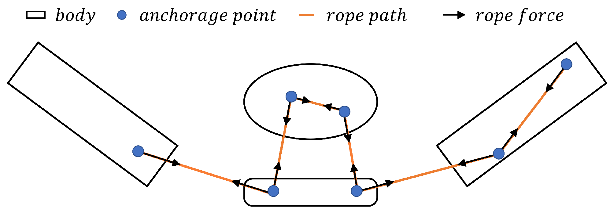
Concerning the representation of cable elements driving the exoskeleton, an idealized rope model has been adopted for each rope r. It consists of a scalar tension force τ r R + transferred among segments via n i anchorage points rigidly attached to bodies as schematized in Figure 4.
From an MB perspective, each i t h anchorage point is defined as an attachment frame through which the rope force is applied to the related body. Defining n c rope/cable elements, possibly passing through the same anchorage points, the rope force f τ , i R 3 acting on the i t h attachment frame can be computed as:
f τ , i ( q , τ ) = c = 1 n c β c , i ( q ) τ c ,
where β c , i R 3 is the configuration-dependent unit direction vector resulting from the minimal distance between two consecutive attachment frames. Finally, the resulting generalized external force vector f τ of the assembled system is obtained as:
f τ ( q , τ ) = i = 1 n i Π i ( q ) f τ , i ( q , τ ) .
Here, Π i R n q × 3 is the projection matrix that maps the forces acting onto the i t h attachment frame to the generalized coordinates, while τ = τ 1 τ n c T combines all input rope efforts.

3.4. The Bio-Mechanical Muscle Element

The muscle elements are represented in the DMS platform by means of the geometrical model similarly defined as for the rope/cable model described in the previous section. For n m number of muscle elements we obtain:
f ρ , i ( q , ρ ) = m = 1 n m β m , i ( q ) ρ m ,
and the resulting generalized external force vector f ρ of the assembled system is obtained as:
f ρ ( q , ρ ) = i = 1 n i Π i ( q ) f ρ , i ( q , ρ ) .
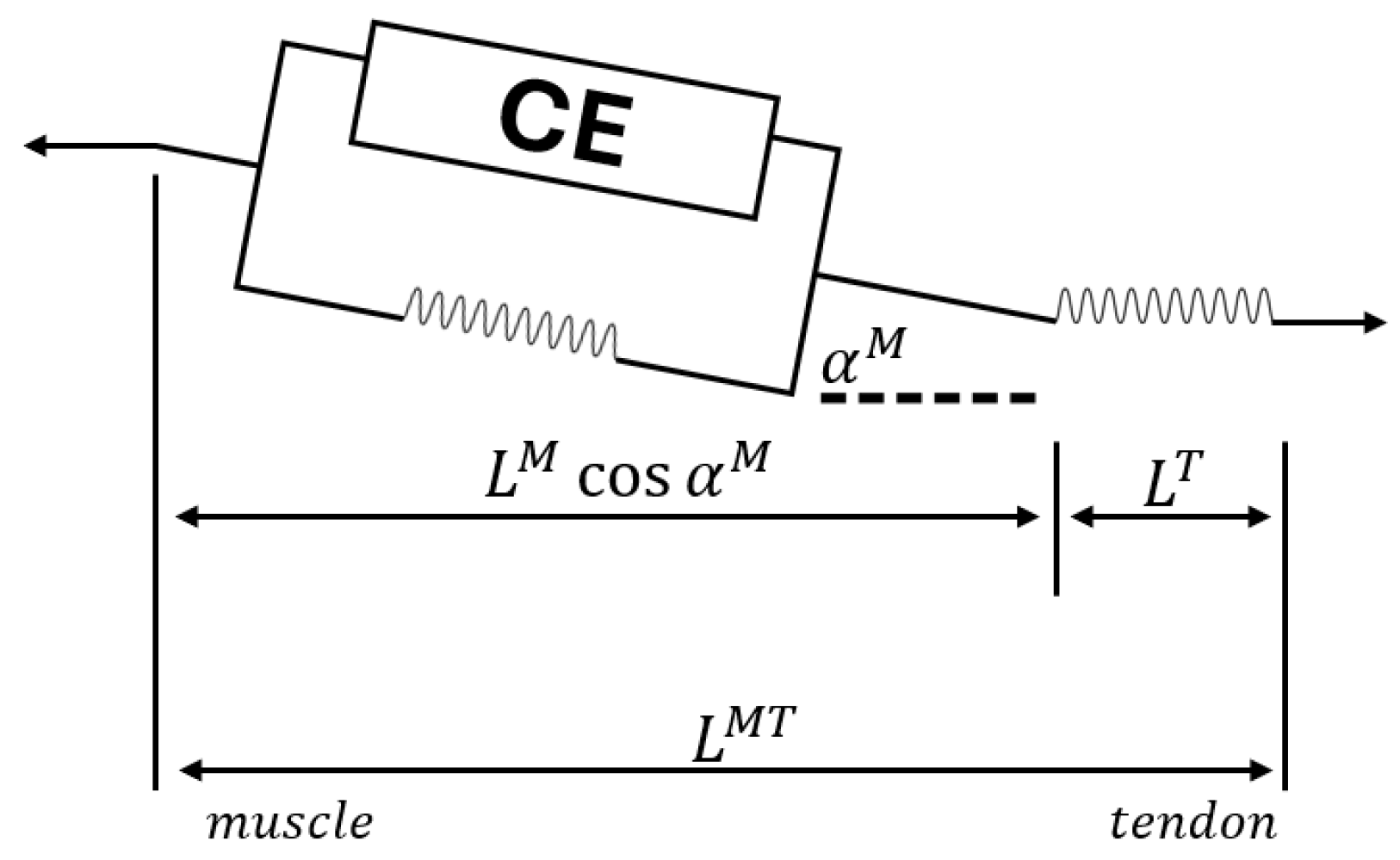
Concerning the muscle effort ρ , it is modelled as state-dependent constitutive force based on Hill’s description [26] and represented in Figure 5.
Here, the muscle consists of a contractile element (CE), a parallel element (PE) and a series element (SE) representing the tendon [27].
The overall muscles and forces generated depend on the activation value a, length ( L M ), and velocity ( V M ) of the muscle. These are driven by contraction muscle dynamics:
ρ = ρ ρ ¯ a + ρ ¯ p ,
where ρ is the muscle fiber force vector, ρ is the maximum isometric muscle force vector, ρ ¯ a is the normalized active muscle force vector, ρ ¯ p is the normalized passive muscle force vector.
The resulting active normalized muscle force can be expressed as
ρ ¯ a = a ρ ¯ a l ρ ¯ a v
where a is the muscle activation, ρ ¯ a l is the normalized force-length contribution, ρ ¯ a v is the normalized force-velocity contribution.
Concerning the muscle–tendon equilibrium, it can be expressed as force equilibrium along a common application line:
ρ cos ( α ) σ = 0
σ is the tendon force and α is the pennation angle.
Considering a fixed volume geometrical muscle model, the pennation angle is computed as:
α m = arcsin ( h m / q m )
q m is the muscle length that is an augmented variable defined by the muscle–tendon equilibrium while h m is the muscle height.
Finally, the force–length and force–velocity relations are represented in this contribution by means of the Thelen models [27].

3.5. Ropes Control Strategy

To control the forces provided by the agonistic and antagonistic ropes of the exoskeleton, two PID controllers were used. The Proportional-Integral-Derivative (PID) controller remains one of the most prevalent and reliable control strategies in robotics [28]. By combining proportional, integral, and derivative actions, the PID controller provides a robust mechanism for managing the dynamic behaviour of robotic systems, ensuring both stability and accuracy in their responses.
The proportional term generates a control signal directly proportional to the current error, defined as the difference between the desired setpoint and the actual system output. This immediate response helps reduce the error in real time. The integral term accumulates the error over time, effectively eliminating steady-state errors by addressing biases or persistent deviations. Meanwhile, the derivative term, by considering the rate of change of the error, introduces a predictive damping effect that helps mitigate overshoot and oscillations [29].
The synergy of these three components enables PID controllers to adapt to a wide variety of dynamic scenarios encountered in robotic systems. For the aim of this work, the PIDs are used to allow the robotic arm to follow a predefined trajectory. The error vector was defined as follows:
e ( q m , t ) = ψ ( t ) θ ( q m ) ,
where e is the PID error vector, θ represents the virtual angular sensor values of the exoskeleton, and ψ is the reference signal vector to be tracked.
The resulting PID action is represented by the linear tension τ applied to the agonistic or antagonistic ropes. This linear tension generates a scalar torque at the revolute joint of the elbow and is defined as:
τ = k i e , d t + k p e + k d d e d t ,
where the three terms represent the integral, proportional, and derivative actions, with control constants k i , k p , and k d , respectively.
Typically, Equation (21) is locally solved in a time-discrete form by evaluating two or more consecutive time stamps. However, in multibody (MB) applications with implicit solvers, back-and-forth evaluation can be nontrivial when using variable time-step solvers and may be computationally expensive. In this work, Equation (21) is jointly solved with the equations of motion (EOMs) in Equation (2), introducing a control variable q c and augmenting the system with an additional set of differential equations.
Computing the full differential of Equation (20) yields:
d e = d ψ d t d t θ q m d q m ,
and dividing by d t , we obtain:
d e d t = d ψ d t θ q m d q m d t = q ¨ c ,
where q c denotes the generalized coordinates associated with the control variables.
Rewriting Equation (23) and moving all terms to the left-hand side, we obtain:
q ¨ c ψ ˙ + θ q m q ˙ m = 0 ,
representing the additional set of differential equations to be solved.
Finally, substituting e = q ˙ c into Equation (21) yields:
τ = k i q c + k p q ˙ c + k d q ¨ c .
It can be observed from Equation (24) and Equation (25) that, despite the system augmentation, the resulting equations are straightforward to evaluate and solve.

PID Tuning

Achieving optimal performance requires careful tuning of the controller’s proportional ( K p ), integral ( K i ), and derivative ( K d ) gains. For tuning the proposed cable-driven robot actuators for elbow flexion–extension assistance, the Ziegler–Nichols tuning method was employed to calibrate the PID controllers governing both the agonistic and antagonistic actuators [30]. The controllers were assumed to share identical gain constants.
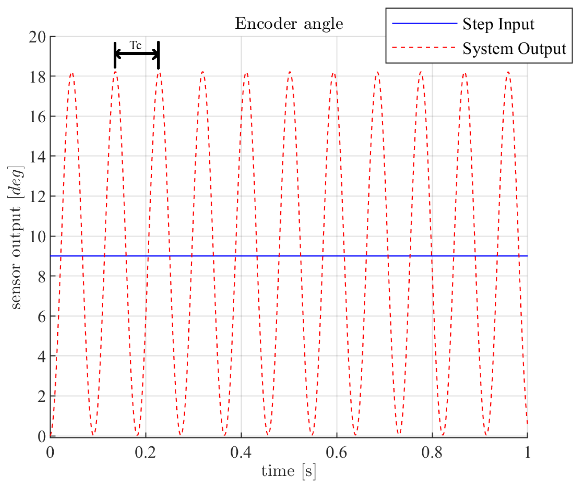
Initially, each controller was set to operate in proportional-only mode by setting the integral and derivative gains to zero. A step input of nine degrees was applied to the system. This input amplitude was empirically defined to overcome system noise and avoid actuator saturation.
Once the input was defined and with integral and derivative terms disabled, K p was gradually increased until the system reached a state of sustained, stable oscillation, as shown in Figure 6.
At this critical point, the gain was recorded as the critical gain K c , and the oscillation period was noted as the critical period T c . These values were used to compute the full PID gains according to the classical Ziegler–Nichols rules:
K p = 0.6 · K c
K i = K p 0.5 · T c
K d = K p · 0.125 · T c
This tuning process was applied independently to the agonistic and antagonistic controllers to ensure balanced and synchronized control.
The PID controller was ultimately governed by the following gain values:
K c = 9 · 10 6
T c = 0.091 s
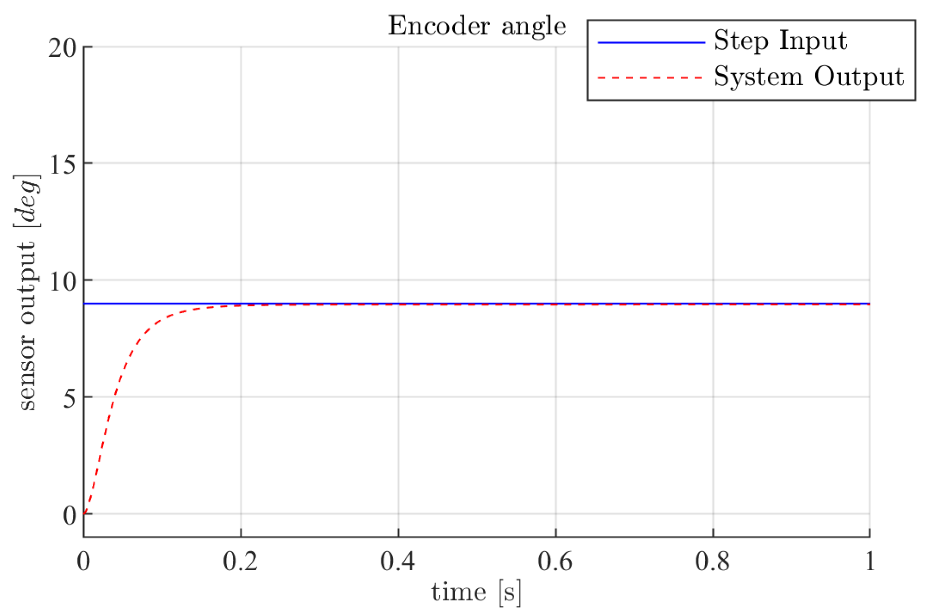
As some overshoot remained in the system response using the canonical Ziegler–Nichols configuration, a manual fine-tuning was performed by reducing the integral gain by a factor of 500. This gain adjustment resulted in the stable response illustrated in Figure 7.
The final outcome was a dynamic control scheme capable of emulating muscle-like behavior, with two actuators working as agonistic and antagonistic tensioning devices. This configuration enables smooth trajectory tracking as further demonstrated in the next section.

4. Use Cases

Defined the theoretical background and the applied methodologies, the above formulation is applied to the presented complex bio-mechanical system, studying the behavior of the upper limb undergoing a controlled gym weightlifting exercise with the assistance of an exoskeleton.
In this section the adopted model architecture is described in Section 4.1, while in Section 4.2 the analyzed simulation scenarios are presented.

4.1. Model Description

Most soft upper-limb exoskeletons in the literature actuate a single degree of freedom [31], typically at the elbow or shoulder, to investigate control strategies and evaluate user interaction without introducing the higher complexity of multi-joint models. In this work, the use of a single-DoF cable-driven exoskeleton was chosen as an initial step to validate the DMS platform in terms of actuation principles, control strategies, and the modeling of human–exoskeleton interaction. From a mechanical point of view, the scenarios consist of three subsystems, as shown in Figure 8:
The subject submodel is created using three rigid bodies representing: torso, connected to the ground through a fixed joint; humerus, attached to the torso through a fixed joint; forearm, linked to the forearm through a revolute joint to allow elbow motion. The forearm comprises, in turn, radius, ulna, and hand, rigidly connected through a fixed joint. Six muscles passing through the bodies by means of attachment points actuate the upper limb.
The exoskeleton subsystem is composed of upper and lower links connected in correspondence of the elbow through a revolute joint, comprising an angular sensor measuring the relative motion between the two bodies. The actuation of the exoskeleton is obtained using two cables.
In the proposed simulation scenario, the coupling between the exoskeleton and the human arm is considered fully rigid. However, the modularity of the DMS platform makes it possible to integrate, in future developments, a dynamic contact model at the anchoring points to support the design of adaptive fixing systems [32] that adjust the pressure on the human arm according to the user’s anatomy and required movements, thereby enhancing comfort, reducing undesired relative motion, and ultimately optimizing the transmission efficiency of the assistive forces exerted by the exoskeleton. With regard to the gym equipment, it is defined by a weight and a handle to lift it. The handle and weight bodies are connected by means of a massless, fixed-length cable that runs through two anchorage points (idealized pulleys) whereas the weight motion is allowed along the y-axis through a slider joint preventing the weight from swinging.
Finally, the upper exoskeleton-subject, lower exoskeleton-subject, and subject-gym equipment subsystems are connected by three idealized joints, respectively: fixed, between upper link of the exoskeleton and humerus; guide, between lower link of the exoskeleton and forearm to allow the sliding of the exoskeleton on the arm; and revolute, between handle and hand. While these may seem like oversimplified connections, without additional information, idealized joints provide the best modeling option for an initial evaluation analysis of the human–exoskeleton interactions.
Although the proposed model presents a single-DoF upper-limb exoskeleton, the DMS platform is designed to be fully generalizable thanks to its modular structure. This modularity enables the modeling of different types of constraints, joints, actuators, and musculoskeletal subsystems, allowing the framework to be extended beyond the presented case study. In fact, the design of exoskeletons depends on the differences in biomechanical variables such as body weight and limb dimensions. Heavier patients demand stronger structural elements together with higher actuator torques, which lead to adjustments in actuator sizing and material selection. The modular structure of the proposed DMS platform enables users to incorporate variations through the modification of anthropometric and biomechanical parameters in simulation. The platform also enables users to develop and analyze the dynamic arm-fixing mechanism that applies or reduces pressure on human arms throughout actuator and rest periods, thus improving exoskeleton long-term usability [33]. The DMS platform enables exoskeleton designs that meet different user requirements through its ability to predict how body weight changes impact joint loads, actuator requirements, and overall ergonomic design.

4.2. Analyzed Simulation Scenarios

The presented multibody model has been applied to four different scenarios, to assess its suitability to various conditions. The tests are based on the accomplishment of a gym weightlifting exercise, where an exoskeleton supporting the upper limb can intervene and provide proper assistance in case the subject is not able to complete the task. The analyzed scenarios are designed as follows:
  • Scenario 1: the subject has to actively lift a weight of 1 kg and the exoskeleton is only used as measurement device;
  • Scenario 2: as opposed to scenario 1, the exercise is now accomplished passively; no muscles intervene and the task is carried out by the exoskeleton;
  • Scenario 3: assuming that the patient is subject to an impairment that reduced his/her maximum muscular activation to 50 % , subject and exoskeleton cooperate to complete the exercise and the latter mediates in case of the patient’s inability;
  • Scenario 4: in this case, the patient can again reach maximum values of activation, but the exoskeleton assistance is still present, since the weight to lift is increased to 10 kg.

5. Results and Analysis

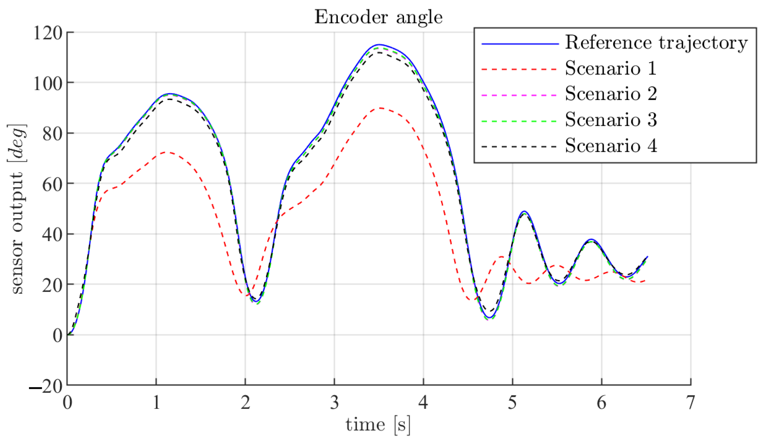
The following figures report results obtained after the execution of a gym exercise, for the four scenarios, where the exoskeleton assists or not, based on the case, in the movement of elbow flexion–extension. Figure 9 shows the trajectories tracked in the four cases:
As can be noticed, the PID controllers implied in scenarios 2 to 4, are able to follow the reference trajectory. Scenario 1, on the contrary, sees only the use of the unassisted upper limb showing a slightly detached trajectory. This may indicate that, even in a healthy scenario, the exercise is tough for the subject and light assistance from the exoskeleton could help in reaching an improved result.
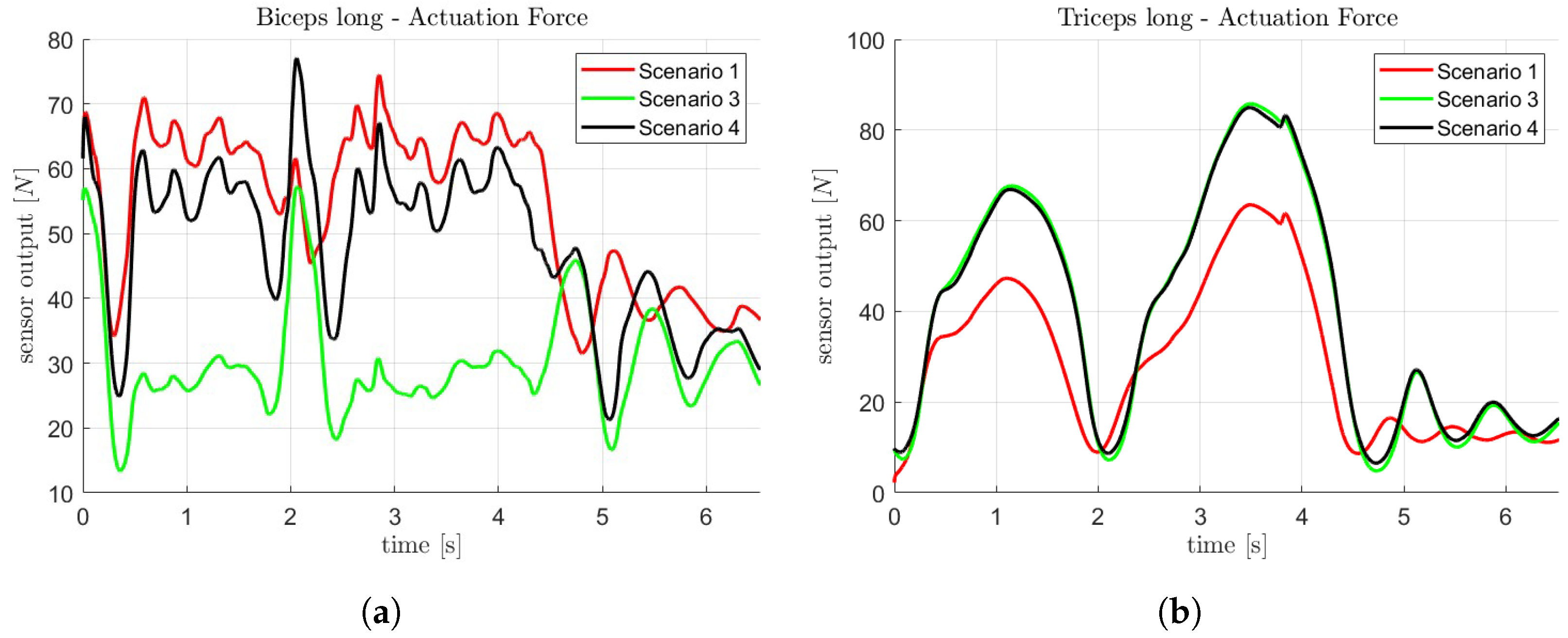
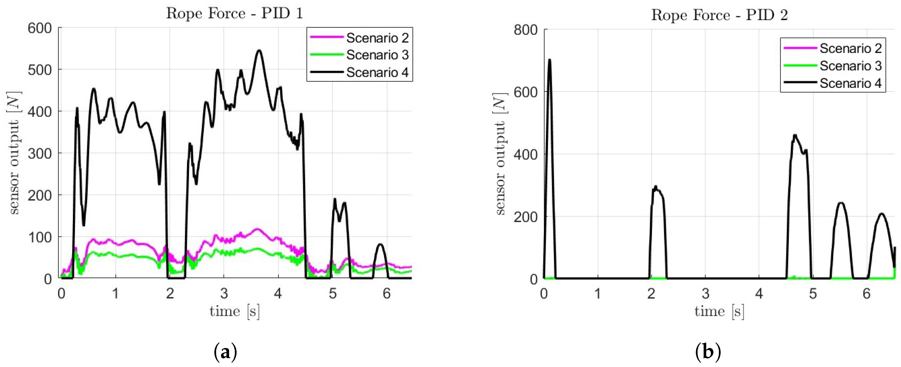
Some of the most relevant features are chosen and shown below to report what leads to the behavior of Figure 9. In particular, actuation forces of muscles acting as agonistic and antagonistic during the exercise, i.e., biceps and triceps, as well as the forces provided by the ropes actuating the exoskeleton for the scenarios exploiting robotic assistance. Muscle actuation forces are recorded only for scenarios that actively involve the patient and are reported in Figure 10a and Figure 10b, whereas rope forces are computed only for tests in which the exoskeleton intervenes.
During the lifting half of the exercise, the biceps exerts the most effort; the opposite applies for the release half, when the triceps is more involved. Considering the lifting, the greatest biceps actuation force is needed in the first scenario, being that it is completely active from the patient’s perspective. After that, scenario 4 requires a great effort due to the heavier gym equipment, but having the exoskeleton supporting the upper limb. In scenario 3, the lowest actuation force is obtained, presenting a patient with reduced activations and assistance from the exoskeleton. It can be seen that biceps and triceps show an opposite trend, meaning that when the biceps force is maximum, the triceps one is minimum and vice versa. The same behavior is also noticeable from the rope actuation forces shown in Figure 11a,b.
Among the assisted scenarios, the fourth one requires a greater actuation force since the weight is 10 kg instead of 1 kg. Scenario 2 requires the next most actuation force as the exercise is completely accomplished by the exoskeleton, and, finally, the lowest force is needed for the scenario where robot and patient cooperate to lift a weight of 1 kg.
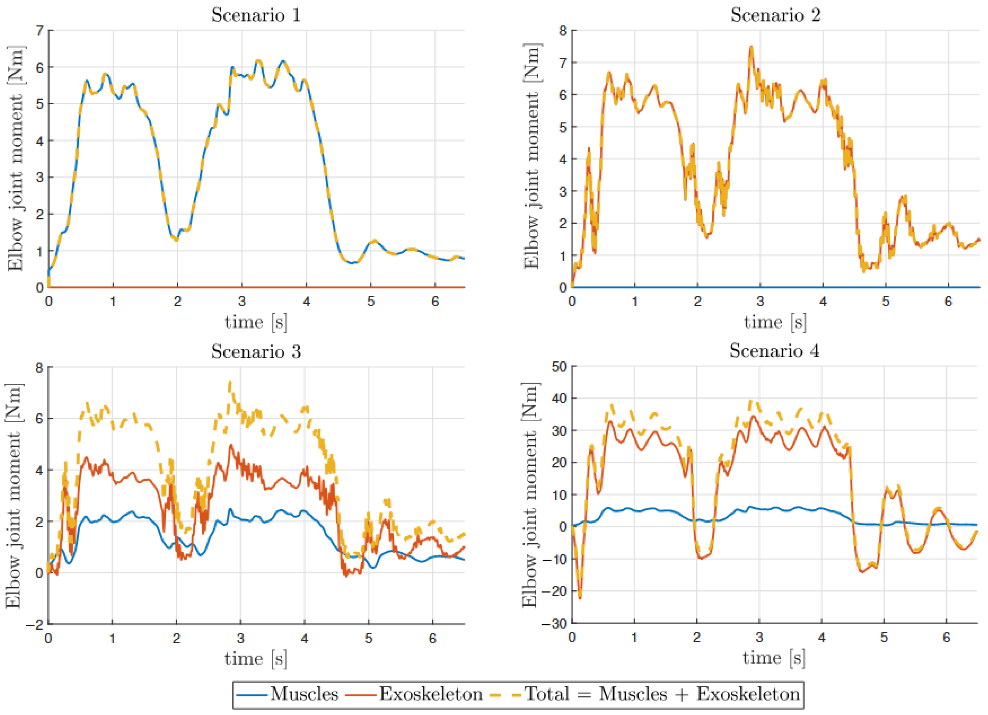
Figure 12 illustrates the equivalent lumped muscle and exoskeleton joint moments applied at the elbow joint to generate arm movement across the analyzed scenarios.
In scenario 1, the muscles alone generate the maximum equivalent joint moment, resulting in an under-target trajectory (Figure 9). This demonstrates the limitation of purely muscle-driven movement when muscle capacity is insufficient. In scenarios 2 and 3, both generate equal total moments, but the exoskeleton’s introduction enables higher joint torque delivery compared to Scenario 1, allowing the controller to successfully follow the reference trajectory.
The controller demonstrates an adaptive torque modulation capability that reflects its ability to respond to varying biomechanical conditions. In Scenario 3, the system strategically reduces the equivalent torque output relative to Scenario 2, creating space for the patient’s residual muscle activity to contribute to the movement. This adaptive behavior underlines that the controller can accommodate existing muscle function rather than simply overriding it. Conversely, in Scenario 4, the controller responds to increased task demands by dramatically scaling up the exoskeleton’s equivalent joint moment delivery to compensate for the tenfold increase in weight (from 1 kg to 10 kg), even when the patient retains full muscle activation capacity.
This analysis reveals the controller’s ability to dynamically adjust assistance levels based on both task demands and patient capabilities, optimizing the human–robot collaboration for effective rehabilitation outcomes.
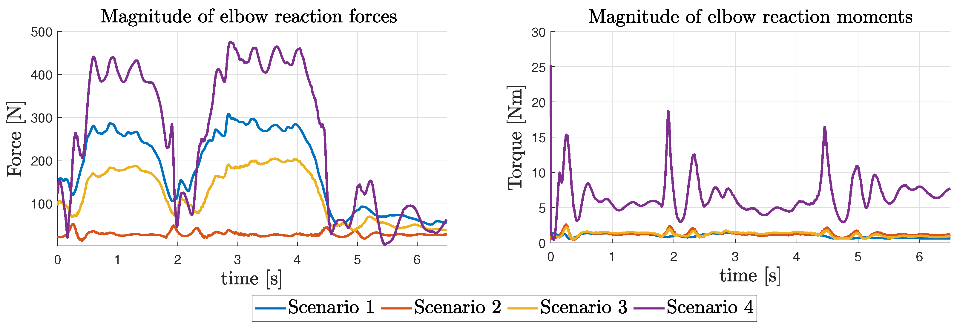
Another interesting analysis is shown in Figure 13 where the reaction forces and moments provided by the revolute joint through the constraint generalized forces are illustrated. Here, it can be observed how the effect of the assistance provided by the exoskeleton drastically reduces the articulation stresses (scenario 2) generated by the muscles due to their anatomical dislocation along the arm (scenario 1 and 3) generating a compressive force additional to the joint moment that provides the movement, while the reaction moments maintain similar levels. For the final scenario, both reaction forces and torques instead increase to counteract the additional weight to be lifted. This analysis provides an evaluation on the effect of exoskeleton on the movement of the wearer.
Finally, Figure 13 presents the reaction forces and moments generated by the revolute joint through constraint-generalized forces, providing quantitative evidence of the biomechanical impact of exoskeleton assistance on joint loading patterns. The results demonstrate that exoskeleton support significantly reduces articulation stresses when comparing Scenario 2 (passive exoskeleton-driven movement) against muscle-driven scenarios. This stress reduction addresses a fundamental biomechanical limitation inherent to human anatomy, where muscles generate compressive forces at the joint due to their anatomical positioning along the arm, in addition to producing the rotational moment required for movement. In Scenarios 1 and 3, where muscles actively contribute to movement, the joint experiences elevated compressive forces as a direct consequence of muscle contraction mechanics. These compressive loads represent the additional structural burden that biological actuation imposes on the skeletal system beyond the primary movement-generating torques. The reaction moments remain at comparable levels across these scenarios, indicating consistent rotational demands regardless of the actuation source. Scenario 4 exhibits a contrasting response pattern, where both reaction forces and torques increase substantially to counteract the increased lifting weight. These findings provide quantitative evidence that exoskeleton assistance can reduce joint loading while preserving functional movement capabilities, with important implications for rehabilitation device design and long-term patient joint health.

6. Conclusions

This work has demonstrated the effective application of the DMS platform in creating a comprehensive multiphysics simulation environment for human–robot interaction analysis. By simulating an assisted gym weightlifting exercise with an upper limb exoskeleton, we have showcased the platform’s versatility in modeling complex multiphysical systems comprising biomechanical, mechanical, and control elements.
The multibody model successfully integrated the biomechanical representation of the human upper limb with a cable-driven exoskeleton controlled by PID controllers. Our approach proved suitable for analyzing multiple scenarios, revealing important insights about patient–robot interactions and providing quantitative data on muscle and actuator forces during assisted movement.
The results demonstrate the potential of this simulation framework to:
  • Customize rehabilitation protocols based on patient-specific needs and impairment levels;
  • Optimize exoskeleton design parameters prior to physical prototyping;
  • Predict and analyze human–robot interaction forces under various loading conditions;
  • Support clinical decision-making by providing quantitative biomechanical insights.
Furthermore, the proposed multiphysics simulation approach paves the way to the development, in future work, of the Digital Twin of the human–exoskeleton ecosystem, which will make it possible to rapidly test multiple design iterations and control strategies. Our simulations confirmed that the exoskeleton could effectively modulate its assistance based on patient capability, providing minimal support for capable users while increasing assistance for those with reduced muscular activation.
The current study lacks proprioceptive feedback in the control strategy. Future work should address this limitation and extend the application in several directions:
  • Implementation of indirect estimation techniques for muscle activities to enable real-time adaptation of robotic assistance;
  • Development of bio-cooperative control strategies that dynamically adjust to patient intention and effort;
  • Integration of ontogenetic sensory feedback mechanisms to enhance patient embodiment and engagement;
  • Validation of the simulation results against experimental data from human subjects;
  • Extension of the model to include more complex upper limb movements and additional degrees of freedom;
  • Realization of simulations suitable for patients with different age and physiognomies, making the future prototype less cumbersome and easily acceptable by the subjects;
  • Optimization of coupling strength parameters between exoskeleton and upper limb to maximize the efficiency of the approach.
In conclusion, the DMS platform represents a powerful tool for advancing rehabilitation robotics by enabling detailed analysis of human–robot interactions in a simulation environment. This approach facilitates patient-centered design, potentially enhancing future device embodiment and acceptance while reducing development costs and accelerating innovation in assistive technologies.

Author Contributions

R.A. developed the platform and the methodology, F.A. performed the literature review, contributed to the development of the methodology and to the drafting of the manuscript, M.P. took care of the implementation and description of the control strategy, D.M. contributed to the development of the methodology and was responsible for the supervision of the work. All authors contributed to the analysis and interpretation of the results. All authors have read and agreed to the published version of the manuscript.

Funding

This research work has been carried out in the context of the National Recovery and Resilience Plan, Investment PE8–Project Age-It: “Ageing Well in an Ageing Society” co-funded by the Next Generation EU [DM 1557 11 October 2022] and in the context of the Decree of the Italian Ministry of University n° 118/2023. The views and opinions expressed are only those of the authors and do not necessarily reflect those of the European Union or the European Commission. Neither the European Union nor the European Commission can be held responsible for them.

Data Availability Statement

The original contributions presented in this study are included in the article. Further inquiries about the results can be directed to the corresponding author.

Conflicts of Interest

The authors declare no conflicts of interest.

Abbreviations

The following abbreviations are used in this manuscript:
ADLActivity of Daily Living
PMAPneumatic Muscle Actuators
TCAMTwisted and Coiled Artificial Muscles
SMAShape-Memory Alloys
DoFDegree of Freedom
DMSDynamics of Multi-physical Systems
MBMultiBody
LPLumped Parameter
ODEOrdinary Differential Equation
EOMEquations Of Motion
DAEDifferential Algebraic Equation

References

  1. Lee, S.H.; Park, G.; Cho, D.Y.; Kim, H.Y.; Lee, J.Y.; Kim, S.; Park, S.B.; Shin, J.H. Comparisons between end-effector and exoskeleton rehabilitation robots regarding upper extremity function among chronic stroke patients with moderate-to-severe upper limb impairment. Sci. Rep. 2020, 10, 1806. [Google Scholar] [CrossRef] [PubMed]
  2. Jamwal, P.K.; Niyetkaliyev, A.; Hussain, S.; Sharma, A.; Van Vliet, P. Utilizing the intelligence edge framework for robotic upper limb rehabilitation in home. MethodsX 2023, 11, 102312. [Google Scholar] [CrossRef] [PubMed]
  3. Tseng, K.C.; Wang, L.; Hsieh, C.; Wong, A.M. Portable robots for upper-limb rehabilitation after stroke: A systematic review and meta-analysis. Ann. Med. 2024, 56, 2337735. [Google Scholar] [CrossRef] [PubMed]
  4. Huang, M.Z.; Yoon, Y.S.; Yang, J.; Yang, C.Y.; Zhang, L.Q. In-bed sensorimotor rehabilitation in early and late subacute stroke using a wearable elbow robot: A pilot study. Front. Hum. Neurosci. 2021, 15, 669059. [Google Scholar] [CrossRef]
  5. Bressi, F.; Campagnola, B.; Cricenti, L.; Santacaterina, F.; Miccinilli, S.; Di Pino, G.; Fiori, F.; D’Alonzo, M.; Di Lazzaro, V.; Ricci, L.; et al. Upper limb home-based robotic rehabilitation in chronic stroke patients: A pilot study. Front. Neurorobotics 2023, 17, 1130770. [Google Scholar] [CrossRef]
  6. Lo, H.S.; Xie, S.Q. Exoskeleton robots for upper-limb rehabilitation: State of the art and future prospects. Med. Eng. Phys. 2012, 34, 261–268. [Google Scholar] [CrossRef]
  7. Pei, S.; Wang, J.; Tian, C.; Li, X.; Guo, B.; Guo, J.; Yao, Y. Assist-as-Needed Controller of a Rehabilitation Exoskeleton for Upper-Limb Natural Movements. Appl. Sci. 2025, 15, 2076–3417. [Google Scholar] [CrossRef]
  8. Mehrholz, J.; Pohl, M.; Platz, T.; Kugler, J.; Elsner, B. Electromechanical and robot-assisted arm training for improving activities of daily living, arm function, and arm muscle strength after stroke. Cochrane Database Syst. Rev. 2015, 2015, CD006876. [Google Scholar] [CrossRef]
  9. Zimmermann, Y.; Sommerhalder, M.; Wolf, P.; Riener, R.; Hutter, M. ANYexo 2.0: A fully actuated upper-limb exoskeleton for manipulation and joint-oriented training in all stages of rehabilitation. IEEE Trans. Robot. 2023, 39, 2131–2150. [Google Scholar] [CrossRef]
  10. Sale, P.; Franceschini, M.; Mazzoleni, S.; Palma, E.; Agosti, M.; Posteraro, F. Effects of upper limb robot-assisted therapy on motor recovery in subacute stroke patients. J. Neuroeng. Rehabil. 2014, 11, 1–8. [Google Scholar] [CrossRef]
  11. Simonetti, D.; Zollo, L.; Papaleo, E.; Carpino, G.; Guglielmelli, E. Multimodal adaptive interfaces for 3D robot-mediated upper limb neuro-rehabilitation: An overview of bio-cooperative systems. Robot. Auton. Syst. 2016, 85, 62–72. [Google Scholar] [CrossRef]
  12. Proietti, T.; Crocher, V.; Roby-Brami, A.; Jarrasse, N. Upper-limb robotic exoskeletons for neurorehabilitation: A review on control strategies. IEEE Rev. Biomed. Eng. 2016, 9, 4–14. [Google Scholar] [CrossRef] [PubMed]
  13. Fareh, R.; Elsabe, A.; Baziyad, M.; Kawser, T.; Brahmi, B.; Rahman, M.H. Will your next therapist be a robot?—A review of the advancements in robotic upper extremity rehabilitation. Sensors 2023, 23, 5054. [Google Scholar] [CrossRef] [PubMed]
  14. Garofalo, S.; Morano, C.; Perrelli, M.; Pagnotta, L.; Carbone, G.; Mundo, D.; Bruno, L. A critical review of transitioning from conventional actuators to artificial muscles in upper-limb rehabilitation devices. J. Intell. Mater. Syst. Struct. 2024, 35, 1263–1290. [Google Scholar] [CrossRef]
  15. Gull, M.A.; Bai, S.; Bak, T. A review on design of upper limb exoskeletons. Robotics 2020, 9, 16. [Google Scholar] [CrossRef]
  16. Tiboni, M.; Borboni, A.; Vérité, F.; Bregoli, C.; Amici, C. Sensors and actuation technologies in exoskeletons: A review. Sensors 2022, 22, 884. [Google Scholar] [CrossRef]
  17. Adduci, R.; Mundo, D. A novel indirect muscle force sensing approach tailored for biomechanical multibody systems with equality and inequality constraints. Mech. Mach. Theory 2025, 214, 106115. [Google Scholar] [CrossRef]
  18. Haug, E.J. Computer Aided Kinematics and Dynamics of Mechanical Systems; Allyn and Bacon: Boston, MA, USA, 1989; Volume 1. [Google Scholar]
  19. Vanpaemel, S.; Vermaut, M.; Desmet, W.; Naets, F. Input optimization for flexible multibody systems using the adjoint variable method and the flexible natural coordinates formulation. Multibody Syst. Dyn. 2023, 57, 259–277. [Google Scholar] [CrossRef]
  20. Adduci, R.; Vermaut, M.; Naets, F.; Croes, J.; Desmet, W. A discrete-time extended Kalman filter approach tailored for multibody models: State-input estimation. Sensors 2021, 21, 4495. [Google Scholar] [CrossRef]
  21. Gear, C.W.; Leimkuhler, B.; Gupta, G.K. Automatic integration of Euler-Lagrange equations with constraints. J. Comput. Appl. Math. 1985, 12, 77–90. [Google Scholar] [CrossRef]
  22. Wang, D.; Ruuth, S.J. Variable step-size implicit-explicit linear multistep methods for time-dependent partial differential equations. J. Comput. Math. 2008, 26, 838–855. [Google Scholar]
  23. Martín-Vaquero, J.; Vigo-Aguiar, J. Adapted BDF algorithms: Higher-order methods and their stability. J. Sci. Comput. 2007, 32, 287–313. [Google Scholar] [CrossRef]
  24. Risaliti, E.; Tamarozzi, T.; Vermaut, M.; Cornelis, B.; Desmet, W. Multibody model based estimation of multiple loads and strain field on a vehicle suspension system. Mech. Syst. Signal Process. 2019, 123, 1–25. [Google Scholar] [CrossRef]
  25. De Jalon, J.G.; Bayo, E. Kinematic and Dynamic Simulation of Multibody Systems: The Real-Time Challenge; Springer Science & Business Media: Berlin/Heidelberg, Germany, 2012. [Google Scholar]
  26. Hill, A.V. The mechanics of active muscle. Proc. R. Soc. Lond. Ser. B-Biol. Sci. 1953, 141, 104–117. [Google Scholar] [CrossRef]
  27. Thelen, D.G. Adjustment of muscle mechanics model parameters to simulate dynamic contractions in older adults. J. Biomech. Eng. 2003, 125, 70–77. [Google Scholar] [CrossRef] [PubMed]
  28. Mashud, G.; Hasan, S.; Alam, N. Advances in Control Techniques for Rehabilitation Exoskeleton Robots: A Systematic Review. Actuators 2025, 14, 108. [Google Scholar] [CrossRef]
  29. Li, Z. Review of PID control design and tuning methods. J. Phys. Conf. Ser. 2023, 2649, 012009. [Google Scholar] [CrossRef]
  30. Ellis, G. Chapter 6-Four Types of Controllers. In Control System Design Guide, 4th ed.; Ellis, G., Ed.; Butterworth-Heinemann: Boston, MA, USA, 2012; pp. 97–119. [Google Scholar] [CrossRef]
  31. Bardi, E.; Gandolla, M.; Braghin, F.; Resta, F.; Pedrocchi, A.L.; Ambrosini, E. Upper limb soft robotic wearable devices: A systematic review. J. Neuroeng. Rehabil. 2022, 19, 1–17. [Google Scholar] [CrossRef]
  32. Perrelli, M.; Lago, F.; Garofalo, S.; Bruno, L.; Mundo, D.; Carbone, G. A critical review and systematic design approach for innovative upper-limb rehabilitation devices. Robot. Auton. Syst. 2025, 183, 104835. [Google Scholar] [CrossRef]
  33. Bessler-Etten, J.; Schaake, L.; Buurke, J.H.; Prange-Lasonder, G.B. Investigating change of discomfort during repetitive force exertion though an exoskeleton cuff. Appl. Ergon. 2024, 115, 104055. [Google Scholar] [CrossRef]
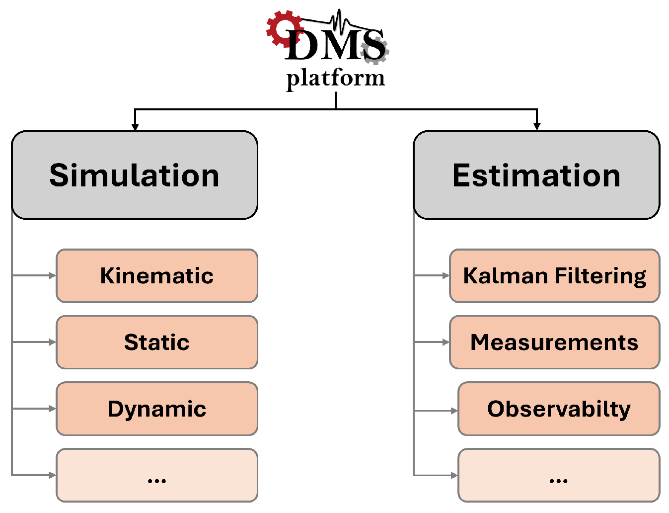
Figure 1. Schematic architecture of the DMS platform.
Machines 13 00895 g001
Figure 2. Schematic architecture of the dynamic simulation branch.
Machines 13 00895 g002
Figure 3. Schematic model architecture of the DMS platform.
Machines 13 00895 g003
Figure 4. Schematic representation of rope forces (black arrows), acting on different anchorage points (blue dots), defining the rope path (orange line) interconnecting several bodies (black shapes).
Machines 13 00895 g004
Figure 5. Schematic muscle muscle representation based on Hill’s theory.
Machines 13 00895 g005
Figure 6. Step response for K p at the critical gain.
Machines 13 00895 g006
Figure 7. Step response after fine-tuning.
Machines 13 00895 g007
Figure 8. Multibody model representation of the multi-physical system (a) comprising: the subject (b), the exoskeleton (c), and the gym equipment (d) subsystems.
Machines 13 00895 g008
Figure 9. Elbow trajectory for the proposed scenarios.
Machines 13 00895 g009
Figure 10. Actuation forces: biceps long (a), triceps long (b).
Machines 13 00895 g010
Figure 11. Rope actuation forces: PID 1 (a), PID 2 (b).
Machines 13 00895 g011
Figure 12. Elbow joint moment for the proposed scenarios joint moment for the proposed scenarios.
Machines 13 00895 g012
Figure 13. Magnitude of the elbow reaction forces and moments for the proposed scenarios.
Machines 13 00895 g013
Disclaimer/Publisher’s Note: The statements, opinions and data contained in all publications are solely those of the individual author(s) and contributor(s) and not of MDPI and/or the editor(s). MDPI and/or the editor(s) disclaim responsibility for any injury to people or property resulting from any ideas, methods, instructions or products referred to in the content.