Abstract
This study investigates the 3RPUR (3-Revolute–Prismatic–Universal–Revolute) variable parallel mechanism, employing screw theory and linear geometry to analyze the geometric relationships and constraint characteristics of the RPUR (Revolute–Prismatic–Universal–Revolute) limb kinematic pairs. The findings reveal that the constraint moment in the always remains perpendicular to the two axes of the U pair, forming an equivalent plane. Through the locking/unlocking mechanism of universal joints (U pair), the mechanism achieves dynamic degree-of-freedom reconstruction, enabling seamless switching between three translational (3T) and three translational-one-rotation (3T1R) motion modes. The continuity between motion and degrees of freedom during the variable cell process is demonstrated. This research reveals a strict 1:1 linear coupling between the rotational angle of the moving platform around the Z-axis and the U pair’s rotation angle under 3T1R mode. Simulation experiments validate the feasibility and coupling characteristics of both motion modes, providing theoretical and technical support for this mechanism’s adaptation to complex working conditions in mobile robotics applications, particularly where reconfigurable parallel mechanisms are required for multi-task flexibility.
1. Introduction
Parallel mechanisms, as the core components of modern mechanical equipment, face inherent limitations in their fixed topological structures and rigid degree-of-freedom (DOF) configurations, which constitute critical bottlenecks for functional expansion. In traditional parallel mechanisms (e.g., Stewart platforms), once the limb topology and joint types are determined, the number of DOFs and motion patterns become permanently locked, making them difficult to adapt to multi-task requirements under varying working conditions [1]. Research by Dai et al., A fellow of the Royal Academy of Engineering, demonstrates that many typical applications such as precision assembly require mechanisms to simultaneously possess both high-precision translational positioning and attitude adjustment capabilities—a demand that conventional fixed-DOF mechanisms often fail to meet with their single-function limitations [2]. These constraints have driven breakthroughs in mechanism science toward dynamic topological reconfiguration [3].
Metamorphic mechanisms and reconfigurable mechanisms offer novel pathways by actively altering the topological structure of kinematic chains or the constraint characteristics of joints [4]. As highlighted by Bo Han from Chi Zhang’s research team at the University of Michigan, the core of metamorphic mechanisms lies in “configuration evolution,” achieved through hinge mode switching (e.g., locking/unlocking kinematic pairs) to modify constraints [5]. This principle of configuration evolution finds a concrete and innovative embodiment in the concept of ‘Metamorphic Oriblocks’, which are constructed through the cutting and linking of geometric primitives like cylinders and cones, offering a novel approach to designing reconfigurable joints and limbs [6]. Research by Lin Wang from the Hiller group at the Technical University of Munich [7] demonstrates that reconfigurable mechanisms can induce rank reduction in the motion screw system by adjusting the geometric parameters of kinematic chains [8], enabling smooth transitions between motion modes. Both approaches address the challenge of dynamic degree-of-freedom (DOF) regulation [9]—specifically, by actively modifying chain topology, joint constraints, or geometric parameters to achieve flexible switching of mechanism configurations/motion modes, thereby providing a theoretical foundation for dynamic adaptability in mechanisms [10].
Jingjun Yu, Zhen Huang, and others proposed a novel method for the type synthesis of three-degree-of-freedom translational parallel mechanisms using screw theory. Based on research by Xianwen Kong from ETH Zurich’s Katzschmann group [11], substituting certain simple joints in the PPRRR kinematic chain with composite joints such as 4R, 4U, 4S, or 3-2S led to the derivation of new translational parallel mechanisms like the 3-RPUR [12]. Simulation studies by Yan’an Yao’s team at Beijing Jiaotong University [13] demonstrated that this mechanism can achieve dynamic switching between 3 and 5 degrees of freedom by controlling the locking/unlocking states of universal joints (U-joints) [14].
The 3-RPUR parallel mechanism enables changes in the degrees of freedom (DOF) of the moving platform by controlling the locking/unlocking of the revolute joints connected to the U-joints in its kinematic chains, making it an ideal platform for studying metamorphic mechanisms [15]. Research by Park at KAIST using digital twin technology confirmed [16] that changes in the rank of the constraint screw system of the chains during U-joint state switching directly alter the DOF of the moving platform [17]. This study analyzes the DOF variations in the 3-RPUR mechanism under U-joint locking/unlocking from the perspective of constraint changes, employing line geometry and chain geometric relationships, while also exploring motion continuity. The dynamic constraint analysis framework established by Carricato at CNRS [18] provides theoretical support for this investigation [19].
The line geometry method in screw theory enables direct derivation of limb constraints from geometric relationships between joint axes, making it widely applicable for mechanism mobility analysis [20]. However, continuous changes in these geometric relationships during mechanism motion pose significant challenges for real-time constraint determination [21].
2. Analysis of RPUR Limb
2.1. Geometric Criterion for Reciprocal Screws
In “On the Degrees of Freedom of Mechanisms”, the geometric method for determining reciprocal screws is based on the following two properties:
(1) A line vector reciprocal to a screw system must be perpendicular to all couple vectors in that system and must either intersect or be parallel to all line vectors.
(2) A couple vector reciprocal to a screw system must be perpendicular to all line vectors in that system.
From these properties, two corollaries can be derived [22].
Corollary (1): The constraint force of a limb must intersect or be parallel to all revolute joint axes and must be perpendicular to the direction of all prismatic joint guides.
Corollary (2): The constraint couple of a limb must be perpendicular to all revolute joint axes in the limb.
2.2. Analysis of the RPUR Limb
A linear vector represents both the kinematic pair it corresponds to, and the axis associated with that pair. Regarding universal joints (U-frames), their fundamental mechanism involves combining two single-degree-of-freedom revolute pairs (abbreviated as R pairs) through series connection [23]. The rotational axes of these two R pairs are spatially orthogonal (perpendicular to each other) and share a common intersection point (the universal joint’s center). The combined motion constraints create two independent degrees of freedom enabling rotational movement in orthogonal directions. This configuration makes the overall motion behavior of the universal joint completely equivalent to that of a composite R pair with perpendicular axes [24].
As shown in Figure 1a, the RPUR support chain consists of a rotational joint connected to the lower (fixed) platform, a rotational joint linked to the upper (moving) platform, and two rotational joints and connected to the telescopic connecting rod, which is represented by a moving joint . plotting the line vector representing the kinematic axes of the joints, the simplified diagram of the RPUR support chain can be obtained as shown in Figure 1b [25].
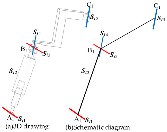
Figure 1.
The RPUR limb.
In the RPUR branch, the motion pair axis satisfies the following geometric relationship (1).
Line clusters are classified into singular line clusters (e.g., “plane line clusters” where all lines lie in the same plane and pass through a common point) and non-singular line clusters (where lines are not coplanar but coaxial). Based on the geometric constraint relationship (1) of the RPUR branch chain, the spatial orientations of the motion pair shafts are not coplanar. Therefore, the motion pair shafts of this branch chain belong to a non-singular line cluster. The motion pair shafts of the RPUR branch chain form a non-singular line cluster due to their coaxial intersection and non-coplanar distribution. In conjunction with the conclusion from spin theory that “non-singular line clusters correspond to five-dimensional spin systems”, the motion spiral system of this branch chain constitutes a spin five-system (containing 5 degrees of freedom and 1 constraint). The following section will analyze the constraint characteristics of the RPUR limb based on these geometric properties.
2.3. RPUR Branched Constraint Analysis
Since the branch chain has only one constraint, let be a couple of forces. Inference (2) is satisfied when is perpendicular to or is contained in the plane formed by and .
Proof: Since , and and lie on the same connecting rod, no matter how they change, and remain parallel. Similarly, and lie in the same plane of the connecting rod, maintaining parallelism through any rotation or movement. Therefore, the plane formed by and is always parallel to the plane formed by and . Combining this with the given assumption, we conclude that is perpendicular to the plane formed by and .
can be obtained that the plane composed of and is parallel to the plane composed of and , so is perpendicular to the plane composed of and , so it is proved.
In conclusion, the constraint moment is perpendicular to the plane formed by and (or and ). The constraint moment of the support link can be replaced by the normal of the plane formed by these components to analyze the degrees of freedom of the mechanism. As the support link moves, the position and orientation of the plane will change accordingly.
Note1: Since the couple is a special linear vector (free vector), the position can be moved in parallel, so the restriction on does not affect the analysis results.
Note2:
2.4. Analysis of RPUR Metamorphic Kinematic Chain
From Section 2.2, it can be concluded that the constraint couple of the RPUR limb lies in the plane perpendicular to the axes ( and ) of the upper and lower platforms. Evidently, the direction of this couple is either parallel to or within the planes of the two platforms. In the RPUR parallel mechanism, a lockable universal joint (U-joint) is introduced to achieve dynamic adjustment of degrees of freedom (DOF). By integrating an electromagnetic braking module into the U-joint, one rotational DOF (revolute joint) can be selectively locked or unlocked, enabling the limb topology to switch between RPUR (R-P-U-R) and UPUR (U-P-U-R). By controlling only one limb—specifically, one revolute joint within the U-joint of that limb—the DOF of the moving platform can be altered, thereby expanding the mechanism’s functional capabilities.
As shown in Figure 2a, in the metamorphic limb, the revolute joint is connected to the lower (fixed) platform, the revolute joint is connected to the upper (moving) platform, and the revolute joints and are connected to the telescopic link, which is represented by the prismatic joint . Based on the RPUR limb, the revolute joint (R-joint) connected to the lower (fixed) platform is replaced with a universal joint (U-joint) (by releasing the other rotational DOF of the U-joint), and an additional revolute joint is introduced.
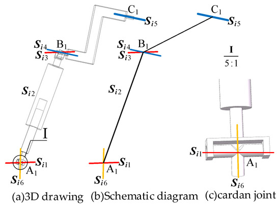
Figure 2.
Branching variant cells.
Using line vectors to represent the joint axes, the simplified schematic of the metamorphic limb can be obtained, as shown in Figure 2b. The joint axes in the metamorphic limb satisfy the following geometric relationship (2).
3. DOF Analysis of the 3RPUR Metamorphic Parallel Mechanism
Since the universal joint (U-joint) only functions during the mode transition from 3T to 3T1R, while behaving as a standard revolute joint (R-joint) in other cases, the DOF analysis of the metamorphic mechanism can be simplified to analyzing the 3T mode (3RPUR three-translational-DOF parallel mechanism) and the 3T1R mode (3UPUR three-translational and one-rotational-DOF parallel mechanism). By integrating electromagnetic braking modules into the U-joints, one rotational DOF can be selectively locked. Under normal conditions, all three limbs remain in the RPUR configuration. When rotation is required, the other rotational pair within the U-joint is released, effectively unlocking the U-joint constraint.
3.1. Metamorphic Mechanism in 3T Mode
As shown in Figure 3, when the revolute joint of the U-joint at A3 is locked, only the axis of remains released, which is functionally identical to the revolute joint A1A2A3 connected to the lower platform. Each limb retains five degrees of freedom (DOF) and one constraint couple. A coordinate system is established with the centroid (O) of the equilateral triangular lower platform as the origin. The X-axis is aligned with the direction from O to A1, the Y-axis is horizontally perpendicular to the X-axis, and the Z-axis is vertically perpendicular to the XY-plane. In the 3T mode, the metamorphic mechanism has O as its constrained rotation center (all coordinate systems in the figures follow the same convention as in Figure 4 and are not explicitly shown).
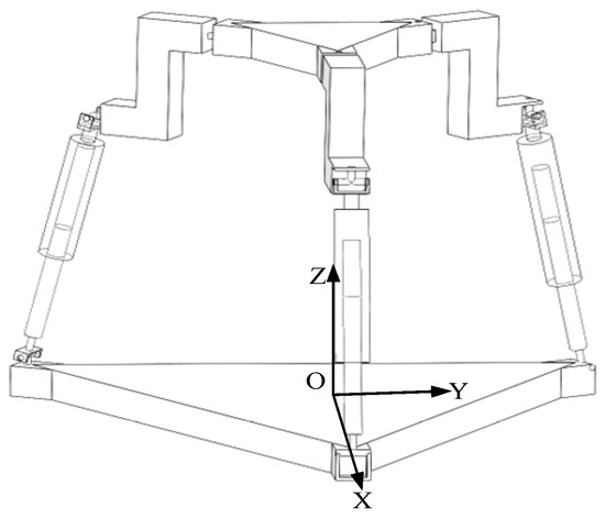
Figure 3.
The 3RPUR metamorphic parallel mechanism.
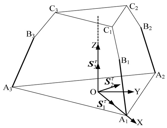
Figure 4.
Equivalent diagram of the 3T mode.
The constraint couples from all three limbs are analyzed using an equivalent simplified diagram to determine the mechanism’s DOF.
When the constraint couples of all three limbs are translated to the space with O as the origin, the plane formed by the constraint couple from limb A1B1C1 and the constraint couple from limb A2B2C2 is parallel to the plane . Meanwhile, the constraint couple from limb A3B3C3 is perpendicular to and , and thus perpendicular to the plane , aligning along the Z-axis direction. The constraint couples intersect at point O. By arbitrarily combining any two of these three constraint couples, it is evident that all rotational DOFs in the coordinate system are constrained. Consequently, the constraint couples from the three limbs collectively form a three-system constraint space, resulting in three remaining degrees of freedom.
3.2. Continuity Criterion for Translational Degrees of Freedom
As shown in Figure 5, when the upper platform C1C2C3 undergoes displacement in any direction about point O, the axes of and remain unchanged. Consequently, the direction of the constraint couple remains perpendicular to the plane formed by these two axes. In Figure 1, the geometric relationship (1) ensures that and maintain a constant parallel alignment (with a fixed orientation) as long as the structural integrity is preserved. After arbitrary displacement, the direction of the constraint couple remains perpendicular to the plane formed by and . Translating the displaced constraint couples to point O, the plane formed by these couples in the coordinate system remains parallel to the plane, while the third constraint couple still aligns with the Z-axis. The spatial intersection of constraint couples transforms into a concurrent spatial configuration, forming a three-system constraint space that ensures 3T (three translational) degrees of freedom.
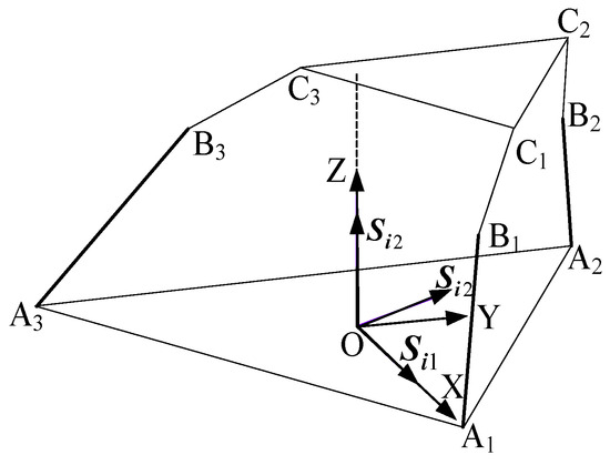
Figure 5.
The 3T mode in motion.
3.3. T1R Mode of the Metamorphic Mechanism
As shown in Figure 6, when the revolute joint of the U-joint at A3 is released, the revolute joint effectively functions as a U-joint. For limb , this limb behaves as a six-system screw, imposing no constraints. Limbs and each retain five degrees of freedom and one constraint couple. A coordinate system is established with the centroid (O) of the equilateral triangular lower platform as the origin. The X-axis is aligned with the direction from O to A1, the Y-axis is horizontally perpendicular to the X-axis, and the Z-axis is vertically perpendicular to the XY-plane, pointing toward the centroid of the upper platform. In the 3T1R mode, the metamorphic mechanism has O as its constrained rotation center (all coordinate systems in the figures follow the same convention as in Figure 3 and are not explicitly shown).
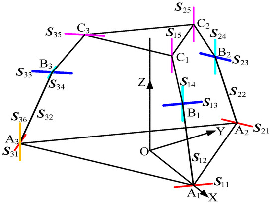
Figure 6.
Diagram of the 3T1R mode mechanism.
There are two constraint couples, , from the two limbs. We use an equivalent schematic for analysis.
As shown in Figure 6 and Figure 7, at the initial moment, the plane formed by is parallel to the plane. It follows that the constraint couple lies within the plane but does not coincide with it. Translating to point O, the constraint couples from all three limbs are projected into the space with O as the origin. Here, the constraint couple from limb and the constraint couple from limb form a plane parallel to the plane, while limb imposes no constraint force or couple. The constraint couples and intersect at point O, clearly restricting all rotational degrees of freedom in the plane of the coordinate system. Thus, the constraint couples from the three limbs converge in space to form a two-system constraint, resulting in 3T1R (four degrees of freedom) for the mechanism.
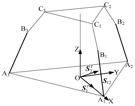
Figure 7.
Equivalent diagram of the 3T1R mode.
3.3.1. Continuity Criterion for Rotational Degrees of Freedom
As shown in Figure 8, when the upper platform rotates about the center O along the Z-axis in any direction, the structural properties ensure that the axis remains unchanged in orientation, preserving the constraint. After rotation, and continues to be parallel to the plane without coinciding. Translating to point O, the plane formed by the two constraint couples remains parallel to the plane, thereby restricting rotation in the plane direction while releasing rotational freedom along the Z-axis with a constant orientation. he coplanar intersection of constraint couples in and transforms into a concurrent spatial configuration, forming a two-system constraint that ensures 3T1R (four degrees of freedom). The rotational degree of freedom remains continuous about the Z-axis.
Figure 8.
The 3T1R mode after rotating.
Due to the geometric correlation between the rotating shaft and the motion platform’s rotation, the associated axis direction is the rotatable axis within the U-joint, which remains perpendicular to the fixed platform’s XY plane (ensured by the mechanism’s initial design and symmetry). When the motion platform rotates about the Z-axis, its rotational axis aligns collinearly with the axis (both being the Z-axis). During the motion platform’s rotation, the constraint torque directions of the two constrained branched chains remain parallel to the XY plane (determined by the geometric relationship of the chain axes), and their spatial orientation does not change with the motion platform’s rotation.
According to the geometric relationship (2), the axes , , , combined with the axis configuration in Figure 9 (spatial arrangement of the metamorphic branched chain), are analyzed. The rotation axis of the U-joint and the motion platform’s attitude rotation axis about the Z-axis are spatially collinear (or strictly aligned). This geometrically symmetric layout constitutes a linear coupling condition. The motion platform’s attitude variation about the Z-axis—i.e., its rotation angle—and the U-joint’s rotation angle exhibit no spatial offset or misalignment, providing the geometric foundation for their “rotational synchronization.” That is, the attitude rotation and U-joint rotation share the same axis direction, ensuring motion transmission without additional nonlinear deviation. Moreover, the constraint torque remains perpendicular to the motion platform’s XY plane (aligned with the Z-axis rotation direction). The key effect of this constraint is that the U-joint’s rotation only needs to counteract the “constraint torque along the Z-axis,” while the motion platform’s rotation angle about the Z-axis and the U-joint’s rotation angle remain synchronized under the condition of a “fixed constraint torque direction,” with no additional degree-of-freedom interference. This enforces a linear mapping between their rotational relationships (free from nonlinearity caused by complex spatial force coupling). This precise alignment ensures that the rotational transformation is transmitted without introducing parasitic motions or nonlinear kinematic coupling, which is crucial for maintaining motion accuracy.
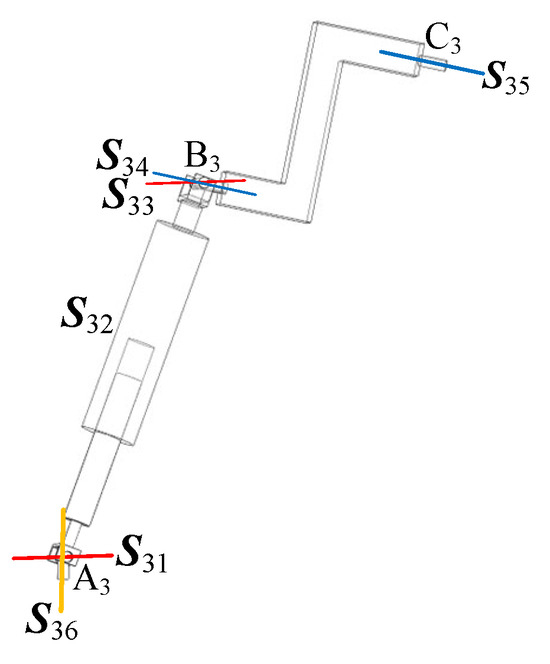
Figure 9.
Diagram of branched chain axis relationship between variant cells.
The essence of this coupling lies in the mechanism’s topological constraints (geometric and mechanical), which enforce that the “motion platform’s attitude rotation” and the “U-joint rotation” share the same axis direction, with motion transmission free from additional nonlinear disturbances. Ultimately, this manifests as a linear mapping between their rotation angles [26]. The following simulation experiment verifies this by testing the angular displacement of the revolute joint in both the motion platform and the U-joint.
As shown in Figure 10, the motion platform undergoes pose planning to first execute a fixed-angle rotation in the attitude domain (about the center point of the moving platform along the Z-axis), followed by a fixed-distance translation in the position domain, and finally a fixed-angle rotation (or attitude reset) in the attitude domain. During the initial rotation phase (0–2 s), the motion platform rotates about the Z-axis to alter its attitude, while the U-joint synchronously rotates to drive this attitude change—both the motion platform’s angular displacement (Figure 10) and the U-joint’s rotation angle (Figure 11) decrease over time, demonstrating the coupled relationship of “attitude change and joint angle synchronous variation” [27].
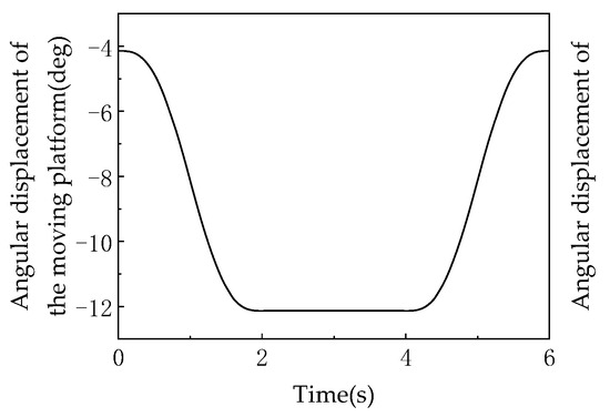
Figure 10.
The center point of the motion platform rotates.
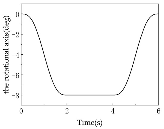
Figure 11.
Rotating shaft rotation (U-lead).
In the translation phase (2–4 s), the motion platform only translates along a certain direction while maintaining a constant attitude (no rotation). At this stage: The motion platform’s angular displacement enters a “plateau” (horizontal curve in Figure 10), indicating no attitude change. The U-joint’s rotation angle also synchronously reaches a “plateau” (horizontal curve in Figure 11), reflecting the kinematic mapping of “constant attitude → constant joint angle” (joint angle stabilizes in sync with the end-effector’s attitude). During the reverse rotation phase (4–6 s), the motion platform rotates about the Z-axis in the opposite direction to reset its attitude, while the U-joint synchronously reverses its rotation—both the motion platform’s angular displacement (Figure 10) and the U-joint’s rotation angle (Figure 11) increase over time, achieving symmetric attitude reset [28].
The rotation axis of the U-joint aligns with the attitude rotation axis of the moving platform (due to the mechanism’s symmetric configuration), and within small-angle motion ranges, the attitude angle of the moving platform and the rotation angle of the U-joint exhibit a linear mapping relationship. Consequently, the angular variation during the rotation phase demonstrates a “smooth and slope-stable” quasi-linear characteristic.
The angular variation patterns of the moving platform and the U-joint result from the kinematic coupling of “motion planning → end-effector attitude → joint angle.” Translation phase: Constant attitude → constant joint angle (synchronized plateau). Rotation phase: Symmetric attitude variation → symmetric linear variation in joint angle (synchronized magnitude and trend of angular change). Such patterns are prevalent in parallel robots (e.g., Stewart platforms) and serial/hybrid mechanisms incorporating universal joints, profoundly reflecting the kinematic essence of “end-effector pose being cooperatively driven by joint motion.”
From the perspective of degree-of-freedom uniqueness, in the 3T1R mode, the moving platform possesses only a single rotational degree of freedom about the Z-axis. According to motion continuity requirements, this rotation must synchronize with the rotation of the axis. If their angles differ, the direction of the constraint torque will deviate from the XY plane, disrupting constraint consistency and contradicting screw theory. The base platform is an equilateral triangle with three branched chains symmetrically distributed at 120° intervals. The rotation angle of the axis () directly corresponds to the rotation angle of the moving platform about the Z-axis (). Since the mechanism has no elastic deformation and all kinematic pairs are ideally rigid, and satisfy = (with a linear proportionality factor of 1). The rotation angle of the axis and the moving platform’s rotation angle are identical and exhibit a linear relationship (proportionality factor of 1). This relationship is fundamentally determined by the mechanism’s topological constraints, the invariance of the constraint torque direction in screw theory, and geometric symmetry. This relationship ensures the continuity and uniqueness of the rotational degree of freedom about the Z-axis in the 3T1R mode, fulfilling the kinematic consistency requirements of the mechanism. After elaborating on the continuity and uniqueness of the rotational degree of freedom of the moving platform in 3T1R mode and the supporting role of screw theory, Table 1 can be used to systematically outline the logical relationships between screw theory and the key mechanism characteristics, thereby clarifying the correspondence between theoretical principles and practical mechanism behaviors.

Table 1.
Correlation Between Screw Theory and 3T1R Mechanism Properties.
3.3.2. Continuity Criterion for Translational Degrees of Freedom
As shown in Figure 12, when the upper platform moves in an arbitrary direction around point O through coordinate system , the direction of the axis remains unchanged after displacement. The direction of the constraint torque remains perpendicular to the plane formed by and its paired axis. From the geometric relationship (1) in Figure 9, as long as the structure remains intact, the parallelism condition of remains invariant (with a fixed directional alignment). After arbitrary displacement, the constraint torque remains perpendicular to the plane formed by and . When the displaced constraint torque is rotated to point O, its plane—expressed in the coordinate system—remains parallel to the plane. The spatial intersection condition transforms into a spatial concurrent point, forming a two-system constraint torque. This results in a 3T1R configuration with three translational degrees of freedom. Regardless of how the upper platform moves, the constraint conditions and their form remain unchanged. This ensures the continuity of translational degrees of freedom while preserving the mechanism’s kinematic consistency.
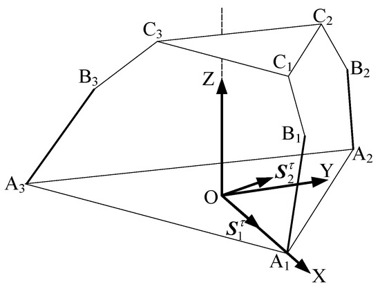
Figure 12.
The 3T1R mode in motion.
As shown in Figure 13, after the rotation and translation of the upper platform, when the upper platform undergoes arbitrary rotation about the Z-axis and free spatial movement, the intersecting plane of kinematic chain remains unchanged due to the invariant mechanism configuration.
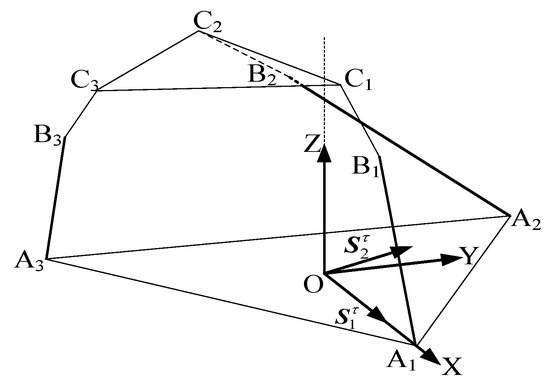
Figure 13.
The 3T1R mode after rotation and movement.
4. Inverse Position Analysis of the 3RPUR Metamorphic Parallel Mechanism
Inverse position analysis includes numerical and algebraic methods. The algebraic method is primarily based on classical elimination theory in algebraic geometry. It involves formulating kinematic equations according to the coordinates of points on the moving platform and its motion state. By transforming the form of the kinematic equations, elimination is performed to establish a linear system containing only one unknown. The solution is obtained when the determinant of the system equals zero, yielding all possible roots—each representing the length of a particular link after the rotation of the moving platform. These roots are then used to solve the lengths of other links. However, the algebraic method involves computing high-order determinants and roots of high-degree polynomials, resulting in significant computational complexity. Numerical methods include analytical and geometric approaches. The analytical method simplifies the kinematic equations of the mechanism and obtains the inverse solution by solving trigonometric functions. However, its computational load is high, affecting real-time performance in practical applications. The geometric method, on the other hand, establishes closed-loop constraint equations for the parallel mechanism. By utilizing simple geometric relationships such as trigonometric functions, the position coordinates of key points on the fixed platform, moving platform, and connecting links are determined, thereby solving for the link lengths. This method is more intuitive and computationally efficient. Therefore, this study adopts the geometric method (closed-loop vector method) in inverse position analysis to solve for the lengths of the driving links.
As shown in Figure 14, the 3T1R mode possesses four degrees of freedom, with three prismatic joints on the kinematic chains selected as actuated joints to establish the relationship between the driving variables and the rotational variables of the moving platform. The fixed platform is configured as an equilateral triangle with its centroid at the origin, where the positive X-axis direction is defined from point O toward point A2, the Y-axis lies horizontally perpendicular to the X-axis, and the Z-axis extends vertically perpendicular to the plane formed by the X and Y axes, directed from point O toward the centroid of the moving platform [29].
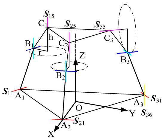
Figure 14.
Initial geometrical conditions of the mechanism.
From the initial position, it can be obtained that
The initial configuration parameters of this mechanism can be precisely defined as follows: the circumradius of the moving platform’s triangular structure is 30 mm, the circumradius of the fixed platform’s triangular structure is 90 mm, and the initial vertical distance between the two platforms is 120.99 mm. Through trigonometric geometric analysis, the key parameters characterizing the triangular features of both platforms are determined, a = 89.9984 mm, b = 70.9991 mm, c = 30.9991 mm, , as well as the heights at reference points on specific edges being = 85.99 mm and = 115.99 mm. These parameters establish the structural reference for subsequent pose transformations and link length calculations. This homogeneous transformation matrix formulation assumes small-angle rotations for linearization within the local workspace, which is valid for the operational range of the mechanism discussed herein.
In kinematic analysis, the pose of the moving platform is described by both linear and angular displacements: the linear displacement components along the fixed coordinate system (X, Y, Z axes) are denoted as , , , respectively, while the angular displacement about the Z-axis (i.e., rotational transformation angle) is denoted as . Based on geometric relationships, we have
Based on rigid-body kinematics principles, the pose transformation of the moving platform requires composite operations of rotational and translational transformations. The rotational transformation about the Z-axis is characterized by the rotation matrix, expressed as
This matrix describes the orientation change in the moving coordinate system relative to the fixed coordinate system. The translational transformation is achieved through a translation matrix, expressed in vector form as T, representing the overall translational displacement of the moving platform.
The initial position vector of the moving coordinate system’s origin in the fixed coordinate system is updated after composite transformation. Assuming the position vector of the moving coordinate system’s origin relative to the fixed coordinate system’s origin in the initial state is (with its magnitude corresponding to the initial vertical distance of 120.99 mm), the transformed position vector of this origin satisfies
In the 3T (Three-Translational) mode, which possesses three degrees of freedom, the prismatic joints on three kinematic chains are selected as the actuated joints to establish the relationship between the driving variables and the rotational variables of the moving platform. The fixed platform is an equilateral triangle with its centroid at the origin. The X-axis is defined in the positive direction from point O toward point A2, the Y-axis is horizontally perpendicular to the X-axis, and the Z-axis is vertically perpendicular to the plane formed by the X and Y axes, pointing from point O toward the centroid of the moving platform.
As shown in Figure 15, compared to the 3T1R (Three-Translational and One-Rotational) mode, this mode lacks one rotational degree of freedom and can be regarded as a special case of the 3T1R mode. When the rotational angle equals 0°, the 3T1R mode reduces to the 3T mode. Therefore, the inverse position analysis of the 3T1R mode can also be applied to analyze the 3T mode [30].
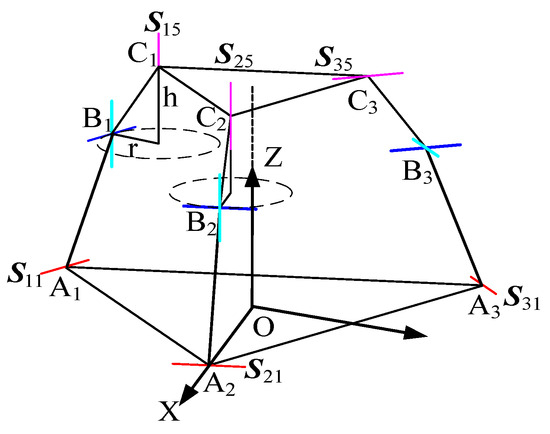
Figure 15.
Equivalent diagram of the 3T mode.
From the geometric relationships, it follows that
where c denotes the cos () function, s denotes the sin () function, and t denotes the tan () function (the same convention applies hereafter). By combining Equations (3)–(9), the y-coordinate of point B on kinematic chain 2 after the 3T1R mode transformation is obtained as
where the x and y coordinates of point D on kinematic chain 2 after the 3T1R mode transformation are, respectively,
The solution for the driving link lengths is based on the closed-loop vector method, which serves as the core technique for inverse position analysis in parallel mechanisms. The principle is as follows: within the closed-loop vector chain formed by the fixed platform, moving platform, and driving links, all vectors satisfy the equilibrium equation, ultimately yielding the link length:
By combining Equations (10)–(13), the lengths of driving links 1 and 2 in the 3T1R mode are obtained.
Similarly, the length of the driving link in the metamorphic kinematic chain can be determined. Following the same approach as in Equations (1)–(10) and utilizing geometric relationships, the y-coordinate of point B on kinematic chain 3 is obtained as
where the x and y coordinates of point D on kinematic chain 3 after the 3T1R mode transformation are, respectively,
By combining Equations (1)–(10) and (15)–(18), the length of driving link 3 in the 3T1R mode is obtained.
In summary, the core methodology involves establishing a mapping relationship between the pose parameters of the parallel mechanism and the driving link lengths through rigid-body kinematic transformations and closed-loop vector equilibrium. This constitutes a fundamental step in the kinematic analysis of parallel robots, where its accuracy directly impacts trajectory planning and dynamic performance.
Workspace analysis facilitates an intuitive understanding of the mechanism’s motion range. The primary influencing factors of the workspace include stroke limits of prismatic joints and angular constraints of kinematic pairs. The workspace boundary is determined by synthesizing these constraints through numerical or geometric methods, providing critical guidance for mechanism design and motion control.
As shown in Figure 16, the three-branch symmetric configuration of the 3-RPUR mechanism results in a workspace exhibiting multiple geometric symmetries. The XY-plane demonstrates central symmetry about the coordinate origin (the reference center of the moving platform), with symmetric motion ranges along the X and Y axes, as evidenced by the near-circular projection in Figure 16b, indicating uniform horizontal coverage. The XZ and YZ planes exhibit approximate symmetry about the X = 0 and Y = 0 planes, respectively, as seen in the left-right and front-back symmetric cross-sectional curves in Figure 16c,d, reflecting consistent motion characteristics along the X and Y directions. The Z-coordinate decreases monotonically with increasing radial distance from the origin, illustrated by the color gradient from red at the center to blue at the edges in Figure 16b, and by the reduction in Z-values with increasing absolute X/Y values in Figure 16c,d, indicating progressively constrained vertical mobility with horizontal displacement from the center. The achievable range along the X and Y directions is approximately ±40 units, defining the horizontal motion boundaries, while the minimum Z-values at the periphery correspond to the stroke limits of prismatic joints or angular limits of revolute joints. The XZ and YZ cross-sections in Figure 16c,d display symmetric parabolic or arc-shaped curves, confirming the monotonic decrease in vertical height with horizontal displacement and further validating the structural symmetric constraints on the workspace. In summary, the 3-RPUR parallel mechanism features a centrosymmetric, bell-shaped convex three-dimensional workspace, where horizontal coverage is jointly constrained by prismatic joint strokes and revolute joint rotation ranges, vertical height decreases with increasing radial distance, and peripheral regions exhibit reduced mobility due to joint limit constraints compared to the central zone.
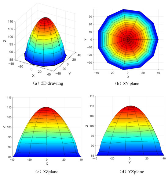
Figure 16.
The 3-RPUR organizational workspace diagram.
5. Simulation Analysis of the 3RPUR Metamorphic Parallel Mechanism
Robot path planning involves three tasks: defining a geometric curve for the end-effector between two points, specifying motion between two orientations, and establishing a time function for coordinates changes between two given values. To ensure mechanism stability, sinusoidal functions are selected for the displacement and velocity profiles of the moving platform. The time-dependent curves are defined as and representing the motion duration, while denotes the magnitude of displacement.
The subsequent stage of this research will employ Fourier decomposition for frequency-domain insight and implicit numerical methods to handle more complex, non-sinusoidal trajectory planning and dynamic loading conditions, building upon the harmonic analysis established here.
By integrating Equations (15) and (16), an expanded analysis of the 3RPUR metamorphic parallel mechanism is conducted. The segmented displacement actions in three-dimensional space enable the moving platform to complete mode transitions within three time intervals: operating in 3T1R mode from 0 to 2 s, switching to 3T mode between 2 and 4 s, and finally reverting to 3T1R mode while simultaneously returning to the initial positional state during the 4 to 6-s interval. This phased motion sequence demonstrates the mechanism’s dynamic reconfigurability through controlled kinematic chain adjustments and coordinated actuator displacements.
As shown in Figure 17, this graph quantitatively illustrates the dynamic changes in the moving platform’s linear displacements along the X, Y, and Z axes in three-dimensional space over time (0–6 s), directly reflecting the translational DOF characteristics of the mechanism. The experiment is designed with three motion phases: 0–2 s (3T1R mode, including rotation), 2–4 s (3T mode, pure translation), and 4–6 s (3T1R mode, reset). The three curves (corresponding to the X, Y, and Z axes) all exhibit continuous and smooth trends. During 0–2 s, the displacements along each axis change nonlinearly with time (e.g., the Z-axis displacement gradually decreases from the initial 0 mm to −15 mm), reflecting the coordinated motion of translation and rotation in the 3T1R mode. From 2–4 s, the displacement curves enter a steady adjustment phase (e.g., the X-axis displacement remains around −10 mm), demonstrating the stability of pure translational motion in the 3T mode. During 4–6 s, the displacement curves reverse and return to their initial values (e.g., the Y-axis displacement recovers from −20 mm to 0 mm), verifying the mechanism’s reset capability. The displacement calculations are based on the rigid-body kinematic translation matrix (Equation (5)) combined with the closed-loop vector method (Equation (13)), ensuring that the displacement values satisfy the driving link length constraints. The absence of discontinuities in the curves proves that the translational DOFs along the X, Y, and Z axes remain continuous throughout both modes, with no sudden displacement changes caused by topological reconfiguration (U-joint locking/unlocking).
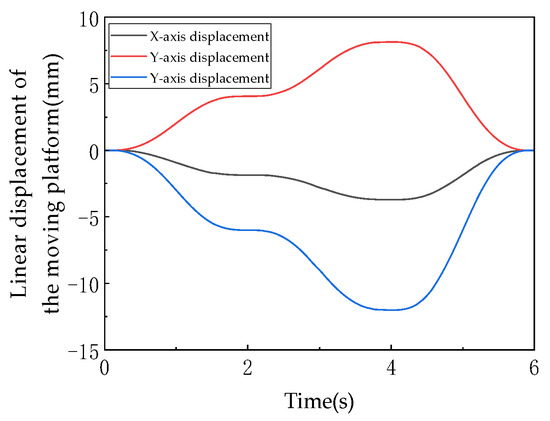
Figure 17.
The linear displacement of moving platform.
As shown in Figure 18, this graph records the angular displacement of the moving platform about the Z-axis over time, serving as a core characteristic indicator of the rotational degree of freedom in the 3T1R mode. During 0–2 s, the angular displacement decreases linearly from 0° to −30° (the negative sign indicates the direction of rotation), corresponding to active rotation about the Z-axis with U-joints unlocked in the 3T1R mode. From 2–4 s, the angular displacement remains constant at −30° (horizontal segment), during which the mechanism switches to the 3T mode (U-joints locked), constraining the rotational degree of freedom and validating that “the 3T mode is a zero-dynamic special case of the 3T1R mode with rotational DOF suppressed.” During 4–6 s, the angular displacement linearly increases from −30° back to 0°, corresponding to reset rotation in the 3T1R mode, forming a symmetric motion with the 0–2 s phase. The rotation angle values are calculated based on the rotation transformation matrix (Equation (5)), where and directly influence the determination of the moving platform’s hinge point coordinates The linear characteristics of the curves (0–2 s and 4–6 s) indicate that the rotational motion is constrained by the mechanism’s symmetric configuration (equilateral triangular fixed platform, 120°–distributed kinematic chains), ensuring uniqueness in rotation about the Z-axis. The absence of fluctuations or discontinuities in the curve confirms that the rotational DOF remains continuous and stable during mode transitions, with no interference from topological reconfiguration.
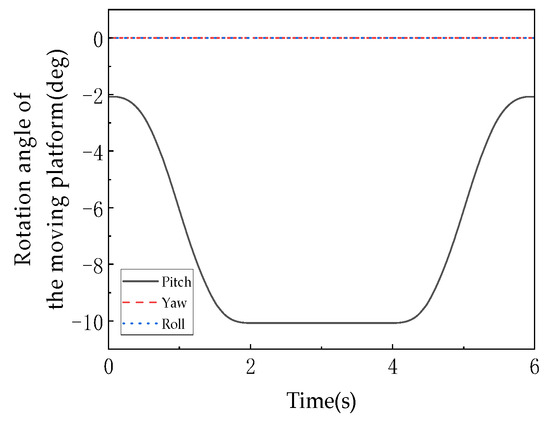
Figure 18.
The move the platform to the corner.
As shown in Figure 19, the velocity and angular velocity profiles of the moving platform are presented. These curves, derived as first-order time derivatives of the displacement and rotation angle data, reflect the dynamic smoothness of platform motion and serve as critical indicators for evaluating the mechanism’s dynamic performance. The linear velocity curves (corresponding to X, Y, Z axes) are derivatives of Figure 17 displacement curves. Peak velocities occur during 0–2 s and 4–6 s (e.g., Z-axis velocity peaks at ±8 mm/s), while velocities approach zero during 2–4 s (e.g., X-axis velocity maintained at ±1 mm/s), demonstrating the low-speed stability characteristic of pure translation in 3T mode. The angular velocity curve, derived from Figure 18 rotation profile, decreases from 0 deg/s to −0.5 deg/s during 0–2 s, remains at 0 deg/s during 2–4 s, and returns to 0 deg/s by 4–6 s, strictly synchronizing with rotational phases. The continuity of velocities and angular velocities (absence of spikes or discontinuities) validates the “motion continuity” conclusion in the document. The sinusoidal displacement planning (Equations (15) and (16)) ensures differentiable and continuous derivatives (i.e., ), meeting precision equipment requirements for low-impact motion (shock loads correlate with acceleration discontinuities).
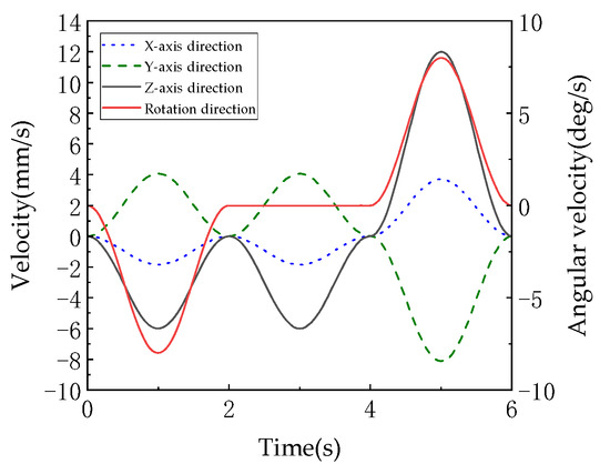
Figure 19.
The speed and angular velocity of the moving platform.
Figure 20 (angular displacement/velocity of U-joint axis) focuses on the U-joint’s rotational behavior, providing core evidence for the “1:1 linear coupling” characteristic. Comparing Figure 18 (platform rotation) with Figure 20 (U-joint rotation), the angular displacement curves perfectly overlap: both decrease from 0° to −30° during 0–2 s with identical slopes (about −15°/s), maintain −30° during 2–4 s, and recover to 0° during 4–6 s with matching slopes (about +15°/s). The synchronized angular velocity curves confirm that the moving platform’s rotation angle about the Z-axis and the U-joint’s rotation angle satisfy (proportionality factor = 1). As documented, this behavior originates from the mechanism’s symmetric configuration (120°-distributed kinematic chains) and spatial invariance of constraint couples (constraint moments remain perpendicular to the XY plane). The collinearity of U-joint and platform rotation axes (both along Z-axis) and fixed constraint moment direction enforce strict alignment without offset or misalignment, establishing an exact linear mapping.
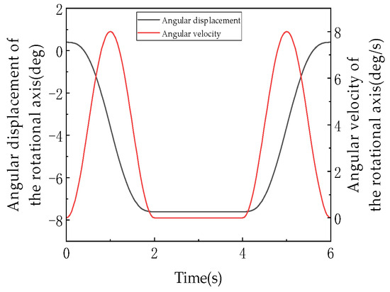
Figure 20.
The angular displacement and angular velocity of rotating shaft.
As shown in Figure 21, the linear displacements of the driving links are presented, illustrating the length variations in the three kinematic chain driving links (denoted as A, B, and C corresponding to chains 1, 2, and 3) over time, which reflect the coupling relationship between the driving inputs of the parallel mechanism and the pose of the moving platform. Driving links A and C exhibit monotonic increases from their initial 80 mm to 98 mm and 105 mm, respectively (with increments of 18 mm and 25 mm), demonstrating linear growth trends due to their primary roles in bearing support and driving functions during the 3T1R mode. Driving link B, starting from 70 mm, undergoes a “decline-rise” fluctuation (minimum 62 mm, maximum 72 mm, amplitude 10 mm) as it compensates for pose changes induced by the moving platform’s rotation during mode switching. The driving link displacements are derived from the closed-loop vector equation (Equation (13)), with their differentiated motions being necessary to satisfy the moving platform’s pose requirements. The continuous curves without abrupt transitions confirm the compatibility between the driving system and the topological reconfiguration (U-joint locking/unlocking) of the mechanism.

Figure 21.
The linear displacement of drive rod.
Figure 22 shows the linear velocities of the driving links, which are the first derivatives of the driving link displacements, reflecting the dynamic response characteristics of the driving system and serving as critical indicators for evaluating the control accuracy of the mechanism. The velocity curves align with the trends of the displacement curves in Figure 21: Links A and C maintain positive velocities (0–4 mm/s), indicating continuous extension, while Link B exhibits alternating positive and negative velocities (−2 to +3 mm/s), corresponding to its oscillatory displacement adjustment. Velocity peaks synchronize with the moving platform’s motion phases: higher peaks during 0–2 s and 4–6 s (3T1R mode, e.g., Link C reaching 6 mm/s) and lower peaks during 2–4 s (3T mode, e.g., Link A dropping to 1 mm/s), demonstrating dynamic matching between driving inputs and the moving platform’s pose requirements. The velocity variations (peak differences up to 3 mm/s) reflect the “multi-input, single-output” coupling nature—individual driving link motions must coordinate with the other two to satisfy the uniqueness constraint of the moving platform’s pose (determined by the spatial distribution of constraint couples in screw theory).
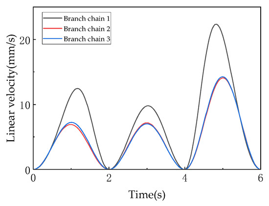
Figure 22.
The linear velocity of drive rod.
All curves exhibit continuous displacements and first-derivative continuity, verifying that the mechanism achieves shock-free, smooth transitions between 3T and 3T1R modes for both translational (X, Y, Z axes) and rotational (Z-axis) motions. This stems from sinusoidal pose planning (Equations (15) and (16)), ensuring continuous velocities and angular velocities suitable for low-impact applications like precision assembly and micro-manipulation. The smoothness of dynamic DOF reconfiguration is evidenced by the following: in 3T mode (2–4 s), the moving platform’s rotation angle remains constant (horizontal segment in Figure 18) and linear displacements stabilize (Figure 17), confirming effective constraint of rotational DOF; in 3T1R mode (0–2 s, 4–6 s), linear displacements and rotation angles change synergistically (aligned trends in Figure 17 and Figure 18), validating the efficacy of 3-translation + 1-rotation DOF. The two modes achieve topological reconfiguration via U-joint locking/unlocking, with the 3T mode acting as a “zero-rotation special case” of the 3T1R mode, reflecting logical continuity in DOF variation. The 1:1 linear coupling stability is quantitatively verified by the perfect synchronization between Figure 18 (platform rotation) and Figure 20 (U-joint rotation), confirming the strict linear relationship in 3T1R mode. This property arises from the mechanism’s symmetric configuration (120°-distributed chains), spatial invariance of constraint couples (perpendicular to the XY plane), and coaxial rotation (about the Z-axis), ensuring uniqueness of rotational DOF and avoiding singularities. The driving system’s coordinated adaptability is demonstrated by the differentiated motions of driving link displacements (Figure 21) and velocities (Figure 22), which are inherent outcomes of the parallel mechanism’s closed-loop constraints (Equation (13)). Curve continuity proves dynamic alignment between driving inputs and pose requirements, enabling high-precision trajectory tracking through “differentiated synergy.” In summary, the simulations comprehensively validate the 3RPUR metamorphic parallel mechanism’s core performance at the kinematic level: dynamic reconfigurability, motion continuity, coupling stability, and driving coordination, providing quantitative foundations for its application in mobile robotics.
6. Application Research of the Mechanism
The fundamental goal and advantage of this design is to actively exploit the mechanism’s intrinsic symmetries (and induced asymmetries) through strategic combinations of joint locking and unlocking, thereby achieving dynamic functionality switching. A 3RPUR mobile robot is designed with the 3RPUR metamorphic parallel mechanism as its core component, featuring a symmetric fixed platform-kinematic chain-moving platform configuration. In 3T mode (three translations), when all U-joints of the three kinematic chains are locked, the constraint couples form a spatially concurrent constraint system, restricting the moving platform to pure translational degrees of freedom along the X, Y, and Z axes, making it suitable for operation on flat surfaces such as indoor corridors or factory floors, where smooth movement is achieved through controlled extension/retraction of prismatic joints (P) while leveraging the mechanism’s workspace symmetry (XY-plane central symmetry and XZ/YZ-plane near-symmetry) to ensure precision in straight-line motion and steering. In 3T1R mode (three translations plus one rotation), when one U-joint is unlocked, its constraint couple disappears while the remaining two chains’ constraint couples form a coplanar constraint system, releasing the moving platform’s rotational degree of freedom about the Z-axis, enabling the robot to adapt to complex terrains like steps, gravel paths, or shallow ditches through platform posture adjustments such as unilateral leg lifting or body tilting, with the 1:1 linear coupling between platform rotation and U-joint angles ensuring precise and controllable posture adjustments while preventing overturning risks caused by motion deviations, as validated through simulation experiments of the moving platform. The robot’s metamorphic capability allows dynamic switching between 3T and 3T1R modes via U-joint locking/unlocking, providing versatile operation in both structured and unstructured environments and offering a novel solution for mobile robots operating in complex terrains with broad potential applications in exploration, rescue operations, and industrial scenarios.
As shown in Figure 23, the linear displacement of the mobile robot’s moving platform (Figure 23a) demonstrates the following: along the Z-axis (green line), displacement decreases from 0 mm to −15 mm vertically (e.g., “sinking” or “climbing” during obstacle crossing); along the X-axis (black line), displacement reduces from 0 mm to −10 mm horizontally (e.g., leftward movement for path adaptation), while the Y-axis (blue line) shows near-zero displacement, indicating negligible translation and motion concentrated in the X-Z plane, consistent with the 3T1R’s “three-translation synergy” (Y-axis serving as auxiliary constraint direction). The smooth, continuous displacement curves ensure stable robot movement (e.g., jerk-free obstacle avoidance). The moving platform’s linear/angular velocities (Figure 23b) reveal: periodic fluctuations in X/Z-axis velocities (peaking at ±6 mm/s and ±8 mm/s, respectively), matching the “acceleration–deceleration” cycles of displacement (e.g., dynamic adjustments during obstacle crossing); near-zero Y-axis velocity aligns with displacement trends. Angular velocity occurs solely about the Z-axis (yaw, black dashed line peaking at ±5 deg/s), corresponding to 3T1R’s “one rotation”, while roll (X) and pitch (Y) angular velocities remain near zero, verifying the mechanism’s constraint capability on non-target rotations (preserving only Z-axis DOF). Continuous, shock-free velocity/angular velocity profiles meet low-vibration requirements (preventing internal component damage), with suppressed non-target rotations demonstrating precise DOF constraint. Platform attitude angles (Figure 23c) show: yaw angle (black line) decreasing from 0° to −20°, representing active rotation in 3T1R mode (corresponding to variation in configuration diagrams for Z-axis steering); pitch (red) and roll (blue) angles maintain minimal changes (near 0°), as the symmetric configuration (equilateral triangular base, 120°-distributed chains) strictly constrains X/Y-axis rotations, preventing attitude instability (e.g., no tilting/rolling during obstacle crossing). The “single-axis dominance (Z) with dual-axis constraint (X/Y)” pattern validates 3T1R’s DOF design objectives, ensuring directional turning stability and obstacle-crossing posture control. Kinematic chain differential extensions (actuator motions) fully synchronize with the platform’s “3T+1R” movement, with configuration diagrams matching curve trends, confirming simulation validity. Precise DOF control—significant Z-axis rotation with near-zero pitch/roll angles—demonstrates strong non-target DOF constraint, ideal for directional motion and attitude stability (e.g., narrow passage maneuvering, slope navigation). The smooth motion characteristics (continuous displacement/velocity/angular velocity) ensure shock-free operation, suitable for disaster response and exploration applications.
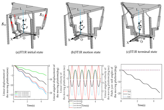
Figure 23.
Motion simulation of 3RPUR variable cell parallel mechanism mobile robot.
7. Conclusions
The analysis of the 3-RPUR parallel mechanism examines the degree-of-freedom (DOF) variation under the locking/unlocking of universal joints (U-joints) and explores its motion continuity. By leveraging the mechanically reconfigurable characteristics of lockable U-joints, switching between two motion modes—3T (three translations) and 3T1R (three translations and one rotation) is achieved. The mechanism adopts a symmetric arrangement of three RPUR kinematic chains, with electromagnetic braking modules selectively locking one rotational DOF of the U-joints to enable active topological reconfiguration.
Simulation experiments validate the DOF variation, continuity, and motion consistency of the metamorphic mechanism. In the 3T1R mode, the mechanism exhibits a unique DOF coupling relationship. The rotation angle of the moving platform about the Z-axis shows a strict linear correlation with the U-joint rotation angle, reflecting a coupled “pose–joint angle synchronization” behavior. This 1:1 coupling is determined by the symmetric topology of the mechanism and the geometric constraints of the kinematic chains. Notably, this coupling ensures the uniqueness and continuity of the rotational DOF.
A mobile robot designed with the 3RPUR metamorphic parallel mechanism as its core demonstrates adaptive capabilities in complex terrains due to its unique reconfigurability and motion performance. The robot employs a symmetric “fixed platform–kinematic chain–moving platform” layout, dynamically switching motion modes via U-joint locking/unlocking mechanisms. It can adjust its posture (e.g., unilateral leg lifting, body tilting) to navigate obstacles such as steps, gravel paths, and shallow trenches. This approach provides a novel technical solution for mobile robots operating in complex environments, offering broad potential for research and applications in the field.
Author Contributions
Conceptualization, S.Q. and C.L.; methodology, S.Q. and C.L.; validation, H.W. and Z.Q.; formal analysis, S.F. and Q.W.; investigation, R.L. and T.S.K.; data curation, W.Y. and E.L.S.; writing—original draft preparation, C.L.; writing—review and editing, S.Q.; supervision, S.Q.; project administration, S.Q.; funding acquisition, S.Q. All authors have read and agreed to the published version of the manuscript.
Funding
This research was funded by the Central Government-Guided Local Development Fund Project, grant number YDZJSX2025D042; the Key R&D Program of Shanxi Province, grant number 202202150401018; the Basic Research Program of Shanxi Province, grant number 20250302124220; and the State Key Laboratory of CAD/CAM of Zhejiang University, grant number A2325.
Data Availability Statement
The original contributions presented in the study are included in the article; further inquiries can be directed to the corresponding author.
Conflicts of Interest
The authors declare no conflicts of interest.
References
- Napoleone, A.; Andersen, A.-L.; Brunø, T.D.; Nielsen, K. Towards human-centric reconfigurable manufacturing systems: Literature review of reconfigurability enablers for reduced reconfiguration effort and classification frameworks. J. Manuf. Syst. 2023, 67, 23–34. [Google Scholar] [CrossRef]
- Zhang, Y.; Zhao, J.; Zhao, Z.; Kang, R.; Dai, J.; Song, Z. Design and Analysis of a Parallel Cable-Driven Lower Limb Rehabilitation Robot for Multi-Joint Training. J. Mech. Eng. 2024, 60, 111–122. [Google Scholar]
- Kang, X.; Dai, J. Theoretical difficulties and research progresses of mechanism reconfiguration in mechanisms. China Mech. Eng. 2020, 31, 57–71. [Google Scholar]
- Wei, J.; Dai, J.S. Reconfiguration-aimed and manifold-operation based type synthesis of metamorphic parallel mechanisms with motion between 1R2T and 2R1T. Mech. Mach. Theory 2019, 139, 66–80. [Google Scholar] [CrossRef]
- Han, B.; Yang, M.; Luo, M.; Li, M.; Yao, J.; Zhao, Y. Design and Analysis of a Single-Drive Spatially Deployable Metamorphic Capture Manipulator. J. Mech. Eng. 2025, 61, 30–43. [Google Scholar]
- Jia, G.; Li, B.; Dai, J. Metamorphic Block Mechanisms: Design and Kinematic Analysis of Metamorphic Block Mechanisms Constructed by Cylinder/Cone Cutting and Linking. J. Mech. Eng. 2023, 59, 24–35. [Google Scholar]
- Wang, L.; Zhang, J.W.; Zhang, D. A Review on Reconfigurable Parallel Mechanisms: Design, Analysis and Challenge. Engineering 2025, 47, 100–116. [Google Scholar] [CrossRef]
- Deutsches Zentrum fuer Luft und Raumfahrt, eV. Protective Device for an Effector of a Manipulator, Device for Manipulating Workpieces, and a Method for Actuating a Device for Manipulating Workpieces. U.S. Patent 201716085783A, 15 November 2022. [Google Scholar]
- Qu, H.; Guo, S.; Zhang, Y. A novel relative degree-of-freedom criterion for a class of parallel manipulators with kinematic redundancy and its applications. Proc. Inst. Mech. Eng. Part C J. Mech. Eng. Sci. 2017, 231, 4227–4240. [Google Scholar] [CrossRef]
- Yang, L.; Li, Y.; Yao, Y.; Kong, X. Type synthesis of multi-mode mobile parallel mechanisms based on refined virtual chain approach. Mech. Mach. Theory 2020, 152, 103908. [Google Scholar] [CrossRef]
- Kong, X. Type Synthesis of Three-Degree-of-Freedom Spherical Parallel Manipulators. Int. J. Robot. Res. 2004, 23, 237–245. [Google Scholar] [CrossRef]
- Che, L.; Huang, X.; Peng, S.; Wang, Y.; Lan, J. Kinematic performance analysis of a 2RPU-RPUR parallel mechanism without parasitic motion. J. Mech. Transm. 2025, 49, 48–59. [Google Scholar]
- Hao, Y.; Li, R.; Sun, X.; Yao, Y. Design and Motion Mode Analysis of a Reconfigurable Cube Mechanism. J. Mech. Eng. 2020, 56, 120–127. [Google Scholar]
- Park, J.; Lee, S.; Kim, Y.; Yi, B.-J. Dynamic constraint modeling framework. Int. J. Robot. Res. 2022, 41, 831–856. [Google Scholar]
- Wang, L.; Cheng, Y.; Zhao, J.; Zhao, T.; Zhao, Y. Vision-based control of 3-RPUR. Robot. Comput.-Integr. Manuf. 2024, 85, 102612. [Google Scholar]
- Kim, B.; Um, T.T.; Suh, C.; Park, F.C. Tangent bundle RRT: A randomized algorithm for constrained motion planning. Robotica 2016, 34, 202–225. [Google Scholar] [CrossRef]
- Nakamura, T.; Ota, Y.; Fukushima, H.; Ding, X.; Suzumori, K. Dynamic performance evaluation of reconfigurable parallel mechanisms. IEEE/ASME Trans. Mechatron. 2023, 28, 1589–1601. [Google Scholar]
- Di Leva, R.; Gattringer, H.; Müller, A.; Carricato, M. Force and time-optimal trajectory planning for dual-arm unilateral cooperative grasping. Mech. Mach. Theory 2024, 201, 105729. [Google Scholar] [CrossRef]
- Li, Q.; Chen, W.; Wang, T.; Li, J.; Zhang, H. Clinical application of reconfigurable surgical robots. Int. J. Med. Robot. 2024, 20, e2588. [Google Scholar]
- Jia, P.; Li, D.; Lei, Z.; Zhang, Y.; Yang, C. Configuration and Kinematic Analysis of a 3(Ra)PS Metamorphic Parallel Mechanism. Trans. Chin. Soc. Agric. Mach. 2022, 53, 443–450. [Google Scholar]
- Feng, S.; Qu, S.; Li, R.; Yao, W.; Ma, C. Design of a 3(rU)PU Metamorphic Parallel Mechanism Based on Variable-Axis Kinematic Pairs. China Mech. Eng. 2025, 1–12. [Google Scholar]
- Yu, H.; Zeng, Z.; Guo, Z. Synthesis Design Method for Lower-Mobility Metamorphic Parallel Mechanisms. J. Harbin Inst. Technol. 2018, 50, 42–49. [Google Scholar]
- Chang, B.; Jin, G.; Dai, J. Configuration Synthesis of Metamorphic Mechanisms Based on Variable-Constraint Screw Theory. J. Mech. Eng. 2014, 50, 17–25. [Google Scholar] [CrossRef]
- Ye, W.; Li, Q. Type synthesis of lower mobility parallel mechanisms: A review. Chin. J. Mech. Eng. 2019, 32, 38. [Google Scholar] [CrossRef]
- Wei, J.; Yu, B.; Liu, C.; Song, J.; Zhang, J.; Meng, C. Grassmann line geometry based configuration synthesis of equivalent UU parallel mechanisms with two virtual center-of-motion. Mech. Mach. Theory 2023, 181, 105208. [Google Scholar] [CrossRef]
- Qu, S.; Guo, Z. Research Status and Analysis of Decoupling Mechanisms. J. Mech. Transm. 2022, 46, 170–176. [Google Scholar]
- Yu, J.; Liu, X.; Ding, X.; Dai, J. Mathematical Foundations of Robotic Mechanisms; China Machine Press: Beijing, China, 2008; pp. 32–34+169+193. [Google Scholar]
- Yu, J.; Liu, K.; Kong, X. State of the Art of Multi-Mode Mechanisms. J. Mech. Eng. 2020, 56, 12–27. [Google Scholar]
- Li, C.; Wang, Y.; Zheng, Y.; Wang, F.; Wang, D. Inverse Position Solution and Reachable Workspace Analysis of 2-UPS/RRR Parallel Mechanism. J. Mech. Transm. 2025, 49, 31–38. [Google Scholar]
- Ma, N. Kinematic Analysis and Simulation of a Novel 3-RPUR Parallel Mechanism. Ph.D. Thesis, Yanshan University, Qinhuangdao, China, 2007. [Google Scholar]


Disclaimer/Publisher’s Note: The statements, opinions and data contained in all publications are solely those of the individual author(s) and contributor(s) and not of MDPI and/or the editor(s). MDPI and/or the editor(s) disclaim responsibility for any injury to people or property resulting from any ideas, methods, instructions or products referred to in the content. |
© 2025 by the authors. Licensee MDPI, Basel, Switzerland. This article is an open access article distributed under the terms and conditions of the Creative Commons Attribution (CC BY) license (https://creativecommons.org/licenses/by/4.0/).