Article

Mild Hybrid Powertrain for Mitigating Loss of Volumetric Efficiency and Improving Fuel Economy of Gasoline Vehicles Converted to Hydrogen Fueling

by
Sebastian Bibiloni
1,
Adrian Irimescu
2,*,
Santiago Martinez-Boggio
1,
Simona Merola
2 and
Pedro Curto-Risso
1
1
Instituto de Ingeniería Mecánica y Producción Industrial (IIMPI), Facultad de Ingeniería, Julio Herrera y Reissig 565, Montevideo 11300, Uruguay
2
Institute of Science and Technology for Sustainable Energy and Mobility STEMS-CNR, Via G. Marconi 4, 80125 Napoli, Italy
*
Author to whom correspondence should be addressed.
Machines 2024, 12(6), 355; https://doi.org/10.3390/machines12060355
Submission received: 11 April 2024 / Revised: 17 May 2024 / Accepted: 19 May 2024 / Published: 21 May 2024
(This article belongs to the Special Issue Advanced Engine Energy Saving Technology)

Abstract

:
The pursuit of sustainable and environmentally friendly transportation has led to the exploration of alternative fuel sources, among which hydrogen stands out prominently. This work delves into the potential of hydrogen fuel for internal combustion engines (ICEs), emphasizing its capacity to ensure the required performance levels while concurrently enhancing overall efficiency. The integration of a mild hybrid powertrain in a small size passenger car was considered for obtaining a twofold advantage: mitigating power loss due to low volumetric efficiency and increasing fuel economy. A comprehensive approach combining 0D/1D modeling simulations and experimental validations was employed on a gasoline-powered small size ICE, considering its conversion to hydrogen, and mild hybridization. Vehicle simulations were performed in AVL Cruise M and validated against experimental data. Various electric motors were scrutinized for a small size battery pack typical of mild hybrid vehicles. Furthermore, the paper assesses the potential range achievable with the hydrogen-powered hybrid vehicle and compares it with the range reported by the manufacturer for the original gasoline and pure electric version. In terms of global results, these modifications were found to successfully improve efficiency compared to baseline gasoline and hydrogen fueling. Additionally, performance gains were achieved, surpassing the capabilities of the original gasoline vehicle despite its intrinsic volumetric efficiency limitations when using hydrogen. Along with the conversion to hydrogen and thus zero-carbon tail-pipe emissions, incorporating a Start/Stop system, and the integration of mild hybrid technology with energy recuperation during braking, overall efficiency was enhanced by up to 30% during urban use. Furthermore, the hybridization implemented in the H2 version allows an autonomy comparable to that of the electric vehicle but with evident shorter refilling times. Specific aspects of the 48 V battery management are also scrutinized.

1. Introduction

With current restrictions and global objectives in climate change mitigation and GHG emissions reduction, it is increasingly imperative to explore alternatives to traditional fuels for vehicle propulsion. A clear example of these restrictions is the European Union (EU), which aims to achieve zero GHG emissions by 2050 through the Green Deal program with an emphasis on transportation [1,2]. Among the alternatives, synthetic liquid fuels and electric vehicles are recognized [3], and more recently, H2 propulsion has stood out [4], either through fuel cells for electric power generation or through direct hydrogen combustion. For this reason, it is crucial to conduct studies comparing different propulsion systems for various types of vehicles and their respective uses. This will enable the development of future generations of vehicles that are more efficient and capable of delivering the best possible performance according to their type and function. Studies such as [5], where electric, diesel, and green fuel blend propulsion systems applied in trucks are evaluated, are essential for analyzing aspects such as emissions, economy, performance, and other relevant parameters in their assessment. In this context, the proposal emerges to carry out retrofitting of a vehicle for H2 use, allowing carbon dioxide (CO2) propulsion. This would be achieved without the need for a complete vehicle reconstruction, thus avoiding pollution associated with such a process, as well as cost-effective zero carbon mobility Despite hydrogen being a well-known fuel, the development of a H2 propulsion powerplant is in progress despite the lack of literature compared to traditional fuels mainly in internal combustion engines.
In the field of sustainable transportation, the utilization of hydrogen as a fuel source has emerged as a beacon of promise, offering a viable solution to curb environmental degradation and reduce dependence on traditional fossil fuels [6]. Hydrogen, when harnessed to power both fuel cells (FCs) and internal combustion engines (ICEs), presents a versatile and eco-friendly alternative. It also shows advantages that avoid complications seen in electric vehicle (EV) batteries [7]. Despite their potential, FCEVs encounter various challenges that currently impede their widespread adoption, with cost being one of the main aspects compared to both ICEs and EVs [8] along with their sensitivity to the quality of hydrogen [9]. Additionally, even small amounts of water, while only slightly reducing efficiency, can lead to damage if they carry potassium or sodium ions [10]. The composition of gases dissolved in hydrogen is directly influenced by the production method, varying between electrolysis and steam reforming (SMR) with natural gas, among others. Another critical concern with FCs is their wear during driving cycles, directly impacting efficiency and voltage drop, subsequently affecting vehicle consumption and performance [11]; their anticipated lifespan is approximately 5000 h [12]. It is also crucial to underscore that the environmental cost associated with the production of these cells is considerably large in comparison with the ICE [13], presenting a substantial impediment to the feasibility of this approach. The intricate balance between the need for intermittent replacements for optimal FC operation and the environmental implications inherent in cell production poses a challenge that demands careful consideration and strategic solutions for sustainable fuel cell technology integration [14].
The main advantage of hydrogen-fueled internal combustion engines (H2-ICEs) is the possibility of retrofitting current ICEs that use other fuels such as gasoline [15,16]. This environmental advantage is significant as it involves simply replacing some parts rather than creating an entire new powertrain for a vehicle [17]. The main disadvantage of H2-ICE is the emission of Nitrogen Oxide (NOx). However, with proper design, these NOx emissions can be brought very close to zero without a significant loss of power and efficiency [18,19]. This can be achieved through various strategies to control combustion, such as the Start of Injection (SOI), ignition timing, cylinder geometry and arrangement, turbocharging, Exhaust Gas Recirculation (EGR), and injection type. All these factors are crucial and impact both NOx emissions and Brake Thermal Efficiency (BTE) and Brake Mean Effective Pressure (BMEP). Another crucial factor is the lean combustion, aiming to control combustion temperatures and reduce emitted NOx [18,20]. Depending on the engine design, whether it is created from scratch or retrofitted, the type of fuel injection that can be used includes Port Fuel Injected (PFI) and Direct Injection (DI). It is a reality that the DI system allows more options for combustion control, enabling the generation of a homogeneous air–fuel mixture or stratification. Additionally, it improves volumetric efficiency and decreases the engine’s pumping work. This DI system presents several advantages in the engine compared to PFI technology [21]. However, ongoing research is still being conducted to improve its effects on engines, allowing the enhancement of parameters such as efficiency, performance, power, and emissions. Therefore, a potential future research direction could involve conducting tests with various injections seeking different air–fuel mixtures, similar to the study in [22] but evaluating with hydrogen. Fueling through PFI is the simplest and cheapest option for retrofitting [23,24]. However, this injection system has certain associated problems in volumetric efficiency and abnormal combustion [20], which tends to limit the power and efficiency of engines compared to DI, especially at low engine speeds. Additionally, combustion control is more complex and limited, especially at low engine speeds [24,25]. Anomalies in combustion, such as knock, autoignition, and Cycle-to-Cycle Variability (CCV), are among the challenges due to the low activation energy required to initiate combustion and the wide flammability limits, complicating both hydrogen manipulation and combustion control. For these reasons, engine control strategies are crucial to achieve clean, efficient, and effective operation. It is important to clarify that the wide flammability limits are positive as well as negative. While it makes hydrogen a hazardous fuel to work with, it allows playing with stratification in DI, providing an advantage. There are also other green fuels (e-fuels) that are cleaner and easier to produce than hydrogen, such as Syngas. However, these fuels have several challenges for achieving good combustion and lower efficiencies compared to H2-ICE efficiencies [26]. In the case of Syngas, efficiencies are around 20%, while H2-ICE efficiencies range from 40% to even 45%. Although this efficiency within ICE is high, it is lower than FCs. However, it is more constant in ICE, as they do not undergo as many changes. It is also possible to mix hydrogen with other fuels to reduce GHG emissions [27]. While the retrofitting of internal combustion engines (ICEs) with hydrogen fuel offers significant environmental advantages, it is important to acknowledge the practical challenges associated with hydrogen storage systems. The adoption of hydrogen-fueled ICEs involves considerations beyond the engine conversion itself, particularly concerning the integration of hydrogen storage technologies into existing vehicle architectures. Hydrogen storage systems, notably type IV tanks operating at high pressures, introduce constraints on vehicle design due to their volumetric and weight limitations. The low density of hydrogen needs larger storage volumes to achieve comparable energy densities to conventional fuels, impacting factors such as available cargo space and vehicle weight distribution. Additionally, the reinforced construction required to withstand high pressures contributes to the overall weight of the storage system, posing challenges for vehicle manufacturers striving to optimize performance and efficiency. Despite these challenges, ongoing research and development efforts are focused on improving the efficiency and practicality of hydrogen storage technologies with advancements in tank materials, design optimization, and alternative storage methods aimed at addressing volumetric and weight constraints. By addressing these technical challenges, the feasibility and adoption of hydrogen-fueled ICEs can be further enhanced, contributing to the transition toward sustainable transportation solutions.
This particular aspect of hydrogen has prompted numerous studies related to the implementation of other CO2-neutral or low-carbon emission fuels derived from hydrogen. These fuels also emerge as a viable option for decarbonizing transportation by enabling simpler fuel storage systems with reduced volume and weight requirements. A study conducted by [28] thoroughly examines some of these fuels in internal combustion engines, providing strong support for their adoption in vehicles. This study concludes that the best low-carbon fuel that could be produced from green hydrogen is HCNG (hydrogen-enriched compressed natural gas), after evaluating various aspects to reach this conclusion.
Given these limitations, a simple conversion would result in inferior performance. To address this situation, various types of potential hybridizations were analyzed for a small size passenger car. Considering the dimensions of the vehicle, clearances, and the propulsion system it utilizes, the decision was made to implement a mild hybrid electric vehicle P0 (MHEV) hybridization. It was estimated that this would be the optimal hybridization for this vehicle. Nevertheless, there are several different hybridization configurations that lead to varying effects on vehicles. Therefore, a potential avenue for future work could involve evaluating various hybridizations (even if any configuration would have a positive impact) to determine the optimal one for this vehicle, as discussed [29]. The hybridization is implemented with electric motors of various sizes. This approach aims to assess improvements in consumption and performance with the goal of achieving a conversion that maintains or surpasses the performance of the gasoline vehicle while reducing energy consumption, especially in urban conditions, for which this smaller-sized vehicle is primarily designed. The significance of this study lies in its demonstration of the potential of mild hybridization to enhance both the range and performance of small urban passenger vehicles equipped with hydrogen-powered internal combustion engines (ICEs). Notably, this research addresses a critical limitation in hydrogen propulsion systems by effectively overcoming power deficiencies attributed to volumetric efficiency constraints. Innovatively, it is converted a gasoline engine to hydrogen power, showcasing the adaptability of mild hybrid technology to mitigate the inherent challenges associated with hydrogen ICEs. By seamlessly integrating 48V mild hybridization into the vehicle’s powertrain, this work intended to show the capabilities of the proposed technology in terms of performance and range suitable for urban commuting. The utilization of mild hybrid technology in conjunction with hydrogen power represents a promising avenue for achieving enhanced efficiency and reduced environmental impact in small passenger vehicles.

2. Materials and Methods

2.1. Hydrogen Engine Simulation

The selected power unit for the fuel change corresponds to a small size passenger car that in its standard version features a turbocharged gasoline engine. Table 1 provides additional relevant technical specifications of the unit. Numerical simulations were implemented for evaluating the specifics of switching from one fuel to another. Engine modeling was conducted through 0D/1D simulation, considering measurements obtained from a disassembled unit and original equipment manufacturer (OEM) data such as the default turbocharger control settings.
For the hydrogen conversion, a previous version of the 0D/1D engine model was adapted as illustrated in Figure 1. Key modifications included the addition of a second PFI system for H2 injection and adjusting ignition timing to account for the difference in laminar flame speed between the two fuels [25]. The search for the optimal ignition point was carried out using a PID controller to maximize efficiency; an if–then–else condition was used for setting a limit on the spark advance if knocking was predicted. Additionally, a PID controller was implemented for the waste-gate controlled turbocharger to regulate the compressor pressure ratio and optimize ICE performance. These components are highlighted in Figure 1 along with the throttle controller that was used during part load operation.
The main structure and effectiveness of the engine model was detailed in recent works of the authors (see [25,27,30] for more information) aimed to evaluate and optimize key parameters such as nominal power, range, fuel system requirements, and the effect of cycle-to-cycle variability (CCV) on performance, among others. The focus of previous activities was on improving hydrogen ICE performance without neglecting the cost reduction in both operation and engine construction, which are critical factors in small passenger vehicles. Throttle angle and fuel injection were also managed through another PID controller, using shaft power as a feedback parameter. This independent controller has a 90-degree limit for the throttle during boosted operation, avoiding contradictory situations and achieving stable operations. All previous results represented the starting point for the vehicle hybrid design that is the aim of the present work.
For the operation of the injection controller, a target value for the exhaust lambda sensor was set, assuming a rich feed under full load conditions with gasoline and stoichiometry for the rest of the operating points, thus rendering it fully compatible with the standard three-way catalytic converter. To appropriately incorporate fuel chemistry effects, a predictive combustion model (SI Turbulent Flame Combustion Model) was used. An interesting comparison between different combustion models can be seen in [31]. SI Turb offers users a comprehensive two-zone model that includes entrainment and burn-up aspects. Key features of this system include the prediction of combustion rates based on in-cylinder conditions, flexibility in adjusting spark timing and locations, consideration of fuel properties and mixture composition, incorporation of turbulence effects such as tumble and swirl, and ensuring both high accuracy and fast run times for simulations. Additionally, SI Turb provides detailed analysis capabilities covering knock, cycle-to-cycle variability (CCV), and emissions, along with access to fast-running models for quicker assessments. Overall, SI Turb provides a sophisticated combustion modeling solution with a focus on accuracy, efficiency, and detailed analysis across various engine parameters. The flow-based heat transfer sub-model was used for better reflecting the related effects of “faster” H2 combustion evolution [31].
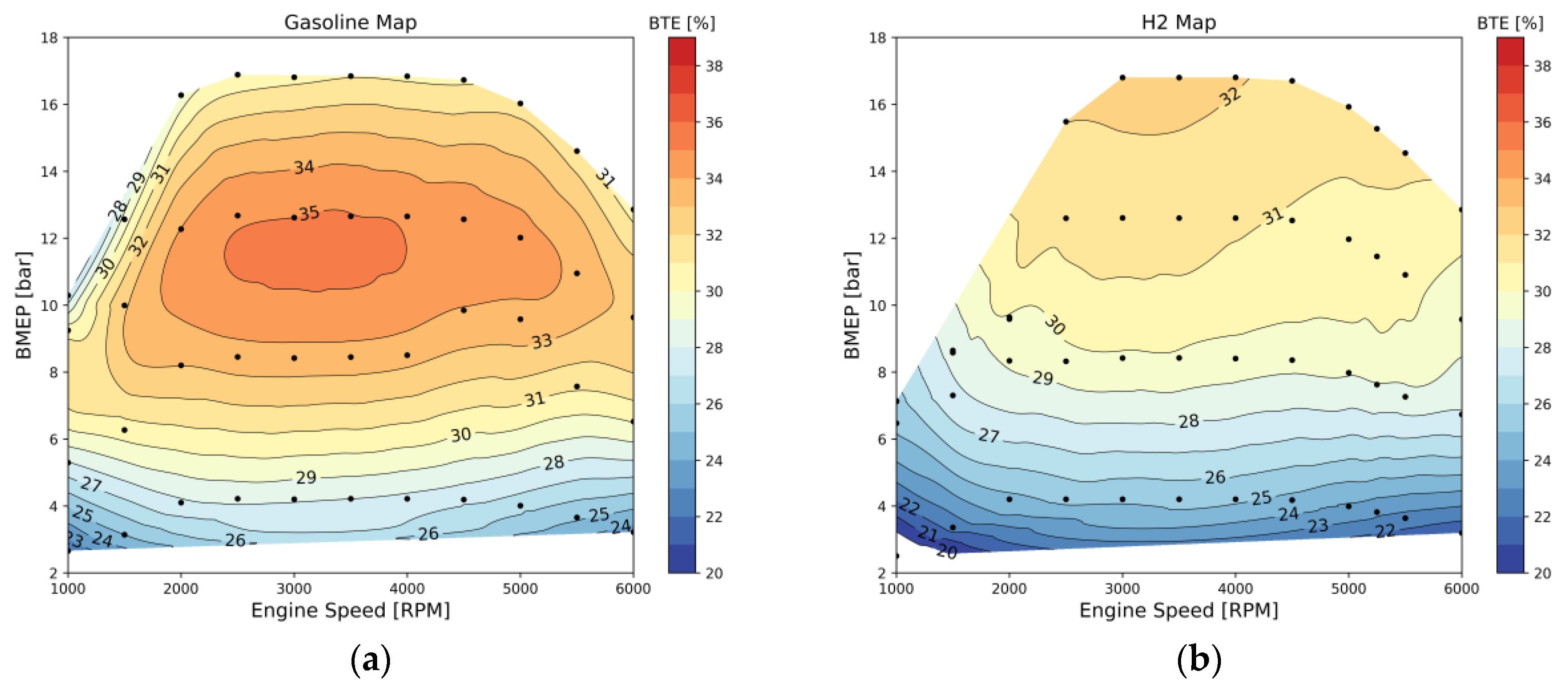
One of the main challenges associated with fuel conversion is the impact of hydrogen’s low volumetric energy density. This results in a decrease in specific power and, consequently, lower efficiency at various engine operating points than gasoline. It also modifies the energy conversion efficiency map, as evidenced in Figure 2. In this figure, several differences can be observed between maps (a) and (b), including the full load curve, where hydrogen experiences a lack of power, the brake thermal efficiency at different points, and the shape of the efficiency iso-curves. Reduced volumetric efficiency results in lack of power and therefore requires higher boost levels for obtaining the same power output. The difference in conversion efficiency observable when comparing Figure 2a,b is mostly due to the fact that extremely high laminar flame speed results in quick flame propagation and increased heat loss [31].

2.2. Mild Hybrid Vehicle Model

The initial phase involved creating and validating the non-hybrid gasoline model to formulate the hydrogen hybrid version of the vehicle. Subsequently, versions were developed for the non-hybrid gasoline vehicle, including hydrogen, hydrogen hybrid configuration, and pure electric models. The hybrid was meticulously designed to ensure that the improvements in fuel economy for the P0-type mild hybrid electric vehicle (MHEV) aligned precisely with the anticipated outcomes for this specific hybrid configuration. After successfully validating the commercial gasoline vehicle, the necessary adjustments were implemented in the model to facilitate its transformation into a hydrogen-powered vehicle.
The vehicle simulations were performed in AVL Cruise M from AVL GmbH. When constructing the 0D/1D simulation model for the standard gasoline version, the starting point involved modeling all significant components of the original vehicle. This encompassed utilizing manufacturer-provided data, incorporating measurements, and making estimates, such as determining the position of the center of mass. It is crucial to note that in simulations of this nature, the center of mass position has a limited impact on the overall vehicle behavior. The engine was characterized as an entity with defined parameters, including maximum power, fuel consumption map, and intrinsic features like the number of cylinders, displacement, and inertias; some of these detailed in Table 2.
The battery capacities for both the electric vehicle (EV) and mild hybrid electric vehicle (MHEV) were chosen based on established industry standards and common practices. For the EV, the battery capacity corresponds to the standard battery utilized by the manufacturer of the Smart Fortwo Electric [32], ensuring consistency with industry benchmarks and facilitating direct comparability with commercially available electric vehicles. Similarly, the battery capacity for the MHEV aligns with industry standards for small hybrid electric vehicles, enabling meaningful comparisons and ensuring relevance to real-world automotive applications.
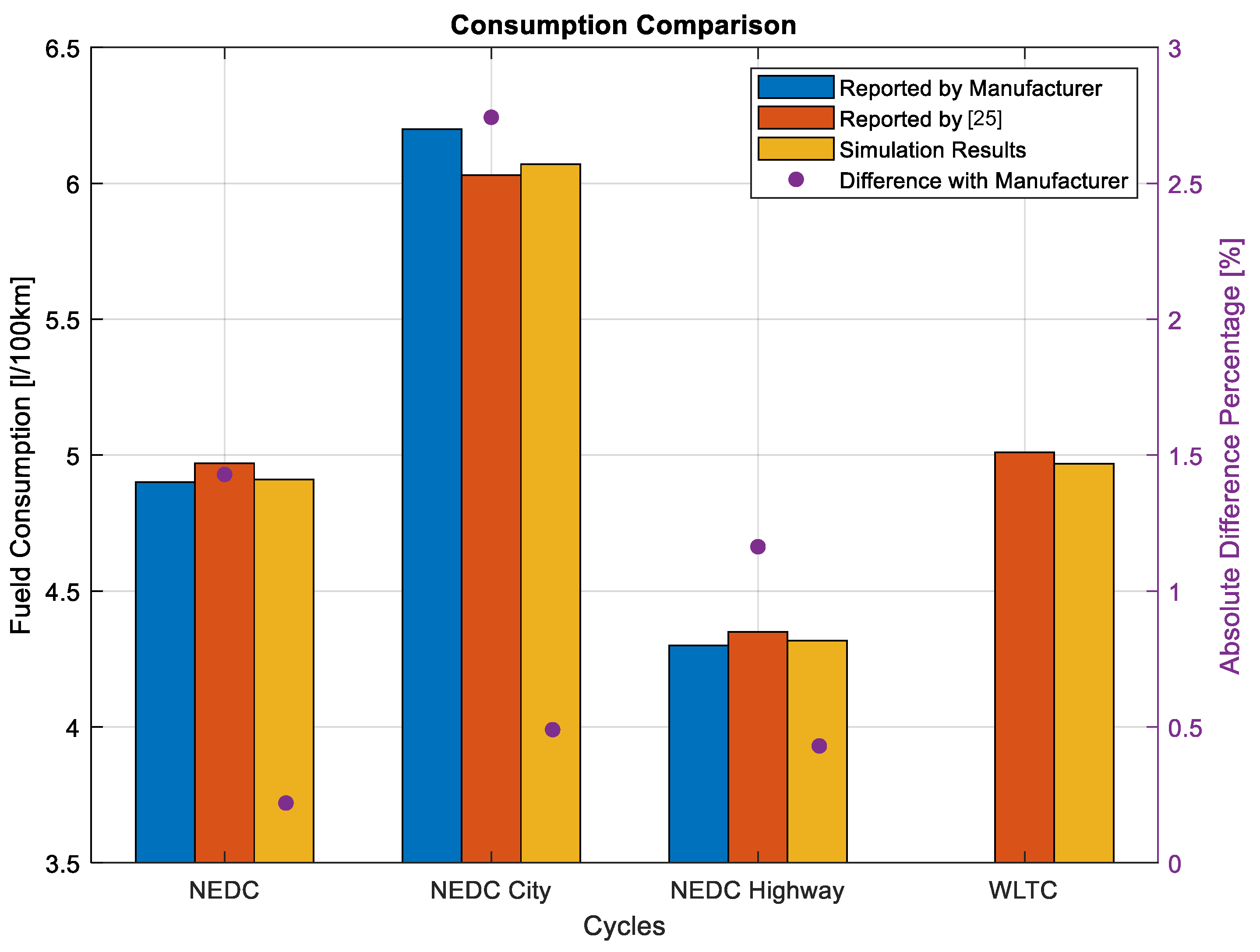
Model validity was confirmed through comparison of fuel consumption against data published by the manufacturer [32] and in earlier studies such as [29]; the comparison is shown in Figure 3. It illustrates the validity of the numerical results confirmed by the difference below 1% compared to the OEM data as well as the coherence between various versions of the model.
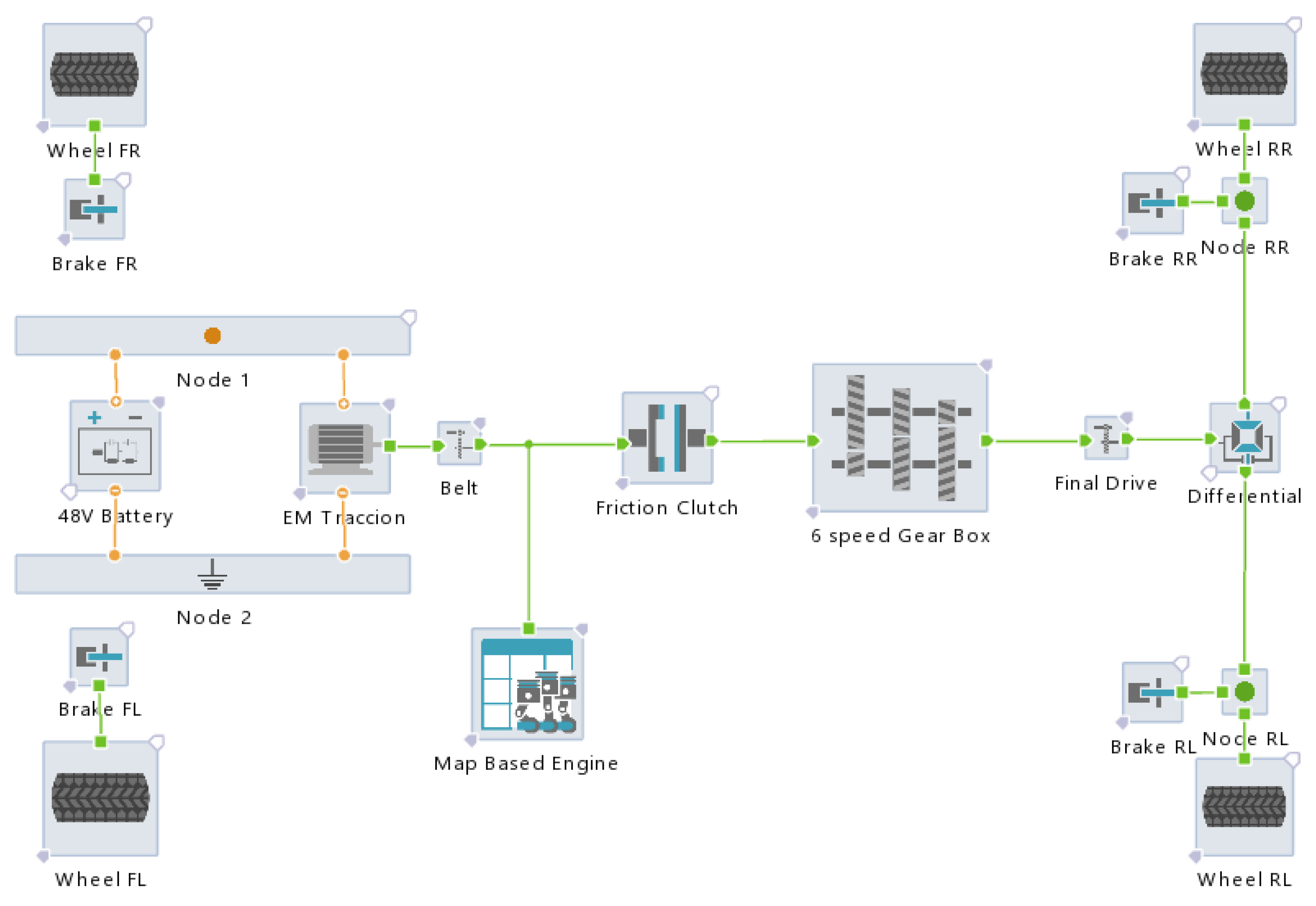
For the hybrid configurations a Start/Stop system was added for reducing fuel consumption. It was extended to the conventional model, incorporating a modification that introduced a small battery (refer to Table 2), which is a characteristic common in P0-type MHEVs. Additionally, an electric motor (EM) was integrated and connected to the ICE crankshaft via a belt. A control strategy was implemented, emphasizing energy recuperation during braking and power delivery by the EM under conditions of low-speed operation or when seeking full load acceleration (FLA). These modifications collectively resulted in improvements in both vehicle performance and consumption with the latter remaining consistent with expectations for this category of vehicle. The final stage involved constructing the hydrogen hybrid model based on the latest hybrid configuration. Adjustments were made to the engine sub-model to accurately replicate the response of the hydrogen power unit. Given the differing characteristics between gasoline and hydrogen, alterations to the control strategy parameters were introduced. Multiple EMs from the range of 1 to 4 kW were evaluated to gauge their impact on energy consumption and overall vehicle performance. The selection criteria for these EMs included considerations such as a discharge rate (C-rate) below 10 and a charging rate below 1. The resulting model for this hydrogen hybrid vehicle is visually represented in Figure 4.
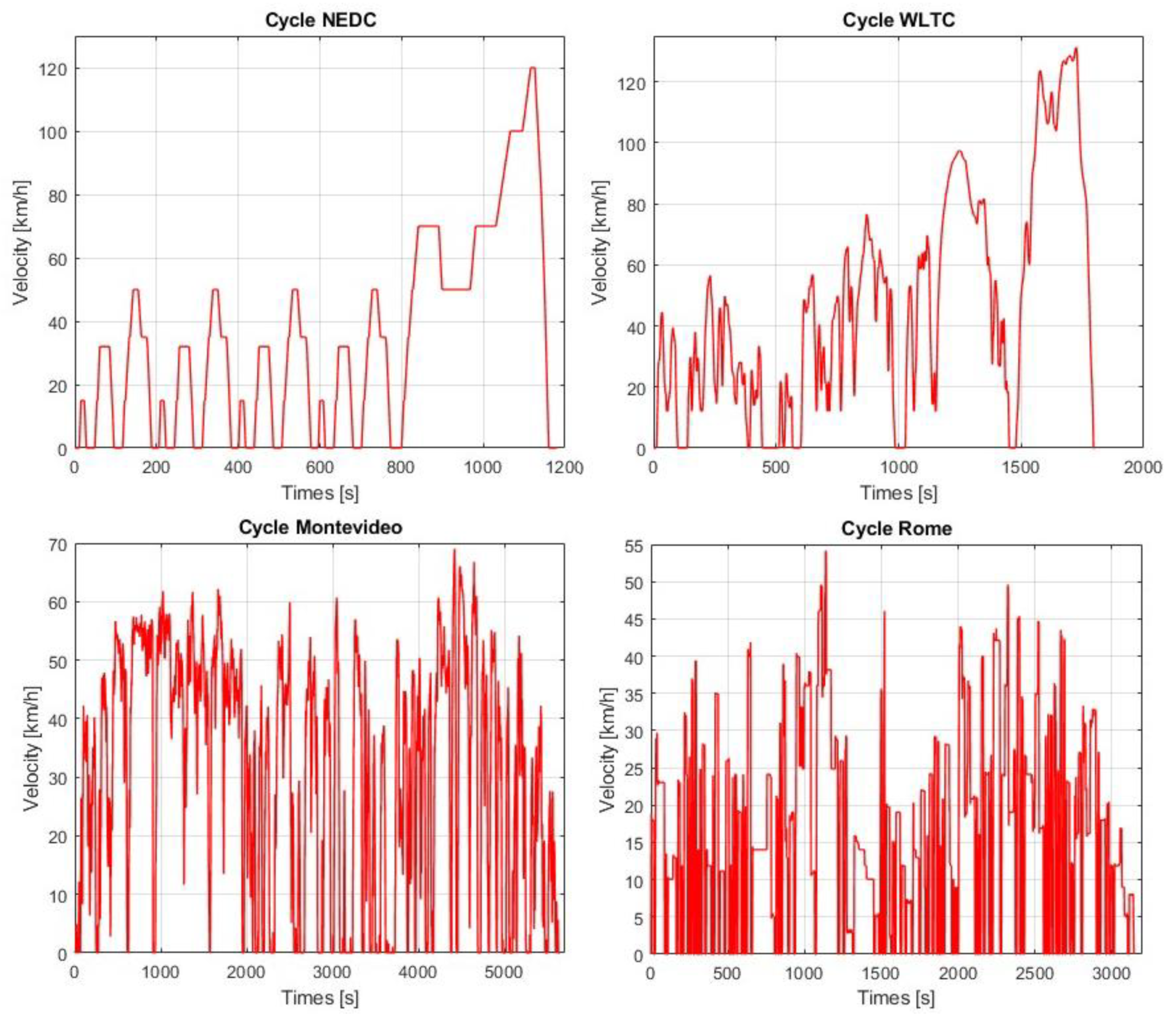
The vehicle is tested under different real driving cycles as well as under maximum acceleration test. The tested driving cycles encompass the NEDC, NEDC City, NEDC Highway, WLTC, which is a specific cycle measured in Montevideo and Rome. Figure 5 shows the driving cycles profiles and Table 3 the main statistics parameters. These cycles are designed to emulate typical driving conditions across diverse settings, including urban/downtown, urban/out of town, and highway environments. Their purpose is to simulate the vehicle’s behavior in varied scenarios, offering valuable insights for design improvements and evaluations. While four of these cycles adhere to standardized protocols, facilitating the comparison of simulation results with those of other vehicles evaluated under similar conditions, non-standardized cycles provide a more nuanced analysis of the vehicle’s performance in diverse scenarios. This extends to both gasoline and hydrogen-powered vehicles as well as hydrogen hybrid vehicles.
The Maximum Acceleration Test, or Full Load Acceleration, entails the driver delivering a signal of maximum load to the engine with gear shifts occurring at specified RPMs to rapidly achieve the highest possible speed. Executed in a straight line, this test aims to ascertain the vehicle’s maximum acceleration. Within this cycle, the evaluation centers on observing how the vehicle’s speed changes over time and the time required to reach specific speeds, such as 100 km/h, among others. It is crucial to clarify that most of the test’s demands are placed on the engine and the entire power transmission system, collectively defining the test outcome. This meticulous examination ensures a comprehensive understanding of the vehicle’s performance under high-stress conditions, contributing valuable insights to its overall assessment.

3. Results and Discussion

The findings from the computational models are scrutinized with a focus on analyzing three pivotal factors that hold utmost significance in the realm of vehicles. A comprehensive assessment of performance is conducted through an acceleration test, which is followed by an analysis of energy consumption. Furthermore, due regard is given to the consideration of the vehicle’s autonomy, acknowledging its critical role in the overall evaluation. This tripartite analysis aims to provide a holistic understanding of the computational model’s outcomes and their implications on the broader context of vehicle dynamics.
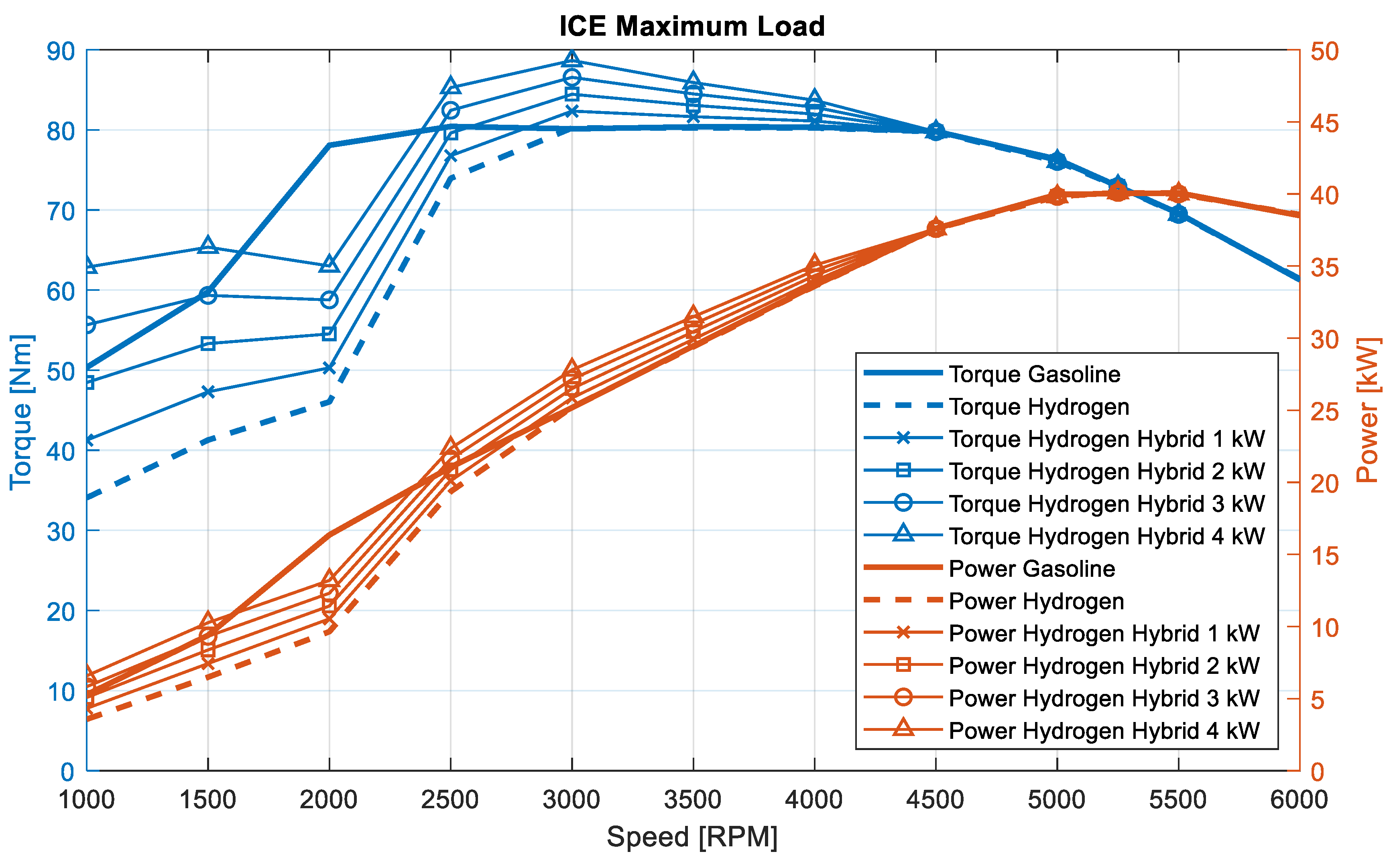
A previously mentioned factor critical in design and analysis is the “lack of power” due to lower volumetric efficiency specific for hydrogen. To demonstrate this effect and how different hybridizations compensate for it, Figure 6 shows the power and torque curves of the various configurations, which are all on the engine’s output axis. The addition of 3 and 4 kW EM allows the hydrogen engine to achieve the power of the gasoline engine already at 1500 RPM while improving the power at high engine speeds. To have a better analysis of the electric motor impact, the next section analyzes the performance under full acceleration with all engine versions.

3.1. Performance

A comprehensive test was conducted primarily focusing on FLA of the engine to evaluate the vehicle’s performance. In this assessment, the driver controller was programmed to accelerate until reaching maximum power. As mentioned previously, the hydrogen engine exhibits a notable lack of power between 1000 and 3000 RPM. Consequently, a meticulous design approach was applied to both the EM, the belt, and the control strategy to effectively address this power limitation. Furthermore, to underscore the magnitude of this limitation in the results, two FLA tests were executed, with shift points set at 2500 RPM and 5500 RPM, which were both initiated with a launch speed of 1400 RPM. The outcomes of these tests are presented in Figure 7. A notable difference between purely gasoline and purely hydrogen versions can be observed as well as the difference between shift points. These contrasts are important as they clearly show the variation in performance between models with and without hybridization under different conditions. For the shift point set at 2500 RPM, the effect of each model is clearly observed. The hybrid versions of 1 and 2 kW fail to reach the top speed of the gasoline model even after an extensive amount of time. On the other hand, it is evident that in the hybrid versions, the 3 kW and 4 kW EMs effectively counteract this power deficiency. It is worth noting that even after 60 s of the FLA test, both hybrid models manage to surpass the gasoline model in speed. With the shift point at 5500 RPM, the impact of power lack is notably diminished. This is attributed to the shifts being executed away from the power deficiency zone, as vividly depicted in the image. It is noteworthy that the 3 and 4 kW models manage to equal or surpass the gasoline model almost all of the time, while at the beginning, the 1 and 2 kW models still remain slightly below the gasoline model.
Thanks to the analysis of the FLA cycle, the 1 and 2 kW models are ruled out, as they fail to meet the main objective of mitigating power loss. It is worth mentioning that models with power greater than 4 kW were not used because at maximum power usage, the demanded C-rate on the battery would be very high and would lead to significant degradation. The hydrogen vehicle, after passing this maximum acceleration test, will be able to maintain a speed of 135 km/h, which is the same as the gasoline version.
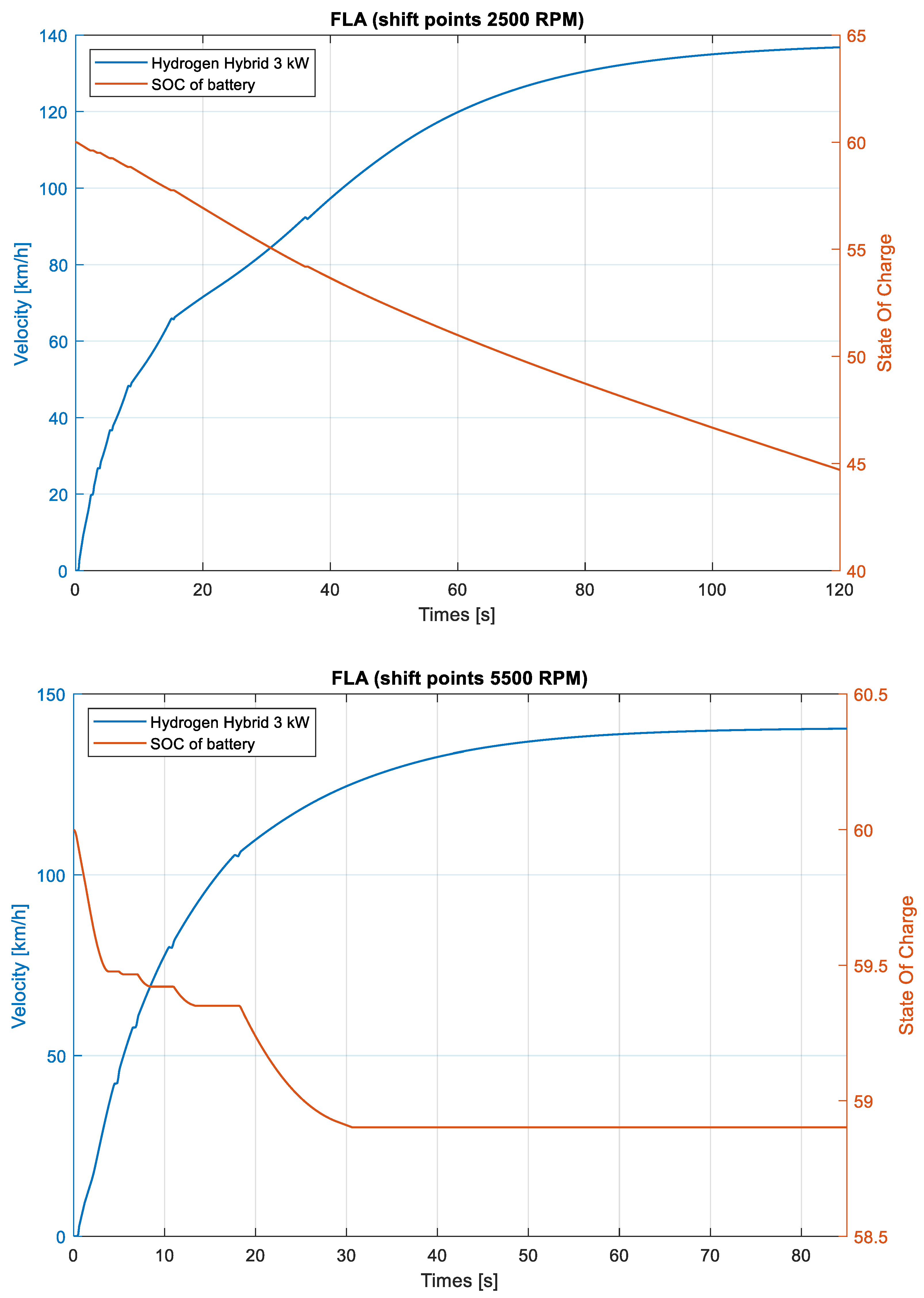
Figure 8 shows the state of charge for the hybrid configuration equipped with the 3 kW EM. It highlights an essential aspect of battery management, i.e., a “worst case” scenario. More to the point, this situation covers the maximum power that the driver would require within the shortest time. It entails acceleration from standstill to top speed and is the regime that is the hardest on the battery. A crucial result is the depth of discharge at the end of such an event. For the 5500 RPM shift point, there is no issue given that once the engine reaches such high rotational velocity, the additional power from the EM is no longer necessary, i.e., the boosting level achieved by the turbocharger unit ensures the required power output. For the 2500 RPM shift point on the other hand, it is quite evident that there is significant battery discharge, which is of around 15% start-to-end of the acceleration episode. This figure is nonetheless fully compatible with extensive battery life and can be clearly handled without the need for SoC values below 20% or above 80%, which are well known for significantly affecting useful life [33]. The proposed configuration would also be able to handle the acceleration event with a different strategy for controlling the SoC. More to the point, if the strategy would be aimed at keeping the SoC around 50% (e.g., in this way recovering energy during coasting would be improved while still being able to provide enough energy for vigorous acceleration), the figure of approximately 15% discharge would be enough for accelerating from standstill to top speed. If a second acceleration event would be required, this would still comply with the aforementioned requirement of avoiding SoC values below 20%.

3.2. Real Driving Cycles Evaluation

To comprehensively assess the performance of the models within the context of real driving cycles and to facilitate a comparative analysis of the achieved consumptions and ranges, simulations were conducted for a spectrum of driving scenarios. This diversified set of driving cycles serves to offer a robust evaluation framework, enabling a nuanced examination of the models’ capabilities across varied and realistic driving conditions.
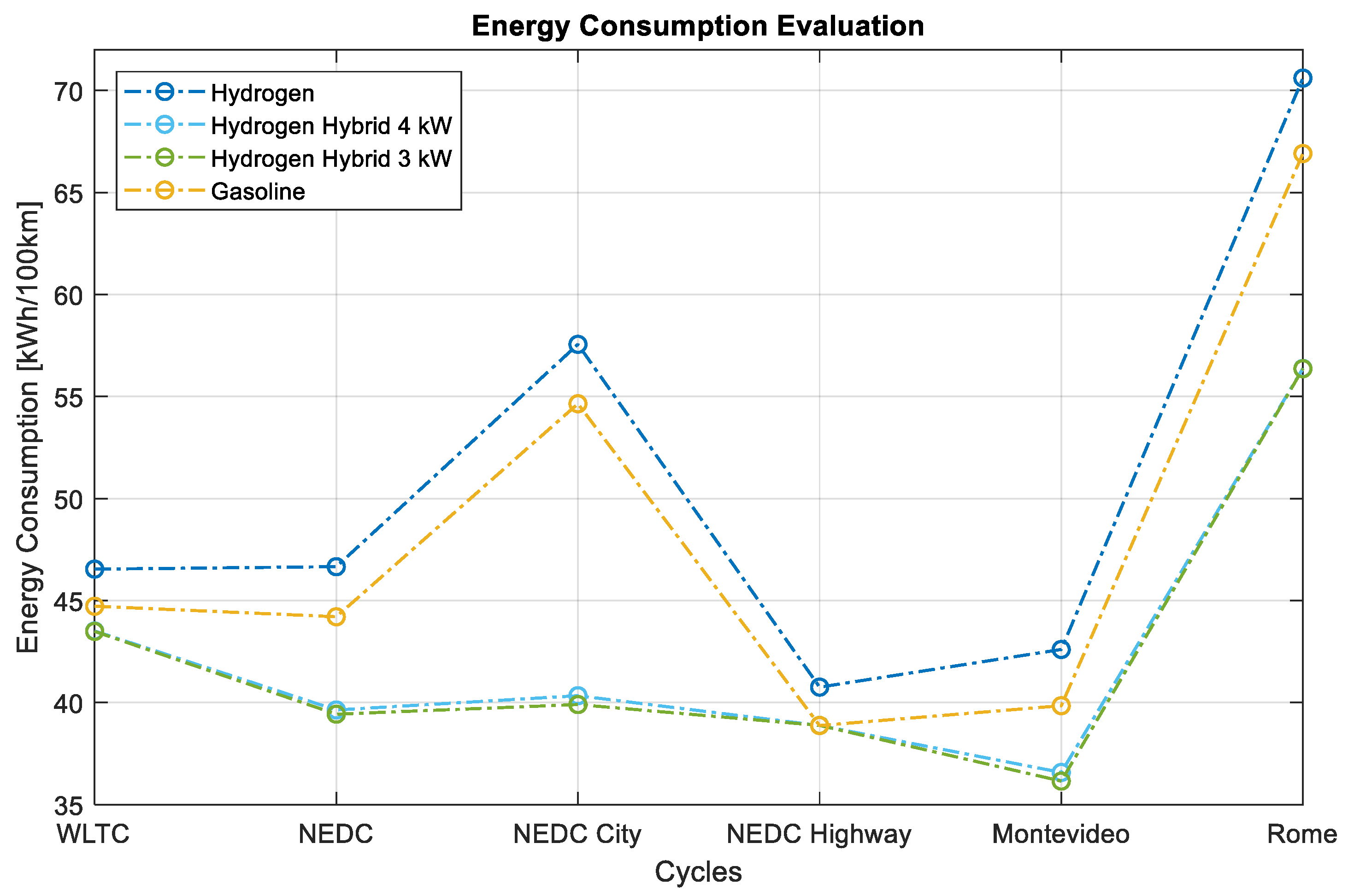
To conduct a thorough fuel economy equivalent comparison within diverse driving cycles, the energy consumption (kWh/100 km) of distinct models in each cycle was meticulously evaluated. This approach facilitated a comprehensive performance assessment and allowed for the comparison between different models, elucidating discernible improvements. These models underwent simulation across various driving cycles, and for the calculations, the energy corresponding to the battery was considered.
The results of this comparative analysis for the four configurations models are graphically presented in Figure 9. It is important to note that for these calculations, a LHV of 43.5 MJ/kg for gasoline and 120.0 MJ/kg for hydrogen was employed. This meticulous consideration of energy values enhances the accuracy of the comparative analysis, providing valuable insights into the performance differentials across the specified driving cycles.
In all vehicle configurations, range stands out as a critical determinant, influencing the frequency of refueling stops. As widely acknowledged, this range is contingent on several variables, encompassing factors such as vehicle load, driving cycles, and the utilization of vehicle accessories, among others. Taking into account these multifaceted aspects, the range attained by both pure hydrogen and hybrid models was systematically simulated across diverse driving cycles.
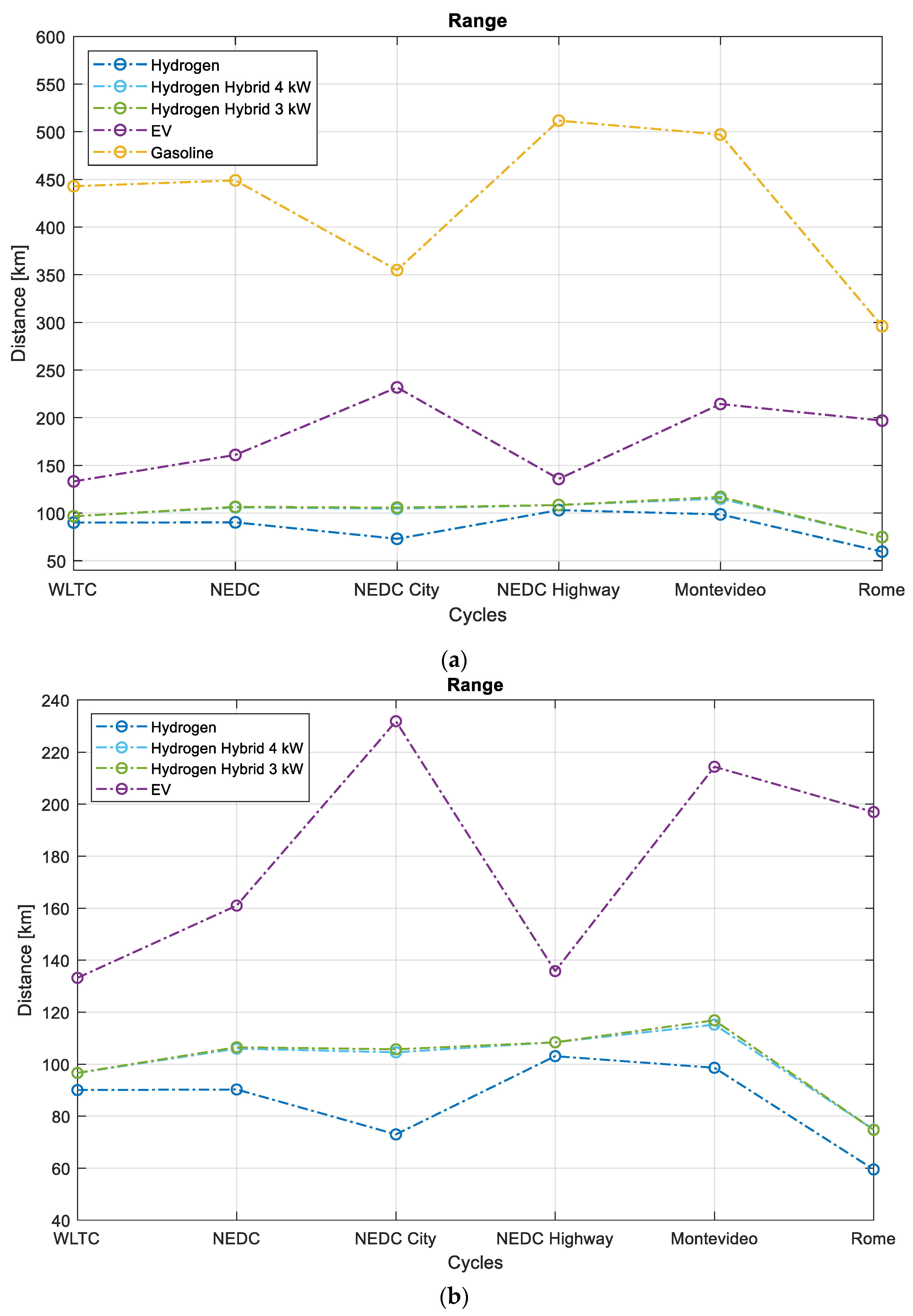
To replicate the fuel tank in the model, a 30 L hydrogen tank at 700 bar [25] was employed, factoring in a density of 42 g/L. The models were programmed to regulate their cumulative fuel consumption. Once the tank’s predefined limit was reached, the simulation was halted, yielding the distance covered by the vehicle in each driving cycle. Figure 10 shows the range achievable with different configurations across various driving cycles; these include hydrogen hybrids, pure hydrogen, electric and gasoline vehicles. It should be noted that the autonomy of gasoline models is considerably greater than hydrogen models, usually exceeding 400 km. For a better visualization of the autonomy of the hydrogen and electric models, the bottom of Figure 10b is added, where the range of the gasoline model is removed. However, compared to the electric version of 17.7 kWh lithium-ion battery and 133 km under WLTC, the hydrogen version shows similar behavior [34]. This deliberate exclusion serves to focus the analysis on the specificities of hydrogen models and their respective ranges. It is important to note that the refueling time for the 30 L hydrogen tank in a vehicle is approximately 5 min. Meanwhile, in the electric vehicle, the maximum charging time is 1 h with a 22 kW charger at 400 V, and with a home charger, it can take up to 9 h, all for charges from 0 to 100% [32,35].

3.3. Battery Behavior under Different Driving Cycles

Due to engineering considerations in both vehicle design and production, it is important to consider the vehicle’s battery [36,37,38,39]. Therefore, an analysis of the current thought the battery connections is performed: specifically, the C-rate (Current (A)/Battery Capacity (Ah)) to which it is subjected is conducted, as it is of great importance for its lifespan. The 3 kW and 4 kW hybrid hydrogen models and the electric model are analyzed. It is important to understand that in this work, the battery in the HEV and the EV have the same chemical composition for a fair comparison.
The strategy for electrical energy consumption plays a crucial role in both the vehicle’s performance and the longevity of the battery. Therefore, the control strategies employed for the EM are of utmost importance [35].
The battery management strategy for the hybrid model consists of three modules: regeneration, traction, and motor torque control:
  • Regeneration Module: This module calculates the torque needed for electromagnetic (EM) braking to generate energy for the battery. It uses the brake pedal position to determine proportional torque, which is limited by the motor’s maximum regeneration torque to prevent battery damage. If speed exceeds 5 km/h, regenerative braking is utilized.
  • Traction Module: Designed to assist the Internal Combustion Engine (ICE) at low rotational speeds, it activates the EM to support the ICE when the required torque approaches its full load. EM’s maximum torque is restricted by battery discharge C-rate (<10 1/h) and EM limitations.
  • Control Module: Receives signals from previous modules and dictates EM actions based on vehicle state. It operates in four states determined by battery charge level:
    • Normal operation mode (charge > 20%): EM operates in regenerative mode and traction as per driver’s needs.
    • Battery charging mode (charge < 20%): EM exclusively regenerates.
    • Charging mode (charge < 60%): Maintains charging until battery reaches 60%.
    • Normal operation mode (charge ≥ 60%): EM functions in both regenerative and traction modes.
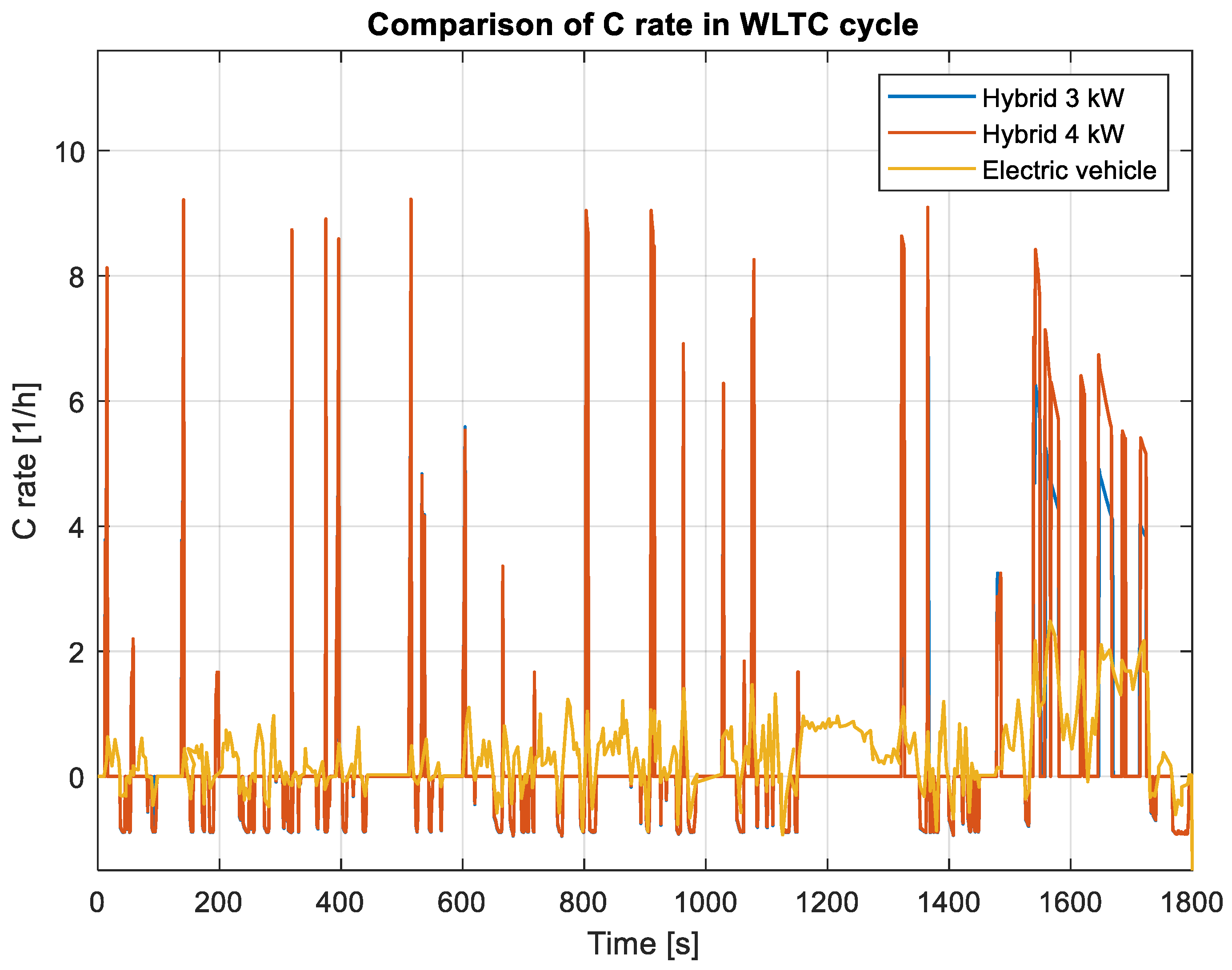
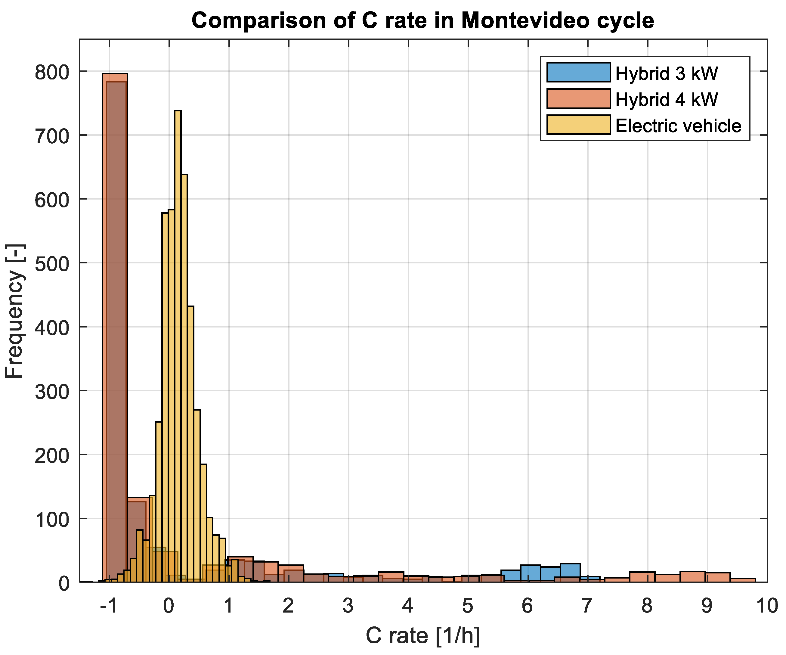
After conducting the driving cycles, the AVL Cruise M allows to obtain the current and C-rate profiles. The result can be observed in Figure 11 for the homologation WLTC and Figure 12 for an urban cycle (Montevideo). As expected, it is observed that the C-rates of the hybrid models are considerably higher than those of the electric model. Therefore, it is possible to obtain higher degradation in the batteries of the hybrid models. However, as shown in Figure 12, these high C-rates do not occur as frequently as lower ones, so the degradation must be investigated in depth. Also, Figure 11 shows that the battery use in the hybrid is lower in time than that of the EV. The traction periods occur because in general, the HEV is off or not at high power, while the EV is always under use. It should be noted that this study did not address the degradation generated in the battery, but it could be the subject of investigation in future projects.
When comparing the WLTC cycle in Figure 11 to that in Figure 5, it can be observed that most of the C-rate peaks occur at the beginning of the vehicle’s movement or during acceleration periods. This result was expected, considering the electric motor control system.

4. Conclusions

The outcomes of the simulations underscore that the hybridization of the vehicle converted to hydrogen not only addresses challenges inherent in the conversion process but also brings about enhancements in specific facets of the vehicle. The key findings are summarized as follows:
  • Performance: The hybridization of the hydrogen model demonstrates a remarkable achievement, nearly equating or surpassing the performance when compared to the gasoline model. The electric motor with a maximum power of 3 kW boosting the H2 ICE is the best compromise between performance and cost. The MHEV H2 concept equips a 1 kWh battery. This allows less lithium-ion materials than the EV version (18 kWh).
  • Energy Consumption: The implemented modifications yield a more efficient vehicle, manifesting in lower energy consumption across nearly all evaluated driving cycles. The average improvement (five cycles tested) is around 11% with respect to the gasoline version and 19% with respect to the conventional powertrain. The latter is the best suited option only for the highway cycles.
  • Vehicle Range: Hybridization introduces notable improvements in the range of the configurations and particularly in urban cycles. Even if as an absolute value, range is lower for H2-fueled versions, it is comparable to the BEV, and when considering the refilling time, it is an extremely attractive choice compared to the difficulties correlated with extensive charging times. Consequently, hybridization stands out as a viable solution for the decarbonization of the light vehicle fleet.
  • Battery management: One key aspect of the hybrid configurations is that despite the small size of the 48V battery pack that results in numerous charging–discharging cycles, the lifetime should be fully compatible with that expected for the entire vehicle. The full throttle acceleration simulations can be ensured at the end of an event starting from standstill and running up to top speed with an SoC above 35% if starting from 50% initial charge. This can be further mitigated by changing the gear shift strategy, further enhancing management margins. These suggests that even in worst-case scenarios, “normal” battery management can ensure extensive lifetime, even if cycling is much heavier compared to the BEV version.
As an overall conclusion, the study shows that retrofitting a gasoline passenger car for H2 fueling and rendering it hybrid electric results in a vehicle with fully compatible performance but with reduced carbon emissions as well as a range comparable to the BEV version. Incorporating an efficient catalytic exhaust system into the conversion further enables the achievement of vehicles with practically zero NOx emissions. This multifaceted approach not only enhances environmental sustainability but also underscores the potential of hybrid hydrogen vehicles in contributing to the broader goal of fleet decarbonization. In addition to the data presented in the conclusion, suggestions for future efforts will concentrate on the calibration of hydrogen engines within a controlled test bed environment. This process will involve optimizing combustion parameters and conducting extensive emissions measurements to enhance the performance and efficiency of hydrogen-powered internal combustion engines. Moreover, further investigation will be dedicated to exploring battery improvement strategies particularly aimed at mitigating degradation resulting from the high cycles experienced in hybrid applications. This research will delve into understanding the underlying mechanisms of battery degradation and explore innovative approaches to prolong battery life and enhance overall performance in mild hybrid vehicles.

Author Contributions

Conceptualization, S.M.-B., A.I. and P.C.-R.; methodology, S.M.-B., A.I. and S.M.; validation, S.B. and S.M.-B.; formal analysis, S.B. and S.M.; data curation, S.M.-B. and A.I.; writing—original draft preparation, S.B. and S.M.-B.; writing—review and editing, A.I. and S.M.; visualization, S.M.-B. and A.I.; supervision, S.M. and P.C.-R. All authors have read and agreed to the published version of the manuscript.

Funding

The authors from STEMS-CNR acknowledge the funding received within the SAYH2 PoC project financed by the European Union—NextGenerationEU (National Sustainable Mobility Center CN00000023, Italian Ministry of University and Research Decree n. 1033—17/06/2022, Spoke 12) and the funding received within the STRIVE FOE2022 project, WP2 Refurbishment of light duty vehicles (original title in Italian).

Data Availability Statement

The raw data supporting the conclusions of this article will be made available by the authors on request.

Acknowledgments

The help of Antonio Rossi is gratefully acknowledged.

Conflicts of Interest

The authors declare no conflicts of interest.

Abbreviations

ICEinternal combustion engine
EMelectric motor
FLAfull load acceleration
OEMoriginal equipment manufacturer
MHEVmild hybrid electric vehicle
LHVlower heating value
NEDCNew European Driving Cycle
WLTCWorldwide Harmonized Light Vehicles Test Procedure
RPMRevolution Per Minute
BTEbrake thermal efficiency
GHGgreenhouse gases
FCEVfuel cell electric vehicles
FCfuel cell
H2hydrogen
SMRsteam reforming
DOEUnited States Department of Energy
EVelectric vehicle
COcarbon monoxide
CO2carbon dioxide
Ssulfur
NH3ammonia
NOxnitrogen oxidizer
H2ICEhydrogen-fueled Internal Combustion Engines
EUEuropean Union
SOIStart of Injection
EGRExhaust Gas Recirculation
BMEPBrake Mean Effective Pressure
PFIPort Fuel Injected
DIDirect Injection
CCVcycle-to-cycle variability
e-fuelsgreen fuels
SOCstate of charge
HCNGhydrogen-enriched compressed natural gas

References

  1. Molina, S.; Novella, R.; Gomez-Soriano, J.; Olcina-Girona, M. Impact of medium-pressure direct injection in a spark-ignition engine fueled by hydrogen. Fuel 2024, 360, 130618. [Google Scholar] [CrossRef]
  2. De Colvenaer, B.; Castel, C. The fuel cells and hydrogen joint undertaking (FCH JU) in Europe. Int. J. Low-Carbon Technol. 2012, 7, 5–9. [Google Scholar] [CrossRef]
  3. Novas, N.; Garcia Salvador, R.M.; Portillo, F.; Robalo, I.; Alcayde, A.; Fernández-Ros, M.; Gázquez, J.A. Global Perspectives on and Research Challenges for Electric Vehicles. Vehicles 2022, 4, 1246–1276. [Google Scholar] [CrossRef]
  4. Usmanov, U.; Ruzimov, S.; Tonoli, A.; Mukhitdinov, A. Modeling, Simulation and Control Strategy Optimization of Fuel Cell Hybrid Electric Vehicle. Vehicles 2023, 5, 464–481. [Google Scholar] [CrossRef]
  5. Chojnowski, J.; Dziubak, T. Multi-Criteria Analysis of Semi-Trucks with Conventional and Eco-Drives on the EU Market. Energies 2024, 17, 1018. [Google Scholar] [CrossRef]
  6. Düzgün, M.T.; Dorscheidt, F.; Krysmon, S.; Bailly, P.; Lee, S.Y.; Dönitz, C.; Pischinger, S. Virtual Multi-Criterial Calibration of Operating Strategies for Hybrid-Electric Powertrains. Vehicles 2023, 5, 1367–1383. [Google Scholar] [CrossRef]
  7. Martinez-Boggio, S.; Di Blasio, D.; Fletcher, T.; Burke, R.; García, A.; Monsalve-Serrano, J. Optimization of the air loop system in a hydrogen fuel cell for vehicle application. Energy Convers. Manag. 2022, 283, 116911. [Google Scholar] [CrossRef]
  8. Ruffini, E.; Wei, M. Future costs of fuel cell electric vehicles in California using a learning rate approach. Energy 2018, 150, 329–341. [Google Scholar] [CrossRef]
  9. Papadias, D.D.; Ahmed, S.; Kumar, R.; Joseck, F. Hydrogen quality for fuel cell vehicles—A modeling study of the sensitivity of impurity content in hydrogen to the process variables in the SMR-PSA pathway. Int. J. Hydrogen Energy 2009, 34, 6021–6035. [Google Scholar] [CrossRef]
  10. Murugan, A.; Brown, A.S. Review of purity analysis methods for performing quality assurance of fuel cell hydrogen. Int. J. Hydrogen Energy 2015, 40, 4219–4233. [Google Scholar] [CrossRef]
  11. Zhou, P.; Gao, S.; Wang, B.; Wang, Y.; Li, C.; Wang, Y.; Sun, B. Influence of hydrogen fuel cell temperature safety on bus driving characteristics stack heating mode. Int. J. Hydrogen Energy 2022, 48, 11541–11554. [Google Scholar] [CrossRef]
  12. Ahmadi, P.; Khoshnevisan, A. Dynamic simulation and lifecycle assessment of hydrogen fuel cell electric vehicles considering various hydrogen production methods. Int. J. Hydrogen Energy 2022, 47, 26758–26769. [Google Scholar] [CrossRef]
  13. Evangelisti, S.; Tagliaferri, C.; Brett, D.J.L.; Lettieri, P. Life cycle assessment of a polymer electrolyte membrane fuel cell system for passenger vehicles. J. Clean. Prod. 2017, 142, 4339–4355. [Google Scholar] [CrossRef]
  14. Molina, S.; Novella, R.; Pla, B.; Lopez-Juarez, M. Optimization and sizing of a fuel cell range extender vehicle for passenger car applications in driving cycle conditions. Appl. Energy 2020, 285, 116469. [Google Scholar] [CrossRef]
  15. Nakagawa, K.; Yamane, K.; Ohira, T. Potential of large output power, high thermal efficiency, near-zero NOx emission, supercharged, lean-burn, hydrogen-fuelled, direct injection engines. Energy Procedia 2012, 29, 455–462. [Google Scholar] [CrossRef]
  16. Naganuma, K.; Honda, T.; Yamane, K.; Takagi, Y.; Kawamura, A.; Yanai, T.; Sato, Y. Efficiency emissions-optimized operating strategy of a high-pressure direct injection hydrogen engine for heavy-duty trucks. SAE Int. J. Engines 2010, 2, 132–140. [Google Scholar] [CrossRef]
  17. Engels, M.; Jakoby, M.; Fahrbach, T.; Andert, J. Hybridisation Concept of Light Vehicles Utilising an Electrified Planetary Gear Set. Vehicles 2023, 5, 1622–1633. [Google Scholar] [CrossRef]
  18. Bao, L.; Sun, B.; Luo, Q. Optimal control strategy of the turbocharged direct-injection hydrogen engine to achieve near-zero emissions with large power and high brake thermal efficiency. Fuel 2022, 325, 124913. [Google Scholar] [CrossRef]
  19. Verhelst, S. Recent progress in the use of hydrogen as a fuel for internal combustion engines. Int. J. Hydrogen Energy 2014, 39, 1071–1085. [Google Scholar] [CrossRef]
  20. White, C.M.M.; Steeper, R.R.R.; Lutz, A.E.E. The hydrogen-fueled internal combustion engine: A technical review. Int. J. Hydrogen Energy 2006, 31, 1292–1305. [Google Scholar] [CrossRef]
  21. Kyjovský, Š.; Vávra, J.; Bortel, I.; Toman, R. Drive cycle simulation of light duty mild hybrid vehicles powered by hydrogen engine. Int. J. Hydrogen Energy 2023, 48, 16885–16896. [Google Scholar] [CrossRef]
  22. Martinez, S.; Merola, S.S.; Irimescu, A. Flame Front and Burned Gas Characteristics for Different Split Injection Ratios and Phasing in an Optical GDI Engine. Appl. Sci. 2019, 9, 449. [Google Scholar] [CrossRef]
  23. Verhelst, S.; Sierens, R.; Verstraeten, S. A Critical Review of Experimental Research on Hydrogen Fueled SI Engines; SAE Technical Paper 2006-01-0430; SAE: Warrendale, PA, USA, 2006. [Google Scholar] [CrossRef]
  24. Huyskens, P.; Van Oost, S.; Goemaere, P.; Bertels KPecqueur, M. The Technical Implementation of a Retrofit Hydrogen PFI System on a Passenger Car; SAE Technical Paper 2011-01-2004; SAE: Warrendale, PA, USA, 2011. [Google Scholar] [CrossRef]
  25. Irimescu, A.; Vaglieco, B.; Merola, S.; Zollo, V.; De Marinism, R. Conversion of a Small Size Passenger Car to Hydrogen Fueling: Focus on Rated Power and Injection Phasing Effects; SAE Technical Paper 2022-24-0031; SAE: Warrendale, PA, USA, 2022. [Google Scholar] [CrossRef]
  26. Ha, J.; Park, J.; Kwon, O.B.; Lim, I.G.; Yun, J.H.; Keel, S.I.; Park, H.Y.; Kim, T.H. Flame extinction in interacting CO-air and syngas-air premixed flames. J. Mech. Sci. Technol. 2015, 29, 419–428. [Google Scholar] [CrossRef]
  27. Molina, S.; Ruiz, S.; Gomez-Soriano, J.; Olcina-Girona, M. Impact of hydrogen substitution for stable lean operation on spark ignition engines fueled by compressed natural gas. Results Eng. 2022, 17, 100799. [Google Scholar] [CrossRef]
  28. Szamrej, G.; Karczewski, M. Exploring Hydrogen-Enriched Fuels and the Promise of HCNG in Industrial Dual-Fuel Engines. Energies 2024, 17, 1525. [Google Scholar] [CrossRef]
  29. Martinez, S.; Merola, S.S.; Curto, P.; Vaglieco, B.M.; Irimescu, A. Conversion of a Small Size Passenger Car to Hydrogen Fueling: Focus on Vehicle Dynamics and ECU Remapping Requirements; SAE Technical Paper 2023-24-0065; SAE: Warrendale, PA, USA, 2023. [Google Scholar]
  30. Demuynck, J.; De Paepe, M.; Huisseune, H.; Sierens, R.; Vancoillie, J.; Verhelst, S. On the applicability of empirical heat transfer models for hydrogen combustion engines. Int. J. Hydrogen Energy 2011, 36, 975–984. [Google Scholar] [CrossRef]
  31. Nagappa, M.; Hebbur Rameshbabu, A. Comparison of Predictive Gasoline Combustion Models Using GT-Power. Master Thesis, Chalmers University of Technology, Gothenburg, Sweden, 2016. [Google Scholar]
  32. Smart EQ Fortwo Coupe 60 kW Tech Specs. Available online: https://autocatalogarchive.com/wp-content/uploads/2021/09/Smart-ForTwo-EQ-ForFour-EQ-2021-UK.pdf (accessed on 13 November 2023).
  33. Smart-City-Coupe-55. Available online: www.ultimatespecs.com (accessed on 2 December 2023).
  34. Mallon, K.R.; Assadian, F.; Fu, B. Analysis of On-Board Photovoltaics for a Battery Electric Bus and Their Impact on Battery Lifespan. Energies 2017, 10, 943. [Google Scholar] [CrossRef]
  35. Pramanik, S.; Anwar, S. Predictive Optimal Control of Mild Hybrid Trucks. Vehicles 2022, 4, 1344–1364. [Google Scholar] [CrossRef]
  36. Smart EQ Fortwo Coupe (2020–2023) Price and Specifications—EV Database. Available online: https://ev-database.org/car/1230/Smart-EQ-fortwo-coupe (accessed on 15 November 2023).
  37. Jaguemont, J.; Van Mierlo, J. A comprehensive review of future thermal management systems for battery-electrified vehicles. J. Energy Storage 2020, 31, 101551. [Google Scholar] [CrossRef]
  38. Pinto, C.; Barreras, J.V.; de Castro, R.; Araújo, R.E.; Schaltz, E. Study on the combined influence of battery models and sizing strategy for hybrid and battery-based electric vehicles. Energy 2017, 137, 272–284. [Google Scholar] [CrossRef]
  39. Atalay, S.; Sheikh, M.; Mariani, A.; Merla, Y.; Bower, E.; Widanage, W.D. Theory of battery ageing in a lithium-ion battery: Capacity fade, nonlinear ageing and lifetime prediction. J. Power Sources 2020, 478, 229026. [Google Scholar] [CrossRef]
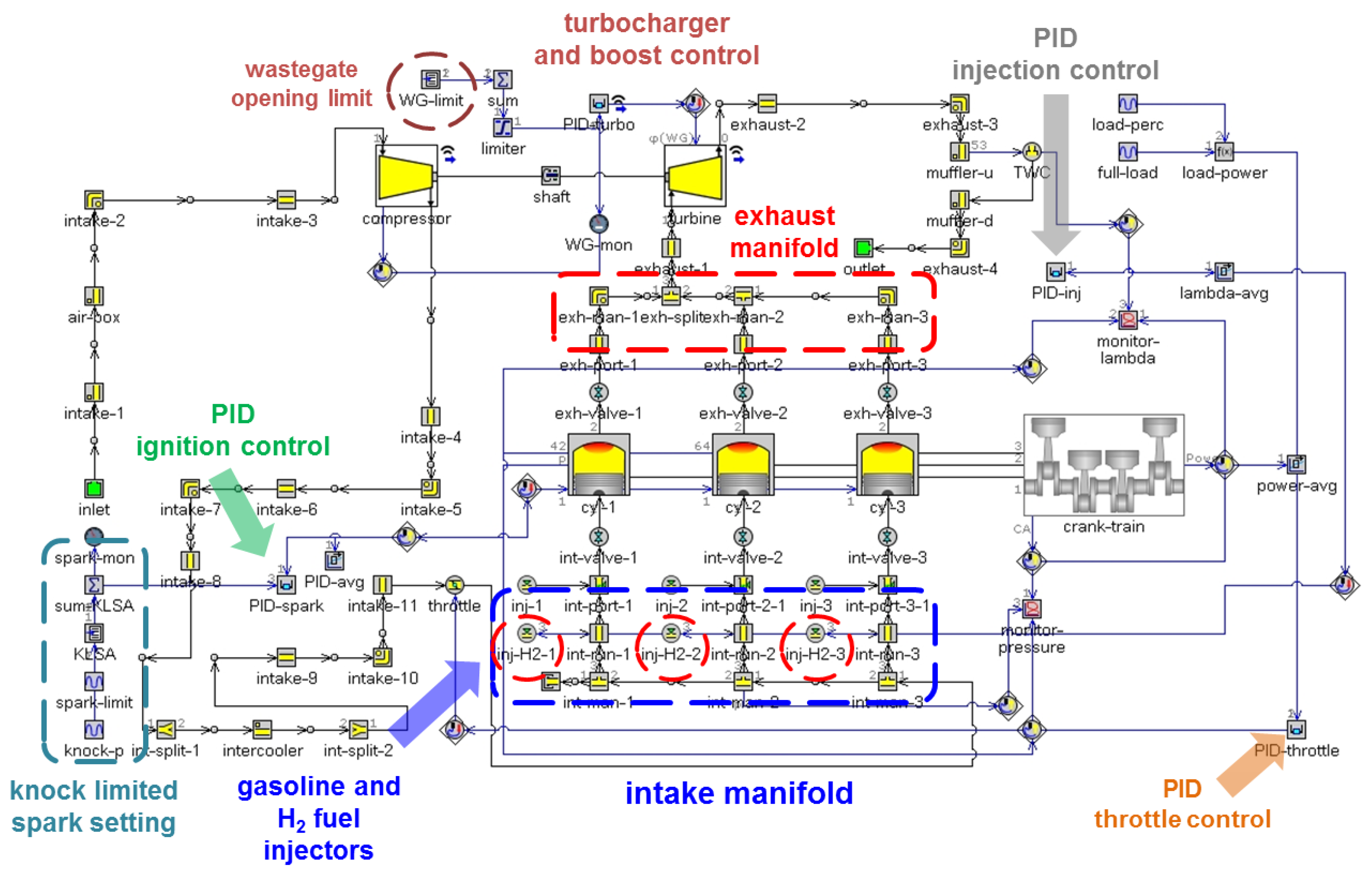
Figure 1. Overview of the 0D/1D simulation model in its gasoline/H2 PFI configuration with selected components highlighted.
Machines 12 00355 g001
Figure 2. Brake thermal efficiency results for gasoline (a) and H2 (b) against different engine speeds and load obtained from 1D engine simulations.
Machines 12 00355 g002
Figure 3. Vehicle model validation based on fuel consumption data.
Machines 12 00355 g003
Figure 4. MHEV concept layout in the simulation graphic user interface of AVL Cruise M.
Machines 12 00355 g004
Figure 5. Driving cycles used for the simulations.
Machines 12 00355 g005
Figure 6. Torque and power curves at different engine output shaft speeds [RPM].
Machines 12 00355 g006
Figure 7. Full load acceleration cycles with launch speed at 1400 RPM and shift points set at 2500 RPM and 5500 RPM.
Machines 12 00355 g007
Figure 8. Full load acceleration cycles for the 3 kW hybrid version with launch speed at 1400 RPM and shift points in 2500 RPM (top) and 5500 RPM (bottom).
Machines 12 00355 g008
Figure 9. Energy consumptions for the different configurations.
Machines 12 00355 g009
Figure 10. Maximum range under different driving cycles (a) and zoom-in image of the zero-carbon configurations (b).
Machines 12 00355 g010
Figure 11. The C-rate as a function of time in the battery of the hybrid vehicle models equipped with 3 kW, 4 kW motors and the electric vehicle version. These data correspond to the driving cycle in WLTC.
Machines 12 00355 g011
Figure 12. C-rate recorded in the battery of the hybrid vehicle models equipped with 3 kW, 4 kW motors and the electric vehicle version. These data correspond to the driving cycle in Montevideo.
Machines 12 00355 g012
Table 1. Engine specifications.
ItemValue
Displacement599 cm3
Number of cylinders3
Bore × stroke63.5 × 63 mm
Compression ratio9.5:1
Number of valves2 per cylinder
Rated power40 kW @5250 RPM
Air fillingturbocharger
Fuel systemport fuel injection at 3.5 bar for gasoline and
5 bar for hydrogen
Ignition systeminductive discharge, 2 spark plugs per cylinder
Table 2. Vehicle specifications in the three versions.
Vehicle Type [-]Non-HybridMHEVEV
Vehiclesmall size passenger car 2-seater
Vehicle Drag Coefficient [-]0.37
Frontal Area [m2]1.99
Tires Size [mm/%/inch]175/55 R15
Rolling resistance factor [%]1.1
Top speed [km/h]135130
Base vehicle Mass [kg]7207651095
Passenger and Cargo Mass [kg]75
Differential ratio [-]4.21:19.9221:1
Primary Energy Source [-]GasolineHydrogenLithium-Ion Battery
Second Energy Source [-]NoneLithium-Ion BatteryNone
Fuel tank [L]2230None
Lithium-Ion Battery Size [kWh]None0.9817.6
Lithium-Ion Battery mass [kg]None5.4180
Lithium-Ion Battery Volume [L]None4.0100
Electric machine Power [kW]NoneTBD60
Table 3. Average statistical parameters for the different driving routes.
Country/CityRoute TypeTotal Distance [km]Time [min]Vapos95 [m2/s3]
NEDCMixed11.0319.677.4
Uruguay/MontevideoUrban—Avenue47.49418.3
Italy/RomeUrban—City13.552.423.2
Disclaimer/Publisher’s Note: The statements, opinions and data contained in all publications are solely those of the individual author(s) and contributor(s) and not of MDPI and/or the editor(s). MDPI and/or the editor(s) disclaim responsibility for any injury to people or property resulting from any ideas, methods, instructions or products referred to in the content.