Article

State of Charge Estimation for Lithium-Ion Battery Based on Fractional-Order Kreisselmeier-Type Adaptive Observer

by
Tomoki Murakami
1 and
Hiromitsu Ohmori
2,*
1
Graduate School of Science and Technology, Keio University, Yokohama 223-8522, Japan
2
Department of System Design Engineering, Keio University, Yokohama 223-8522, Japan
*
Author to whom correspondence should be addressed.
Machines 2024, 12(10), 738; https://doi.org/10.3390/machines12100738
Submission received: 15 July 2024 / Revised: 8 October 2024 / Accepted: 17 October 2024 / Published: 20 October 2024
(This article belongs to the Special Issue Advanced Engine Energy Saving Technology)

Abstract

:
For the safe and efficient use of lithium-ion batteries, the state of charge (SOC) is a particularly important state variable. In this paper, we propose a method for the online estimation of SOC and model parameters based on a fractional-order equivalent circuit model. Firstly, we constructed a fractional-order battery model that includes pseudo-capacitance and determined the values of the circuit elements offline using the least squares method from actual input–output data based on the driving profile of an automobile. Compared to the integer-order battery model, we confirmed that the proposed fractional-order battery model has higher accuracy. Secondly, we constructed a fractional-order Kreisselmeier-type adaptive observer as an observer that performs state estimation and parameter adjustment simultaneously. Applying the general adaptive law to the battery model results in a redundant design with many adjustable parameters, so we proposed an adaptive law that reduces the number of adjustable parameters without compromising the stability of the observer. The effectiveness of the proposed method was verified through numerical simulations. As a result, the high estimation accuracy and convergence of the proposed adaptive law were confirmed.

1. Introduction

With air pollution, global warming, and the energy crisis becoming important and pressing issues, electric vehicles (EVs) have been drawing increasing attention [1]. Lithium-ion batteries, with their advantages of high energy density, long lifespan, and low cost, are widely used as a power source for EVs [2]. To ensure the safe and efficient use of lithium-ion batteries, battery management systems (BMSs) monitor the state variables of the batteries [3]. These state variables include temperature, state of health (SOH) and state of power (SOP). Among the monitored states, state of charge (SOC) is particularly important. SOC is defined as the ratio of the remaining capacity to the maximum capacity of the battery. Accurate SOC measurement enables the prevention of overcharging and overdischarging of the battery, as well as the prediction of the driving range, so SOC is necessary for battery control [4]. However, SOC cannot be measured directly and must be estimated using observable values such as battery current and voltage.
In previous studies, various methods for estimating the SOC of batteries have been proposed [5,6], which can be classified into model-free and model-based approaches. The Coulomb counting method, categorized as a model-free approach, is the simplest method with low computational cost. However, due to its lack of a feedback structure, errors from the battery current sensor and initial SOC estimation continue to accumulate. The open-circuit voltage (OCV) method estimates SOC from measured OCV values using the OCV-SOC relationship. This method is effective when accurate OCV values can be obtained. However, it has been reported that stabilizing the OCV in lithium-ion batteries requires prolonged rest periods, and the OCV-SOC relationship varies with temperature and degradation [7,8,9]. In data-driven SOC estimation methods, neural networks [10] are often employed. However, these methods require large amounts of data and the estimation accuracy depends on the training dataset. Additionally, low extrapolation capability has been pointed out [11].
Model-based methods, on the other hand, combine a model describing battery behavior with an observer to estimate SOC. Compared to model-free methods, they offer advantages such as higher reliability and better control performance. There are two primary types of battery models: electrochemical models and equivalent circuit models (ECMs). Electrochemical models are based on diffusion phenomena inside the battery and can accurately replicate battery responses, but their high computational burden is a challenge [12]. ECMs, on the other hand, consist of basic circuit elements and are simpler, which makes them widely used in research. It is common to combine ECMs with Kalman Filters (KFs) for SOC estimation. For instance, Ref. [13] linearizes the model and uses a KF for SOC estimation. For models with nonlinearities, Ref. [14] uses an Extended Kalman Filter (EKF), while Ref. [15] uses the Unscented Kalman Filter (UKF) for SOC estimation.
It has been reported that the characteristics of batteries fluctuate due to degradation and other factors [16]. Against this background, many methods have incorporated adaptability into filtering algorithms. For example, Ref. [17] simultaneously performs SOC estimation and parameter adjustment of the equivalent circuit model using the Unscented Kalman Filter.
In recent years, there have been numerous reports on using fractional calculus-based models for batteries. Ref. [18] plots the frequency response of the battery impedance on the complex plane and shows that constant phase elements with fractional order are needed to reproduce its characteristic shape. Ref. [19] utilizes a fractional-order adaptive observer to estimate the internal state of batteries. Ref. [20] performs SOC estimation using a fractional-order EKF, achieving improved estimation accuracy compared to integer-order EKF. Ref. [17] conducts SOC estimation using fractional-order EKF and parameter adjustment using fractional-order UKF. However, KF-based methods require the prior knowledge of noise variance as a design parameter, which is a trial-and-error process. Therefore, in practical use, the design parameters need to be adjusted each time the magnitude of the noise changes. In the case of a Luenberger-type observer, if estimation has been performed on data containing a certain amount of noise, the estimation accuracy tends to improve with the data containing a smaller amount of noise without changing the design parameters. In contrast, the KF-based method may lose estimation accuracy in similar situations. In EVs, where a variety of operating environments are expected, it is difficult to know the characteristics of the noise, and this is an issue with the KF-based estimation method.
The contributions of this study are as follows. First, a fractional-order model is used as the battery model, which can accurately reproduce the battery’s response. Second, SOC estimation is conducted by a fractional-order Kreisselmeier-type adaptive observer that is adaptive to deal with variations in battery characteristics. This has advantages over KF-based methods in that it does not require a priori noise information and does not require changes in design parameters when noise characteristics change. For the method of constructing the observer, refer to [19].
The rest of this paper is organized as follows. Section 2 describes the fundamentals of fractional calculus and a simulation method. Section 3 describes a battery model and a parameter identification result. A fractional-order Kreisselmeier-type adaptive observer and a proposed adaptive law are described in Section 4. The numerical simulation results of the proposed method under the US06 and FUDS tests are discussed in Section 5. Finally, Section 6 concludes this article.

2. Fractional Calculus

In this section, we briefly outline Caputo’s definition, which is widely used among various fractional calculus definitions [21,22]. Additionally, we introduce approximate simulation methods for fractional-order systems.

2.1. Definition of Fractional Calculus

For a function f ( t ) , the q-th order Caputo fractional derivative is defined as follows:
D t q 0 [ f ( t ) ] = 0 t ( t τ ) n q 1 Γ ( n q ) f ( n ) ( τ ) d τ
where n 1 < q < n . In this definition, the n-th derivative of f ( τ ) is first computed, followed by integrating it n q times with respect to τ to obtain the q-th order derivative. An important property is that this fractional derivative satisfies the additivity of orders:
D t q 2 0 D t q 1 0 [ f ( t ) ] = D t q 1 + q 2 0 [ f ( t ) ]
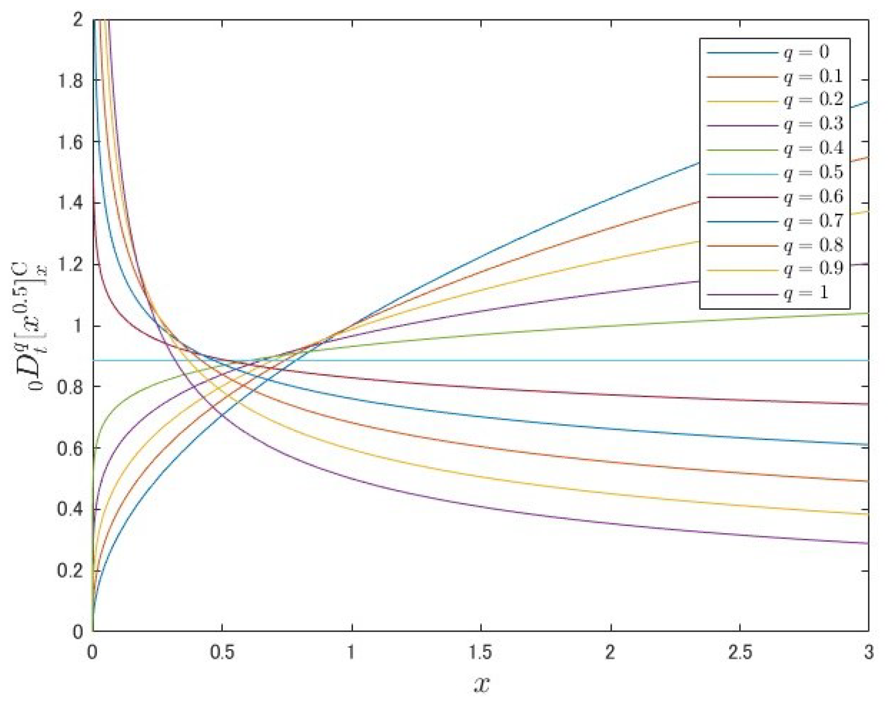
The results of calculating the fractional derivative of the power function according to Caputo’s definition are shown in Figure 1.
From Figure 1, we can see that the fractional derivative has properties on the graph that are intermediate between the original function and the first-order derivative.

2.2. Simulation Methods for Fractional-Order Systems

Consider a q-th-order linear fractional-order system as shown below.
D q x ( t ) = A x ( t ) + b u ( t ) , x ( 0 ) = x 0
y ( t ) = c x ( t )
When conducting simulations of this system, operations involving real power transfer functions s q are necessary. However, fractional calculus requires the computation of convolution integrals from the initial time, which is difficult to achieve accurately considering the computational cost. Therefore, in this study, we approximate fractional integrals using a method called the Manabe approach [23].
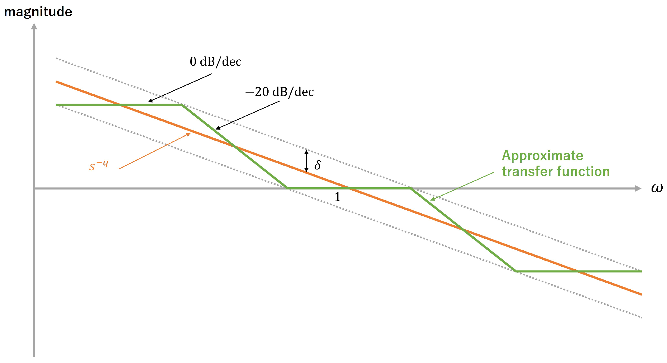
The Bode diagram of the frequency response of the fractional-order integral s q shows that the amplitude response is a straight line with a slope of 20 q [ dB / dec ] and the phase response is constant at 90 q [ deg ] regardless of frequency. In the Manabe approach, this Bode diagram is approximated by an integer-order transfer function. A schematic diagram is shown in Figure 2.
In the Manabe approach, the approximate transfer function is expressed by the following equation:
s q = i = 1 j s + a i s + b i × i = 1 k 1 + b i s 1 + a i s , Ω low < ω < Ω high
where
0 < q < 1
δ = 20 log 10 α
β = α 2 q ( 1 q )
a 1 = α 1 q
a i + 1 = a i β
b i = a i α 2 1 q
Ω low = a j + 1
Ω high = 1 a k + 1
[ Ω low , Ω high ] denotes the frequency range to be approximated. For the design parameters, k determines the approximate range on the high frequency side, and j determines the approximate range on the low frequency side. Additionally, δ determines the approximation accuracy.

3. Battery Model

In this section, we will explain the fractional-order equivalent circuit model and the integer-order equivalent circuit model of the battery. Additionally, using actual input–output data from the battery, we will perform offline optimization of the circuit component values and compare the accuracy between the integer-order model and the fractional-order model.

3.1. Battery Data

The battery datasets used in this paper are from open-source datasets provided by the Center for Advanced Life Cycle Engineering (CALCE), a research group at the University of Maryland, and was used at an ambient temperature of 30 °C [24]. The battery is an 18650 type, manufactured by A123 systems, a company headquartered in Novi, MI, USA. The specifications of the battery are shown in the Table 1.
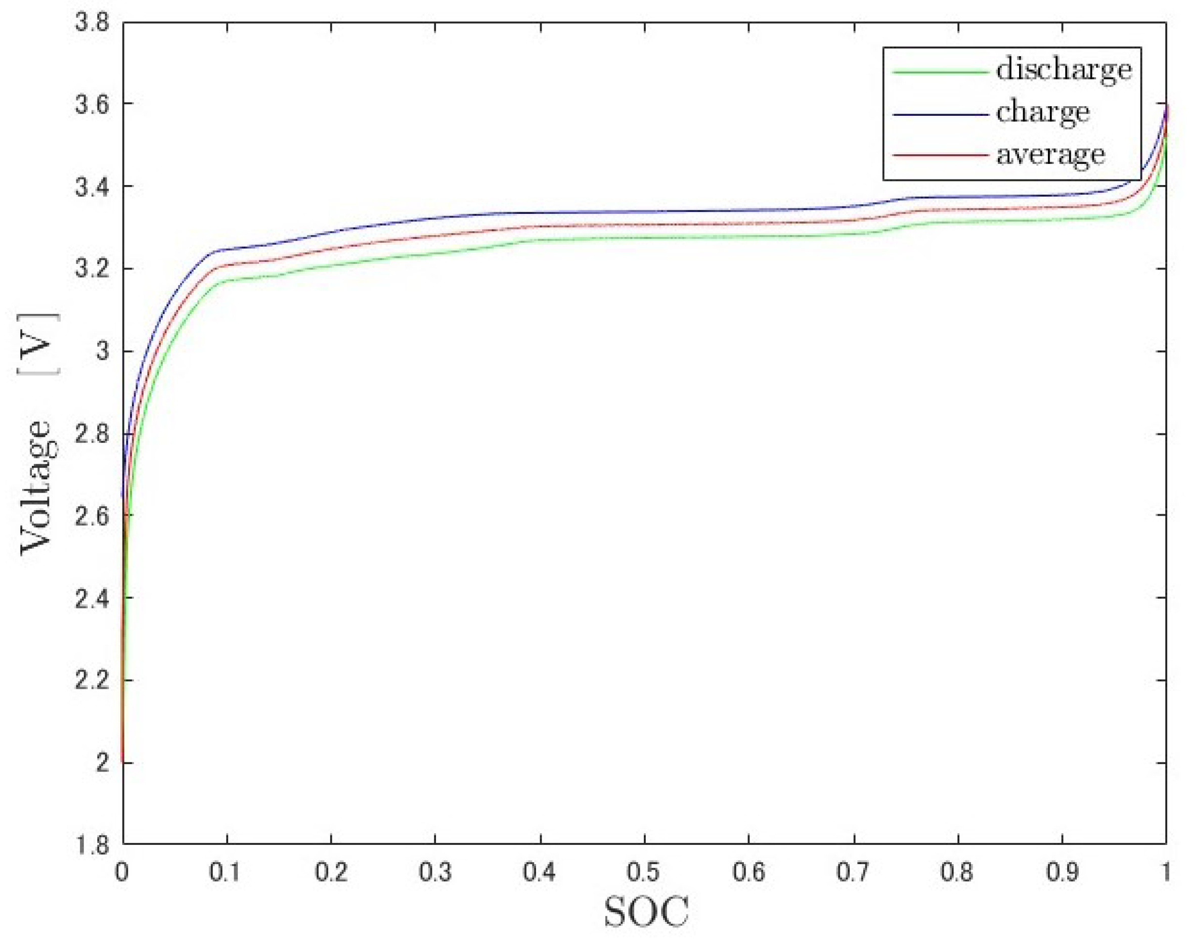
Using the low current test included in the dataset, we obtain the OCV-SOC curve that represents the relationship between the OCV and SOC of the battery. In this test, the battery is first charged to the upper limit of terminal voltage, 3.6 V (SOC: 1), and then left for one hour to stabilize. Following this, the battery is discharged at a current rate of 0.05 C until the terminal voltage reaches the lower limit of 2.0 V (SOC: 0), with the OCV measured during this period. Subsequently, the battery is left for another hour before being recharged at a current rate of 0.05 C until the terminal voltage again reaches the upper limit of 3.6 V . SOC during discharge and charge is calculated using the Coulomb counting method. The use of a small current rate of 0.05 C is intended to minimize the effects of battery overpotential. Additionally, the rest periods between charging and discharging are included to ensure the battery is in an equilibrium state before measurements are taken. The OCV-SOC curves obtained from these measurements during discharge and charging are shown in Figure 3.
From Figure 3, it can be seen that the OCV has hysteresis with respect to the SOC. To minimize this effect, the OCV-SOC curve in this study is the average of the charging and discharging values.

3.2. Fractional-Order Battery Model

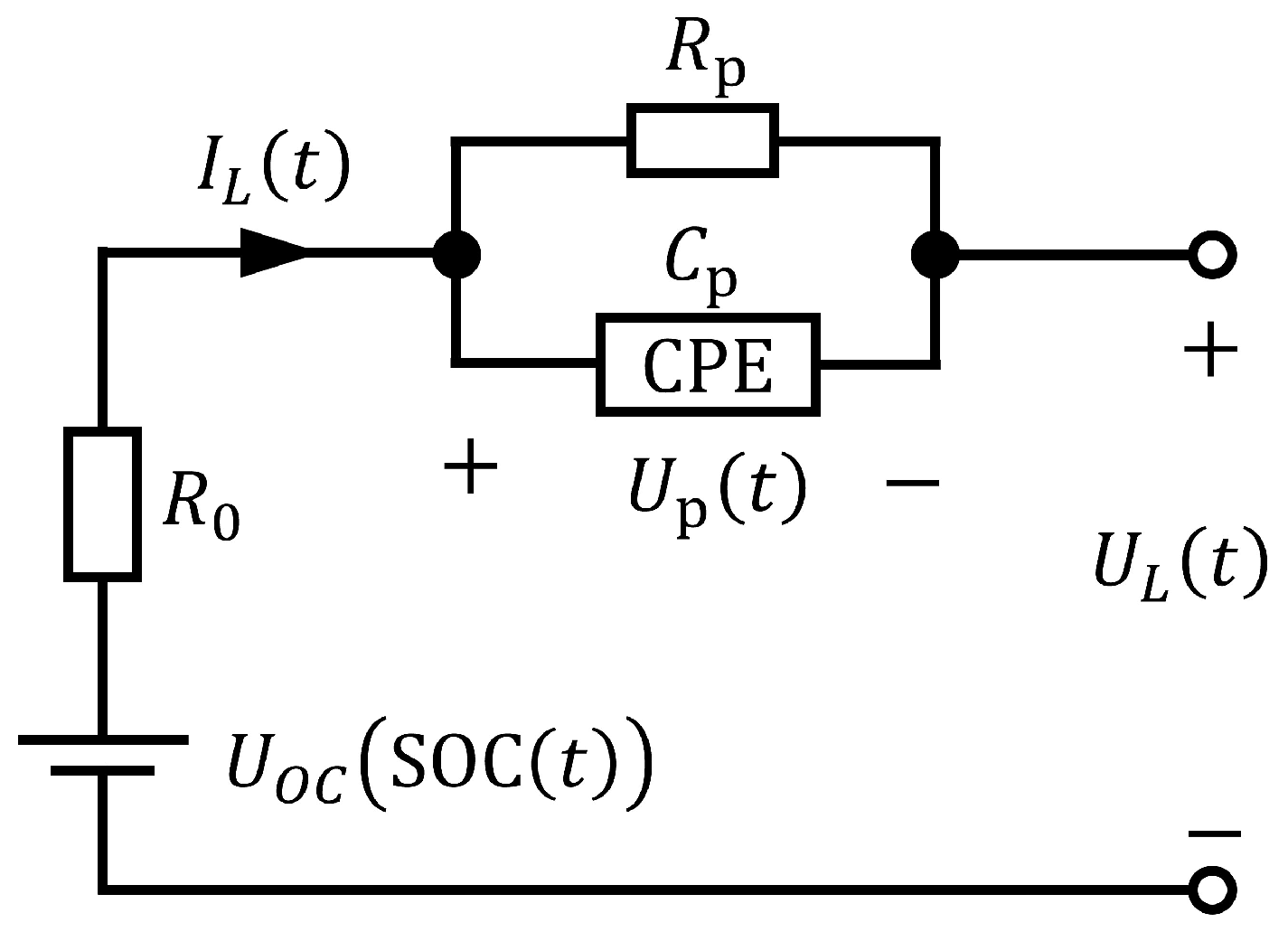
The fractional-order equivalent circuit diagram used in this study is shown in Figure 4.
In Figure 4, U OC represents the OCV, I L the battery current, U L the terminal voltage, and U p the voltage on the parallel part. CPE is the constant phase element, and the impedance Z CPE in the Laplace domain is expressed by the following equation.
Z CPE = 1 C p s α , 0 < α < 1
Assuming α = 0.5 , the following equation is obtained for the battery current I L ( t ) .
I L ( t ) = U p ( t ) R p + C p D 0.5 U p ( t )
This transforms into the following equation.
D 0.5 U p ( t ) = 1 C p R p U p ( t ) + 1 C p I L ( t )
The following relationship holds for the terminal voltage U L ( t ) .
U L ( t ) = U OC ( SOC ( t ) ) U p ( t ) R 0 I L ( t )
The dynamics of SOC can be expressed as follows.
d d t SOC ( t ) = η C n I L ( t )
C n represents the nominal capacity, which for the battery used in this study is C n = 1100 mAh , as described in Table 1. η represents the charge–discharge efficiency and, in this study, η = 0.98 . Combining these equations results in the following state-space representation.
x ( t ) = U p ( t ) SOC ( t ) D 0.5 SOC ( t )
D 0.5 x ( t ) = 1 R p C p 0 0 0 0 1 0 0 0 x ( t ) + 1 C p 0 η C n I L ( t )
U L ( t ) = U OC ( SOC ( t ) ) 1 0 0 x ( t ) R 0 I L ( t )
Thus, the battery can be modeled as a fractional-order system with input I L ( t ) and output U L ( t ) .

3.3. Integer-Order Battery Model

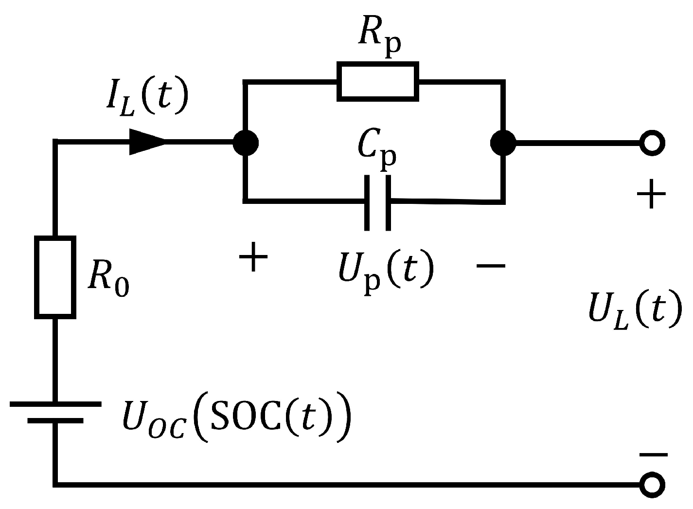
An integer-order equivalent circuit diagram used as a comparison for fractional-order equivalent circuits is shown in Figure 5.
The CPE in the fractional-order equivalent circuit of Figure 4 is replaced by the capacitance C p in the integer-order equivalent circuit of Figure 5. In this integer-order equivalent circuit, the following relationship is obtained for the battery current I L ( t ) .
I L ( t ) = U p ( t ) R p + C p d d t U p ( t )
This transforms into the following equation.
d d t U p ( t ) = 1 C p R p U p ( t ) + 1 C p I L ( t )
The same relationship holds for the terminal voltage U L ( t ) and SOC as in the fractional-order equivalent circuit. From these equations, the following state-space representation is obtained.
x ( t ) = U p ( t ) SOC ( t )
d d t x ( t ) = 1 R p C p 0 0 0 x ( t ) + 1 C p η C n I L ( t )
U L ( t ) = U OC ( SOC ( t ) ) 1 0 x ( t ) R 0 I L ( t )
Thus, the battery can be modeled as an integer-order system with input I L ( t ) and output U L ( t ) .

3.4. Offline Optimization

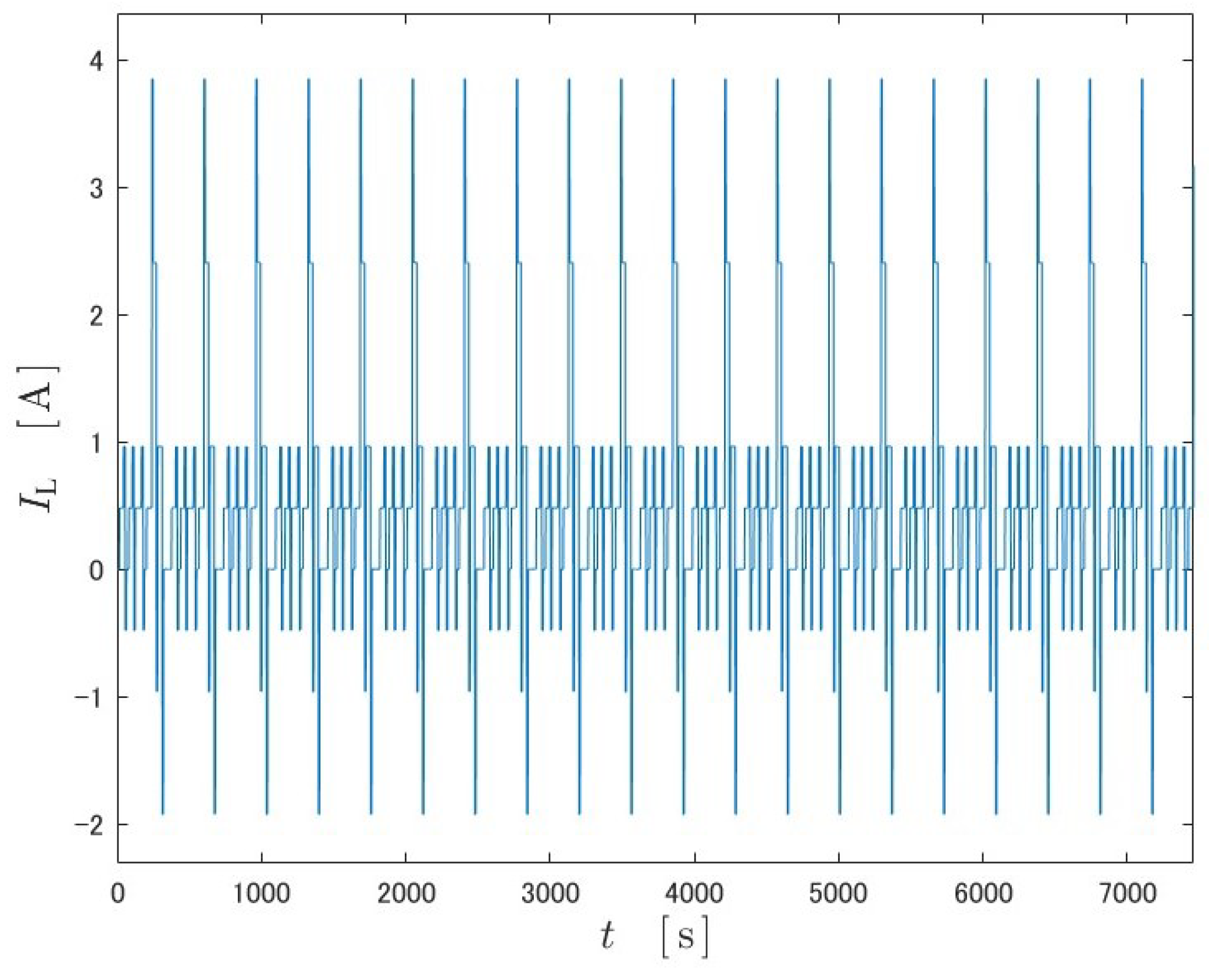
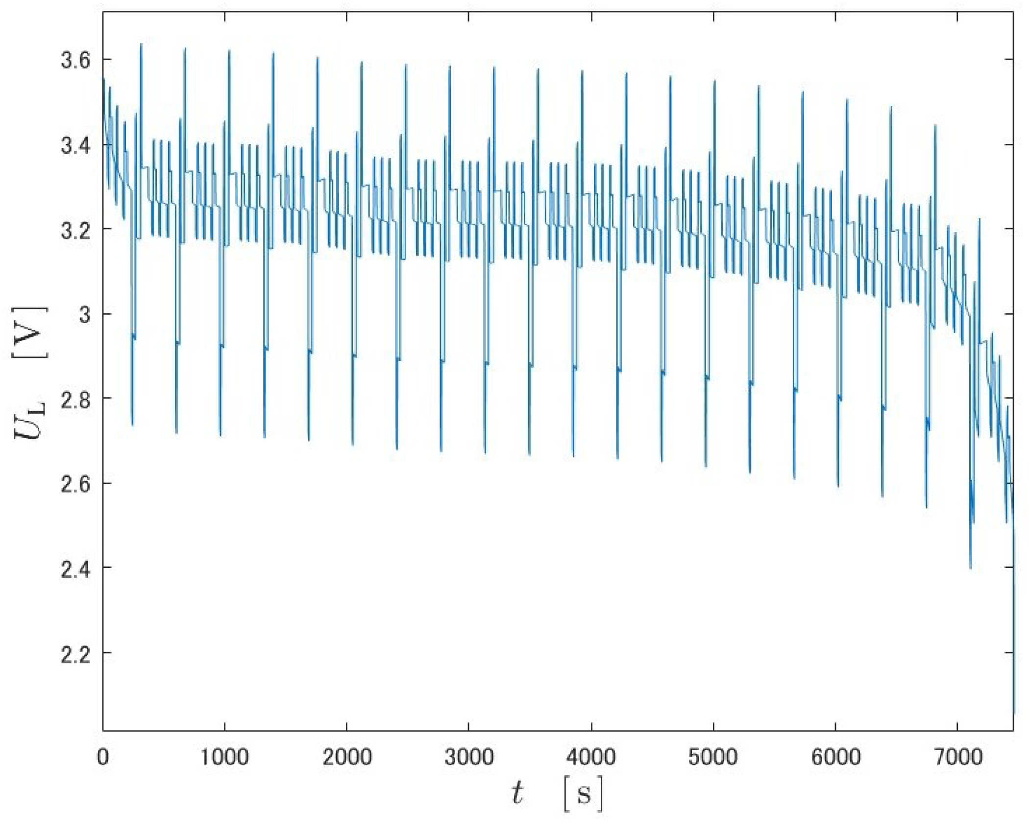
In the state-space representation of the fractional-order and integer-order models, the values of the circuit parameters R p , C p , R 0 must be identified using battery input–output data. The time series of battery current I L ( t ) and terminal voltage U L ( t ) used as battery input–output data in this study are shown in Figure 6 and Figure 7. This current time series is determined based on the profile DST, with positive values of current indicating discharge and negative values indicating charging.
Under the condition that the initial value of SOC can be obtained and the exact value of the current is available, the battery can calculate the time series of SOC using Equation (18). In this offline estimation, the initial value of SOC is available, and the time series of the current can be obtained as shown in Figure 6, so the time series of SOC can be calculated.
Using these data, the model parameters R p , C p , R 0 that minimize the output estimation error for fractional order and integer order, respectively, were obtained using the least squares method. The data were taken from within the range where the OCV can be approximated linearly, and the interval used for the data was 2000 t 5000 s . The root mean square error (RMSE) values for each circuit element and output estimate are shown in the Table 2.
From Table 2, the RMSE of a fractional order model is 6.3 mV , while that of the integer order is 9.7 mV . This indicates that the fractional-order equivalent circuit shown in Figure 4 reproduces the input–output of the battery more accurately than the integer-order equivalent circuit shown in Figure 5.

4. Observer

The Kreisselmeier-type observer is an adaptive observer proposed by Kreisselmeier [25]. The fractional-order Kreisselmeier-type adaptive observer, which extends this to fractional orders, is described in this section with reference to [19].

4.1. Fractional-Order Kreisselmeier-Type Adaptive Observer

The following single-input, single-output fractional-order plant is the observed object.
D 1 / m x ( t ) = A x ( t ) + b u ( t ) , x ( 0 ) = x 0
y ( t ) = c x ( t )
A = α 1 1 0 0 α 2 0 1 0 0 α n 1 0 0 1 α n 0 0
b = β 1 β 2 β n 1 β n
c = 1 0 0 0
where u ( t ) , y ( t ) are the plant input and output, respectively, and α i , β i are the unknown parameters.
Now, the following assumptions are made for this fractional-order plant.
  • Plant is asymptotically stable;
  • Observable;
  • Highest degree n / m is known.
Under these assumptions, we construct a fractional-order adaptive observer that estimates the state x ( t ) and identifies the unknown parameters α i , β i online from the input–output signals u ( t ) , y ( t ) .
The state equation in Equation (27) can be rewritten as follows:
D 1 / m x ( t ) = F x ( t ) + ( α f ) y ( t ) + β u ( t )
where
F = g f K
f = f 1 f 2 f n
α = α 1 α 2 α n
β = β 1 β 2 β n
g = 1 0 0
K = 0 I n 2 0 0
Suppose R y ( t ) , R u ( t ) , ζ y ( t ) , ζ u ( t ) are given by the following formula.
D 1 / m R y ( t ) = F R y ( t ) + I n y ( t ) , R y ( 0 ) = 0
D 1 / m R u ( t ) = F R u ( t ) + I n u ( t ) , R u ( 0 ) = 0
ζ y ( t ) = R y ( t ) c
ζ u ( t ) = R u ( t ) c
In this case, Equations (28) and (32) can be rewritten as follows:
x ( t ) = j = 0 F j t 1 m j Γ ( 1 m j + 1 ) x 0 + R y ( t ) ( α f ) + R u ( t ) β
y ( t ) = c j = 0 F j t 1 m j Γ ( 1 m j + 1 ) x 0 + ζ y ( t ) ( α f ) + ζ u ( t ) β
Furthermore, the following equations hold for ζ y ( t ) , ζ u ( t ) .
D 1 / m ζ y ( t ) = F ζ y ( t ) + c y ( t )
D 1 / m ζ u ( t ) = F ζ u ( t ) + c u ( t )
Moreover, R y ( t ) , R u ( t ) can also be expressed as follows.
R y ( t ) = c c F c F n 1 1 ζ y ( t ) ζ y F ( t ) ζ y ( t ) F n 1
R u ( t ) = c c F c F n 1 1 ζ u ( t ) ζ u ( t ) F ζ u ( t ) F n 1
When Equations (39) and (40) are used to obtain R y ( t ) , R u ( t ) , it is necessary to calculate the fractional calculus for each n 2 element. On the other hand, if we use Equations (47) and (48), the number of calculations of fractional calculus can be reduced to n times, which is required to obtain ζ y ( t ) , ζ u ( t ) .
Using these expressions, Equations (43) and (44) can be expressed as follows:
x ( t ) = R ( t ) θ + z ( t )
y ( t ) = ζ ( t ) θ + c z ( t )
θ = ( α f ) β
R ( t ) = R y ( t ) R u ( t )
ζ ( t ) = ζ y ( t ) ζ u ( t )
z ( t ) = j = 0 F j t 1 m j Γ ( 1 m j + 1 ) x 0
The state estimate x ^ ( t ) and output estimate y ^ ( t ) are designed using the initial estimate x ^ 0 and parameter estimate θ ^ ( t ) as follows:
x ^ ( t ) = R ( t ) θ ^ ( t ) + z ^ ( t )
y ^ ( t ) = ζ ( t ) θ ^ ( t ) + c z ^ ( t )
z ^ ( t ) = j = 0 F j t 1 m j Γ ( 1 m j + 1 ) x ^ 0
θ ^ ( t ) = ( α ^ ( t ) f ) β ^ ( t )
where α ^ ( t ) , β ^ ( t ) denote the estimated value of α , β at each time.
The error ϵ ( t ) between the plant output y ( t ) and its estimated value y ^ ( t ) can be expressed as follows:
ϵ ( t ) = y ^ ( t ) y ( t ) = ζ ( t ) θ ^ ( t ) + c z ^ ( t ) ζ ( t ) θ c z ( t ) = ζ ( t ) θ ˜ ( t ) c ( z ^ ( t ) z ( t ) )
where
θ ˜ ( t ) = ( α ^ ( t ) α ) ( β ^ ( t ) β )
c ( z ^ ( t ) z ( t ) ) represents the effect of the initial error. By choosing the matrix F to satisfy the stability condition of the fractional-order system, c ( z ^ ( t ) z ( t ) ) 0 can be converged as t . Therefore, the output error equation becomes as follows:
ϵ ( t ) = ζ ( t ) θ ˜ ( t )
By properly constructing the parameter adjustment law, the output error ϵ ( t ) can be asymptotically reduced to 0.
The adaptive law should be designed to vary the parameters in the direction of decreasing ϵ 2 ( t ) , the square of the output error. The gradient of ϵ 2 ( t ) with respect to θ ^ ( t ) is obtained by the following equation.
ϵ 2 ( t ) θ ^ ( t ) = 2 ζ ( t ) ϵ ( t )
From this result, the following adaptive law is obtained as follows:
θ ^ ˙ ( t ) = Γ ζ ( t ) ϵ ( t ) 1 + ζ ( t ) ζ ( t ) , θ ^ ( 0 ) = θ ^ 0 , Γ > 0
Stability can be proved by giving the Lyapunov function as follows:
V ( t ) = 1 2 θ ˜ ( t ) Γ 1 θ ˜ ( t ) > 0
The derivative of the Lyapunov function is as follows:
V ˙ ( t ) = θ ˜ ( t ) Γ 1 θ ˜ ˙ ( t ) = θ ˜ ( t ) ζ ( t ) ϵ ( t ) 1 + ζ ( t ) ζ ( t ) = ϵ 2 ( t ) 1 + ζ ( t ) ζ ( t ) < 0
Therefore, we can set ϵ ( t ) 0 as t . If the signal input to the parameter adjustment part satisfies the persistent excitation (PE), we can set θ ˜ ( t ) 0 as t .
With the above flow, a fractional-order Kreisselmeier-type adaptive observer can be constructed from the plant’s input u ( t ) and output y ( t ) .

4.2. Battery Model Transformation

Battery characteristics may change as the battery degrades or the temperature changes. The battery dataset includes a time series of surface temperatures, but they change only about 2 degrees within a cycle. The degradation effect has a long time scale. Therefore, we assume that the circuit elements R p , C p in the battery model are time invariant and unknown. We consider using an adaptive observer to simultaneously perform identification and state estimation. To apply the adaptive observer, the plant must be converted to an observable canonical form. In this subsection, we show the process of converting the equation Equations (19)–(21).
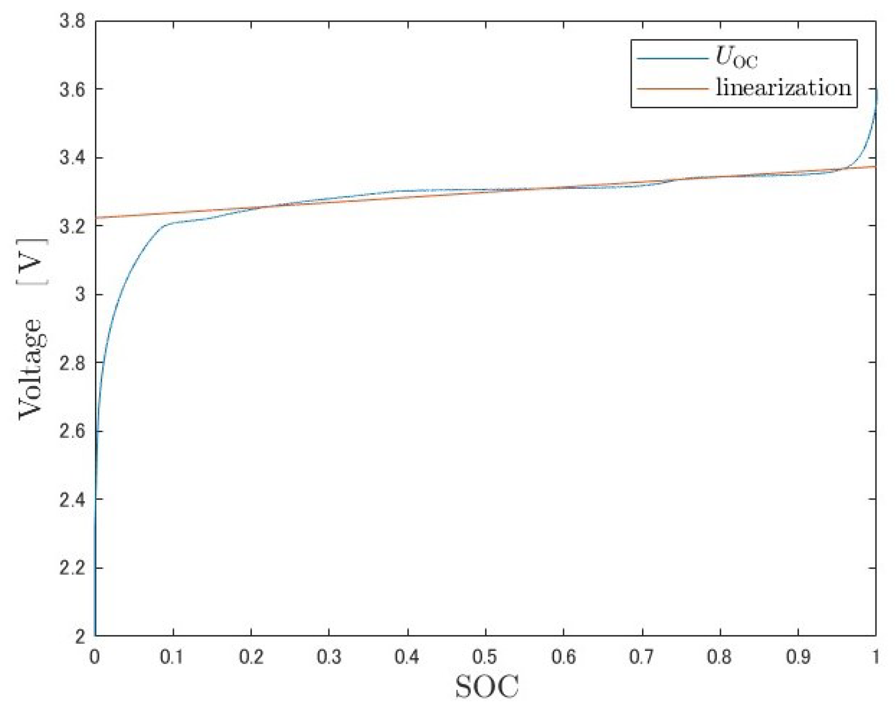
Although U OC ( SOC ( t ) ) in Equation (21) is a nonlinear function, it shows approximately linear behavior in the range of 0.1 < SOC ( t ) < 0.9 . Therefore, in this study, the range of 0.1 < SOC ( t ) < 0.9 is first-order approximated as follows:
U OC ( SOC ( t ) ) = a · SOC ( t ) + b
By the least-squares method, the coefficients are set to a = 0.1503 V , b = 3.2228 V . The result of the first-order approximation is shown in the following Figure 8.
From the above, Equation (21) can be rewritten as follows, where Y ( t ) : = U L ( t ) + R 0 I L ( t ) b is newly defined as the output after transposing the direct and constant terms from the right side.
Y ( t ) = 1 a 0 x ( t )
Furthermore, the system is converted to an observable canonical form.
D 0.5 x o ( t ) = A o x o ( t ) + b o I L ( t )
Y ( t ) = c o x o ( t )
where
x o ( t ) = U p ( t ) + a · SOC ( t ) a R p C p SOC ( t ) + a · D 0.5 SOC ( t ) a R p C p D 0.5 SOC ( t )
A o = 1 R p C p 1 0 0 0 1 0 0 0 , b o = 1 C p a η C n a R p C p η C n , c o = 1 0 0
The Kreisselmeier-type adaptive observer can estimate the first column of A o and all entries of b o , at most six entries. In this study, we adjust three of these six entries: the ( 1 , 1 ) entry of A o and the first and third entries of b o , which contains the unknown parameters R p , C p .

4.3. Proposed Adaptive Law

The battery model is a system with two unknown parameters R p , C p . However, the adaptive law in Equation (63) has three adjustable parameters, which increases the possibility that the parameters will converge to a local solution. Therefore, we propose an adaptive law with fewer adjustable parameters derived below by transforming the formula.
Substitute the specific expression for the observed object into Equation (61) and transform the expression as follows:
ϵ ( t ) = ζ ( t ) θ ˜ ( t ) = ζ 1 ( t ) ζ 2 ( t ) ζ 3 ( t ) ζ 4 ( t ) ζ 5 ( t ) ζ 6 ( t ) 1 R p C p 1 R ^ p ( t ) C ^ p ( t ) 0 0 1 C p 1 C p ^ ( t ) 0 a η C n ( 1 R p C p 1 R p ^ ( t ) C p ^ ( t ) ) = ζ 1 ( t ) ζ 2 ( t ) ζ 3 ( t ) ζ 4 ( t ) ζ 5 ( t ) ζ 1 ( t ) + a η C n ζ 6 ( t ) 0 0 0 1 C p 1 C p ^ ( t ) 0 1 R p C p 1 R p ^ ( t ) C p ^ ( t ) = ζ n ( t ) θ ˜ n ( t )
The gradient is calculated in the same way as for the first adaptation law, and the adaptation law can be derived as follows:
θ ^ ˙ n ( t ) = Γ ζ n ( t ) ϵ ( t ) 1 + ζ n ( t ) ζ n ( t ) , θ ^ n ( 0 ) = θ ^ n , 0 , Γ > 0
The proof of convergence is presented in a similar procedure. This reduces the number of adjustable parameters while keeping the observer stable.

5. Results and Discussion

The following three types of observers were used to simulate SOC estimation.
  • Fractional-order Luenberger observer;
  • Fractional-order Kreisselmeier adaptive observer with adaptive law Equation (63);
  • Fractional-order Kreisselmeier adaptive observer with adaptive law Equation (73).
The specification of the battery is shown in Table 1 and simulation conditions are shown in Table 3. The values of the model parameter from Table 2 obtained by offline optimization were taken as true values. An initial error of + 5 % was given for R p , C p . The initial value of SOC was 0.735, and the initial estimate was given an error of + 10 % .
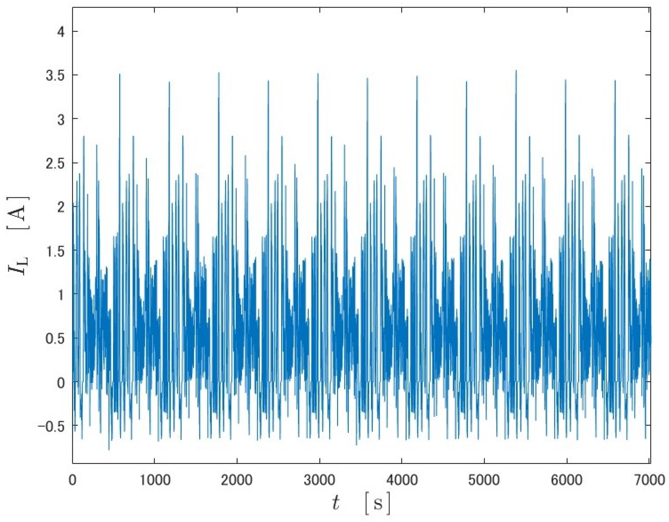
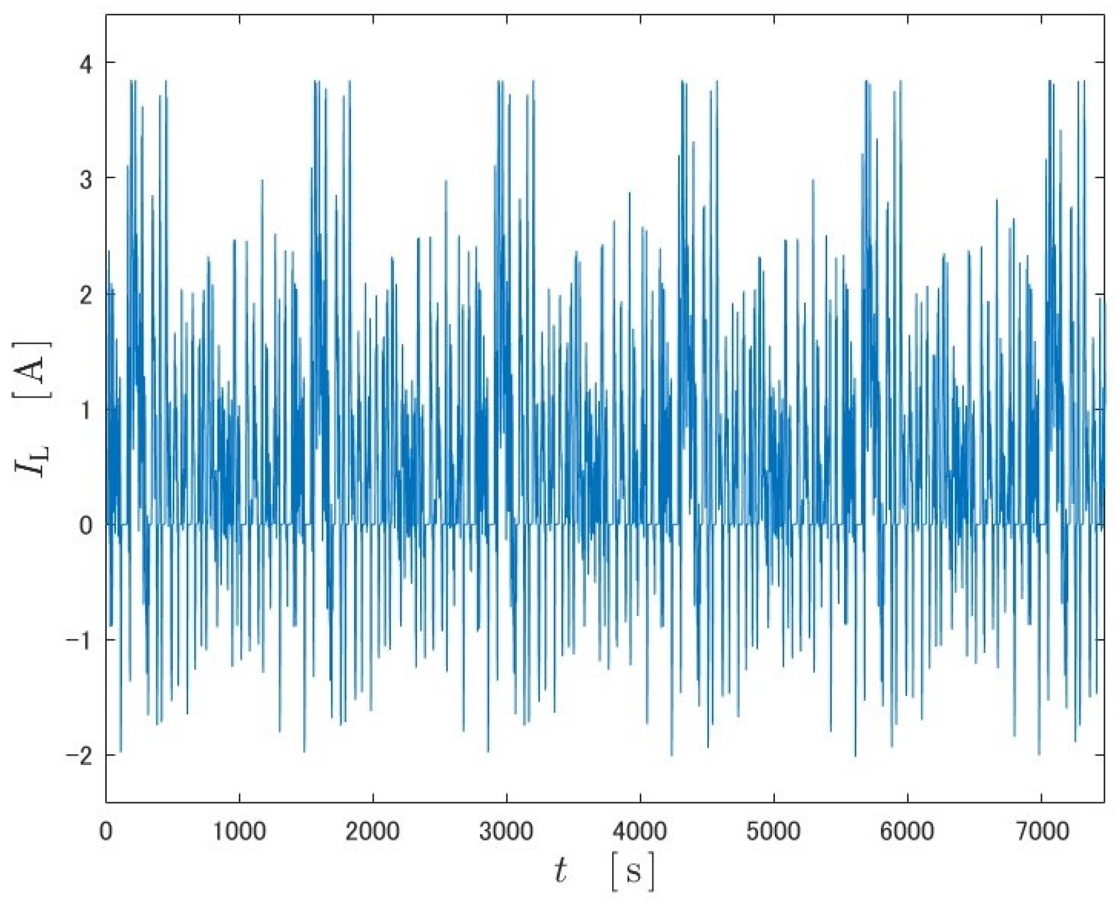
Simulations were run on two different datasets, US06 and FUDS. The inputs are shown in Figure 9 and Figure 10, and the output data are the output obtained through the equivalent circuit model. The datasets are mainly discharging scenarios, but a few charging scenarios are included.
In the simulations, the observer design parameters were adjusted for each. The design parameters of the proposed observer (adaptive law Equation (73)) were set as follows:
f = 3 3 1
Γ = 0 0 0 0 0 0 0 0 0 0 0 0 0 0 0 0 0 0 0 0 0 20 0 0 0 0 0 0 0 0 0 0 0 0 0 1.1 × 10 5
The design parameters of the Manabe approach are j = 15 , k = 5 , δ = 1.2 .

5.1. US06

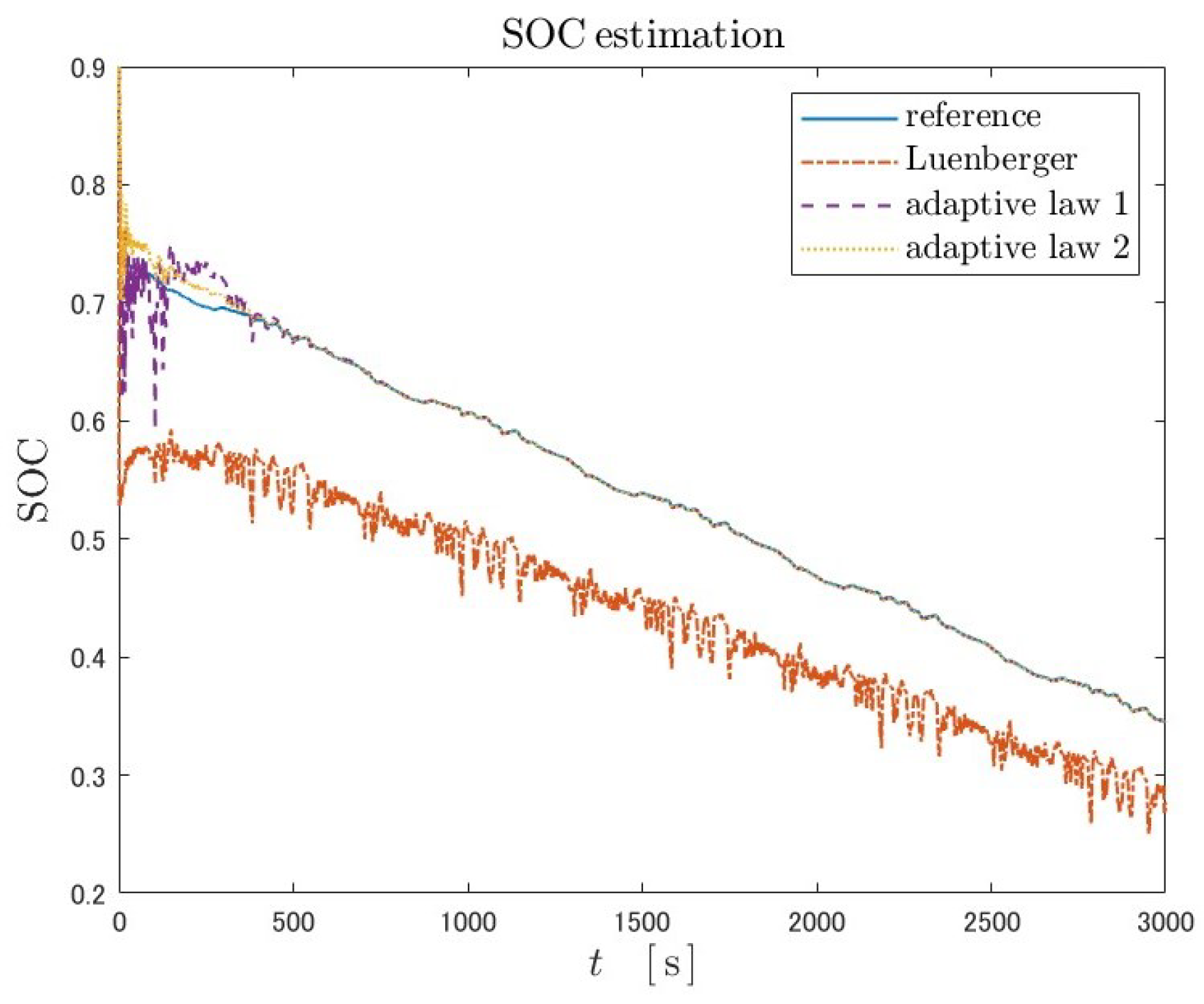
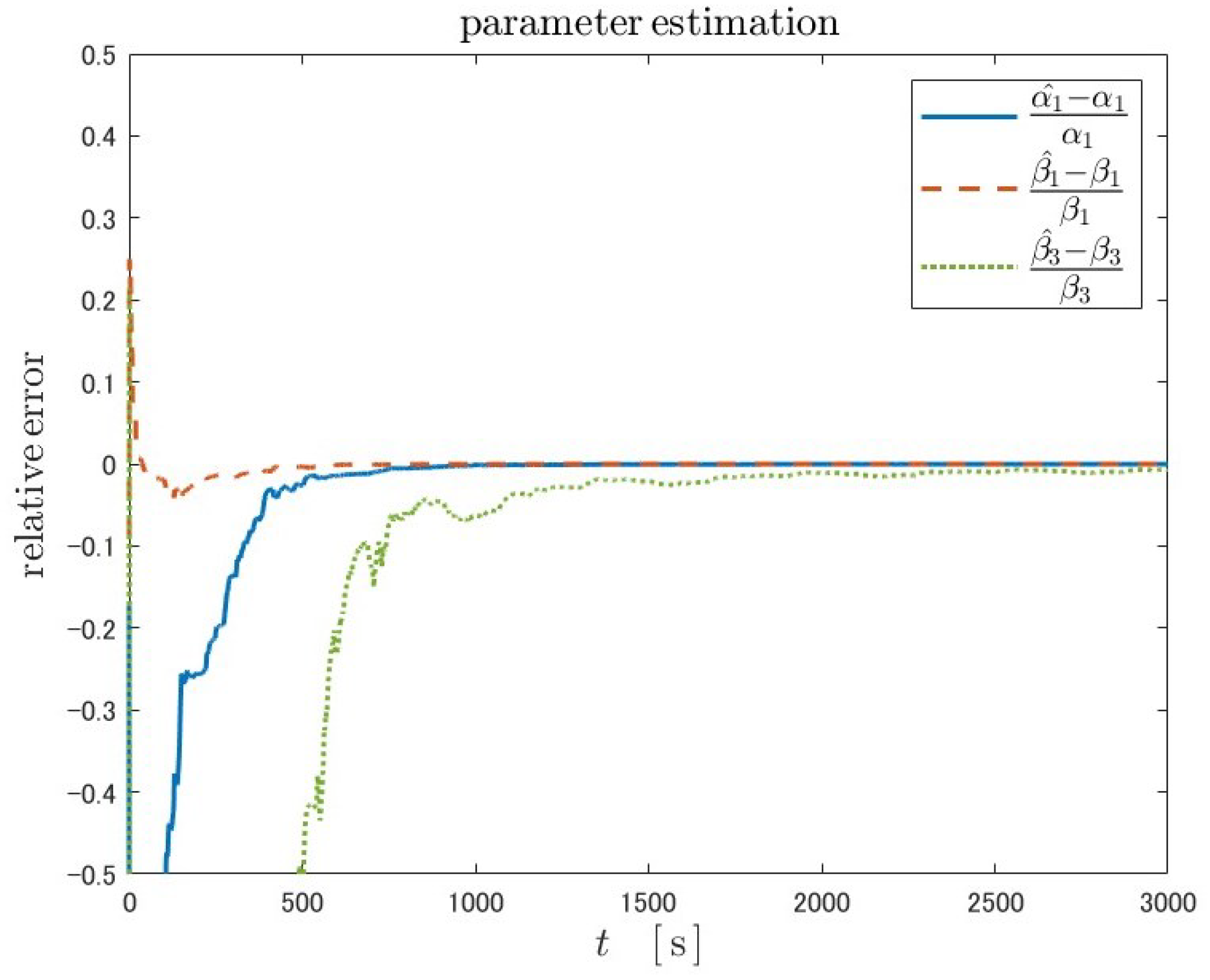
The simulation results using US06 are shown below Figure 11, Figure 12 and Figure 13.
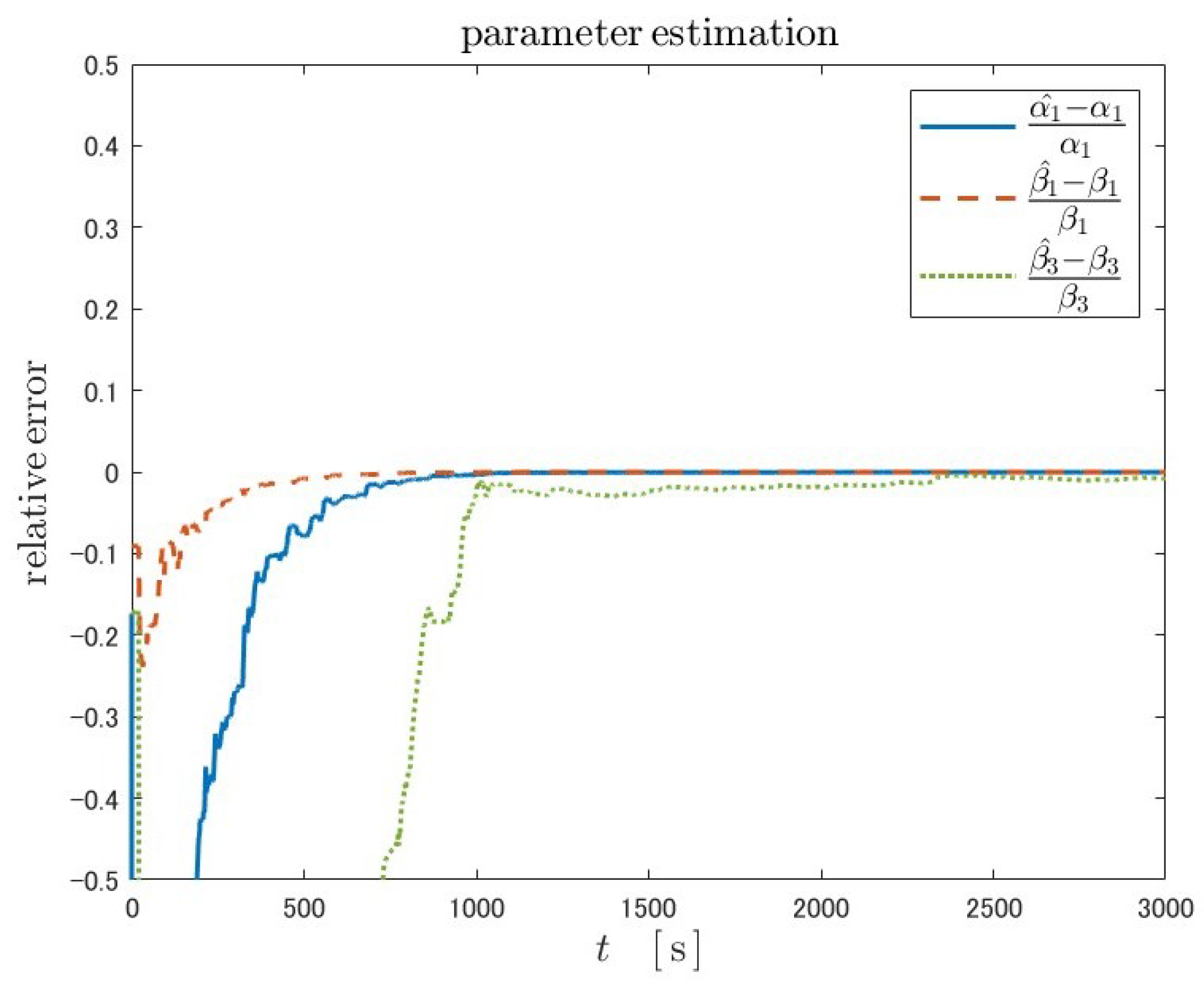
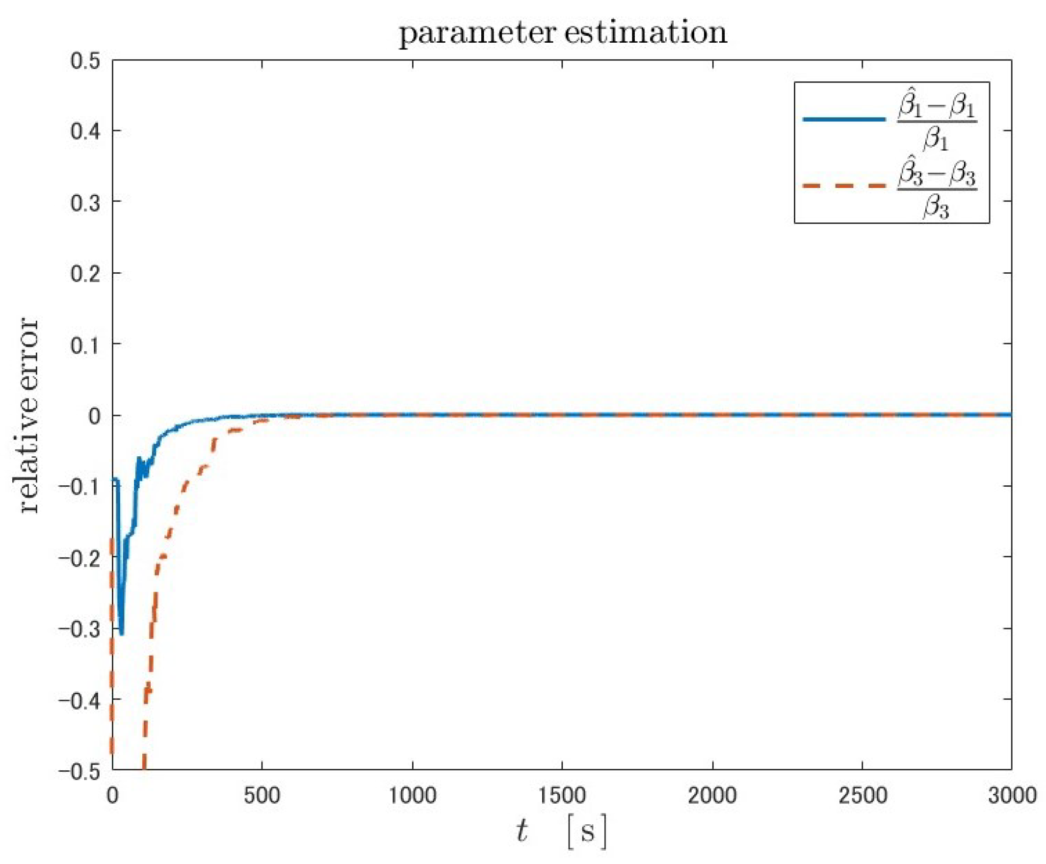
Because Luenberger-type observers are not adaptive, the state estimate will never converge to the true value when the plant parameters are unknown. As in the case of fractional-order Kreisselmeier adaptive observers of both adaptive laws, due to the adaptability, the parameters converge to true values. As a result, the SOC estimates also converge to the true values in both adaptive laws. The overshoot near the initial time in the parameter estimation with adaptive law 2 is smaller than that with adaptive law 1.
The Table 4 and Table 5 show the estimation accuracy and convergence time for two adaptive laws, where the mean absolute error (MAE) of the estimation error is calculated as a measure of the SOC estimation accuracy. The convergence time is defined as the time at which the error falls below the tolerance and then does not exceed the tolerance again. A value of 0.01 was set as the tolerance for the SOC estimation error, and 0.03 and 0.01 for the parameter errors. The Luenberger-type observer was excluded from this table because it did not adjust parameters and SOC estimation never converged.
Table 4 shows that the estimation accuracy is better for adaptive law 2. Table 5 also shows that the convergence time of SOC is better for adaptive law 2. This can be explained by the fact that the parameters converge to their true values in a shorter time in adaptive law 2. The reason for the shorter convergence time of the parameters can be attributed to the fact that convergence is easier due to the reduced number of adjustable parameters.

5.2. FUDS

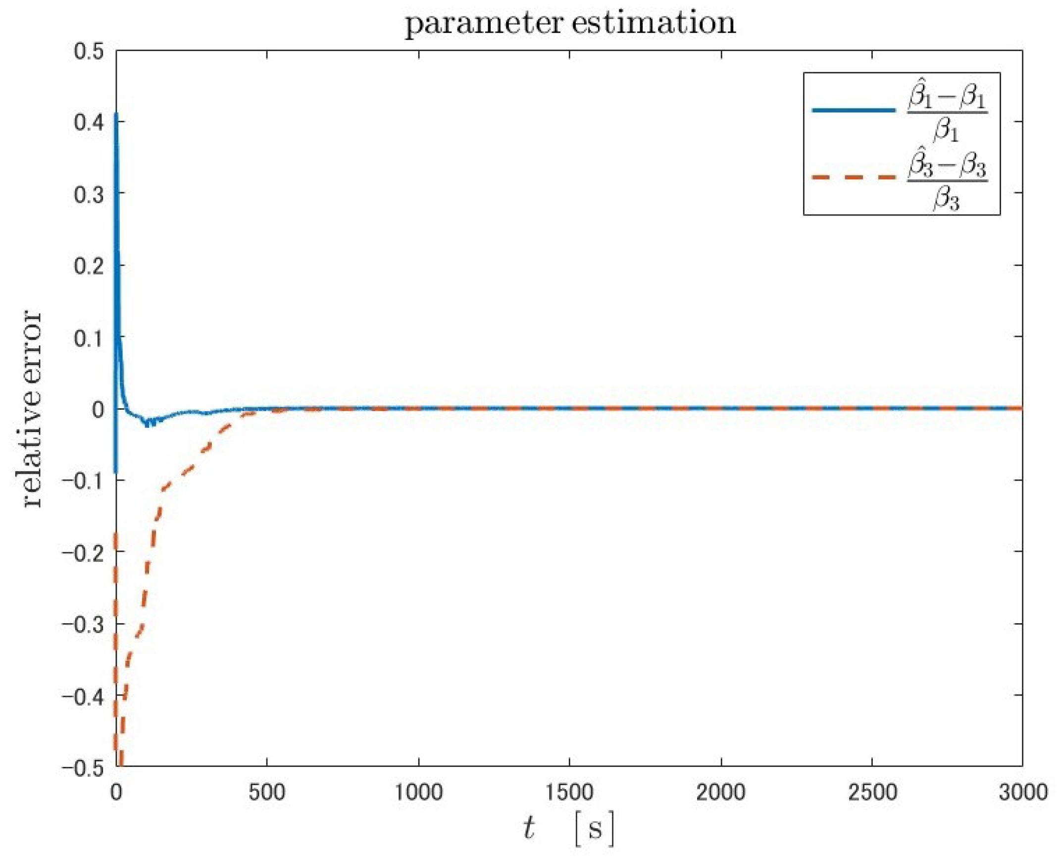
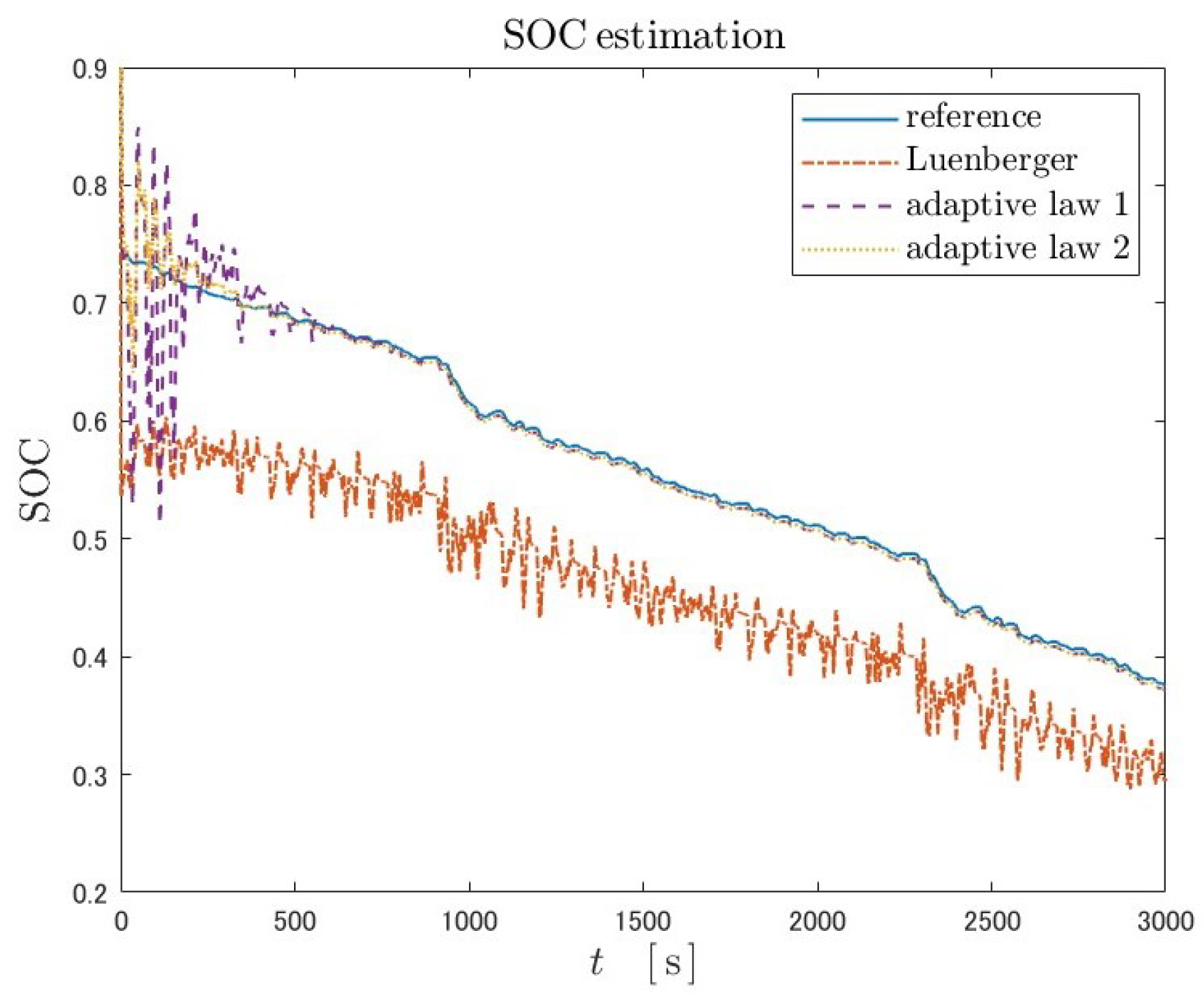
Simulation result using FUDS are shown below Figure 14, Figure 15 and Figure 16 and Table 6 and Table 7.
Similar trends to US06 are found: SOC estimation by the Luenberger-type observer did not converge to the true value; adaptive law 2 is superior to adaptive law 2 in terms of the convergence time of SOC and parameters.

6. Conclusions

In this study, we confirmed the superiority of the fractional-order model over the integer-order model of the battery and simulated the SOC estimation. When an observer was applied to the equivalent circuit model, SOC and model parameters could be estimated by using an adaptive fractional-order Kreisselmeier-type observer. The convergence and estimation accuracy were improved by changing the adaptive law to combine redundant adjustable parameters while maintaining the stability of the observer.
In the simulation of SOC estimation conducted in this study, an equivalent circuit model was set up as a plant. For practical use, real data should also be used for the plant output. In addition, various restrictions were attached, such as not including disturbances, the range of SOC for linearization of OCV, making R 0 known, and not explicitly considering the effect of temperature. These should be addressed in future studies.
Author Contributions

Conceptualization, T.M. and H.O.; methodology, T.M.; software, T.M.; validation, T.M.; writing—original draft preparation, T.M.; writing—review and editing, T.M.; visualization, T.M.; supervision, H.O. All authors have read and agreed to the published version of the manuscript.

Funding

This article is based on results obtained from a project, JPNP21014, subsidized by the New Energy and Industrial Technology Development Organization (NEDO).

Data Availability Statement

The data that support the findings of this study are available from the corresponding author upon reasonable request.

Conflicts of Interest

The authors declare no conflicts of interest.

References

  1. Li, Z.; Khajepour, A.; Song, J. A comprehensive review of the key technologies for pure electric vehicles. Energy 2019, 182, 824–839. [Google Scholar] [CrossRef]
  2. Si, C.; Liu, W.; Chau, K.T.; Jiang, C. Perspectives on Lithium-Based Batteries and Post-Lithium Batteries for Electric Vehicles. In Proceedings of the 2022 IEEE 13th International Symposium on Power Electronics for Distributed Generation Systems, Kiel, Germany, 26–29 June 2022. [Google Scholar]
  3. Shete, S.; Jog, P.; Kumawat, R.K.; Palwalia, D.K. Battery Management System for SOC Estimation of Lithium-Ion Battery in Electric Vehicle: A Review. In Proceedings of the 2021 6th IEEE International Conference on Recent Advances and Innovations in Engineering, Kedah, Malaysia, 1–3 December 2021. [Google Scholar]
  4. Xiang, L.; Cai, L.; Shi, J.; Gao, L.; Xu, Q. Review on development and application of SOC key technologies for electric vehicle battery packs. In Proceedings of the 2021 IEEE Sustainable Power and Energy Conference, Nanjing, China, 23–25 December 2021. [Google Scholar]
  5. Hannana, M.A.; Lipub, M.S.H.; Hussain, A.; Mohamed, A. A review of lithium-ion battery state of charge estimation and management system in electric vehicle applications: Challenges and recommendations. Renew. Sustain. Energy Rev. 2017, 78, 834–854. [Google Scholar] [CrossRef]
  6. Meng, J.; Ricco, M.; Luo, G.; Swierczynski, M.; Stroe, D.I.; Stroe, A.I.; Teodorescu, R. An Overview and Comparison of Online Implementable SOC Estimation Methods for Lithium-Ion Battery. IEEE Trans. Ind. Appl. 2018, 54, 1583–1591. [Google Scholar] [CrossRef]
  7. David, T.; Swan, L. Characteristics of Open Circuit Voltage Relaxation in Lithium-Ion Batteries for the Purpose of State of Charge and State of Health Analysis. Batteries 2022, 8, 77. [Google Scholar] [CrossRef]
  8. Xing, Y.; He, W.; Pecht, M.; Tsui, K.L. State of charge estimation of lithium-ion batteries using the open-circuit voltage at various ambient temperatures. Appl. Energy 2014, 113, 106–115. [Google Scholar] [CrossRef]
  9. Lavigne, L.; Sabatier, J.; Francisco, J.M.; Guillemard, F.; Noury, A. Lithium-ion Open Circuit Voltage (OCV) curve modelling and its ageing adjustment. J. Power Sources 2016, 324, 694–703. [Google Scholar] [CrossRef]
  10. How, D.N.T.; Hannan, M.A.; Lipu, M.S.H.; Sahari, K.S.M.; Ker, P.J.; Muttaqi, K.M. State-of-Charge Estimation of Li-ion Battery in Electric Vehicles: A Deep Neural Network Approach. In Proceedings of the 2019 IEEE Industry Applications Society Annual Meeting, Baltimore, MD, USA, 29 September–3 October 2019. [Google Scholar]
  11. Lipu, M.H.; Hannan, M.A.; Hussain, A.; Ayob, A.; Saad, M.H.; Karim, T.F.; How, D.N. Data-driven state of charge estimation of lithium-ion batteries: Algorithms, implementation factors, limitations and future trends. J. Clean. Prod. 2020, 277, 124110. [Google Scholar] [CrossRef]
  12. Wang, J.; Meng, J.; Peng, Q.; Liu, T.; Zeng, X.; Chen, G.; Li, Y. Lithium-Ion Battery State-of-Charge Estimation Using Electrochemical Model with Sensitive Parameters Adjustment. Batteries 2023, 9, 180. [Google Scholar] [CrossRef]
  13. Yu, Z.; Huai, R.; Xiao, L. State-of-Charge Estimation for Lithium-Ion Batteries Using a Kalman Filter Based on Local Linearization. Energies 2015, 8, 7854–7873. [Google Scholar] [CrossRef]
  14. Cui, Z.; Hu, W.; Zhang, G.; Zhang, Z.; Chen, Z. An extended Kalman filter based SOC estimation method for Li-ion battery. Energy Rep. 2022, 8, 81–87. [Google Scholar] [CrossRef]
  15. Chen, Z.; Yang, L.; Zhao, X.; Wang, Y.; He, Z. Online state of charge estimation of Li-ion battery based on an improved unscented Kalman filter approach. Appl. Math. Model. 2019, 70, 532–544. [Google Scholar] [CrossRef]
  16. Vermeer, W.; Mouli, G.R.C.; Bauer, P. A Comprehensive Review on the Characteristics and Modeling of Lithium-Ion Battery Aging. IEEE Trans. Transp. Electrif. 2022, 8, 2205–2232. [Google Scholar] [CrossRef]
  17. Wei, Y.; Ling, L. State-of-Charge Estimation for Lithium-Ion Batteries Based on Temperature-Based Fractional-Order Model and Dual Fractional-Order Kalman Filter. IEEE Access 2022, 10, 37131–37148. [Google Scholar] [CrossRef]
  18. Yang, Q.; Xu, J.; Cao, B.; Li, X. A simplified fractional order impedance model and parameter identification method for lithium-ion batteries. PLoS ONE 2017, 12, E0172424. [Google Scholar] [CrossRef] [PubMed]
  19. Takamatsu, T.; Ohmori, O. State and parameter estimation of lithium-ion battery by Kreisselmeier-type adaptive observer for fractional calculus system. In Proceedings of the 2015 54th Annual Conference of the Society of Instrument and Control Engineers of Japan, Hangzhou, China, 28–30 July 2015. [Google Scholar]
  20. Guo, R.; Shen, W. Lithium-Ion Battery State of Charge and State of Power Estimation Based on a Partial-Adaptive Fractional-Order Model in Electric Vehicles. IEEE Trans. Ind. Electron. 2023, 70, 10123–10133. [Google Scholar] [CrossRef]
  21. Caputo, M. Linear Models of Dissipation whose Q is almost Frequency Independent—II. Geophys. J. Int. 1967, 13, 529–539. [Google Scholar] [CrossRef]
  22. Caputo, M.; Mainardi, F. A New Dissipation Model Based on Memory Mechanism. Pure Appl. Geophys. 1971, 91–98, 134–147. [Google Scholar] [CrossRef]
  23. Manabe, H. On fractional-order integral control systems. J. Inst. Electr. Eng. Jpn. 1960, 80–85, 589–597. (In Japanese) [Google Scholar]
  24. Battery Data. Available online: https://calce.umd.edu/battery-data (accessed on 1 July 2023).
  25. Kreisselmeier, G. Adaptive observer with exponential rate of convergence. IEEE Trans. Autom. Control 1977, AC-22, 2–8. [Google Scholar] [CrossRef]
Figure 1. The graph of D t q 0 [ x 0.5 ] .
Machines 12 00738 g001
Figure 2. Schematic diagram of the Manabe approach.
Machines 12 00738 g002
Figure 3. The OCV-SOC curve at 30 °C.
Machines 12 00738 g003
Figure 4. The fractional-order equivalent circuit diagram.
Machines 12 00738 g004
Figure 5. The integer-order equivalent circuit diagram.
Machines 12 00738 g005
Figure 6. Time series of battery current I L ( t ) at DST.
Machines 12 00738 g006
Figure 7. Time series of terminal voltage U L ( t ) at DST.
Machines 12 00738 g007
Figure 8. The result of first-order approximation of the OCV-SOC curve.
Machines 12 00738 g008
Figure 9. Time series of battery current I L ( t ) at US06.
Machines 12 00738 g009
Figure 10. Time series of battery current I L ( t ) at FUDS.
Machines 12 00738 g010
Figure 11. Simulation results of SOC estimation under the US06 test by the fractional-order Luenberger observer and fractional-order Kreisselmeier adaptive observer with adaptive law 1 and 2.
Machines 12 00738 g011
Figure 12. The result of parameter estimation under the US06 test using fractional-order Kreisselmeier adaptive observer with adaptive law 1.
Machines 12 00738 g012
Figure 13. The result of parameter estimation under the US06 test using fractional-order Kreisselmeier adaptive observer with adaptive law 2.
Machines 12 00738 g013
Figure 14. Simulation results of SOC estimation under the FUDS test by the fractional-order Luenberger observer and fractional-order Kreisselmeier adaptive observer with adaptive law 1 and 2.
Machines 12 00738 g014
Figure 15. The result of parameter estimation under the FUDS test using fractional-order Kreisselmeier adaptive observer with adaptive law 1.
Machines 12 00738 g015
Figure 16. The result of parameter estimation under the FUDS test using fractional-order Kreisselmeier adaptive observer with adaptive law 2.
Machines 12 00738 g016
Table 1. Battery specification.
ParameterValue
nominal capasity 1100 mAh
nominal voltage 3.3 V
maximum discharge current 30 A
upper cut-off voltage 3.6 V
lower cut-off voltage 2.0 V
Table 2. Offline optimization result.
Model ParameterFractional OrderInteger Order
R ^ 0 0.145 Ω 0.158 Ω
R ^ p 0.0618 Ω 0.0530 Ω
C ^ p 168 F 1.17 × 10 3 F
RMSE 6.3 mV 9.7 mV
Table 3. True values and initial values of the simulation.
True ValueInitial Value
R p 0.0618 Ω 0.0649 Ω
C p 168 F 176 F
initial SOC0.7350.809
Table 4. Comparison of SOC estimation accuracy under the US06 test between adaptive law 1 and 2.
Adaptive Law 1Adaptive Law 2
MAE0.00390.0024
Table 5. Comparison of SOC and parameter convergence time under the US06 test between adaptive law 1 and 2.
Adaptive Law 1Adaptive Law 2
SOC (tolerance: 0.01) 386 s 300 s
parameter (tolerance: 0.03) 1212 s 357 s
parameter (tolerance: 0.01) 2831 s 422 s
Table 6. Comparison of SOC estimation accuracy under the FUDS test between adaptive law 1 and 2.
Adaptive Law 1Adaptive Law 2
MAE0.01000.0059
Table 7. Comparison of SOC and parameter convergence time under the FUDS test between adaptive law 1 and 2.
Adaptive Law 1Adaptive Law 2
SOC (tolerance: 0.01) 554 s 295 s
parameter (tolerance: 0.03) 1404 s 364 s
parameter (tolerance: 0.01) 2827 s 484 s
Disclaimer/Publisher’s Note: The statements, opinions and data contained in all publications are solely those of the individual author(s) and contributor(s) and not of MDPI and/or the editor(s). MDPI and/or the editor(s) disclaim responsibility for any injury to people or property resulting from any ideas, methods, instructions or products referred to in the content.