1. Introduction
With the enhancement of individuals’ material living standards, an increasing number of people are directing their attention toward the holistic development of physical and mental well-being [
1]. Badminton, being an exceptionally dynamic and competitive sport, demands athletes to possess advanced serving skills, and the capability to serve with precision and variety is pivotal for securing an advantage on the court [
2,
3]. In conventional training methods, coaches are required to repeatedly demonstrate various serve techniques over an extended period. As time progresses, the physical fatigue experienced by training coaches may result in the deformation of technical movements. This, in turn, contributes to a decline in serving accuracy and a gradual increase in ineffective feeds, thereby diminishing the overall training effectiveness [
4].
The introduction of badminton serving devices offers an effective solution to address the challenges associated with unstable play and insufficient technical proficiency among training coaches. This, in turn, mitigates the limited effectiveness of training and brings about a notable enhancement in training methodologies [
5]. The use of badminton serving devices can provide a controlled and adaptable practice environment for athletes, enabling them to fine-tune their serving technique and improve their overall level.
The serving method, serving as the focal point in the design of badminton serving devices, has been a predominant research focus for scholars globally. Currently, two primary mainstream serving modes exist. The first is founded on the fixed-position badminton serving method, wherein trainers modify the hardware structure and placement position of the serving device to alter the serving angle and achieve varying serve distances [
6]. This method boasts a relatively uncomplicated mechanical mechanism, facilitating straightforward daily maintenance. However, its drawbacks are conspicuous: each transition to a different serve mode necessitates manual adjustments to the structure, resulting in a singular serve mode with lower precision.
The second approach involves the serving method based on an embedded control system, wherein an embedded control system is integrated into the traditional serving device. Trainers can adjust serving parameters in response to training requirements, and the serving device, in turn, modifies its hardware structure based on these parameters, enabling fully automated serving [
7,
8]. Prior literature introduces a Badminton Shuttlecock Feeding Machine that employs trajectory simulation to derive initial parameters, saving them within the Feeding Machine for the automatic launch of four distinct types of initial balls [
9]. Prior literature [
10] proposes a design of a high-speed, lightweight humanoid badminton robot. Its structure integrates a pneumatic actuator and non-interference multi-degree-of-freedom joint to achieve high-precision motion control. In contrast to the first method, this approach utilizes an embedded system to govern the mechanical structure of the ball-launching device, significantly enhancing launch accuracy. The method can also store different parameters of the ball launching patterns, providing trainers with a variety of launching methods. However, a drawback lies in the need for manual adjustment of the embedded system when altering the serve mode, the lack of automatic remote adjustment, and the need for further enhancement in terms of intelligence.
In recent years, with the advancing capabilities of computer vision technology, scholars have progressively integrated computer vision into badminton serving devices [
11]. Prior literature [
12] explores a badminton serving robot that employs visual recognition technology to identify badminton balls released by the ball feeding mechanism. The robot is equipped with a badminton racket attached to its arm, allowing it to strike the balls with the racket to perform the serving action. Another work [
13] introduces a badminton-hitting robot featuring a distance image sensor. This robot detects the flight trajectory of the badminton ball through the sensor, predicts the landing point based on the distance image, and adjusts its position accordingly to strike the ball back with the racket. Additionally, prior literature [
14] presents a badminton robot that captures and analyzes athletes’ batting videos using a camera on the serving device, thereby enhancing the serving device’s intelligence. However, despite these advancements in integrating computer vision technology with badminton serving devices, the method of serving the badminton serving device has not been modified, and the type of serving is still changed by manually adjusting the embedded system.
To address the challenges encountered by existing badminton serving devices, such as the necessity for manual adjustment of the embedded system’s serving mode and the lack of automatic adaptation to the player’s state, this paper proposes a design method for a badminton serving device based on visual perception and multimodal control. This method involves acquiring the player’s posture image through the posture recognition module installed on the badminton ball serving device. The collected image undergoes posture recognition, and the signal control module is then manipulated to adjust the serving device’s angle, speed, and serve count based on the recognition results. Alternatively, the angle, speed, and serve count can be modified using the self-developed upper computer module that governs the signal control module. Consequently, this method empowers athletes to practice various strokes within the hitting zone.
In this paper, computer vision’s posture recognition technology is seamlessly integrated with the badminton serving device, effectively enhancing the automation and intelligence of the existing system. In comparison to prior research, this paper distinguishes itself in two crucial aspects:
- (1)
This paper pioneers the utilization of human posture information as the primary control signal for a badminton serve device. Throughout its usage, the serve device dynamically adjusts the equipment’s height, speed, and angle based on the user’s distinct posture signals, facilitating a non-contact and automated service mode. This innovative approach not only enhances user experience but also streamlines the process of delivering services, promising significant advancements in the realm of badminton training and gameplay.
- (2)
This paper introduces an innovative posture detection process. In contrast to the benchmark detection process, the key point information identified in the image serves as feedback for the subsequent frame’s key point detection process. This approach reduces redundant posture mapping, thereby enhancing posture recognition speed.
The structure of the remaining sections in the paper is as follows:
Section 2 describes the system design of the badminton serving device.
Section 3 describes the overall hardware design of badminton serving device.
Section 4 describes the vision based human posture recognition method.
Section 5 describes the real serve test conducted to verify the accuracy and reliability of the serve device.
Section 6 provides concluding remarks.
2. System Design
The system design and operation flow of the badminton serving device, based on visual perception and multimodal control as proposed in the paper, is depicted in
Figure 1. The system comprises several key components, including the upper computer module, the posture recognition module, the signal control module, and the execution module. The upper computer module consists of both software and hardware components. The software component is a self-developed system responsible for selecting the posture recognition type and transmitting service signals to the signal control module. The posture recognition module is composed of a vision module and a microprocessor module. The vision module captures images of the human body posture, while the microprocessor module executes the posture recognition method to identify the posture, subsequently outputting the corresponding signal to the signal control module. The signal control module, in turn, receives signals from both the upper computer module and the posture recognition module. Its primary function is to direct the execution module in adjusting the mechanical structure of the ball-serving device. The execution module comprises a launch structure, a ball-plucking structure, and an angle adjustment structure. Upon receiving a control signal from the signal control module, the execution module dynamically adjusts each of these structures, culminating in the launch of the badminton ball.
When the serving device is in use, it can be controlled either by the posture recognition module based on the user’s posture or directly by the upper computer module. In the posture recognition mode, upon posture detection selection, the user’s posture image is initially transmitted from the vision module to the microprocessor module. Subsequently, the microprocessor module conveys the recognized posture signals to the signal control module. Ultimately, control signals are dispatched through the signal control module to regulate the mechanical structures of the execution module. Alternatively, in the event the user opts for the upper computer control mode, the initial step involves initiating the upper computer system. Following this, a communication connection must be established with the signal control module through the system interface. Subsequently, the user is required to configure the relevant parameters of the ball-launching device. Upon completing this setup, the badminton launching information is transmitted to the signal control module, allowing the badminton serving device to launch badminton at varying angles and speeds.
3. Overall Hardware Design
3.1. Mechanical Design of Actuator Modules
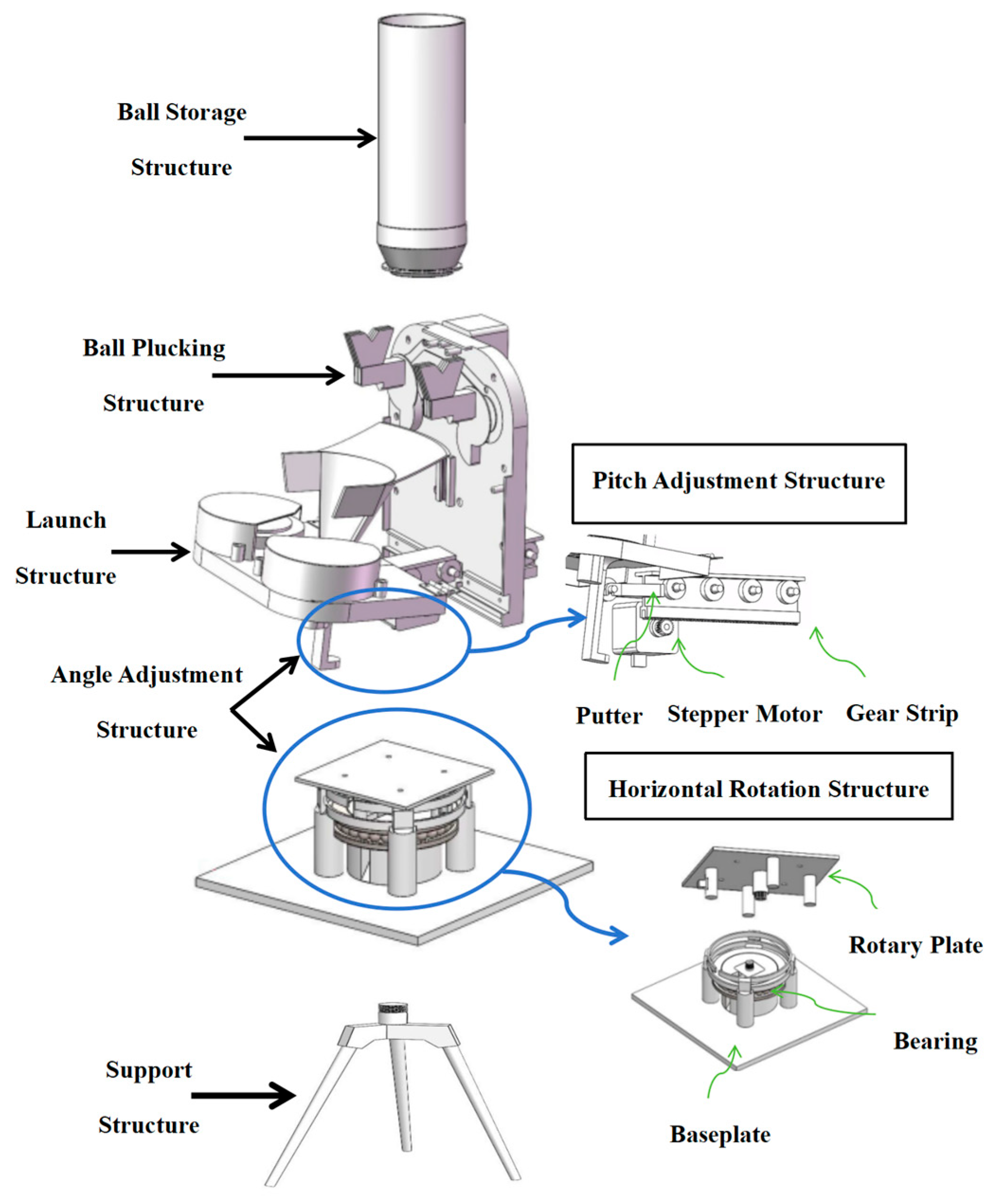
The design of the mechanical structure for the executive module of the badminton serving device is illustrated in
Figure 2. The module comprises key components: a ball storage structure, a ball plucking structure, a launch structure, an angle adjustment structure, and a support structure. The ball storage structure is tasked with housing the badminton balls and is composed of a cylindrical storage container. The ball-plucking structure extracts badminton balls from the storage cylinder to the ball rest using a configuration primarily comprising a pair of rubber paddles, DC motors, and gears. The launch structure is designed to propel the badminton balls, primarily employing friction wheels, DC motors, and protective shells.
The angle adjustment structure facilitates the adjustment of the badminton serving device’s angle in both horizontal and pitching directions. It comprises the horizontal rotation structure and the pitch adjustment structure.
The horizontal rotation structure comprises a bearing, a baseplate, a rotary plate, and a stepper motor; among them, the four columns on the turntable form an integral structure with the turntable, sharing the weight of the launch platform. The pitch adjustment structure includes a gear strip, a stepper motor, and a putter with a pulley. The support structure is tasked with providing support to the aforementioned four structures and is composed of a tripod.
The mechanical structure of the badminton serving devices operates on the principle that the launch angle requires adjustment before ball release. Horizontal angle adjustments are accomplished by a stepper motor that drives the rotary table to rotate horizontally. Furthermore, pitch angle adjustment is facilitated by an additional stepper motor driving the gear strip. This enables the push putter to move back and forth, thereby adjusting the pitch angle of the launch platform. Following the adjustment of the launch angle, it is essential to refine the initial speed of badminton release. This is achieved by modifying the rotation speed of the motor within the launch structure. Subsequently, the rubber paddle is propelled by the rotation of the paddle motor, extracting the badminton ball from the ball storage structure and placing it in the ball holder. Finally, the friction wheel within the launch structure propels the badminton balls.
3.2. Embedded Development Board Circuit Design
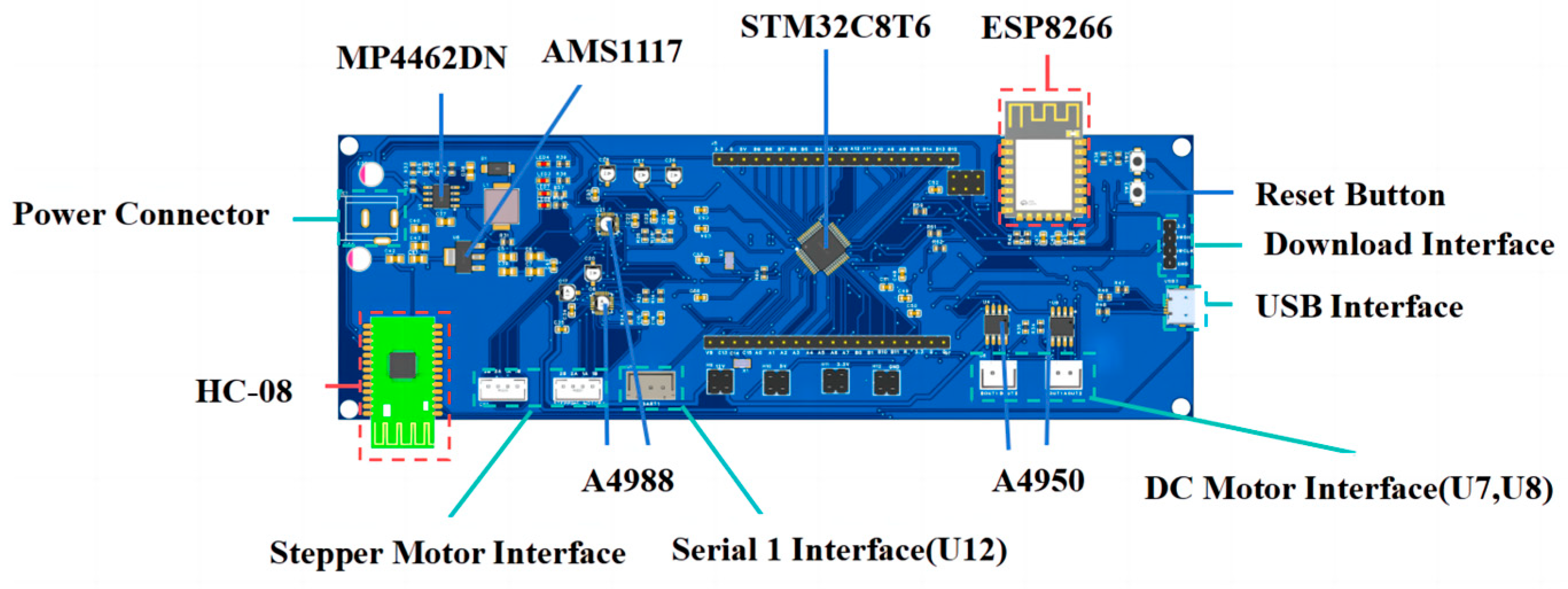
To address the functional requirements of the signal control module, this paper designs an embedded development board, the circuitry of which is illustrated in
Figure 3. The development board employs the STM32F103C8T6 chip as the main control chip and incorporates A4988 and A4950 chips as motor driver chips.
To accommodate the varied power supply voltages of the motor driver chip and the main control chip, a step-down circuit located on the left side of the development board. The circuit employs the MP4462DN chip along with a low dropout linear regulator. This combination, coupled with a multilayer ceramic capacitor and a low electromagnetic interference capacitor, effectively divides the input voltage to supply 5 V and 3.3 V outputs.
The embedded development board shown in
Figure 3 serves as the signal processing module in
Figure 1, which is connected to the attitude recognition module through the serial port one, and then connected to the host computer module through the WIFI module or the Bluetooth module, realizing the interaction between the attitude information and the control information. Meanwhile, the pivoting structure, launching structure, and rotating structure of the actuator module in
Figure 3 can be adjusted through the interface motor interface (stepper motor interface and DC motor interface) on it.
Upon establishing a wireless connection (WiFi or Bluetooth) between the upper computer module and the development board or when the posture recognition module interfaces through the serial port 1 interface (U12), the master control chip receives signals. The signals can originate either from the upper computer module through serial ports 3 or 2, alternatively, from the posture recognition module through serial port 1. After receiving the signals, the main control chip controls the operation of the two stepper motors (STEPING MOTOR1 and STEPING MOTOR2) in the angle adjustment module, utilizing timer TIM2 channels 1 and 2. Simultaneously, it regulates the two DC motors (U8 and U7) that are associated with the toggle and launching mechanisms using timer TIM3 channels 1 and 2. Ultimately, this leads to the execution of the serve.
4. Posture Recognition Methods
4.1. Posture Detection Principle
Detecting body postures poses a formidable challenge owing to the intricate nature of the human form [
15]. In contrast to rigid objects, the human body consists of numerous joints and displays a wide range of degrees of freedom in its limbs [
16]. Moreover, human postures exhibit high variability, and human limbs are particularly prone to occlusion and self-occlusion [
17].
BlazePose [
18] utilizes a detector-tracker setup to extract key point information about human body poses. The detector-tracker is composed of a body posture detector and a posture tracker; when there is an image input, the tracker predicts keypoint coordinates, and when the tracker indicates that there is no human present, re-run the detector network on the next frame. This method effectively improves the accuracy of the recognition of human body poses, and it is currently one of the most widely used methods [
19,
20]. Although this method can accurately identify information about the human body’s pose, the recognition process is run repeatedly for the same posture, resulting in a large computational burden and making it difficult to deploy on embedded computers. Therefore, in this paper, based on the original algorithm, We introduce a posture information comparison process and propose an improved Blazepose algorithm.
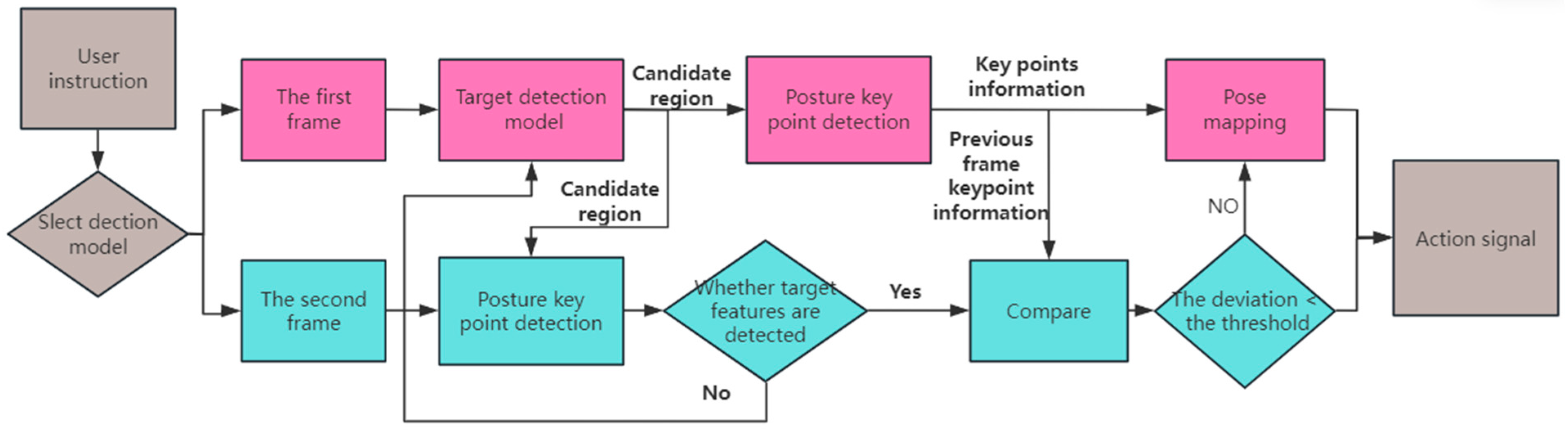
As illustrated in
Figure 4, the flowchart depicts the improved BlazePose algorithm. The process initiates with the user choosing between body detection or gesture detection. Upon inputting the first frame, it undergoes processing through the target detection model (palm detector or face detector). If target features, such as a face or palm, are present, a candidate region for the target location is generated. Then, keypoint detection is performed, where posture key points are detected by running a keypoint detection model (hand landmark model or pose landmark model) on the candidate region. After successfully detecting posture key points, the corresponding key point information is obtained. Ultimately, action signals are outputted following the matching of posture mapping information.
For the second frame input, the target detection process is skipped. Instead, the candidate region for the target position from the previous frame is extended to facilitate key point detection. If the extended candidate region fails to detect the target, the target detection model is reactivated. After obtaining key point detection information for the second frame, a pairwise comparison is initiated with the key point information from the previous frame. If the deviation in the comparison falls below a predefined threshold, it indicates a duplication of the posture action from the previous frame. As a result, the system directly outputs the same posture action as the previous frame without the need for matching the posture mapping information. Alternatively, if the comparison deviation exceeds the threshold, the system proceeds to match the posture mapping information and outputs the corresponding action signal. It is worth noting that in this paper, the target detection model and keypoint detection model are imported through the mediapipe library on Python(The version of Python is 3.7.3), and since this paper mainly addresses the problem of repeated recognition of the same posture, therefore, in this paper, the neural network is not trained and its parameters are not modified.
4.2. Attitude Mapping Creation
The key point information acquired through the aforementioned image key point detection process comprises the two-dimensional coordinates of each key point. Following the processing of the two-dimensional coordinates, they are compared with a pre-set posture action. If the comparison yields a match, the system outputs the action signal corresponding to the key point mapping.
Consider the human body posture of the “cross hand” action in
Figure 5 as an example. The posture can be recognized when the keypoint information satisfies the following four conditions or when it satisfies conditions (3) and (4) of higher priority: (1) dx < threshold
; (2) dy < threshold
; (3)
; (4)
. In this context, the posture is identified as a “cross hand”. Here, dx and dy are given by:
In the gesture detection segment, upon acquiring the coordinate information of the hand’s key points, the system calculates the distance between the key points and the joint curvature of a single finger. Subsequently, customized semantic judgment is applied to recognize the gesture, achieving system-wide gesture recognition.
The thumb joint nodes 1-2-3-4 are depicted in
Figure 6. With the known coordinates of key points 2, 3, and 4, the angle α
1 between and is determined using spatial distance, vector dot product, and the inverse trigonometric function. The formulas for these calculations are presented in Equations (3)–(5).
If α1 exceeds the threshold value, the joint is categorized as “straight”; conversely, if α1 is below the threshold value, the joint is labeled as “bent”. Applying the same methodology, the angle α2 for the key nodes 1-2-3 can be calculated. If α2 is less than the threshold value, it denotes the bending of joint 2. Additionally, if all other joints are “straight” simultaneously, the recognized gesture action is identified as “gesture 4”.
Practical scenarios involving the badminton serving device frequently require the execution of actions like continuous ball serving, serving a near netball, serving a mid-court ball, serving a high long ball, and others. In alignment with the previously outlined principles, the design includes control interaction instructions illustrated in
Figure 7 and
Figure 8.
Figure 7 shows the body posture, which includes four actions, namely raising the right hand (a), the left hand (b), raising both hands (c) and crossing the hands (d), and
Figure 8 shows the gesture actions, which we defined a total of nine groups of actions, in addition to the most common 1, 2, 3, 4, 5, 6 actions, adding the thumb action (g), then the gun action (h), and then the heart action (i). These different motions represent different control commands; for example, for the high ball command, there is the raising both hands (c) and the gun action (h), etc.
4.3. Posture Recognition Accuracy Evaluation
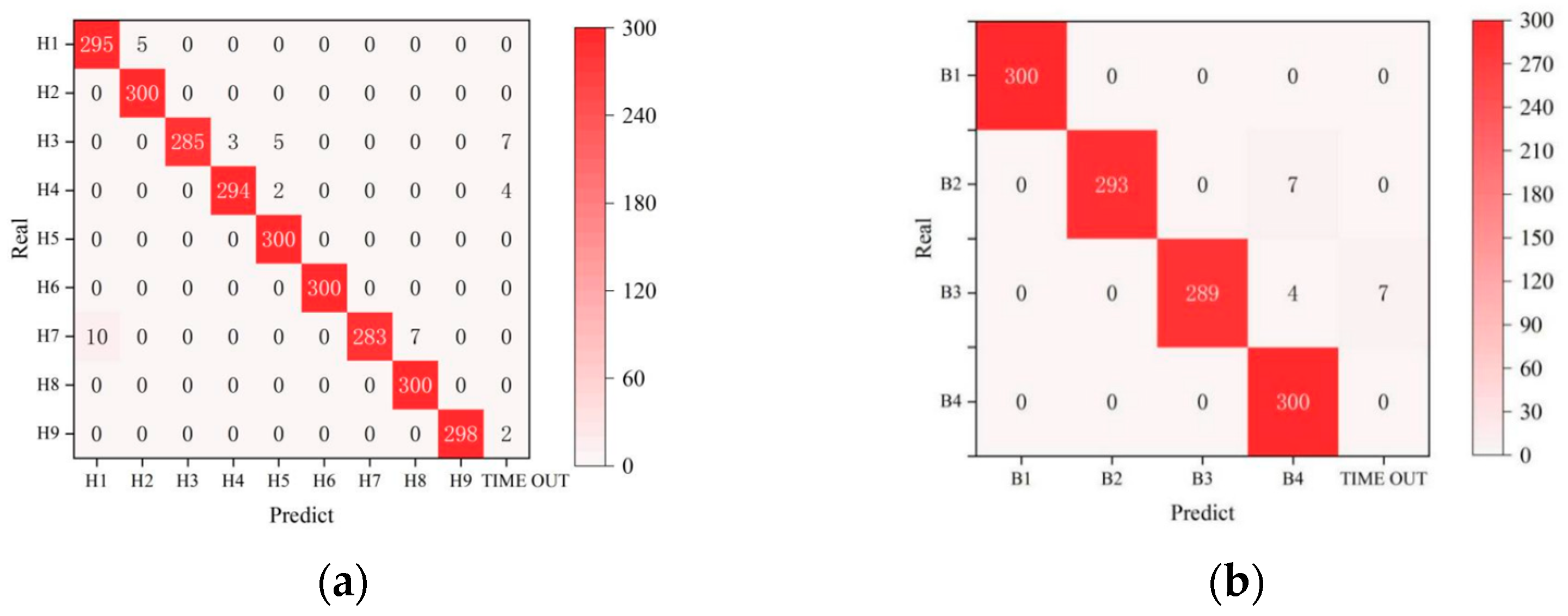
To validate the effectiveness and accuracy of the posture recognition method in this paper, recognition tests were conducted on the defined action commands. Ten experimenters in a badminton court participated in a recognition test for body posture instructions, with each experimenter performing single posture recognition 30 times. To simulate stadium usage, 15 instances involved detecting partial masking of the target, resulting in a total of 300 tests for each posture type and 2900 samples tested overall.
The confusion matrix, based on the test results, is presented in
Figure 9. In the matrix, “TIME OUT” denotes results not recognized for more than 2 s. The labels B1–B4 and H1–H9 represent control interaction instructions. The proposed posture recognition method successfully identifies B1, B4, H2, H5, H6, and H8 300 times, showcasing commendable recognition accuracy. However, challenges arise with misrecognition and recognition timeouts during the identification of B2 and B3.
To further assess the method’s strengths and weaknesses, three metrics—precision rate of detection (Pr), recall rate (Re), and accuracy rate (Ac) are applied to the statistical results of the confusion matrix, providing a more standardized measure [
21].
Pr denotes the precision rate of recognition, i.e., the ratio of the number of correct recognition to the total number of recognition in each type of posture action recognition [
22].
TP denotes the number of times the posture action was correctly recognized in this posture action recognition; FP denotes the number of times the posture action was recognized as the posture action in other posture action recognition.
Re denotes the recall of recognition, i.e., the ratio of the number of correctly recognized posture actions to the number of times the posture action is recognized.
FN denotes the number of times other posture actions are recognized in that posture action recognition.
Ac denotes the accuracy of recognition, i.e., the total number of all actions correctly recognized as a percentage of the total number of tests.
TN denotes the number of times a posture action is correctly recognized among other posture action recognition.
The accuracy indices for posture action detection are presented in
Table 1. From the table, it can be seen that: the average recognition precision
Pr of the nine gesture actions is 97.68%, the recall
Re is 98.66%, and the accuracy
Ac is 99.59%; the average recognition precision
Pr of the four body postures is 98.01%, the recall
Re is 98.34%, and the accuracy
Ac is 99.08%. In summary, the values of the above three performance evaluation indexes are all above 97%, thus indicating that the method has a good recognition effect. However, when the posture actions are H1, H5, H8 and B4, the accuracy of the above posture actions is lower compared to other actions, and from the aspect of recall, the recall of posture actions H3, H7 and B3 is low, The analysis is due to the detection model in the background environment is complex, the human body or palm segmentation is not accurate and similar action between the discrimination is inaccurate; in addition, the current recognition methods and vision module on the acquisition of action information frame rate is not high and caused by the recognition process of some of the semantic information is lost, resulting in the recognition of inaccurate or recognition of overtime problems, and ultimately will affect the above evaluation indexes.
6. Conclusions
In this paper, we propose a design method for a badminton serving device based on visual perception and multimodal control, comprising five modules: the upper computer module, the posture recognition module, the signal control module, and the execution module. We individually design the angle adjustment structure, launch structure, and ball plucking structure of the execution module to meet the specific requirements of the ball serving device. To address the needs of the signal control module, we independently design an embedded development board integrating the motor drive chip, wireless communication module, and step-down circuit. In the posture recognition method section, we introduce the image posture detection process. The key point information recognized in the previous frame of the image is input into the detection process of the next frame, preventing the repeated recognition of the same posture and enhancing the speed of posture recognition.
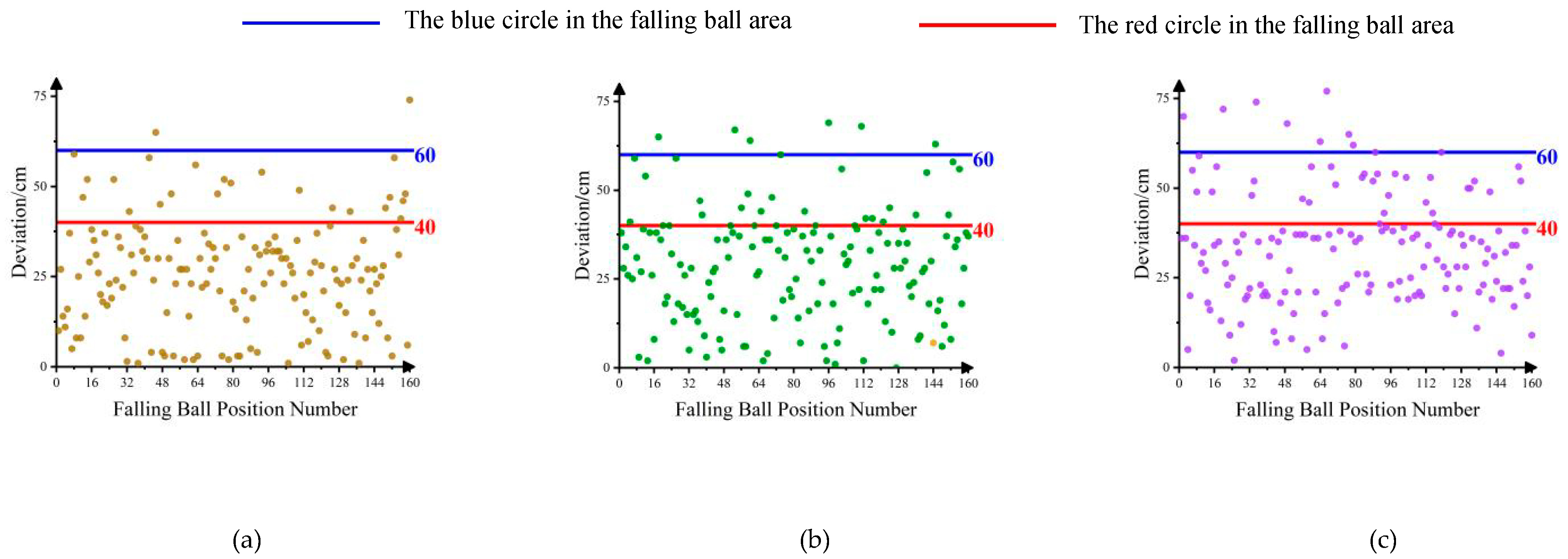
The experimental tests for the proposed badminton serving device focus on two main aspects: accuracy in recognizing posture actions and the device’s performance in ball delivery. Conducted 300 trials for each posture recognition test, achieving a consistently high posture recognition accuracy exceeding 98%. Conducted 160 launches of each ball type for evaluation and over 150 hits within the drop zone for all three tested ball types. In forthcoming endeavors, our focus will be on refining the badminton serving device through practical usage, which entails upgrades such as replacing the execution module drive motor and enhancing posture recognition methods. These enhancements are poised to elevate the device’s performance and user experience to new heights.


