Abstract
Excessive pressure drop within the internal flow channel of the water hydraulic throttle valve will generate severe noise. In order to reduce the noise of the throttle valve, in this paper, the model of the throttle valve was established, and the flow characteristics and acoustic characteristics of the valve were simulated. The simulation results showed that the parameters of the throat structure, such as the half angle, throat inlet angle and throat length, have a significant effect on the noise of the valve. Then, the three main structural parameters were used as optimization variables, and radial basis function (RBF) neural networks and multi-island genetic algorithms (MIGA) were used to reduce the noise of the valve. The approximate model of the relationship between the structural parameters of the valve and noise was established by RBF neural networks, and MIGA was used to optimize the approximate model. Finally, the optimal valve model was established based on the obtained optimal parameters, and its noise was analyzed through simulation and experiment. The research results indicated that the optimization method, which combines RBF Neural Network and MIGA, can effectively reduce the noise of hydraulic throttle valves.
1. Introduction
With the development of hydraulic throttle valves towards high-pressure and high-flow conditions, there is a large pressure gradient and velocity gradient in the internal flow channel of the water hydraulic throttle valve under high-pressure and high-flow conditions, which will generate unstable fluid and severe noise, seriously affecting the working performance and environment of the throttle valve. Therefore, it is of great significance to study the noise control method of throttle valves.
In order to reduce the noise of throttle valves, much work has been carried out by researchers. The noise of the throttle valve is closely related to its operating conditions. Zhang et al. [1] studied the flow-induced noise mechanism of an electronic expansion valve and found out that the flow velocity and pressure drop of fluid would affect the noise of the throttle valve. Shi et al. [2] studied the effect of cavitation on the noise of water hydraulic throttle valves and proposed a throttle valve structure to suppress cavitation noise. Beanad et al. [3] numerically simulated the noise generated by a throttle valve under gas-liquid two-phase flow conditions, and the locations of noise and vortex generation of the valve were obtained. Kim et al. [4] pointed out that the flow pattern of the flow field has a great influence on the noise of the throttle valve. In addition to the influence of working conditions on the noise of the throttle valve, the internal flow channel structure of the throttle valve will also affect its noise. Qin et al. [5] experimentally researched the vibration and noise of throttle valves with different structures and pointed out that multi-stage throttle structures can effectively reduce throttle valve noise. Zhou et al. [6] summarized the cavitation distribution law of the cone valve with different structures at different openings. Li et al. [7] found that the shape and structural parameters of the flow channel inside the valve have a certain functional correlation with pressure drop and Mach number through experiments and numerical analysis, and the research results provide a reference for noise control of throttle valves. A large amount of relevant literature indicates that changing the internal flow channel structure can effectively change the fluid flow state in the valve, which can achieve the goal of controlling the valve’s noise. Therefore, in order to reduce the noise of the throttle valve, most studies mainly focus on changing the internal flow channel structure of the throttle valve through simulation and experiment. However, the traditional method of noise reduction by changing the throttle channel structure relies on engineering experience, and it has a high degree of randomness. With the development of science and technology, in order to effectively control the noise of the valve, intelligent algorithms have been introduced to optimize the noise of hydraulic throttle valves [8]. Gan et al. [9] used RBF neural network response surface and adaptive NSGA-II algorithm to optimize the structure of multi-stage orifice plates; the research results showed that the proposed method can effectively reduce the noise of multi-stage orifice plates. Wang et al. [10] used a multi-objective genetic algorithm to optimize the design of pressure drilling throttle valves, and the research results found that the optimized structure can effectively improve the erosion of the throttle valve. Li et al. [11] optimized the structural parameters of the spool of the pilot control valve based on the CFD method and orthogonal test method so as to improve the stability of the valve control system. In recent years, the application of intelligent algorithms, such as neural networks and genetic algorithms in optimization design, has effectively improved the performance of industrial products [12,13]. Compared with the traditional noise reduction methods of throttle valves, the global search ability of an intelligent algorithm can effectively avoid the randomness of engineering experience, and it has strong adaptability and flexibility [14,15]. Therefore, intelligent optimization algorithms have become an effective tool for the noise reduction design of throttle valves.
In this paper, fluid dynamics theory and intelligent optimization algorithms were used to optimize the structural parameters of throttle valves. A noise reduction optimization method for the throttle valve, which is based on the RBF neural network and MIGA, is conducted. The RBF neural network is applied to establish an approximate model of the important influencing parameters of the valve core, and the MIGA is utilized to identify the optimal parameter combination. This study provides a new idea for the structural optimization and noise reduction of throttle valves.
2. Simulation
2.1. Theory
The flow and noise of the throttle valve were simulated, which is based on the three fundamental control equation theories of fluid mechanics [16].
The mass conservation equation.
where is the density of the fluid, t is time, is the velocity vector, u, v, and w are the components of the velocity vector in the directions of x, y, and z, respectively.
The momentum conservation equation.
where is the pressure on the fluid microelement; , and are the components of viscous stress in the x, y, and z directions, respectively; , and are the forces in the x, y, and z directions, respectively.
The energy conservation equation.
where is the specific heat at constant pressure, T is the temperature, k is the heat transfer coefficient of the fluid, is the viscous dissipation.
The broadband noise model is adopted to simulate the noise of the throttle valve, and The sound power is defined as follows [17].
where is the sound power, is the density of the medium, and l are the flow rate and time, respectively, is the sound speed, and is a constant.
where k is the turbulent kinetic energy, is the dissipation rate, and is a constant, = 0.1.
where is the sound power level, is the reference sound power, and the general value is 10−12 W.
It is helpful to analyze the flow field characteristics of throttle valves by Reynolds number Re.
where v, ρ, μ are the flow velocity, density, and dynamic viscosity of the fluid, respectively, and d is the diameter of the pipeline.
2.2. Throttle Model
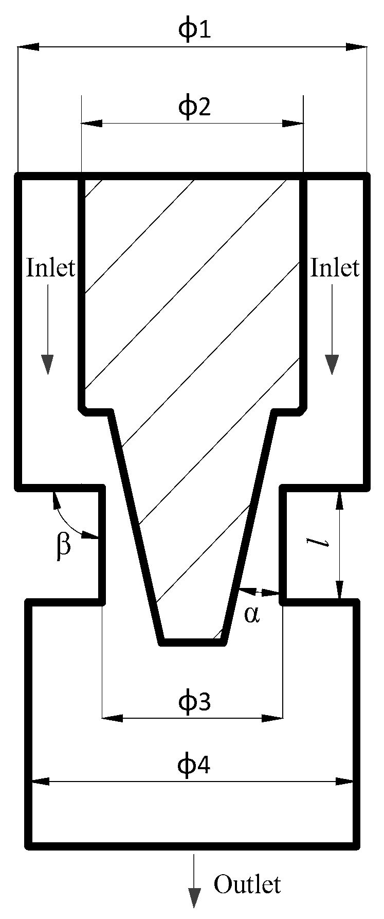
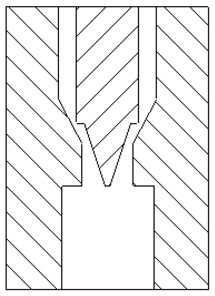
The structure of the throttle valve is shown in Figure 1, and its main structural parameters are shown in Table 1.
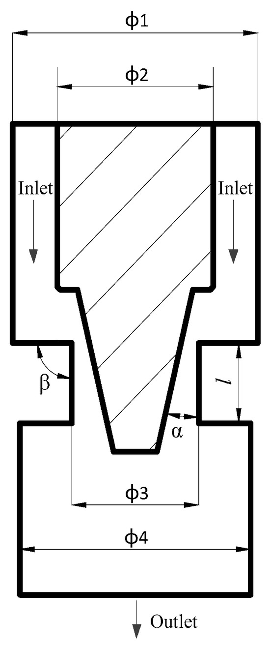
Figure 1.
Structure of the throttle valve.

Table 1.
The main parameters of the throttle valve.
Due to the axisymmetric structure of the valve core and internal flow channel, 2D simulation was used in this study. The ANSYS Mesh 18.0 software is used to generate the mesh of the throttle valve model. In order to improve computational accuracy, the mesh of the valve throat position is encrypted, as shown in Figure 2. Figure 2b is the enlarged image of the encrypted grid shown in red circle in Figure 2a.
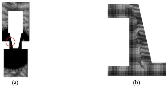
Figure 2.
Mesh of the throttle valve: (a) The mesh of the throttle valve; (b) mesh local magnification.
The meshing method in this study is based on the grid independence test of the flow field and sound field calculation results, as shown in Table 2. The independence of the mesh was verified through five different mesh calculation models. It is observed that the flow becomes stable when the number of grids exceeds 26,957. Therefore, to ensure both accuracy and efficiency in simulation calculations, the number of two-dimensional meshes selected in this study is 26,957, and the minimum grid area is 1.13 × 10⁻⁵ mm2, the maximum grid area is 3.93 × 10⁻⁴ mm2, the number of nodes is 27,563.
Table 2.
The results of mesh independence verification.
The non-equilibrium wall function was used in this study. The value of y+ is about 5 in the local encryption part, and the y+ value is about 15 in other parts.
2.3. Simulation of the Throttle Valve
The flow characteristics of the throttle valve are simulated. Steady-state Realizable turbulence model and Mixture two-phase flow model are used in the simulation. The non-equilibrium wall function, which requires less mesh quality and has higher precision, is used for the wall surface function. The boundary conditions are set as follows: the pressure of the inlet is the rated pressure of 2.5 MPa, and the pressure of the outlet is 0.7 MPa. The fluid domain condition is set as an R410 two-phase parameter. Under the pressure condition of 2.5 MPa, the liquid phase density is 967.5 kg/m3, the dynamic viscosity is 9.72 × 10⁻⁵ kg/m·s, the saturated gas phase density is 105.67 kg/m3, and the dynamic viscosity is 1.4 × 10⁻⁵ kg/m·s. The high-precision coupled solver is selected as the solution method, and the residual is set as 10−5.
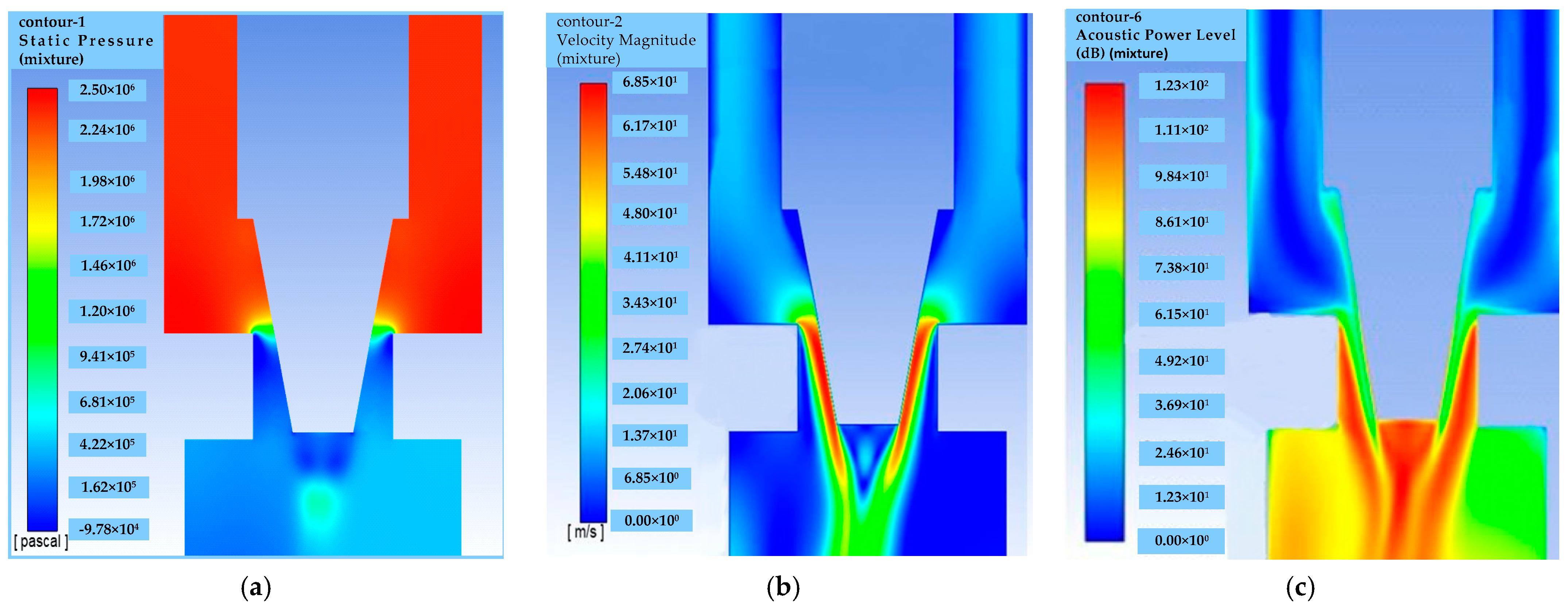
The simulation result diagram of the throttle valve is shown in Figure 3. It can be seen that the pressure at the valve inlet is high while the velocity is low. When the fluid flows through the throat of the valve spool, the fluid velocity increases rapidly, and the pressure decreases sharply. In addition, it can be found from Figure 3b that the velocity change gradient on the wall of the valve spool is significantly greater than that on the wall of the valve body.

Figure 3.
The simulation result diagram of the throttle valve: (a) the pressure cloud map; (b) the velocity cloud map; (c) the broadband noise sound field.
Figure 3c is the broadband noise of the throttle valve. From Figure 3c, it can be seen that the high noise levels are mainly concentrated in the area near the throttle throat. Therefore, the parameters of the throat structure, such as the half angle, throat inlet angle and throat length, can significantly affect the noise of the throttle valve.
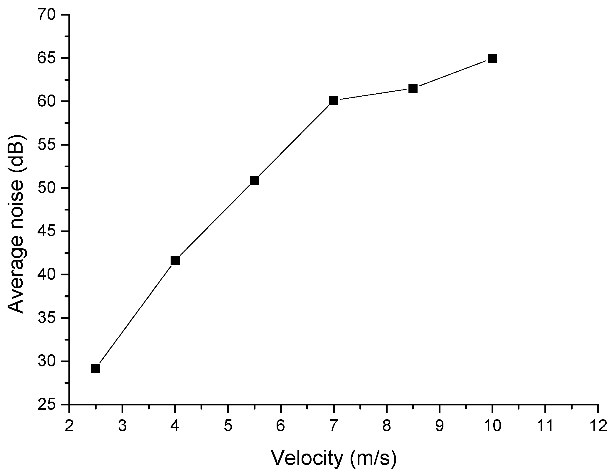
In order to study the effect of fluid velocity on the throttle valve’s noise, the noise of the water hydraulic throttle valve is simulated at the fluid velocity of 2.5 m/s, 4.0 m/s, 5.5 m/s, 7.0 m/s, 8.5 m/s, and 10.0 m/s, and the measuring point at a distance of 1.0 m on the upper side of the throttle valve was taken as the noise monitoring point. The simulation results are shown in Table 3. As shown in Figure 4, there is the simulation noise of the throttle valve. It can be seen from Figure 4 that the noise of the throttle valve is positively correlated with the velocity, and the noise increases with the velocity. When the velocity is less than 7.5 m/s, the noise increase is more obvious, and when the flow rate is greater than 7.5 m/s, the noise increase trend slows down.
Table 3.
The simulation results of the throttle valve’s noise.

Figure 4.
The simulation noise of the throttle valve.
3. Optimization of the Throttle Valve
3.1. Optimization Process
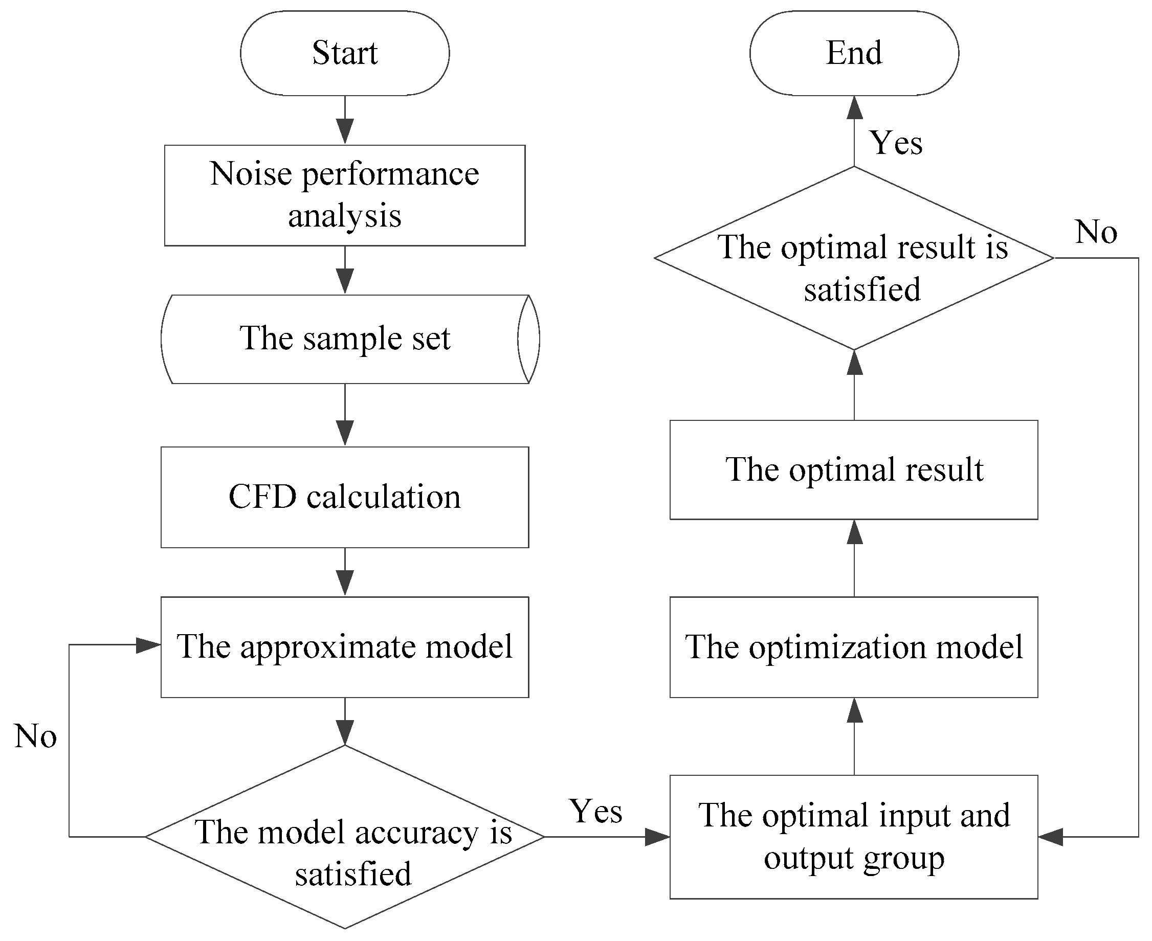
The overall optimization process of the water hydraulic throttle valve is detailed in Figure 5. The optimization process is as follows:
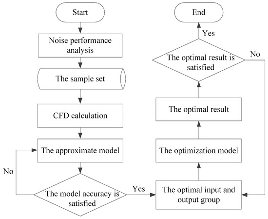
Figure 5.
The overall optimization process of the water hydraulic throttle valve.
- (1)
- According to the structural parameters of the throttle valve, the finite element model of the throttle valve is established, and the noise characteristics of the throttle valve are analyzed. The optimization parameters, constraints and optimization objectives of the throttle valve are determined according to the analysis results;
- (2)
- The optimal Latin hypercube design method is used to design the input sample set of the optimization design based on the optimization parameters and their constraints of the throttle valve, and the sample set of throttle valve optimization is obtained;
- (3)
- The finite element model of the throttle valve is changed according to the input parameters of the sample set, and the corresponding output noise value is calculated by the CFD (Computational Fluid Dynamics) software;
- (4)
- In order to express the complex coupling relationship between structural parameters and the noise of the throttle valve, an approximate model needs to be established to express the relationship between structure parameters and noise of the throttle valve, and the approximate model is established by the RBF neural network. When the accuracy does not meet the requirement, the calculation parameters will be reset, and the approximation model will be established again until the accuracy meets the requirements;
- (5)
- MIGA is used to obtain the global optimal parameter combination. The optimization model is established by the optimal parameter;
- (6)
- The optimization model of the throttle valve is simulated by CFD software, and the optimal result is calculated when the optimized result is within the allowable error range. The optimization process ends; otherwise, the optimization starts again until the accuracy meets the requirements.
3.2. Design of Sample Data
From the analysis of Section 2, it can be seen that the main parameters that affect the working performance of the throttle valve are the half-cone angle, the throat length and the throat inlet angle. In order to ensure the sealing performance of the throttle valve core and valve seat, the constraint ranges of these three parameters as shown in Table 4.
Table 4.
The constraint settings.
In order to establish an approximate model accurately, appropriate sample points should be selected within the constraints of the throttle valve’s parameters. Therefore, the optimal Latin hypercube method is selected to generate sample points. Compared with other experimental design methods, this method has more effective filling and mapping performance, and it can fit the high-order nonlinear relationship [18]. According to the design parameter range in Table 4, 40 groups of sample data are designed by using the optimal Latin hypercube method, as shown in Table 5.
Table 5.
The sample points of throttle valve parameters.
3.3. Approximate Model
The approximate model expresses the relationship between the input variable and the response variable of the mathematical model [19]. There is a complex coupling relationship between the half-cone angle, throat length, throat inlet angle and the noise of the throttle valve, and it cannot be described by a specific mathematical model. Therefore, it is necessary to establish an approximate model to express the relationship between the parameters and the noise of the throttle valve.
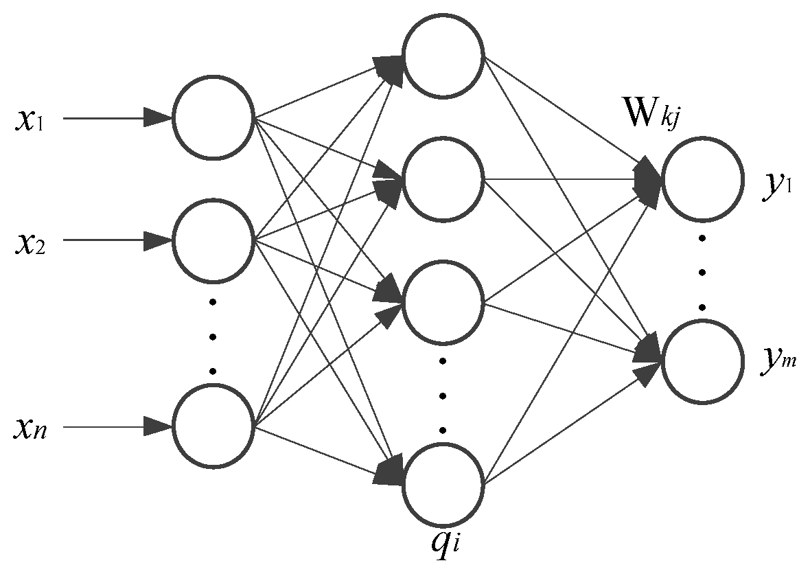
RBF neural network approximation is a kind of neural network that adopts a radial element hidden layer and linear element output layer [20], and it has a strong ability to approximate complex nonlinear functions and fast learning speed [21,22]. Therefore, the RBF neural network method is used to establish an approximate model. The working principle of the RBF neural network is shown in Figure 6.

Figure 6.
The working principle of the RBF neural network where is the input, is the hidden layer node, is the direction of output, and is the output.
The parameter settings for the RBF neural network are as follows: the smoothing filter is set to 0.045, the type of basis function is set to elliptical, and the maximum iterations to fit is set to 1600.
The complex relationship between the inputs and outputs of the approximate model is described as follows:
where y(x) is the actual value, is the approximate value, and is the error between y(x) and .
The value of average relative error is the fitting accuracy standard for judging the approximate model. Its specific value is detailed in Table 6; the average relative error of the fitted output is less than 0.2.
Table 6.
Average relative error analysis.
3.4. Optimization of MIGA
In order to obtain the global optimal parameter group, the MIGA is used to optimize the approximate model of the water hydraulic throttle valve’s parameters. A genetic algorithm is a global optimization algorithm developed by simulating the biological genetic and evolutionary processes in nature [23]. MIGA is an improved intelligent algorithm of genetic algorithm. MIGA has a strong global optimization ability and higher computational efficiency [24]. The main feature of MIGA is that a large population is divided into several subpopulations, namely “islands”, and the subpopulations on each “island” are optimized by a genetic algorithm. Therefore, the MIGA will conduct population individual exchange between “islands” and “islands” [25,26]. The main process of MIGA is shown in Figure 7.
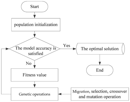
Figure 7.
The process of MIGA.
The main processes of MIGA are as follows: Firstly, the group is initialized. Secondly, the fitness value is calculated. Then, the next generation of individuals is selected according to the rules of fitness value. Finally, the genetic operations such as migration, selection, crossover and mutation are performed respectively. If the stop condition is not met, the optimization continues to calculate the fitness value. Otherwise, the optimal solution will be output.
The parameter settings of the MIGA in this optimization are shown in Table 7.
Table 7.
The parameters of MIGA.
3.5. Optimization Model
The optimization mathematical model of the throttle valve is as follows:
where x is the design variable and is the objective function.
The constraint conditions for the throttle valve throat are as follows:
In order to effectively reduce the noise of water hydraulic throttle valves, the optimization objectives of minimizing weighted average noise and minimizing weighted maximum noise are adopted.
3.6. Optimization Results
In order to verify the effectiveness of the optimization method, the optimization model is established based on the optimized parameters, as shown in Figure 8, and the simulation calculation of the optimization model is carried out. The broadband noise of the optimization valve is shown in Figure 9. The noise reduction of the valve chamber is obvious, and the average noise reduction effect is significant.
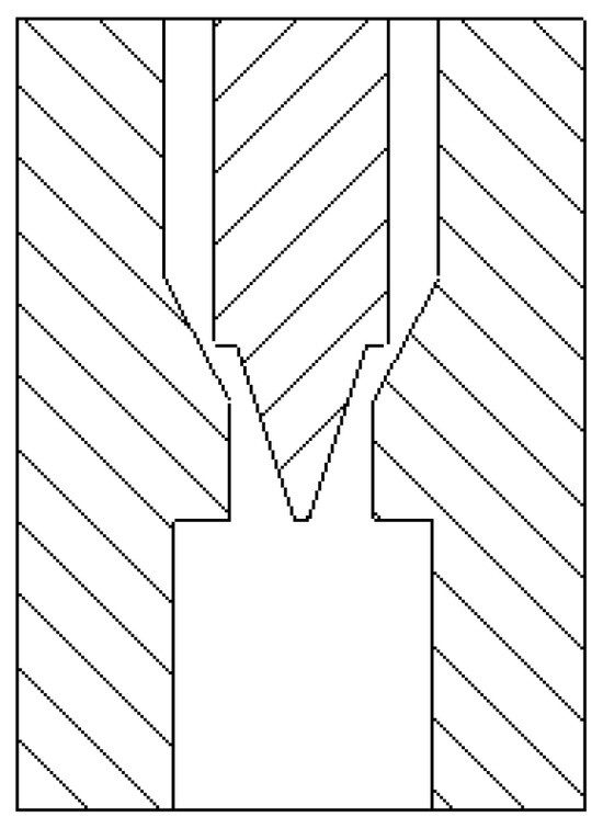
Figure 8.
The optimized model of the throttle valve.
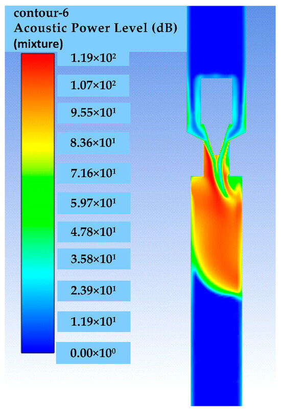
Figure 9.
The broadband noise sound field of the optimized throttle valve.
The main parameters of the valve spool and calculation results are shown in Table 8. The relative error of the weighted average noise is 2.841%, the relative error of the weighted maximum noise is 0.161%, and the reliability is high. The average noise of the optimized valve is reduced by 23.846 dB, and the maximum noise is reduced by 5.092 dB. Both the average noise and the maximum noise are considered, and the optimal parameters are finally optimized as follows: the half-cone angle is 18.431°, the throat inlet angle is 61.993°, and the throat length is 3.078 mm.
Table 8.
Comparison of optimization results.
4. Experiment
4.1. Experimental Principle
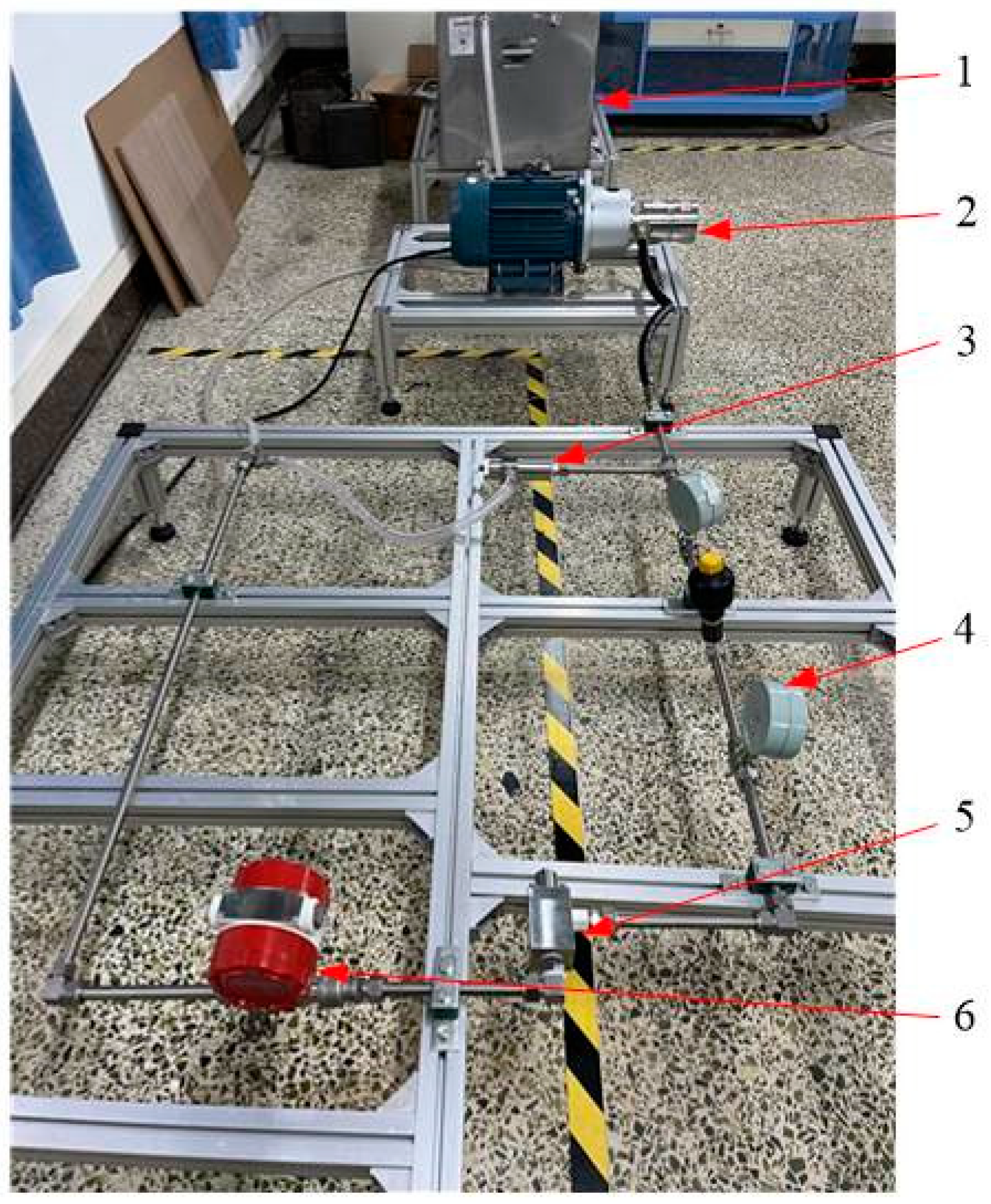
The experimental principle of throttle valve noise is shown in Figure 10, and its experimental platform is shown in Figure 11. The experimental system mainly consists of a water tank, motor, piston pump, pressure gauge, relief valve, throttle valve, and flow meter. The speed of the piston pump is controlled by a frequency converter to adjust the fluid flow rate. The working pressure of the pipeline can be read by a pressure gauge. The opening of the valve core can be adjusted to regulate the velocity of the pipeline. The velocity of the pipeline can be displayed by a flow meter.
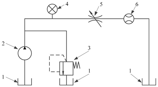
Figure 10.
Experimental principal diagram of the throttle valve noise testing system. 1—water tank, 2—piston pump, 3—relief valve, 4—pressure gauge, 5—throttle valve, 6—flow meter.

Figure 11.
The experimental platform of the throttle valve noise testing system. 1—water tank, 2—piston pump, 3—relief valve, 4—pressure gauge, 5—throttle valve, 6—flow meter.
The main parameters of the experimental system are shown in Table 9.
Table 9.
The main equipment parameters of the experimental bench.
4.2. Experimental Object
As shown in Table 6, The final optimized throttle valve parameters through the intelligent optimization algorithm are a half-cone angle of 18.431°, a throat inlet angle of 61.993°, and a throat length of 3.078 mm. The manufacturing accuracy and errors are considered, and the main size of the optimized physical throttle valve is determined to be a half-cone angle of 18.400°, a throat inlet angle of 62.000°, and a throat length of 3.100 mm.
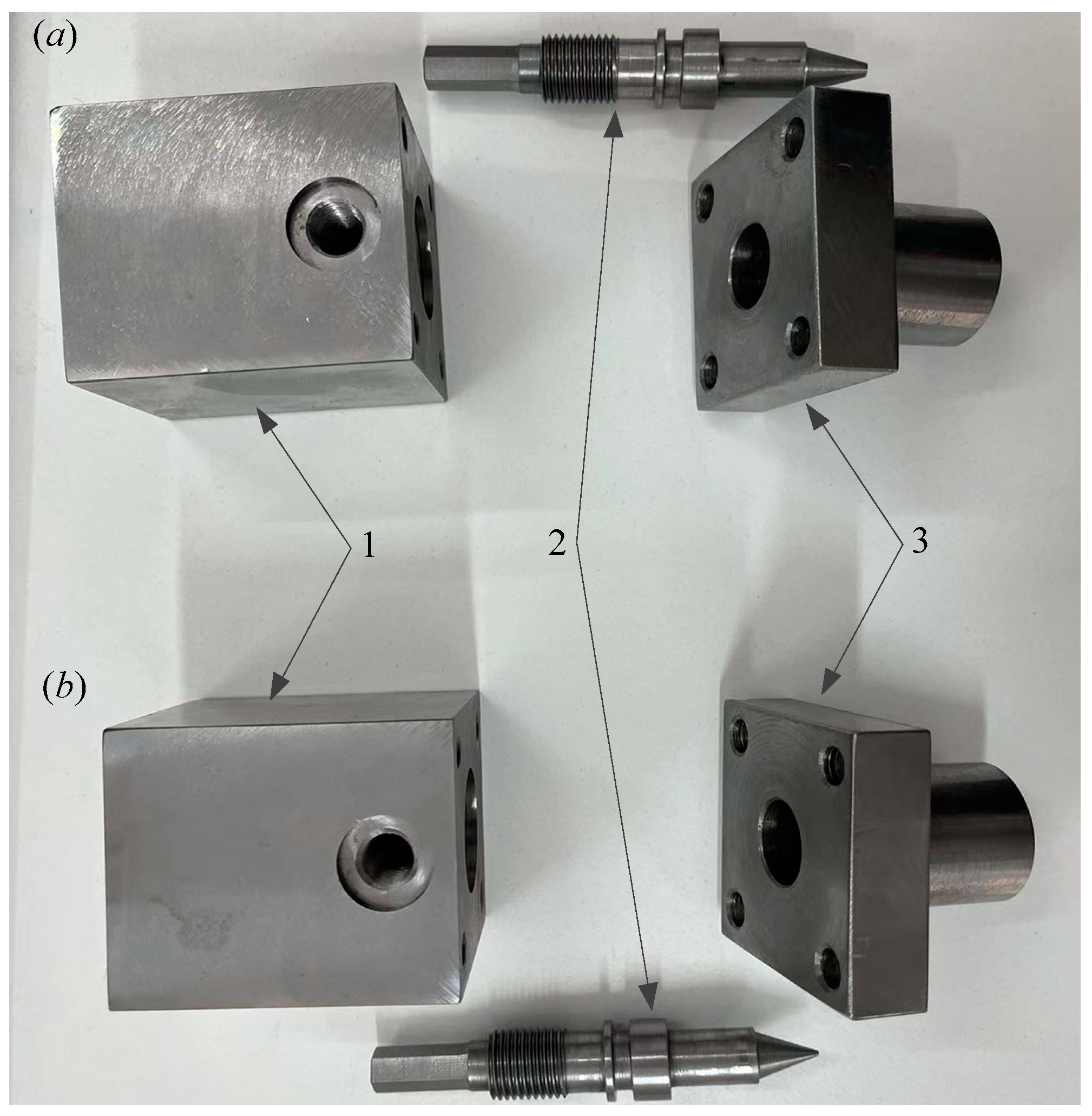
The structure of the original and optimized valves is shown in Figure 12. This throttle valve mainly consists of three parts: valve body, valve core, and end cover. The valve core and valve body are connected by the valve core threaded sleeve, and the sealing ring is used to ensure the sealing of the throttle valve. The cover plate is connected to the valve core through a threaded pair, and the throttle valve opening is adjusted by moving the valve core. As shown in Figure 13, there are the original and optimized water hydraulic throttle valves that have been manufactured.
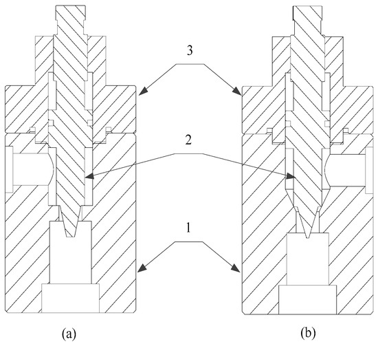
Figure 12.
The original and optimized water hydraulic throttle valve structure: (a) original; (b) optimized. 1—valve body, 2—valve core, 3—end cover.
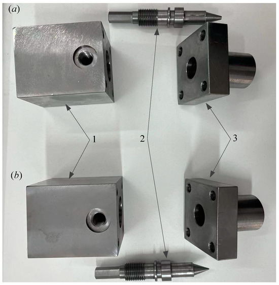
Figure 13.
The original and optimized water hydraulic throttle valves that have been manufactured: (a) original; (b) optimized. 1—valve body, 2—valve core, 3—end cover.
4.3. Experimental Procedure
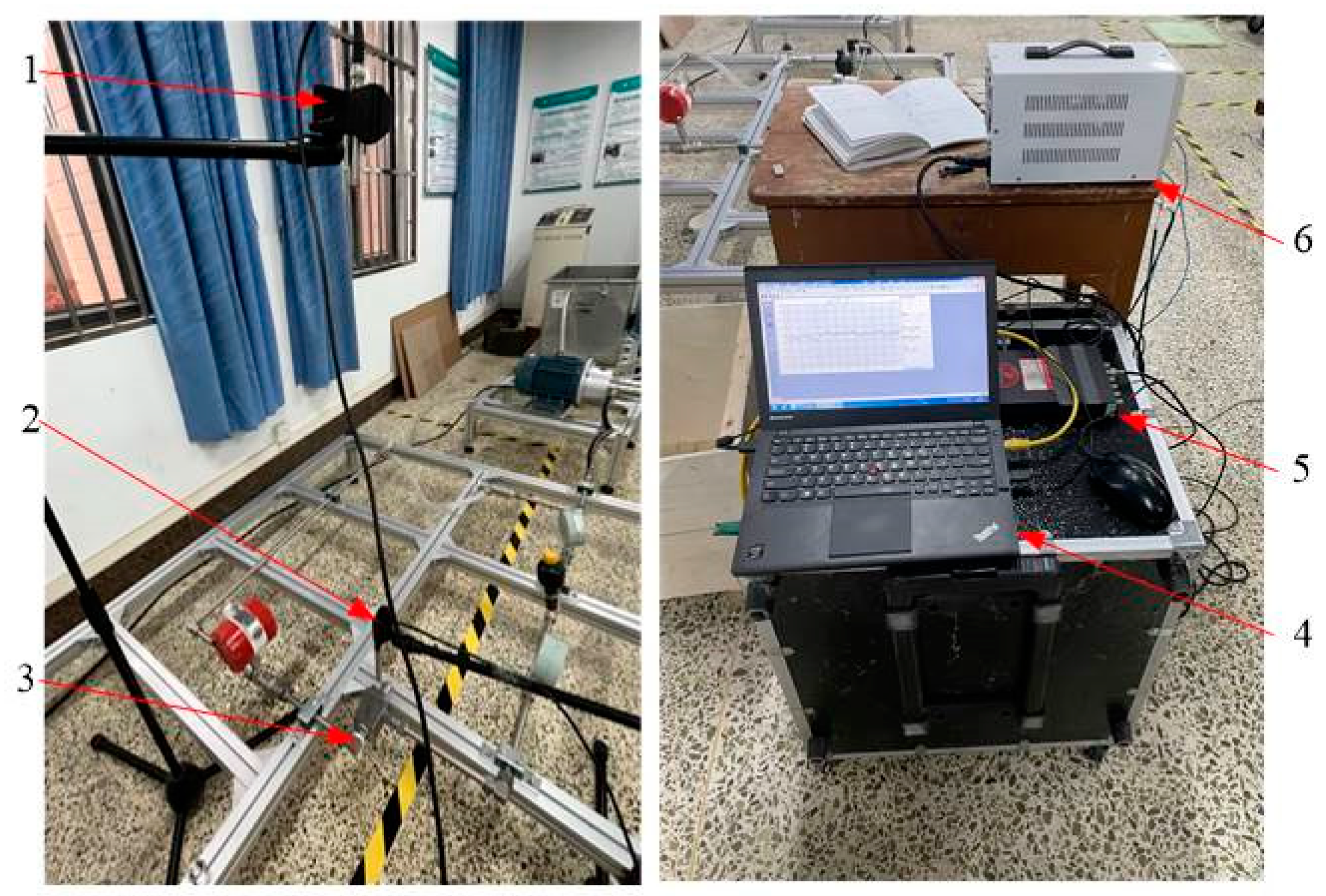
The parameters of the noise experimental equipment are shown in Table 10, and the throttle valve noise experimental bench is shown in Figure 14.
Table 10.
The parameters of the noise experimental equipment.

Figure 14.
The water hydraulic throttle valve noise experimental bench. 1—microphone 1, 2—microphone 2, 3—water hydraulic throttle valve, 4—the acquisition system, 5—computer, 6—DC power supply.
The measurement procedures for throttle valves’ noise are as follows:
- (1)
- According to noise measurement standards GB/T 17213.14-2018 [27], microphone measurement points are arranged. In order to reduce the interference of error to measurement results, two different noise measurement points are selected for measurement: the measuring point at a distance of 0.1 m from the valve is defined as measuring point 1, and the measuring point at a distance of 1.0 m from the valve is defined as the measuring point 2. The noise of the original throttle valve and the optimized throttle valve at measuring point 1 and point 2 were measured separately;
- (2)
- In order to avoid interference from environmental noise and the hydraulic system, the background noise of the experimental environment is measured first;
- (3)
- Then, a straight pipe is used instead of the valve; the length of the straight pipe is the same as that of the throttle valve, and the noise of the hydraulic system without a valve is measured;
- (4)
- The outlet flow of the throttle valve can be adjusted by the opening of the throttle valve and relief valve. The velocity of the throttle valve’s outlet can be calculated based on parameters such as pipe diameter and flow, and the noise of the water hydraulic throttle valve is measured at the velocity of 2.5 m/s, 4.0 m/s, 5.5 m/s, 7.0 m/s, 8.5 m/s, and 10.0 m/s;
- (5)
- The noise on the right side and the upper side of the throttle valve were measured separately;
- (6)
- The effectiveness of the optimization method is verified by comparing the noise of the original throttle valve and the optimized throttle valve under the same experimental conditions;
- (7)
- All microphones were connected to the same acquisition system (LAN-XI Type: 3050-B-060 6ch, Brüel & Kjær), and the data analysis was conducted in PULSE LabShop 14.1 (Brüel & Kjær) and MATLAB 7.0 software;
- (8)
- The frequency band of interest was set from 0 Hz up to 5000 Hz, the sampling rate of the system was 12,800 Hz, and the sampling time was 120 s;
- (9)
- In order to compare the measurement results conveniently, the measured noise adopts the sound pressure level measured by the A-weighted method.
4.4. Experimental Results
The background noise during the measurement is 28.44 dB. As shown in Table 9 and Table 10, the throttle valve’s noise in all operating conditions is greater than 70 dB. The working noise of the throttle valve is higher than the background noise by more than 30 dB, so the influence of background noise on the noise measurement results of the throttle valve can be ignored.
In order to avoid the interference of the throttle valve on the experimental results, a straight pipe is used instead of the valve, and the noise of the hydraulic system without a valve is measured. Since there is no throttle valve to regulate the pressure and flow, the noise of the hydraulic system with a straight pipe can only be measured under no-load conditions. The upper side noise and right side noise of the hydraulic system at measuring point 1 are 78.63 dB and 75.40 dB, respectively. The upper side noise and right side noise of the hydraulic system at measuring point 2 are 74.60 dB and 75.31 dB, respectively.
The experimental temperature is 20 °C, the dynamic viscosity of water is 1.005 × 10⁻³ Pa * s, the density of water is 1.0 × 10³ kg/m3, and the pipeline diameter is 16 mm. The Reynolds number of different flow velocities can be calculated according to Equation (8).
As shown in Table 11 and Figure 15, there is the measured noise of the original throttle valve and the optimized throttle valve at measuring point 1.
Table 11.
The noise of the throttle valve at measuring point 1.
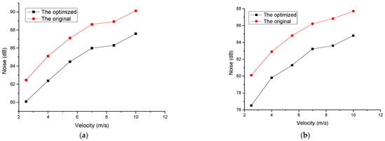
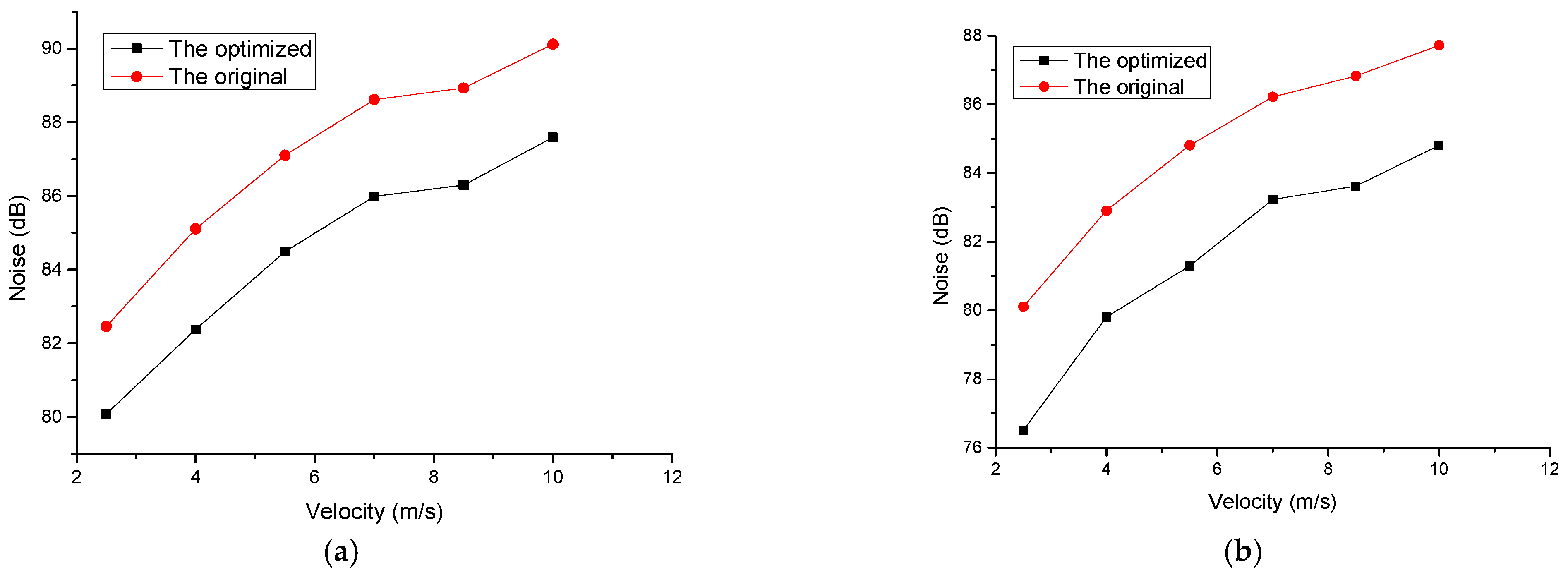
Figure 15.
The measured curves of the original throttle valve and the optimized throttle valve at measuring point 1: (a) the upper side; (b) the right side.
It can be observed that the noise variation trend of the original throttle valve and the optimized throttle valve is consistent at different velocities. Compared to the noise of the original throttle valve, the noise measured on the upper side of the optimized throttle valve has been reduced by at least 2.38 dB, and the noise measured on the right side of the optimized throttle valve has been reduced by at least 2.91 dB.
As shown in Table 12 and Figure 16, there are the measured curves of the original throttle valve and the optimized throttle valve at measuring point 2. It can be seen that compared to the original throttle valve, the noise values measured on the upper side of the optimized throttle valve have been reduced by at least 1.20 dB, and the noise values measured on the right side of the optimized throttle valve have been reduced by at least 1.33 dB, which proves the effectiveness of the optimization method.
Table 12.
The noise of the throttle valve at measuring point 2.
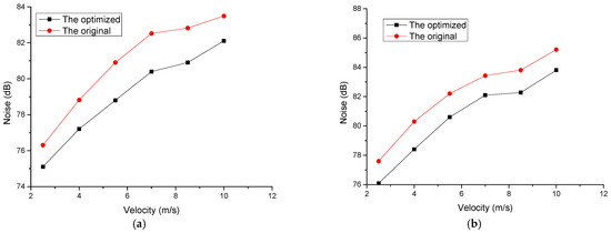
Figure 16.
The measured curves of the original throttle valve and the optimized throttle valve at measuring point 2: (a) the upper side; (b) the right side.
The experimental results show that the noise value increases with the velocity increases. There is a difference between the simulated and the experimentally measured noise value; however, the overall trend of change is basically the same, which also verifies the correctness of the simulation model.
When the throttle valve opening is the same, and the measurement conditions are the same, the trend of the noise of the original and the optimized throttle valve under different velocities is consistent. By comparing the simulation results curve in Figure 4, it can be seen that the trend of simulation noise and experimental noise is basically consistent. However, due to the presence of environmental noise and hydraulic system noise, there is a certain difference in numerical values between simulation noise and experimental noise.
5. Conclusions
In this paper, the RBF neural network and MIGA were used to optimize the structural parameters of the throttle valve. Simulation and experiment were conducted on the models of the original throttle valve and the optimized throttle valve. The results showed that the maximum and average noise of the optimized throttle valve were reduced. The original throttle valve and the optimized throttle valve were manufactured, and their noise was experimentally measured. The results of this study provide a reference for the structural design and noise optimization of throttle valves. The specific conclusions are summarized as follows:
- (1)
- The fluid and noise characteristics during the operation of the throttle valve were analyzed using numerical simulation methods. It was found that the pressure, velocity, and noise of the fluid would change dramatically when it flowed through the throat position, and the induced noise peak was mainly concentrated near the throat position, which provided a reference for the optimization of the throttle valve structure;
- (2)
- Half-cone angle, throat length and throat inlet angle are selected as the key structural parameters of the throttle valve, and the influence of structural parameters on the noise of the throttle valve is studied. The study found that the throttle valve’s noise gradually increased with the increase in the half-cone angle. As the length of the throat increases, the noise of the throttle valve changes periodically. As the angle of the throat inlet increases, the noise of the throttle valve decreases first and then increases;
- (3)
- The structure parameters and noise of the throttle valve were optimized by using the RBF neural network and MIGA, and the water hydraulic throttle valve noise experimental bench was built to measure the noise of the throttle valve. The experimental results showed that the comprehensive average noise of the optimized throttle valve decreased by 2.38 dB at measuring point 1, and the comprehensive average noise at measuring point 2 decreased by 1.20 dB, which verified the effectiveness of the optimization method.
In this optimization of the throttle valve, three main structural parameters that affect the noise of the throttle valve were selected. However, in order to further improve the noise reduction effect of the throttle valve, more structural parameters that affect the working performance of the valve need to be found. In addition, due to limited experimental conditions, it is impossible to avoid the influence of the noise generated by the motor and piston pump, which may cause certain errors in the experimental results. In subsequent research, it is necessary to establish a more comprehensive experimental system and adopt more rigorous experimental methods.
Author Contributions
Conceptualization, H.W. and X.L.; methodology, X.Z.; software, X.Z.; validation, X.Z., L.N. and H.W.; formal analysis, B.W.; investigation, Y.W.; resources, L.H.; data curation, L.H.; writing—original draft preparation, X.Z.; writing—review and editing, H.W.; visualization, X.Z.; supervision, X.L.; project administration, L.H.; funding acquisition, B.W. All authors have read and agreed to the published version of the manuscript.
Funding
This work was supported by the Ministry of Education University-Industry Collaborative Education Program of China [grant number 220702696273543], the Knowledge Innovation Program of Wuhan-Shugung Project [grant number 2023010201020408], the National Natural Science Foundation of China [grant number 52375260] and the National Natural Science Foundation of China [grant number 51975224].
Data Availability Statement
Data is contained within the article.
Conflicts of Interest
Author Xin Zhou was employed by the company Bosch Hua Yu Steering System (Wuhan) Company. The remaining authors declare that the research was conducted in the absence of any commercial or financial relationships that could be construed as a potential conflict of interest.
References
- Zhang, L.; Wang, J.; Song, Y.; Li, J.; Wu, D.; Liu, J. Flow-induced noise mechanism and optimization design of electronic expansion valve. Vacuum 2022, 204, 111335. [Google Scholar] [CrossRef]
- Shi, W.; Cao, S.; Luo, X.; Zhang, Z.; Zhu, Y. Experimental research on the cavitation suppression in the water hydraulic throttle valve. J. Press. Vessel-Technol. ASME 2017, 139, 051302. [Google Scholar]
- Bernad, S.I.; Susan-Resiga, R. Numerical model for cavitational flow in hydraulic poppet valves. Mod. Simul. Eng. 2012, 2012, 10. [Google Scholar] [CrossRef]
- Kim, G.; Lee, J.; Park, J.; Song, S. Flow visualization and noise measurement of R410A two-phase flow near electric expansion valve for heating cycle of multi-split air-source heat pump. Appl. Therm. Eng. 2019, 157, 113712. [Google Scholar] [CrossRef]
- Qin, Z.; Cai, B.; Xiao, L. Experimental study on vibration and noise of throttle valve in water-conveying systems. In Proceedings of the 7th International Conference on Fluid Mechanics and Industrial Applications (FMIA 2023), Taiyuan, China, 27–28 May 2023. [Google Scholar]
- Zhou, X.; Liu, S.; Lu, Y.; Zhang, H.; Shao, H.; Tian, Y. Research and Analysis on Cavitation of Different Structures of Cone Valve Ports in Pure Water. In Proceedings of the International Conference on Advanced Manufacturing Technology and Electronic Information, Zhuhai, China, 5–7 November 2021. [Google Scholar]
- Li, N.; Wan, S.; Du, W.; Zhang, S.; Luo, L. Effects of the geometrical features of flow paths on the flow behaviour of a multi-stage labyrinth pressure reducing valve throttling components. Energy 2024, 296, 130962. [Google Scholar] [CrossRef]
- Tang, T.; Yang, G.; Zhang, D.; Lei, L.; Li, B.; Gao, L. A hydrodynamic prediction model of throttle orifice plate using space filling and adaptive sampling method. Struct. Multidisc. Optim. 2020, 62, 1563–1578. [Google Scholar] [CrossRef]
- Gan, R.; Li, B.; Tang, T.; Liu, S.; Chu, J.; Yang, G. Noise optimization of multi-stage orifice plates based on RBF neural network response surface and adaptive NSGA-II. Ann. Nucl. Energy 2022, 178, 109372. [Google Scholar] [CrossRef]
- Wang, G.R.; Chu, F.; Tao, S.Y.; Jiang, L.; Zhu, H. Optimization design for throttle valve of managed pressure drilling based on CFD erosion simulation and response surface methodology. Wear 2015, 338, 114–121. [Google Scholar] [CrossRef]
- Li, S.; Deng, G.; Hu, Y.; Yu, M.; Ma, T. Optimization of structural parameters of pilot-operated control valve based on CFD and orthogonal method. Results Eng. 2024, 21, 101914. [Google Scholar] [CrossRef]
- Yang, G.; Yao, J. Multilayer neurocontrol of high-order uncertain nonlinear systems with active disturbance rejection. Int. J. Robust Nonlin. Control. 2024, 34, 2972–2987. [Google Scholar] [CrossRef]
- Yang, G.; Wang, H.; Yao, J.; Zou, X. Multilayer neurocontrol of servo electromechanical systems with disturbance compensation. Appl. Soft Comput. 2024, 151, 111043. [Google Scholar] [CrossRef]
- Tang, T.; Gao, L.; Li, B.; Liao, L.; Xi, Y.; Yang, G. Cavitation optimization of a throttle orifice plate based on three-dimensional genetic algorithm and topology optimization. Struct. Multidisc. Optim. 2019, 60, 1227–1244. [Google Scholar] [CrossRef]
- Chen, F.; Jin, Z. Fluid dynamics analysis and optimized throttling design of L-shaped multi-stage high pressure reducing valve. Flow Meas. Instrum. 2023, 89, 102296. [Google Scholar] [CrossRef]
- Einkemmer, L.; Joseph, I. A mass, momentum, and energy conservative dynamical low-rank scheme for the Vlasov equation. J. Comput. Phys. 2021, 443, 110495. [Google Scholar] [CrossRef]
- Zhou, Y. Turbulence theories and statistical closure approaches. Phys. Rep. 2021, 935, 1–117. [Google Scholar]
- Li, G.; Yang, J.; Wu, Z.; Zhang, W.; Okolo, P.; Zhang, D. A sequential optimal Latin hypercube design method using an efficient recursive permutation evolution algorithm. Eng. Optimiz. 2022, 56, 179–198. [Google Scholar] [CrossRef]
- Wang, G.; Yao, S.; Pei, M.; Xu, J. A Three-Dimensional Subspace Algorithm Based on the Symmetry of the Approximation Model and WYL Conjugate Gradient Method. Symmetry 2023, 15, 1207. [Google Scholar] [CrossRef]
- Hao, J.; Suo, S.; Yang, Y.; Wang, Y.; Wang, W.; Chen, X. Optimization of torque ripples in an interior permanent magnet synchronous motor based on the orthogonal experimental method and MIGA and RBF neural networks. IEEE Access 2020, 8, 27202–27209. [Google Scholar] [CrossRef]
- Quadros, J.D.; Khan, S.A. Prediction of base pressure in a suddenly expanded flow process at supersonic Mach number regimes using ANN and CFD. J. Appl. Fluid Mech. 2020, 13, 499–511. [Google Scholar] [CrossRef]
- Qian, J.; Chen, L.; Sun, J.Q. Transient response prediction of randomly excited vibro-impact systems via RBF neural networks. J. Sound Vib. 2023, 546, 117456. [Google Scholar] [CrossRef]
- Jalali, Z.; Noorzai, E.; Heidari, S. Design and optimization of form and facade of an office building using the genetic algorithm. Sci. Technol. Built. Environ. 2020, 26, 128–140. [Google Scholar] [CrossRef]
- Zhang, K.; Ma, H.; Li, Q.; Wang, D.; Song, Q.; Wang, X. Thermodynamic analysis and optimization of variable effect absorption refrigeration system using multi-island genetic algorithm. Energy Rep. 2022, 8, 5443–5454. [Google Scholar] [CrossRef]
- Jiang, H.; Xu, M.; Yao, W. Aerodynamic shape optimization of co-flow jet airfoil using a multi-island genetic algorithm. Phys. Fluids 2022, 34, 125120. [Google Scholar] [CrossRef]
- Xu, Y.; Zhang, H.; Yang, Y.; Zhang, J.; Yang, F.; Yan, D. Optimization of energy management strategy for extended range electric vehicles using multi-island genetic algorithm. J. Energy Storage 2023, 61, 106802. [Google Scholar] [CrossRef]
- GB/T 17213.14-2018; Industrial-Process Control Valves-Part 8-2: Noise Considerations-Laboratory Measurement of Noise Generated by Hydrodynamic Flow through Control Valves. State Administration for Market Regulation: Beijing, China, 2018.


Disclaimer/Publisher’s Note: The statements, opinions and data contained in all publications are solely those of the individual author(s) and contributor(s) and not of MDPI and/or the editor(s). MDPI and/or the editor(s) disclaim responsibility for any injury to people or property resulting from any ideas, methods, instructions or products referred to in the content. |
© 2024 by the authors. Licensee MDPI, Basel, Switzerland. This article is an open access article distributed under the terms and conditions of the Creative Commons Attribution (CC BY) license (https://creativecommons.org/licenses/by/4.0/).