Article

Optimal Design of Quadcopter Chassis Using Generative Design and Lightweight Materials to Advance Precision Agriculture

1
Department of Mechanical Engineering, Thapar Institute of Engineering and Technology, Patiala 147004, India
2
Department of Electrical and Instrumentation Engineering, Thapar Institute of Engineering and Technology, Patiala 147004, India
3
Department of Industrial Design, National Institute of Design, Jorhat 785014, India
4
Department of Mechanical Engineering, National Institute of Technology, Hamirpur 177005, India
*
Author to whom correspondence should be addressed.
Machines 2024, 12(3), 187; https://doi.org/10.3390/machines12030187
Submission received: 16 February 2024 / Revised: 7 March 2024 / Accepted: 11 March 2024 / Published: 13 March 2024
(This article belongs to the Section Machine Design and Theory)

Abstract

:
This research addresses the imperative challenge of a lightweight design for an Unmanned Aerial Vehicle (UAV) chassis to enhance the thrust-to-weight and power-to-weight ratios, crucial for optimal flight performance, focused on developing an intriguing lightweight yet robust quadcopter chassis. Advanced generative design techniques, integrated with topology optimization, using Autodesk Fusion 360 software (v. 16.5. 0.2083), 3D-printing methods and lightweight materials like Polylactic Acid (P.L.A.), Acrylonitrile Butadiene Styrene (A.B.S.), and Nylon 6/6 play a significant role in achieving the desired balance between structural integrity and weight reduction. The study showcases successful outcomes, presenting quadcopter chassis designs that significantly improve structural efficiency and overall performance metrics. The findings contribute to aerial robotics and hold promise for precision agriculture applications with relevant performed simulations, emphasizing the importance of tailored design methodologies for other engineering domains. In conclusion, this research provides a foundational step toward advancing drone technology, with weight reductions of almost 50%, P/W and T/W ratios increment of 6.08% and 6.75%, respectively, at least an 11.8% increment in Factor of Safety, at least a 70% reduction in stress values and reduced manufacturing time from its comparative DJI F450 drone, demonstrating the critical role of innovative design approaches in optimizing operational efficiency for targeted applications.

1. Introduction

Unmanned Aerial Vehicles (UAVs), popularly known as drones, have revolutionized numerous industries with their unmatched versatility and efficiency [1]. These aerial vehicles are pivotal in optimizing crop management and resource utilization in precision agriculture. By capturing high-resolution imagery and multispectral data, drones facilitate precise monitoring of crop health, pest infestations, and overall field conditions [2,3]. This study delves into the intersection of advanced design methods and materials applied to the design of quadcopter drone chassis, aiming to propel advancements in precision agriculture [4]. In the context of existing research, integrating generative design principles with materials and 3D printing represents an innovative approach [5,6].
This introduction aims to contextualize the study, emphasizing its significance in pushing the boundaries of drone technology for agricultural applications. At its core, this research seeks to address gaps in current designs, paving the way for high performance and increased power-to-weight and thrust-to-weight ratios, resulting in a more efficient, cost-effective, and sustainable approach to precision agriculture. Increasing the thrust-to-weight and power-to-weight ratios in lightweight drone designs enhance performance and agility. A higher thrust-to-weight ratio leads to quicker acceleration and improved maneuverability, while a higher power-to-weight ratio facilitates faster climbs and better handling in flying conditions. These improvements result in the increased responsiveness of the drone and overall flight capabilities that can benefit flight quality and time.
The following sections will unravel the complexities of 3D-printed generative design, culminating in insights that hold promise for the evolution of intelligent agricultural practices. At the forefront of precision agriculture, the synergy between data-driven farming and advanced drone technology promises transformative outcomes. Leveraging data for precise decision-making, drones facilitate precision crop monitoring, enabling issue detection and informed decision-making [7]. This dynamic process ensures optimal crop health and feeds into an efficient resource management strategy where resources are judiciously allocated. The culmination of these practices represents a paradigm shift towards efficient farming, blending innovative techniques with data insights for heightened productivity and sustainability [8].
In the pursuit of advancing the design technology, Autodesk Fusion 360 Generative Design technology has been utilized, which allows for optimization of the parameters and provides the best possible results through topology optimization, guided by sophisticated algorithms, which emerges as a critical facet, strategically minimizing weight while maximizing structural integrity for various drone elements and their functionality, as listed in Table 1. Autodesk Fusion 360 is a cloud-based C.A.E. software (v. 16.5. 0.2083), which is easy to run and requires no such special configurations of the device to run on, as it does not use the device’s internal graphics and memory, making it versatile and usable on any operating system and environment. The current study uses a device with 4 GB RAM and 512 GB internal memory, with Intel® Core™ i5 processor (Acer Aspire 7, Acer India Private Limited, Puducherry, India.) with Windows 11 operating system, is utilized. The generative study performed on this software took around 15 to 20 min till convergence for the current design, which is variable for design type, complexity configurations and device specifications.
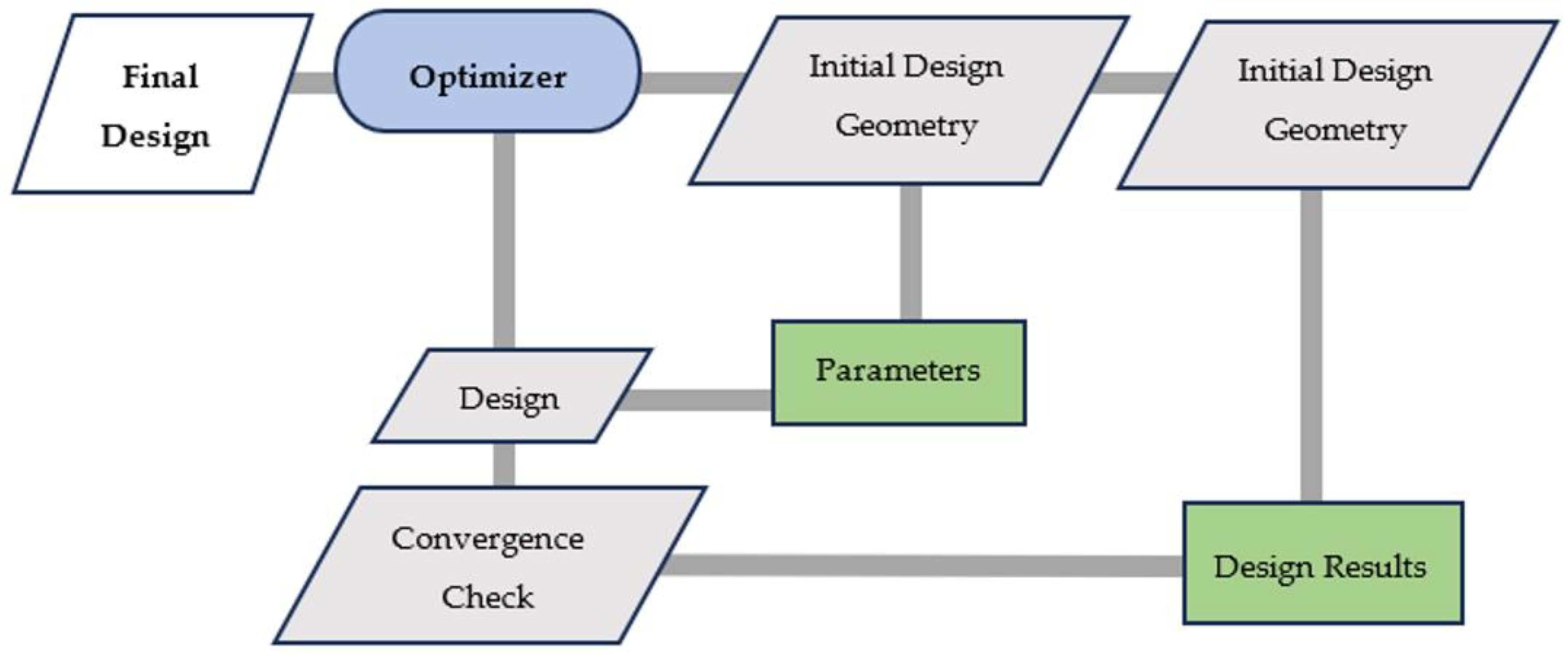
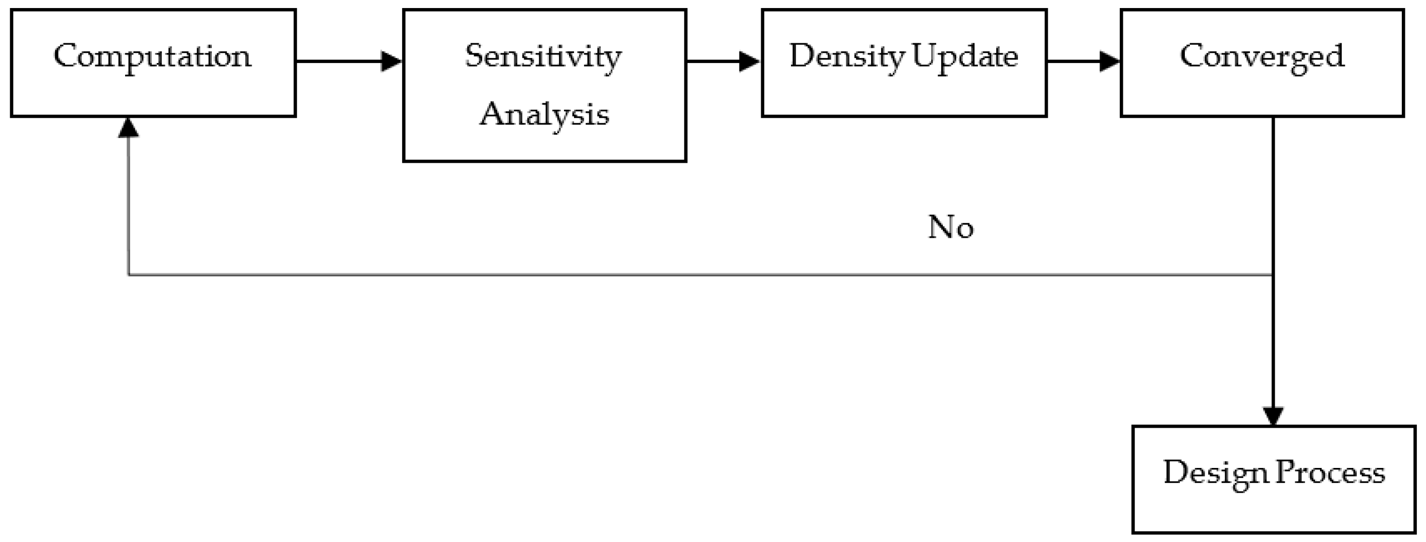
This optimization algorithm-based study of generative design enhances system performance by facilitating seamless collaboration between components [9]. Optimization plays a pivotal role in driving efficiency and innovation in complex systems. It identifies the most effective solution from various choices, considering various goals, limitations, and uncertainties. It guarantees the most efficient use of resources within engineering and design, enhancing the systems’ performance, dependability, and eco-friendliness. The integration of rapid generation and evaluation of design alternatives through algorithmic iteration provides the best outcome from optimization. Generative design, a result of multidisciplinary optimization (M.D.O.) principles, transforms conventional design methods through the use of computational algorithms to examine vast design territories. It methodically creates and appraises countless design alternatives based on set objectives, restrictions, and performance standards. The concept of M.D.O. is based on tackling intricate design issues a notch higher by engaging multiple engineering areas. It considers the communication between different subsystems, intending to discover superior solutions that improve the entire system’s function. In M.D.O., various improvement strategies are utilized, which can be split into definite and uncertain methodologies. Precise optimization techniques, like algorithms based on gradients or line-based programming, depend on accurate math layouts to reach ideal solutions effectively. Such manners of problem-solving are suitable for well-structured issues with specific limits and goals [10]. Like genetic algorithms, simulated annealing and particle swarm optimization are non-deterministic optimization techniques for dealing with complex and ill-defined problems. These methods are designed to explore the design space randomly, just like evolutionary processes or random searches do to find near-optimal solutions in the form of probabilistic models. In addition, errors must be considered during optimization procedures in realistic modeling and decision-making. For example, measurement inaccuracies, modeling assumptions, or environmental uncertainties may cause these errors. Therefore, taking into account the errors in the optimization process makes sure that the solutions obtained are robust and able to cope with practical conditions. This enhances the drone’s overall efficiency and aligns with the imperative for lightweight and robust aerial platforms in agricultural settings. Systematic integration algorithms further play a crucial role, ensuring cohesiveness among diverse drone elements. As we delve into the subsequent sections of this research, each of these components will be dissected and analyzed, shedding light on their specific contributions to the evolution of high-performance quadcopter drone chassis for precision agriculture.
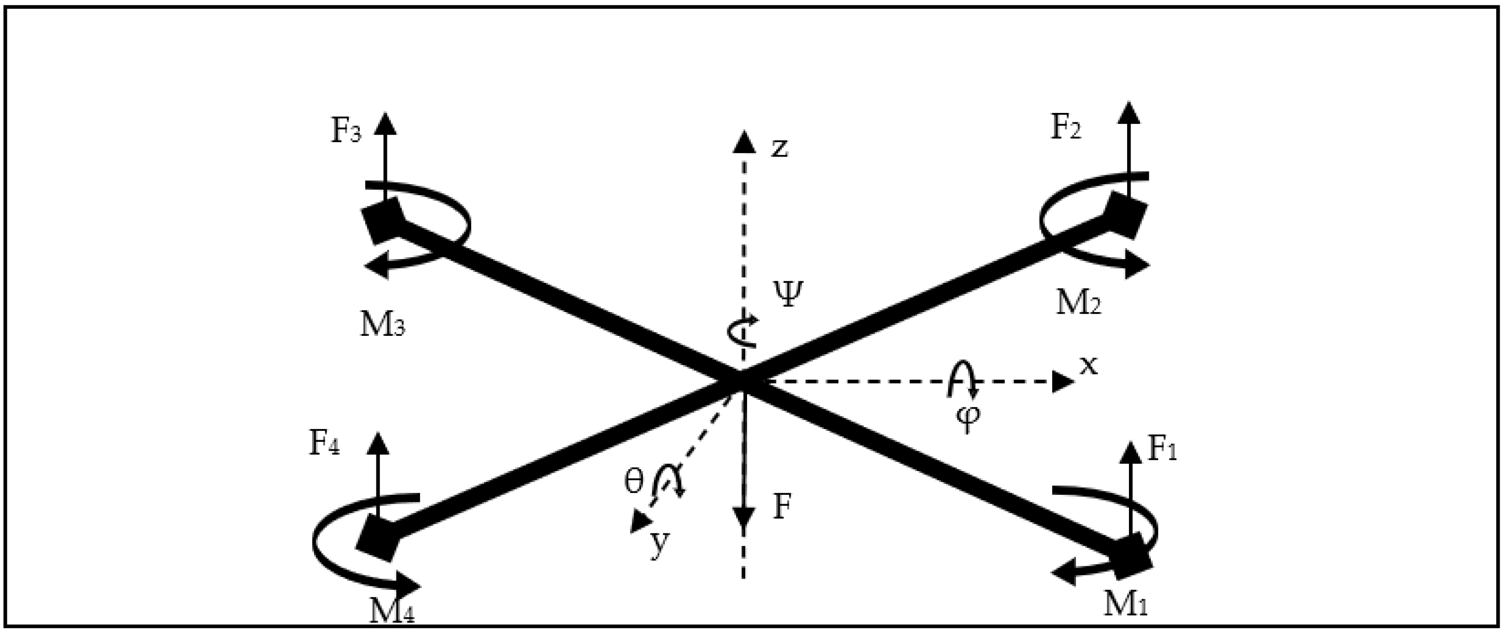
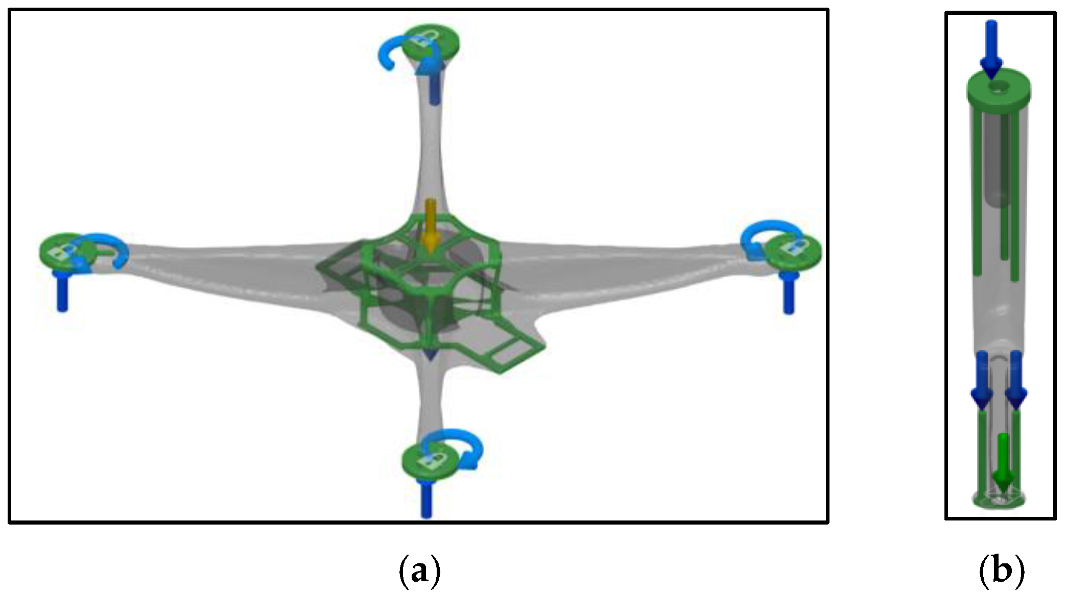
Figure 1 shows a typical quadcopter design for the specified application, including the components listed in Table 1. Pushing the boundaries of quadcopter technology, this study delves into a thorough design exploration with well-defined goals, which starts with the meticulous design of a quadcopter chassis characterized by diagonal dimensions of 500 mm and a height of 55 mm [11], with recommended landing gears of about 110 mm [12]. Prioritizing structural integrity, the chassis is engineered to accommodate a load of up to 2.5 kg (2.5 kg or 2500 g), including a 1 kg (1000 g) payload, while maintaining a minimum Factor of Safety of 1.2 [4]. Adhering to contemporary aerospace engineering principles, the chassis is designed to be lightweight without compromising robustness, optimizing both power-to-weight and thrust-to-weight ratios. These objectives underscore a commitment to precision and efficiency, ensuring the quadcopter meets the specific demands and establishes a benchmark for reliability and performance.
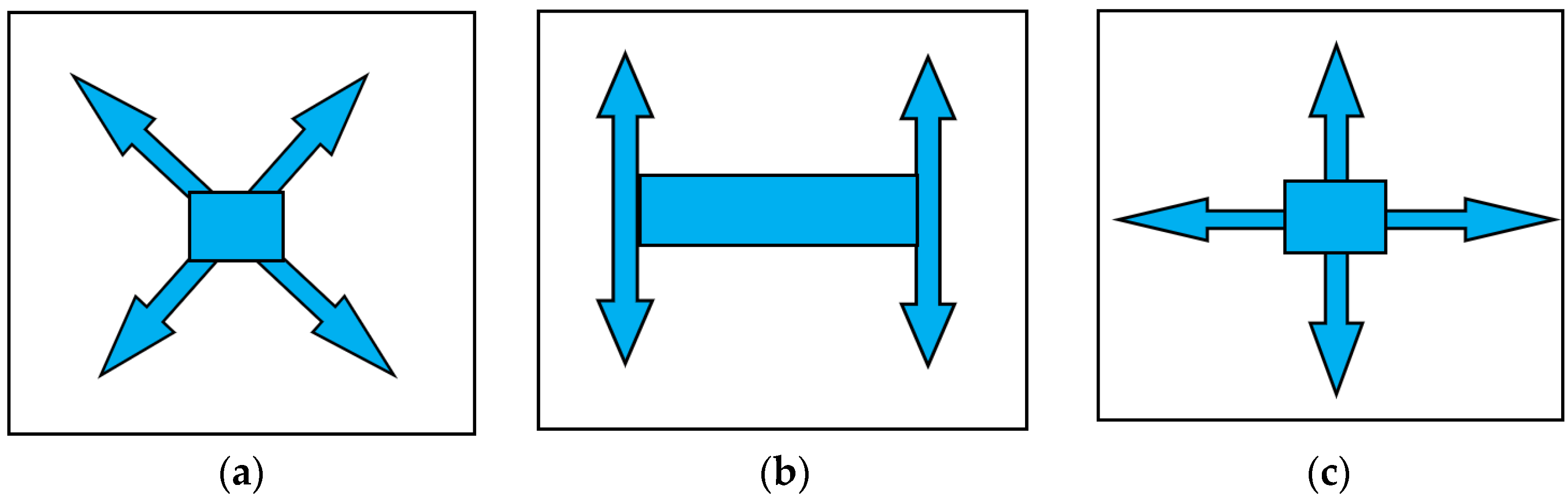
Figure 2 shows different drone configurations: the H, X, and + designs. Each has its unique set of advantages and applications [14]. The X configuration, which has four rotors forming a symmetrical X shape, is the most versatile in the case of precision agriculture. Its inherent stability and agility make it well-suited for navigating the intricacies of agricultural landscapes. The symmetrical layout facilitates balanced thrust, providing enhanced maneuverability and precise positioning.
In contrast, the H configuration, with arms extending vertically and horizontally, offers stability but may sacrifice some agility in specific scenarios, with being heavy as a disadvantage. The + configuration, with arms extending horizontally, lacks behind from X regarding symmetrical thrust distribution characteristics. Considering all these variations, the X configuration’s versatility and balanced thrust make it an optimal choice in agricultural settings where precision is paramount. While the H and + configurations may excel in stability, the nuanced requirements of precision agriculture underscore the unique advantages of the X design in delivering reliable and accurate results [15].

2. Materials and Methods

The innovation of a high-performance quadcopter drone chassis for this very need necessitates an exploration of innovative materials and advanced methods. This section shifts to the Materials and Methods employed in the novel 3D-Printed Generative Design approach. The design objectives introduced earlier set the stage for a comprehensive examination of materials that meet the criteria of lightweight construction, structural integrity, and efficiency.

2.1. Generative Design Using Topology Optimization

Generative design stands out as a method in design exploration involving the parametric variation of design geometry to evaluate output performance [16,17]. Recent shifts towards topology optimization as a design generator, rather than traditional design parameterization, have been a trend. This innovative approach leverages cloud computing to generate numerous designs [18,19] concurrently. Unlike conventional topology optimization aiming for an optimal design, according to Matejka [20], generative design manipulates problem definition parameters, unlike parametric design, which directly alters geometric parameters. The primary goal of generative design is to explore options that meet structural requirements and cater to different needs. The generative design process encompasses four stages:
  • Setting design parameters and goals;
  • Generating designs through topology optimization with varied parameters;
  • Studying options, iterating, and selecting the optimal design;
  • It is manufactured using the 3D-printing method [21].
Figure 3 represents a detailed methodology of Generative Design, which includes a step-by-step algorithmic milestone according to which this design process occurs.

2.2. Method of Topology Optimization

Topology optimization, often known as the material distribution method, has roots in widespread application across various fields. The fundamental idea revolves around the efficient distribution of materials within a given design area without any predetermined structure [22,23,24]. Various approaches like homogenization and level-set methods exist; here, we opted for a density-based approach, where the density of elements influences the material distribution. In particular, we employed the solid isotropic material with the penalization (SIMP) technique, depicting clear distinctions between high and low-density areas, essentially leading to a design improvement [21]. Topology optimization is a great way to make a light and strong drone chassis for precision agriculture, as far as this very area of research is concerned. It helps to use the right amount of material in the right places so the chassis can hold up well and not be too heavy. This is important for drones in precision agriculture, where they need to be fast and efficient. Topology optimization also lets us try out new and creative shapes that we might not think of otherwise. By moving material around based on what the chassis needs, we can make it fit for different forces and pressures that the drone faces. In the end, topology optimization helped make a light and tough drone chassis that met the needs of precision agriculture due to its better performance and quality. Figure 4 shows this process’s detailed block diagram [25].

Density-Based Approach for Topology Optimization

This approach is a standard method for topology optimization that uses a variable called density to control how much material is present in each part of the structure, varying from 0 (no material) to 1 (full material) or somewhere in between (porous material). In this, solid isotropic material with penalization (SIMP), a density-based approach that uses a formula to relate the density to the stiffness or permeability of the material, is used, which helps to avoid intermediate densities and clearly distinguish between solid and void regions. The basic formulation of SIMP for minimization is written as the below equations [21,25,26]:
Minimize : S = 1 2 U T C U Elastic   Equation
Subject   to : C U = F Static   Equation
ρ i 0,1 , i Design   variables
g = i n ρ i V o 0 V o l u m e t r i c   c o n s t r a i n t s
where U is a displacement vector, C is a global stiffness matrix, S is the compliance, n is the number of elements, ρ i is the element’s design variable (i.e., density) in which 0 i 1 , and Vo is the volume of the design domain, with g being the volumetric constraint for the given topology optimization process. Like filtering techniques, many studies were conducted to enhance this process’s performance. Similarly, the 99-line or 88-line MATLAB codes are renowned methods for performing topology optimization processes to attain results with systematic weight distributions only where needed [21,26].

2.3. Thrust and Performance Calculations

One of the critical aspects of designing a drone is calculating the thrust and performance, which will help us define the thrust required for the given loading and then the power developed, further assisting in calculating ratios of thrust to weight and power-to-weight. The motor is essential for the quadcopter because it helps it fly and move. The motor force is called thrust, which pushes the quadcopter up. Each motor on the quadcopter makes a different amount of thrust [27], which is given by Equation (5):
T h r u s t   p e r   M o t o r = T o t a l   W e i g h t × 2 N u m b e r   o f   M o t o r s
As per the thrust produced, the power obtained per motor is given by Equation (6), as per the previous work [27].
( T h r u s t   p e r   M o t o r ) 2 = π 2 × ( P r o p e l l e r   D i a m e t e r ) 2 × D e n s i t y × ( P o w e r ) 2

2.4. Load Definition and Calculations

A quadcopter chassis must handle different kinds of loads when it flies, such as the push from the motors, the twists caused by motor rotations, and the gravity of the whole system [28]. The propellers push the chassis with their force, creating changing pressure points. The motors also create twists that affect how the chassis stays balanced and oriented in the air. On top of that, the quadcopter and anything it carries has a constant pull from gravity on the chassis. These loads require a robust chassis design that can handle both steady and changing stresses, making sure the quadcopter stays in one piece, stable, and efficient during precision agriculture tasks. Figure 5 shows a schematic of the distribution of loads that are exerted on the chassis of X design configuration during the time of flight, where F1, F2, F3, and F4 are the thrust forces from individual motors; M1, M2, M3, M4 are the moments induced by the rotors; Phi (φ), Theta (θ), Psi (Ψ) are the respective roll, pitch and yaw angles of drone; and F is the total weight load on the chassis [29].

2.5. Material Selection

The choice of materials plays a pivotal role in achieving optimal power-to-weight (P/W) and thrust-to-weight (T/W) ratios. Lightweight materials have been used for the chassis design to reduce weight significantly. Materials such as aluminium alloys, titanium alloys, materials like Polylactic Acid (P.L.A.), Acrylonitrile Styrene Acrylate (A.S.A.), Acrylonitrile Butadiene Styrene (A.B.S.), and Nylon 6/6 have become instrumental in enhancing the efficiency and performance of drones [30]. However, P.L.A., A.B.S. [14] and Nylon 6/6 [11] (the same used in a current market leader product, DJI F450) are only considered for this study, which proves to be the most suitable for further manufacturing stages and performed through 3D printing. As P.L.A. boasts lower production costs due to its biodegradable nature, A.B.S. provides durability at a competitive price point, and Nylon 6/6 will cost less than that in DJIF450 due to optimized usage in manufacturing. Also, producing significant numbers through 3D printing would reduce the overall cost. The properties of the selected materials are compared in Table 2, which shows the mechanical properties of the materials. Among the selections, A.B.S., known for its durability and impact resistance, finds application in the construction of drone arms and central base, providing structural integrity with the tendency to bend slightly before breaking without compromising weight [31]. P.L.A., a biodegradable, stiffer and lightweight material, is well-suited for drone arms and landing gear, contributing to reduced overall weight without sacrificing strength [32]. Nylon 6/6, valued for its high tensile strength and flexibility, proves ideal for crafting drone landing gear, ensuring a balance between durability and weight efficiency [11]. Also, considering the thermal properties of these materials, as the electronic components of the drone for the specified application do not produce that much heat as rejection, materials [15] such as A.B.S. can easily be considered and can be processed further into the study of generative design. This selection of materials for specific drone components underscores an approach to lightweight chassis, ultimately optimizing the power-to-weight and thrust-to-weight ratios. The following sections will confirm the final selection of the materials for specific parts based on the property’s comparison, which will be achieved after the design process.
Utilizing these materials in 3D printing allows for intricate and precise fabrication of drone components, enabling the achievement of geometries that might be challenging with traditional manufacturing methods. The compatibility of these materials with 3D printing facilitates the production and allows for rapid prototyping and customization.

2.6. Designing of Drone Parts

Covering up the generative design process involving the following steps and results in a novel quadcopter chassis design [34,35]. The basic methodology for the same is shown in Figure 6.

Definition of Geometries of the Quadcopter Chassis

Starting with the drone design, the central part is treated as the starting geometry, which is also created using generative design, followed by the arms and the landing gear, which combined form a drone chassis for the specified application. As Figure 6 of Section 2.6 illustrates, the process starts by defining the preserved geometries with one of the geometry types in the design space. It is assigned to bodies to incorporate them into the final shape of the design. Bodies assigned a preserved geometry display in green on the canvas of the software workspace. They do not change during the generation of outcomes [36].
With the preserved geometries, the obstacle geometries go hand in hand, which specifies where and where, but the generative design will not assert material in the design outcome, holding the rest of all conditions and variables true. It is assigned to bodies to represent spaces that are to be avoided in the design. Bodies assigned an obstacle geometry are displayed in red on the canvas. They represent the empty spaces where material is not created during the generation of outcomes. The outcomes without the obstacle geometry body in the model can also be generated [36]. The figures below show the preserved and obstacle geometries for the components in Table 1 of Section 1. Figure 7 shows the respective geometries of the base central part of the quadcopter, Figure 8 shows that of the arms and Figure 9 shows the landing gears of the drone.
After defining the respective geometries, the constraints and loadings are allocated for applying the drone chassis in precision agriculture [27], which had been defined and acted upon, as per the ones shown in Section 2.4, on the preserved geometries of the study. The following section shows a pictorial representation of the loads applied on the chassis for the generative design study of the various parts of the quadcopter. Figure 10 shows the loads acting on the upper body of the chassis which are thrust forces, rotor moments, body weight and gravity, which include the central base and arms area of the copter, whereas Figure 11 shows the ones on the lower body of the chassis that involve the presence of the landing gear of the chassis with depicted upper body loads on it [37].
A progressive representation of the generative design process is presented below in Figure 12, which shows an interim design of the drone body and the landing gear. This representation provides an outline of the topology of the structure after the processing of the generative design study.

3. Results

This section presents the results of our new research in creating a quadcopter chassis for precision agriculture using 3D printing and generative design. This section explains the benefits and learnings of combining the latest technology and creative design ideas. We also explore the numbers and quality of our new approach, unveiling a complete picture of the improved quadcopter chassis made for precision agriculture needs.

3.1. Evaluation of Thrust and Performance Loads

With reference to Equation (5) in Section 2.3, the thrust required per motor that is used for the quadcopter to maneuver and fly over the designated area as per the specified application should be enough to handle, pick and deliver the load, i.e., total load, to fulfill the core objective of the study, with maintaining the light weight of the chassis. The correct estimation of the load on the chassis, without the payload, is stated in Table 3, which specifies the individual weight of each component that must be placed on the chassis for its smooth operation for this task.
Using Equation (5) from Section 2.3, and considering the total weight to be 1700 g and the number of motors being 4, the required thrust per motor as per the above Equation is:
T h r u s t   p e r   M o t o r = 1700 × 2 4 = 850   g = 8.33   N
The total thrust force by the motors on the chassis will be the product of the result from the above Equation (7) and the number of motors and is provided in Equation (6):
T o t a l   T h r u s t = 850 × 4 = 3400   g   o r   33.32   N
The power produced, depending upon the propeller parameters that are being installed on the rotor, using Equation (6) of Section 2.3, is as follows:
( T h r u s t   p e r   M o t o r ) 2 = π 2 × ( P r o p e l l e r   D i a m e t e r ) 2 × D e n s i t y × ( P o w e r ) 2
Considering the propeller diameter be 0.254 mm [40], the density of air as 1.225 kg/m3 [27], and the thrust obtained from Equation (7), the power produced will be:
( 8.33 ) 2 = π 2 × ( 0.254 ) 2 × 1.225 × ( P o w e r ) 2
P o w e r = 8.33 2 × 2 ( 0.254 ) 2 × 1.225 × π = 23.64   W
The needed thrust of 3400.00 g was with the minimum load factor, i.e., only the quadcopter’s essential parts. This thrust will be much more than the copter’s generative outcomes weight without payload. Even with 1 kg of payload, i.e., 1000 g, its total weight will still be lesser than the motors’ thrust, i.e., ~2700.0 g < 3400.00 g.

3.2. Loads on the Chassis

The quadcopter’s various parts undergo various loading conditions, which majorly comprise the weight loads, thrust loads and rotor moments, which are individually discussed in a separate equation for each, stated below:
From Equation (8) Section 3.1, the value obtained for the thrust loads is 3400 g or 33.32 N.
For the loads by the weight of the chassis, with a total of 2700 g by Equation (8);
T o t a l   W e i g h t   L o a d s = 2700   g × m 101.97   s 2 = 26.5   N
When the loads from the rotor placed at the arms are calculated, as applied in two directions—one clockwise and the other in anti-clockwise direction to allow the drone to fly in the desired direction and obey the aerodynamic laws. The values of the motor parameters include the maximum current being 16 Ampere (16A) and Motor K.V., i.e., the R.P.M./Volt is 1400 [40]:
R o t o r   M o m e n t = 60 × M a x i m u m   C u r r e n t 2 π × K V
R o t o r   M o m e n t = 60 × 16 2 π × 1400 = 0.11   N m
For the landing gears, the total body weight will be their action load when the chassis lands.

3.3. CAD Models

The CAD models of the parts are prepared using the concept of generative design using Autodesk Fusion 360 software, which includes the design of all the quadcopter parts stated in Table 1 of Section 1. This section includes the final outcomes of the generative design process selected based on the parameters necessary for our study, i.e., body mass and factor of safety maintained at a minimum of or above 1.2. Figure 13 shows the final design of the drone’s central base part, which was processed using the materials of Nylon 6/6, A.B.S. and P.L.A., with a detailed tabular representation of the parameters of the obtained outcomes, which assists in making a clear decision about which to choose, and is represented in Table 4 below.
For the drone’s arm section, the P.L.A., A.B.S. and Nylon 6/6 materials are used and depicted in Figure 14, with a detailed tabular comparative database to select and come upon the best possible outcome as a solution, which is represented in Table 5.
Figure 15 represents the drone’s landing gear, which P.L.A. and A.B.S. process under the generative design integrated topology optimization, and a detailed comparative database of the best choices of material is shown in Table 6.
After the successful generation of the drone sections, the complete drone chassis is designed by assembling these sections as an outcome, and is represented in Figure 16.
Further to designing these outcomes, the generated outcomes are analyzed based on the specified loading conditions, which will simulate its specified field of application. The generated topology optimized outcomes when processed through the simulation window of the Autodesk Fusion 360 software. The results are represented in Figure 17, which represents the behavior of the chassis with an A.B.S. upper body and P.L.A. lower body under the loading conditions, and also provides results related to the factor of safety, stresses and displacements. A similar representation in Figure 18 shows the drone with an A.B.S upper body as a central part and a Nylon 6/6 arm section. This representation is similar to DJI drones, notably the DJI F450, renowned for its widespread popularity and sales due to their reliability and advanced features. However, some considerations include its limited customization options, relatively heavier weight and standardized structure. In the following section, a detailed performance analysis is presented.

3.4. Performance Study and Comparison

Focusing on the analysis of the performance of the designed drone chassis, Table 7 lists the vital properties required to define the best results and provides a comparison of the novel topology-optimized generative-designed quadcopter chassis with the DJI F450 chassis [31], which is well known for its applications and operations. It was observed that the testing data for comparison of this drone are available at 20 N [41], showing less than the weight conditions of our study. However, the results obtained from the generative design proved to be better than that of the comparison.
The thrust-to-weight ratios and power-to-weight ratios of the drones, designed using the topology optimization, can be found by the following: Equation (15) is used to find the thrust-to-weight ratios as:
T : W = T o t a l   T h r u s t   b y   M o t o r s T o t a l   W e i g h t   t o   b e   l i f t e d
The total thrust produced by the selected motor, i.e., A2212/10T 1400 KV, is 1000 g with a 1045 propeller and 3S LiPo battery [42], which will be utilized in the drone’s functioning.
The total weight to be lifted varies for A.B.S. and Nylon 6/6 due to the differences in their body mass, including the upper body and the landing gear. However, this can be found by using Equation (16) for A.B.S. and Equation (17) for Nylon 6/6, with relevant data from as in Table 7 as:
T o t a l   w e i g h t   f o r   A B S = C r u b   W e i g h t + P a y l o a d + C h a s s i s   m a s s = 2275   g
T o t a l   w e i g h t   f o r   N y l o n 6 / 6 = C r u b   W e i g h t + P a y l o a d + C h a s s i s   m a s s = 2284   g
T : W   f o r   A B S = 3400 2275 = 1.49
T : W   f o r   N y l o n 6 / 6 = 3400 2284 = 1.48
Therefore, the thrust-to-weight ratios achieved, at full payload, for A.B.S. and Nylon 6/6 drones are calculated by Equations (18) and (19). In addition, with no external load, with total weights being only the scrub and the chassis mass, it can reach up to 3.1, significantly improving efficiency and productivity. Also, the power-to-weight ratios of the drone can be determined by Equation (20), which is as follows:
P : W = T o t a l   P o w e r   b y   M o t o r s T o t a l   W e i g h t   t o   b e   l i f t e d
Where total power was determined to be 23.64 W by one motor from Equation (6) of Section 3.1, for four motors, the total power is 94.56 W. From Equations (21) and (22):
P : W   f o r   A B S = 94.56 2.275 = 41.56   W / K g
P : W   f o r   N y l o n 6 / 6 = 94.56 2.284 = 41.4   W / K g
which is well above the recommended values of power-to-weight ratio for a UAV [43].
For the values of thrust-to-weight and power-to-weight ratios for the comparative chassis of F450 by using Equations (15) and (20), respectively:
T o t a l   w e i g h t   f o r   D J I   F 450 = C r u b   W e i g h t + P a y l o a d + C h a s s i s   m a s s [ 30 ] = 2431   g
So, the thrust-to-weight ratio and the power-to-weight ratio for the commercially sound DJI F450 drone chassis, from Equations (24) and (25):
T : W   f o r   D J I   F 450 = 3400 2431 = 1.39
P : W   f o r   D J I   F 450 = 94.56 2.431 = 38.89   W / K g

4. Discussion

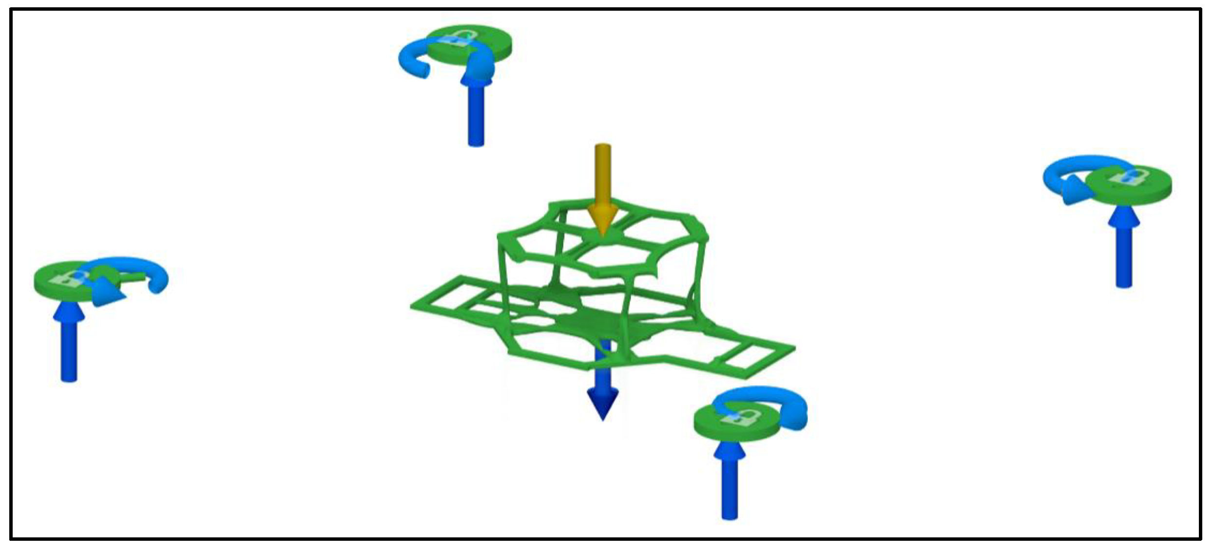
The results of this research exhibit a significant gain in drone design, where all components have been meticulously crafted with the most optimized parameters through topology optimization-integrated generative-design methodology using Autodesk Fusion 360. This approach, with potential design constraints such as structural integrity, durability, and standards and choosing the relevant materials, yielded a quadcopter chassis that outperforms the well-established DJI F450, a prominent commercial drone. The optimized topology enhances the structural integrity of individual components and contributes to a more cohesive and efficient overall design. The superior performance metrics, including power-to-weight and thrust-to-weight ratios, underscore the success of our generative design approach. This comparative advantage over a widely recognized commercial drone highlights the potential of our methodology to push the boundaries of drone technology, particularly in the realm of precision agriculture, where the demand for enhanced performance and agility is paramount. The following discussion will delve into the nuanced aspects of these results, elucidating the specific advantages and implications for the field.
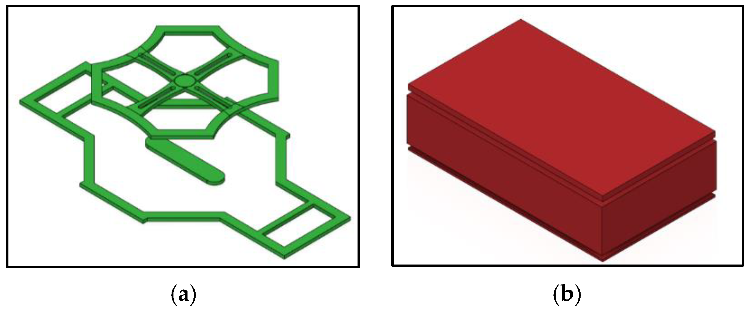
The design of the quadcopter, as it was meant to be lightweight, has good structural conduct and is efficient; the selections made for every component were very logical. These selections were made after accounting for all possible considerations. For the central part of the drone base, A.B.S. material is prioritized over P.L.A., as A.B.S. is stiffer. However, A.B.S.’s light weight also tends to make the material bend a bit, protecting against breakage in times of unexpected loadings. Table 4 of Section 3.3 shows that the properties achieved in A.B.S. are very similar to those of P.L.A., with the advantages of being lightweight, easily accessible and cost-effective.
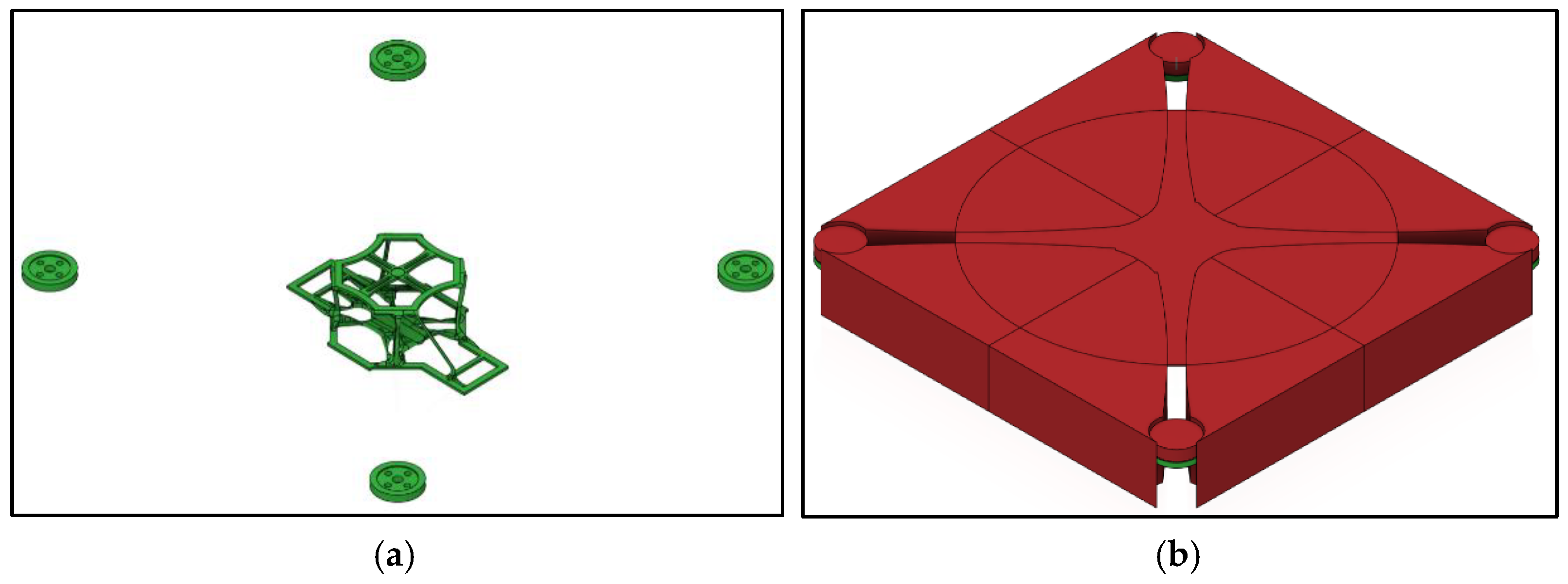
For the arm’s section of the quadcopter, the materials of A.B.S., P.L.A. and Nylon 6/6 are considered, but with P.L.A. being stiffer and heavier, it is not recommended for our purposes, as discussed in previously referred studies. Therefore, the design outcomes of A.B.S. and Nylon 6/6 were processed and then analyzed based on the variations in their properties. It was observed that both materials do not differ much in terms of body mass, von Mises Stresses, and body global displacement, as shown in Table 5 of Section 3.3.
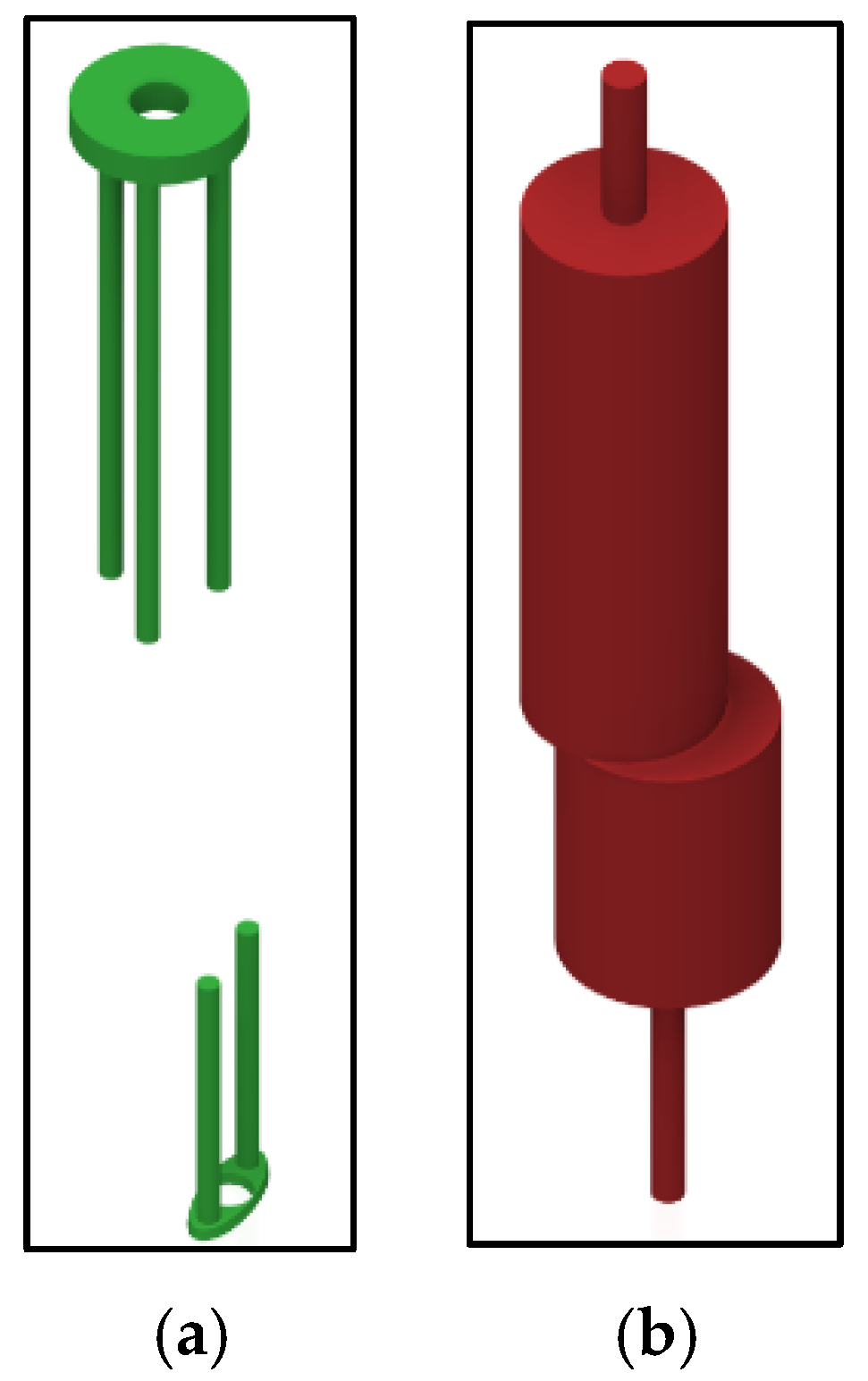
In the case of the landing gear, the body part must be strong enough to sustain the upper body’s load during landings and act as a protective part in rough terrains and surroundings. It is imperative to make the design stronger yet lighter in weight, so the components made from P.L.A. and A.B.S. were exclusively taken under the study’s consideration. Also, these materials were strongly suggested by previous researchers, so when applied to the study, they provided similar results. Still, P.L.A. surpassing A.B.S. in some fields with the same body mass makes it a better choice for the landing gear.
So, with the chosen materials, parameters and designs of the sections of the quadcopter chassis, a whole assembly was created that provided outperforming results in each domain, with surpassed factor of safety values, lesser stress values, lighter body frames, and better results in every aspect than the market’s popular drone chassis, as listed in Table 7 of Section 3.4. The drone chassis for both materials was able to provide outstanding thrust-to-weight and power-to-weight ratios with the designated load conditions and application domain. However, the design of the chassis is associated with some constraints, such as the utilization of the chassis within the limitations of precision agriculture tasks like field mapping, monitoring, and pesticide distribution (up to 1 kg as payload), which are small but tedious tasks for humans. Also, the generative design produces an organic design manufactured by non-conventional processes, i.e., subtractive or conventional manufacturing processes would not be able to compensate for any modification or repair in the design if required. Although the generative study facilitates the application of manufacturing constraints as a specific process to achieve a significant weight reduction, these very non-conventional processes, such as additive manufacturing and materials, should be utilized.
Further research in the future for this subject will include the experimental testing of the generative design in real-world scenarios, i.e., testing in actual agriculture fields with real-time conditions, considering practical agricultural applications and various outdoor environmental factors such as wind speed and temperature as noted above, which will significantly impact drone performance. A systematic comparison of the generated drone performance in real-world conditions in full functionality with all components and payload with the experimental and field tests of DJI F450 will also be considered in the future scope of the study. Also, improving the power-to-weight and thrust-to-weight ratios for greater payload capacities will be considered within the same volumetric limits to further improve its performance. Heavy-duty applications will also be included in future studies.

5. Conclusions

The generative design employed in our research demonstrated superior performance across multiple dimensions compared to traditional designs, surpassing currently available drones in the market that enjoy widespread usage. The results for various parameters, directly affecting the stability, flight time, efficiency, mass production rates and cost of the drones, were achieved to be well advanced from DJI F450, a well-known commercial drone. The values of generated topology-optimized chassis have reduced weight values of 50%, which directly result in reduced costs up to similar extents, i.e., 50%, with power-to-weight and thrust-to-weight ratios increased by 6.06% and 6.75%, respectively, and incremental improvements of at least 11.8% in terms of factor of safety and 70% in reduced stress values. The design also exhibits shorter production times as additive manufacturing favours it.
These substantial positive outcomes have far-reaching implications for the drone industry. First and foremost, the enhanced design contributes to better operational efficiencies, allowing for more precise and agile manoeuvres during flight. The optimization achieved through generative design also translates into longer flight times, a critical factor in applications such as precision agriculture, where extended aerial coverage is paramount. Additionally, the reduced power consumption inherent in our design prolongs the drone’s operational duration and aligns with sustainability goals, making it environmentally friendly. The prospect of mass production with cost-efficient availability is another significant benefit, enabling broader access to advanced drone technology. Our generative design approach aims to revolutionize the drone industry, offering a holistic enhancement that extends beyond individual components to benefit users through improved efficiency, sustainability and cost-effectiveness.

Author Contributions

Conceptualization, R.M. and A.B.; Funding acquisition, S.S.; Investigation, A.B. and S.D.; Methodology, R.M., B.H. and A.S.; Project administration, R.M. and S.S.; Software, A.B.; Supervision, R.M.; Visualization, A.B.; Writing—original draft, A.B. and S.S.; Writing—review & editing, R.M., A.S., S.S. and B.H. All authors have read and agreed to the published version of the manuscript.

Funding

This work is supported by the Science and Engineering Research Board (S.E.R.B.), DST, India, under the MATRICS Scheme, file number M.T.R./2022/001029. The authors extend their appreciation to the AgAutomate Pvt. Ltd., Pune, India and Deanship of Research and Development at Thapar Institute of Engineering and Technology, India, for supporting this work through Consultancy Grant under AgA/RT/CG/2022/0101 and Seed Research Grant under Grant Number TIET/RF-68.

Data Availability Statement

The data presented in this study are available on request from the corresponding author. The data are not publicly available due to privacy.

Conflicts of Interest

The authors declare no conflict of interest.

References

  1. Shelare, S.D.; Aglawe, K.R.; Khope, P. Computer Aided Modeling and Finite Element Analysis of 3-D Printed Drone. Mater. Today Proc. 2021, 47, 3375–3379. [Google Scholar] [CrossRef]
  2. Puri, V.; Nayyar, A.; Raja, L. Agriculture Drones: A Modern Breakthrough in Precision Agriculture. J. Stat. Manag. Syst. 2017, 20, 507–518. [Google Scholar] [CrossRef]
  3. Waqas, M.M.; Ali, S.; Muthmainnah, M.; Rustam, M.A.; Khang, A. Unmanned Aerial Vehicles (UAVs) in Modern Agriculture. In Handbook of Research on AI-Equipped IoT Applications in High-Tech Agriculture; Advances in environmental engineering and green technologies book series; IGI Global: Hershey, PA, USA, 2023; pp. 109–130. [Google Scholar]
  4. Balaji, K.; Babu, V.; Sulthan, S. Design and Development of Multipurpose Agriculture Drone Using Lightweight Materials. SAE Int. J. Aerosp. 2022, 16, 177–183. [Google Scholar] [CrossRef]
  5. Singh, J.; Sharma, U.; Mallick, R. Sustainable Aviation: A Generative Design Approach. In Proceedings of the Global Conference on Flexible Systems Management under the Theme of Sustainability, Flexibility and Digital Transformation, Mohali, India, 9–11 December 2022. [Google Scholar]
  6. Sharma, U.; Singh, V.; Haorongbam, B.; Sharma, A.; Mallick, R. Optimizing Quadcopter Chassis through Generative Design: A Novel Approach. In Industry 4.0 and Advanced Manufacturing; Springer Nature: Singapore, 2024. [Google Scholar]
  7. Bikov, T.; Mihaylov, G.; Iliev, T.; Stoyanov, I. Drone Surveillance in the Modern Agriculture. In Proceedings of the 2022 8th International Conference on Energy Efficiency and Agricultural Engineering (EE&AE), Ruse, Bulgaria, 30 June–2 July 2022. [Google Scholar] [CrossRef]
  8. Alam, A.; Chauhan, A.; Khan, M.T.; Jaffery, Z.A. Drone-Based Crop Product Quality Monitoring System: An Application of Smart Agriculture. In Agri-Food 4.0; Advanced Series in Management; Emerald Publishing Limited: Leeds, UK, 2022; pp. 97–110. [Google Scholar]
  9. Schrurs, S. Contributions of Generative Design Tools to Mechanical Design. Master’s Thesis, Ecole Polytechnique de Louvain, Université Catholique de Louvain, Ottignies-Louvain-la-Neuve, Belgium, 2021. Available online: http://hdl.handle.net/2078.1/thesis:30737 (accessed on 21 December 2023).
  10. Martins, J.R.R.A.; Lambe, A.B. Multidisciplinary Design Optimization: A Survey of Architectures. AIAA J. 2013, 51, 2049–2075. [Google Scholar] [CrossRef]
  11. DJI-Flame Wheel, A.R.F. Kit. Available online: https://www-v1.dji.com/flame-wheel-arf/spec.html (accessed on 21 December 2023).
  12. ROBOTBANAO: Make Your Own Bot. Available online: https://www.robotbanao.com/products/universal-high-landing-gear-skid-for-dji-f450-f550-sk480-multirotor-quadcopter-black?_pos=1&_sid=1c4e53eb1&_ss=r (accessed on 21 December 2023).
  13. Microsoft Bing: Image Creator from Designer. Available online: https://www.bing.com/images/create/a-drone-image-to-be-used-in-agriculture-with-a-lig/1-65910c5a7bd645889312ff7f55f6578f?id=nuMkiLtZc9iJZ%2boME0HdhQ%3d%3d&view=detailv2&idpp=genimg&noidpclose=1&FORM=SYDBIC (accessed on 27 December 2023).
  14. Shukla, D.; Komerath, N. Multirotor Drone Aerodynamic Interaction Investigation. Drones 2018, 2, 43. [Google Scholar] [CrossRef]
  15. MohamedZain, A.O.; Chua, H.; Yap, K.; Uthayasurian, P.; Jiehan, T. Novel Drone Design Using an Optimization Software with 3D Model, Simulation, and Fabrication in Drone Systems Research. Drones 2022, 6, 97. [Google Scholar] [CrossRef]
  16. Shea, K.; Aish, R.; Gourtovaia, M. Towards Integrated Performance-Driven Generative Design Tools. Autom. Constr. 2005, 14, 253–264. [Google Scholar] [CrossRef]
  17. Krish, S. A Practical Generative Design Method. Comput.-Aided Des. 2011, 43, 88–100. [Google Scholar] [CrossRef]
  18. McKnight, M. Generative Design: What It Is? How Is It Being Used? Why It’s a Game Changer. KnE Eng. 2017, 2, 176. [Google Scholar] [CrossRef]
  19. Brossard, M.; Gatto, G.; Gentile, A.; Merle, T.; Wlezien, C. How Generative Design Could Reshape the Future of Product Development; Mckinsey Co.: Chicago, IL, USA, 2020. [Google Scholar]
  20. Matejka, J.; Glueck, M.; Bradner, E.; Hashemi, A.; Grossman, T.; Fitzmaurice, G. Dream Lens-Exploration and Visualization of Large-Scale Generative Design Datasets. In Proceedings of the 2018 CHI Conference on Human Factors in Computing Systems, Montreal, QC, Canada, 21–26 April 2018. [Google Scholar] [CrossRef]
  21. Oh, S.; Jung, Y.; Kim, S.; Lee, I.; Kang, N. Deep Generative Design: Integration of Topology Optimization and Generative Models. J. Mech. Des. 2019, 141, 111405. [Google Scholar] [CrossRef]
  22. Bendsoe, M.P.; Sigmund, O. Topology Optimization: Theory, Methods, and Applications; Springer Science & Business Media: Berlin/Heidelberg, Germany, 2003. [Google Scholar]
  23. Bendsøe, M.P. Optimal Shape Design as a Material Distribution Problem. Struct. Optim. 1989, 1, 193–202. [Google Scholar] [CrossRef]
  24. Youtube. Introduction to Topology Optimization Part ¼. Available online: https://youtu.be/5ocnVS_HvdY?si=IoFtJpsVJw0h1VND (accessed on 22 December 2023).
  25. Youtube. Introduction to Topology Optimization Part 2/4. Available online: https://youtu.be/eF_piSm3Fc?si=dNz5G8s5Famv3GYC (accessed on 22 December 2023).
  26. Sigmund, O. A 99 Line Topology Optimization Code Written in Matlab. Struct. Multidiscip. Optim. 2001, 21, 120–127. [Google Scholar] [CrossRef]
  27. Shelare, S.D.; Belkhode, P.; Nikam, K.C.; Yelamasetti, B.; Gajbhiye, T. A Payload Based Detail Study on Design and Simulation of Hexacopter Drone. Int. J. Interact. Des. Manuf. (IJIDeM) 2023, 1–18. [Google Scholar] [CrossRef]
  28. Marino, S.O.; Fayazbakhsh, K. Generative Design for 3D Printing of Advanced Aerial Drones. Bachelor’s Thesis, Toronto Metropolitan University, Toronto, ON, Canada, 2023. [Google Scholar] [CrossRef]
  29. Karim, C.B. The Design and Development of a General-Purpose Drone. Ph.D. Thesis, School of Science and Engineering, Al Akhawayn University, Ifrane, Morocco, 2020. [Google Scholar]
  30. Zhu, L.; Li, N.; Childs, P. Light-Weighting in Aerospace Component and System Design. Propuls. Power Res. 2018, 7, 103–119. [Google Scholar] [CrossRef]
  31. Bright, J.; Suryaprakash, R.; Akash, S.; Giridharan, A. Optimization of Quadcopter Frame Using Generative Design and Comparison with DJI F450 Drone Frame. IOP Conf. Ser. Mater. Sci. Eng. 2021, 1012, 012019. [Google Scholar] [CrossRef]
  32. Muralidharan, N.P.; Pratheep, V.G.; Shanmugam, A.; Hariram, A.; Dinesh, P.; Visnu, B. Structural Analysis of Mini Drone Developed Using 3D Printing Technique. Mater. Today Proc. 2021, 46, 8748–8752. [Google Scholar] [CrossRef]
  33. Matweb, Material Property Data. Available online: https://Matweb.com (accessed on 22 December 2023).
  34. Autodesk Instructables. Available online: https://www.instructables.com/Pushing-3D-Printing-by-Making-a-Drone-With-Fusion3/ (accessed on 23 December 2023).
  35. De Freitas Francisco, J.V.; Gonzales, M.A.C. Generative Design of a Cargo Drone. In Proceedings of the M.E.C.S.O.L. 2022—Proceedings of the 8th International Symposium on Solid Mechanics, São Paulo, Brazil, 17–19 October 2022. [Google Scholar] [CrossRef]
  36. Autodesk.com. Available online: https://help.autodesk.com/view/fusion360/ENU/?guid=GD-PRESERVE-GEOM (accessed on 23 December 2023).
  37. Hashim, M.Z.A.W.; Hassan, M.F. A Study on Drone Design for Packages Delivery Services. Res. Prog. Mech. Manuf. Eng. 2022, 3, 921–928. [Google Scholar]
  38. Shaw, K.K.; Vimalkumar, R. Design and Development of a Drone for Spraying Pesticides, Fertilizers and Disinfectants. Int. J. Eng. Res. Technol. 2020, 9, 1181–1185. [Google Scholar] [CrossRef]
  39. Rajput, S.G.; Thakur, M.S.; Wagh, C.V.; Mahale, M.D. A Review on Agricultural Drone Used in Smart Farming. Int. Res. J. Eng. Technol. 2021, 8, 313–316. [Google Scholar]
  40. Robu.in. Available online: https://robu.in/product/a2212-10t-13t-1400kv-brushless-motor-with-soldered-connector/ (accessed on 23 December 2023).
  41. Ahmed, F.; Zafar, M.; Mohanta, J.C. Modeling and Analysis of Quadcopter F450 Frame. In Proceedings of the International Conference on Contemporary Computing and Applications (IC3A), Lucknow, India, 5–7 February 2020. [Google Scholar] [CrossRef]
  42. Quartz Component. Available online: https://quartzcomponents.com/products/a2212-10t-13t-1400kv-bldc-motor (accessed on 23 December 2023).
  43. Rajendran, P.; Smith, H.; Yahaya, K.I.; Mazlan, N.M. Electric Propulsion System Sizing for Small Solar-powered Electric Unmanned Aerial Vehicle. Int. J. Appl. Eng. Res. 2016, 11, 9419–9423. [Google Scholar]
Figure 1. Typical quadcopter (UAV) for the specified application [13].
Machines 12 00187 g001
Figure 2. Various configurations of the drone chassis: (a) the X design, (b) the H design, and (c) the + design configurations.
Machines 12 00187 g002
Figure 3. Systematic Process of Generative Design [21].
Machines 12 00187 g003
Figure 4. Systematic process of topology optimization according to the density approach.
Machines 12 00187 g004
Figure 5. Loads on a quadcopter.
Machines 12 00187 g005
Figure 6. Process of performing generative design on Autodesk Fusion 360.
Machines 12 00187 g006
Figure 7. Geometries under design study for the central base of the drone: (a) preserved geometry and (b) obstacle geometry.
Machines 12 00187 g007
Figure 8. Geometries under design study for arms of the drone: (a) preserved geometry and (b) obstacle geometry.
Machines 12 00187 g008
Figure 9. Geometries under design study for landing gears of the drone: (a) preserved geometry and (b) obstacle geometry.
Machines 12 00187 g009
Figure 10. Loading and structural constraints of the upper body of the chassis.
Machines 12 00187 g010
Figure 11. Loading and structural constraints of the lower body of the chassis.
Machines 12 00187 g011
Figure 12. (a) Tentative topology of the drone chassis before generative design study. (b) Tentative topology of the drone’s landing gear before generative design study processing.
Machines 12 00187 g012
Figure 13. The generated outcome of the optimized drone central base: (a) isometric view of the outcome; (b) front view of the outcome; and (c) top view of the outcome.
Machines 12 00187 g013
Figure 14. The generated outcome of the optimized drone arm section: (a) isometric view of the outcome; (b) front view (top) and right side view (bottom) of the outcome; and (c) top view of the outcome.
Machines 12 00187 g014
Figure 15. The generated outcome of the optimized drone landing gear: (a) isometric view of the outcome; (b) front view of the outcome; and (c) right side view of the outcome.
Machines 12 00187 g015
Figure 16. Generated outcome of the optimized drone: (a) isometric view; (b) front view; and (c) right side view.
Machines 12 00187 g016
Figure 17. Simulation results for the applied conditions for ABS + PLA drone: (a) factor of safety results; (b) stress analysis results; and (c) displacement results.
Machines 12 00187 g017
Figure 18. Simulation results for the applied conditions for ABS + Nylone6/6 + PLA drone: (a) factor of safety results; (b) stress analysis results; and (c) displacement results.
Machines 12 00187 g018
Table 1. The drone’s parts under design.
PartNumber of PartsFunctionality
Drone Base Centre1To hold components
Drone Arms4The connection between the motors and body also stabilizes the chassis
Drone Landing Gear4Support chassis and facilitate landing
Table 2. Properties of the materials under consideration in the design study [33].
Properties/MaterialNylon 6/6ABSPLA
Yield strength (MPa)82.752049.5
Mass density (g/cm3)1.131.061.3
Ultimate tensile strength (MPa)82.7529.650
Poisson’s ratio0.350.380.39
Young’s modulus (GPa)2.932.243.5
Shear modulus (MPa)10008052399.99
Table 3. Table showing the list of components and their respective and total weight [27,38].
Part NameNo. of QuantityWeight (Grams)Total Weight (Grams)
Battery1360360
Motors647 a282
ESC632192
Propeller620120
Pixhawk12020
G.P.S.12626
Regulator12525
Radio receiver11010
Servo motor11515
Water pump12525
Other accessories 5050
Total Weight 1125
a Motor chosen for this application is A2212/10T 1400 KV [39].
Table 4. Comparison of the mechanical properties of the generatively designed drone central base with Nylon, A.B.S. and P.L.A. material.
Parameters/MaterialNylon 6/6ABSPLA
Volume (mm3)21,558.5121,838.421,821.77
Mass (kg)0.0240.0230.028
Maximum von Mises Stress (MPa)3.593.533.52
Maximum Global Displacement (mm)0.8431.0660.67
Table 5. Comparison of the mechanical properties of generatively designed drone arm selection with Nylon, A.B.S. and P.L.A. materials.
Parameters/MaterialNylon 6/6ABSPLA
Volume (mm3)119,233.544119,218.271119,229.57
Mass (kg)0.1350.1260.155
Maximum von Mises Stress (MPa)0.9340.9480.952
Maximum Global Displacement (mm)0.1770.230.147
Table 6. Comparison of the mechanical properties of generatively designed drone landing gear with A.B.S. and P.L.A. material.
Parameters/MaterialABSPLA
Volume (mm3)5484.334447.42
Mass (kg)0.0060.006
Maximum von Mises Stress (MPa)0.9891.057
Maximum Global Displacement (mm)0.3940.27
Table 7. Comparison of the mechanical properties of generatively designed drone with Nylon 6/6 and A.B.S. material with the DJI F450 quadcopter [31,41].
Parameters/MaterialNylon 6/6ABSDJI F450
Factor of Safety12.23.7393.301 for Polyamide Nylon b
Maximum Stress (MPa)6.795.3523 @ 20 N
Displacement (mm)0.2440.2964.135 @ 20 N
Strain0.0040.004-
Total Drone (Chassis+ Landing Gear) Mass (kg)0.1590.1500.282 (w/o landing gears)
Manufacturing MethodUnrestrictedAdditiveAdvanced Manufacturing
b Nylon 66 (loosely written nylon 6-6, nylon 6/6, nylon 6,6, or nylon 6:6) is a type of polyamide or nylon.
Disclaimer/Publisher’s Note: The statements, opinions and data contained in all publications are solely those of the individual author(s) and contributor(s) and not of MDPI and/or the editor(s). MDPI and/or the editor(s) disclaim responsibility for any injury to people or property resulting from any ideas, methods, instructions or products referred to in the content.

