1. Introduction
Vibrations in technical systems are caused by the movement of individual parts of non-zero-mass equipment. This motion can be induced in various ways, such as rectilinear motion, motion along a curved trajectory, or rotational motion. Furthermore, vibrations may also occur due to the impact of individual equipment parts [
1].
Working machines and equipment comprise the various parts performing these movements and are, therefore, the very source of the vibration-causing forces in the whole system. Each part of the machine is of certain mass and stiffness, which allows it to oscillate in response to external forces. The machine’s parts form a mechanical resonant circuit sensitive to external influences and active excitation forces. Since each part has its own oscillation frequency, the resulting vibration comprises multiple resonant vibrations of the individual parts. The frequency of these vibrations depends not solely on the excitation frequency but also on the intrinsic characteristics and oscillation frequencies of the individual machine parts [
2,
3,
4]. Therefore, each machine has its own vibration manifestations characteristic of its specific operating conditions and design. However, when the machine is in operation, the connections of the individual parts change, for example, by wearing out the bearings (clearances increase), changing the mass of the worn parts, etc. These facts also result in a change in the vibration of the machine in operation. This change in vibration is characteristically different for each type of machine; however, it also contains much information about the changes that have occurred in the design of the machine [
5,
6].
Any fault or deficiency in the equipment can specifically affect its vibration. For example, a damaged bearing system can cause irregular vibrations, while an unbalanced rotor can produce periodic vibrations with a specific frequency. A malfunction can affect the frequency and amplitude of the vibration. For example, cracks in the material can change the vibration frequency, while weakening the structure can increase amplitude [
7,
8,
9]. Some defects can also produce characteristic sounds associated with vibration. These sounds can be detected with acoustic sensors and used for diagnostics. Specific damage can also affect the resonance characteristics of the device, which can cause a change in resonant frequencies and vibration intensity. Identification of localized vibrations can help narrow down the fault search. Analysis of the vibration and its characteristics can provide valuable information for identifying a specific equipment failure and determining the required repairs.
However, using vibrodiagnostics, it is sometimes impossible to clearly determine the problem with the device. Some problems can generate characteristic vibrations that can be identified. For example, bearings with worn rolling elements can create periodic pulse vibrations, while an unbalanced rotor can cause periodic vibrations with a rotational frequency. However, some equipment may have multiple simultaneous problems that cause different vibrations. These problems can mask or confuse the vibrodiagnostic analysis. The vibration of one part can affect the vibration of other parts of the equipment, making it difficult to identify the source of the problem. A wide variety of possible problems can affect equipment vibration, including bearing wear, misalignment, bearing defects, deformation, cracks, etc. Therefore, vibrodiagnostics should be combined with other diagnostic methods, such as thermal imaging, oil analysis, ultrasonic diagnostics, etc., to obtain comprehensive information about the condition of the equipment [
10].
From the perspective of the presented contribution, it is possible to state that the conducted study identified several issues with the operation of the CNC machining center milling head. These issues relate to the low lifespan of bearings, increased play in the bearing arrangement, high vibrations, and quality deficiencies in machined components. In the context of the conducted measurements and subsequent analyses, it is necessary to consider possible uncertainties and the importance of measurement accuracy. [
11] Measurement uncertainty manifests as variability in measurement results, which can be caused by various factors. These factors may include inaccuracies in measuring instruments, work procedures, pre-analytical phase factors, and other disruptive influences [
12,
13]. The uncertainty of the measurement result characterizes the range of values (interval of tolerance) that can be rationally assigned to the measured quantity. Simply put, it is the spread of values of the measured quantity around the measurement result, which is expected to include the true value of the measured quantity. [
12,
13] Accuracy in diagnostic measurements is highly important. For example, measurements of vibrations and the microgeometry of bearings must be performed with high precision to ensure reliable results. If these measurements are not accurate, it can lead to incorrect conclusions and improper decisions regarding maintenance and repairs.
Reliable operation of the CNC machining center milling head represents a complex process involving many factors. It is important to regularly monitor and analyze these factors to prevent problems and ensure long life and trouble-free operation. In this process, it is crucial to consider all potential uncertainties related to measurement accuracy when making decisions about maintenance and repairs.
2. Methodology and Research of the Correlation between Monitored Operating Parameters and Bearing Life in the Milling Head of the CNC Machining Center
In the present study, the authors attempted to identify a possible link between bearing damage in the CNC milling head and the lubricant quality. In addition, they also investigated the effect of corrosion on bearing functionality, temperature and friction increase, deformation of bearing inner and outer ring microgeometry, and applied axial preload during assembly. Inadequate bearing lubrication can increase friction and temperature, resulting in premature bearing wear and damage. Lack of lubricant can also cause increased friction and bearing wear. If moisture or aggressive chemical environments penetrate the bearings, corrosion can occur, damaging the bearing surface and impairing bearing performance. Increased temperature and friction in the bearings, resulting from improper lubricant or worn bearings, can cause deformation and damage. Furthermore, the microgeometry of the functional parts of the bearings can change, which can subsequently affect their proper function and cause premature wear. It is also believed that improper adjustment of the axial preload during the assembly of the bearings may contribute to premature bearing wear and damage. These aspects are critical to the successful operation of CNC equipment and require systematic maintenance and active monitoring. After conducting the study, it can be argued that the correlation lies in the interdependence and interrelationships of the monitored parameters that affect the bearings’ overall condition and service life.
Other authors and scholars have addressed similar issues. For example, Maurice L. Adams, in his monograph “Rotating Machinery Vibration”, focuses on the analysis of vibration in rotating machinery and investigates the correlation between operating conditions and vibration in various mechanical systems [
14]. The book
Condition Monitoring and Diagnostic Engineering Management by Starr, A. and Rao, B.K.N. discusses condition monitoring and diagnostic engineering management methods, including vibration analysis and the correlation between operating parameters and vibration [
15]. Tiboni, M., Remino, C. et al., in their paper “A Review on Vibration-Based Condition Monitoring of Rotating Machinery”, review the most important research trends and the most significant innovations in the different phases of vibration condition monitoring. Various signal processing, feature selection, and diagnostic techniques are analyzed, highlighting their effectiveness as a function of the aspects investigated and the results obtained in different studies [
16]. The paper “Modeling of Cutting Parameters and Tool Geometry for Multi-Criteria Optimization of Surface Roughness and Vibration via Response Surface Methodology in Turning of AISI 5140 Steel” by Kuntoğlu, M., Aslan, A. et al. presents an implemented systematic study to determine the optimum cutting conditions, vibration, and surface roughness analysis at different cutting speeds, feeds, and cutting edge angles using Response Surface Methodology (RSM) [
17]. Hou, R. and Xia, Y. discuss the recent trends in methods for damage identification through vibration measurements over the past 13 years. The presented review aims to assist researchers and practitioners in effectively implementing existing damage detection algorithms and in developing more reliable and practical methods for building structures in the future [
18]. The paper “Dynamic modeling and stability analysis of a rotor-bearing system with bolted-disc joint” presents research on the influence of bolted joints on the rotor dynamics in rotating machines, which can cause various motion states with the manifestation of vibration generation. The present work provides a theoretical basis for investigating the performance of the bolted-joint rotor-bearing system and preventing failures caused by changes in bolted-joint stiffness [
19]. The monograph “Vibration utilization engineering” by Wen, B., Huang, X., Li, Y., and Zhang, Y. focuses on mechanical vibration theory and applications, including the correlation between operating parameters and vibration in various systems [
20]. From the point of view of the currently ongoing industrial revolution, the paper “Research on vibration monitoring and fault diagnosis of rotating machinery based on Internet of things technology” by Zhang, X., Rane, K. et al. is of great relevance since it deals with the design of a fault and error detection system using the implementation of machine learning algorithms. The proposed algorithm can extract the most relevant feature set and thus present an accurate classification of faults [
21]. The artificial intelligence tools implemented in a predictive maintenance system using real-time monitoring data are described in the paper “Developing a predictive maintenance model for vessel machinery”. The results of this study showed that the key parameters had a stronger influence on the overall condition of the parts. In most cases, a strong correlation between the sensor data from the engineering equipment and the development of a predictive maintenance system model was demonstrated [
22].
Vibrodiagnostics has become a key tool in modern industry and machine maintenance. It enables businesses to achieve higher efficiency, safety, and reliability in their operations. Manish Vishwakarma et al., in their article “Vibration Analysis & Condition Monitoring for Rotating Machines: A Review”, identify vibrodiagnostic tools that allow the early identification of issues with worn bearings, unbalanced rotors, or other problems, ultimately leading to increased safety and performance of machines and equipment [
23]. The book “Analytical and Numerical Methods for Vibration Analyses” by author Jong-Shyong Wu provides a detailed view of analytical methods for solving vibrations in various continuous systems [
24]. The most common method involves using sensors called accelerometers. These devices measure the acceleration of the vibrating object, which is then used to calculate the amplitude and frequency of the vibration. The spectral analysis method assesses vibrations in the frequency spectrum [
25]. Using Fourier transformation, vibrations are decomposed into various frequency components. This way, characteristic frequencies associated with specific faults can be identified. The time-domain analysis method tracks vibrations over time. Using time-domain signals, periodic patterns or sudden changes in vibrations can be identified. Measurements are typically performed using accelerometers or vibration sensors and then analyzed in time series. This method can provide information about the frequency, amplitude, and time dependency of vibrations. Modal analysis is used to determine the natural frequencies of a structure or system. These frequencies are characteristic of a given object and depend on its geometry, material, and mass. Understanding natural frequencies is important for the design and optimization of structures. Modal analysis identifies modal shapes of vibration, which are characteristic patterns of deformation or movement of the structure at resonance. These modes can include bending, twisting, or pulsating. In cases of faults or damage to the structure, modal analysis can help identify weak points or undesirable vibrations, for example, in detecting cracks, fatigue failures, or unbalanced rotating parts. In the design of new structures, modal analysis is used to minimize undesirable vibrations and ensure that the structure will operate within safe frequency ranges [
26]. Measurement and analysis of vibration signals in operation is a critical process that allows obtaining information about the dynamic behavior of machines and systems. Methods of measuring and analyzing vibrations are often combined and contribute to a broader understanding of the condition and operation of mechanical systems, as well as to better maintenance planning and fault prevention.
The paper “Effects of lubrication on gear performance” by Liu, H., Zhu, C., and Parker, R. G. is noteworthy from a tribodiagnostic perspective. Optimized gear lubrication methods and lubricant formulations are needed to meet the industrial challenges associated with higher load, speed, temperature, and expected performance in multiple powertrain applications, including automotive, aerospace, and marine [
27]. Tribodiagnostics performs the role of monitoring lubricant degradation and the wear condition of machinery. Advanced analytical methods, such as spectroscopic analysis, microscopic investigations, and thermographic techniques, allow for a more detailed study of the interactions between surfaces, wear, and lubricant [
28]. The paper “Experimental Evaluation of the Influence of Microgeometry on the Tribological Characteristics of a Radial Plain Bearing” describes research on current trends in increasing the load-carrying capacity of plain bearings using friction surface texturing. The results indicate that the texture of the liners affects the performance of radial bearings. Of the three texturing patterns investigated, the one with the highest load-carrying capacity was selected, allowing the friction regime change from liquid to the boundary to be achieved at higher loads than the other texturing patterns considered [
29].
From the provided research, it is evident that monitoring the condition of mechanical systems and diagnosing their faults interests many authors and scientists. There is a wide spectrum of work dedicated to vibration analysis, the relationship between operating parameters and vibrations, as well as other methods of monitoring machine condition. These research and studies, including those focusing on optimizing machining processes, examining the microgeometry of bearings, utilizing artificial intelligence for fault diagnosis, and assessing the impact of lubricants on the operation of gear mechanisms, provide valuable insights for industrial applications and development. Tribodiagnostics, employing advanced analytical methods, becomes a key tool in monitoring lubricant degradation and wear of machine components. Further research in the field of vibrations and tribological characteristics will bring new insights and contribute to improving the performance and reliability of mechanical systems across various industries.
As mentioned above, the present study was mainly motivated by a request from the operator of the plant, who observed undesirable indicators as follows:
Low bearing life of the milling head bearings. The lifespan of a bearing can be represented in hours, indicating the expected operating time of the bearing until it reaches a certain level of wear or the anticipated end of its lifespan. This parameter is crucial for maintenance planning and bearing replacement in industrial and technical applications.
After a short period of operation (3 to 6 months—approximately after 3600 operating hours), there was an increase in radial and axial clearance in a bearing seat with a loss of bearing stiffness.
Consequently, high cutter clamp oscillation, vibration, and high dynamic effects were observed.
During machining (especially with the application of the disc cutter), there was a high dynamic excitation from the cutting variable force.
The machined surface showed low quality and high geometry and microgeometry deviations—values above the permitted limit (roughness, dimensional tolerance, flatness, etc.). The geometric description of the machined surface is applied in checks of shape and dimension accuracy of components, thus everywhere where it is necessary to detect deviations from the ideal shape or dimensions. It is also used in evaluating functional properties, such as tightness. Microgeometric description is used for the analysis of detailed microscopic surface properties, such as roughness, texture, waviness, microcracks, and so on. It is essential in applications where fine control of surface properties is important, such as tribological properties, adhesion, tribocorrosion, and aesthetics.
Even before dismantling the milling head, we carried out vibration measurements on the equipment under consideration during normal operation in idle mode, i.e., without performing technological operations.
Vibration measurement can help identify potential issues or irregularities in the machine’s operation even before dismantling the head. These problems may be caused by factors such as worn bearings, alignment uncertainties, or other mechanical faults. Measuring vibrations before dismantling allows for better planning of subsequent maintenance and repairs. If irregularities or excessive vibrations are detected, appropriate measures can be taken to mitigate the issues and extend the device’s lifespan.
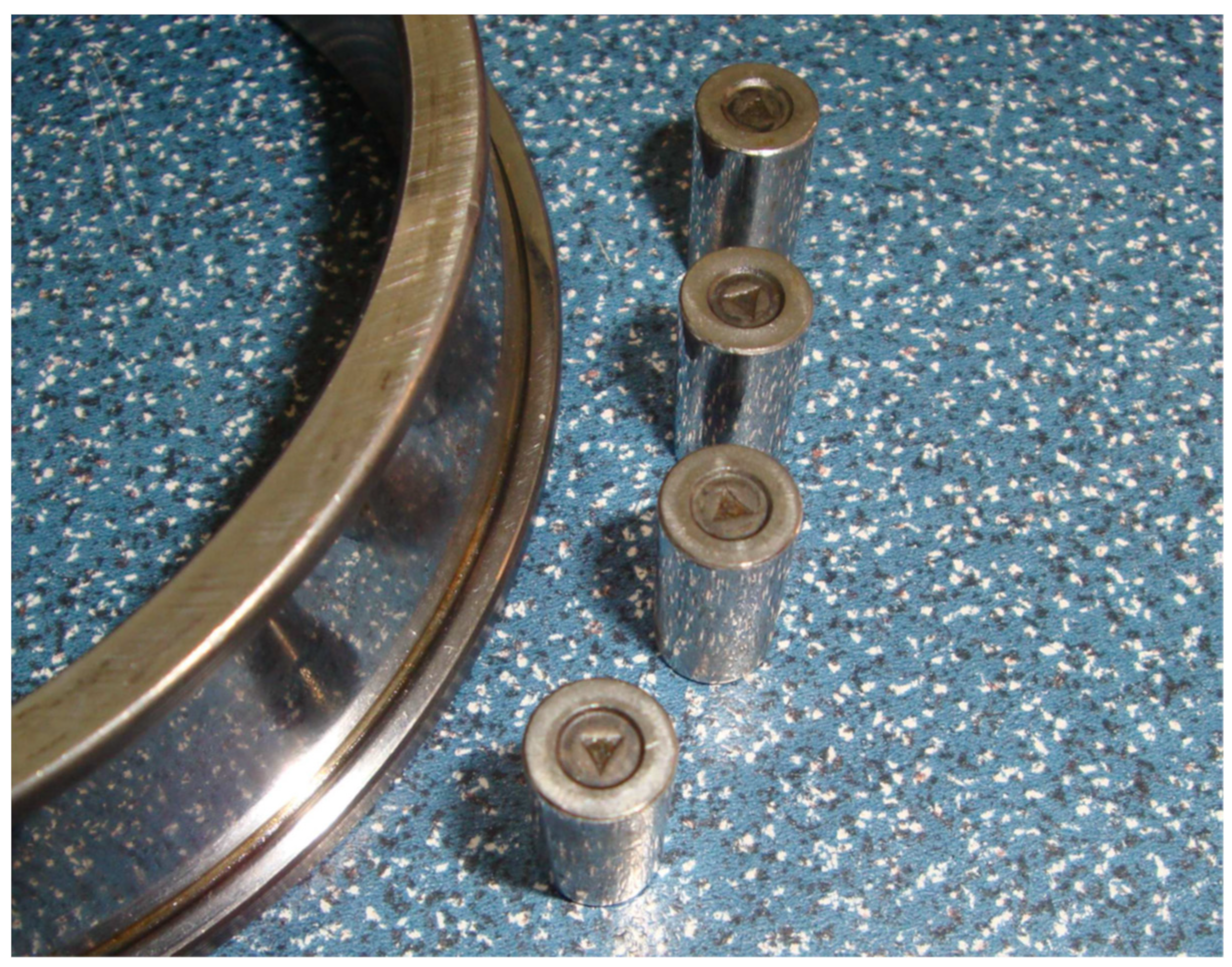
Subsequently, the milling head was disassembled. After disassembly, we analyzed the bearing seating, assessed the condition of the bearings and contact surfaces, performed a lubricant analysis, and then assessed the friction regime.
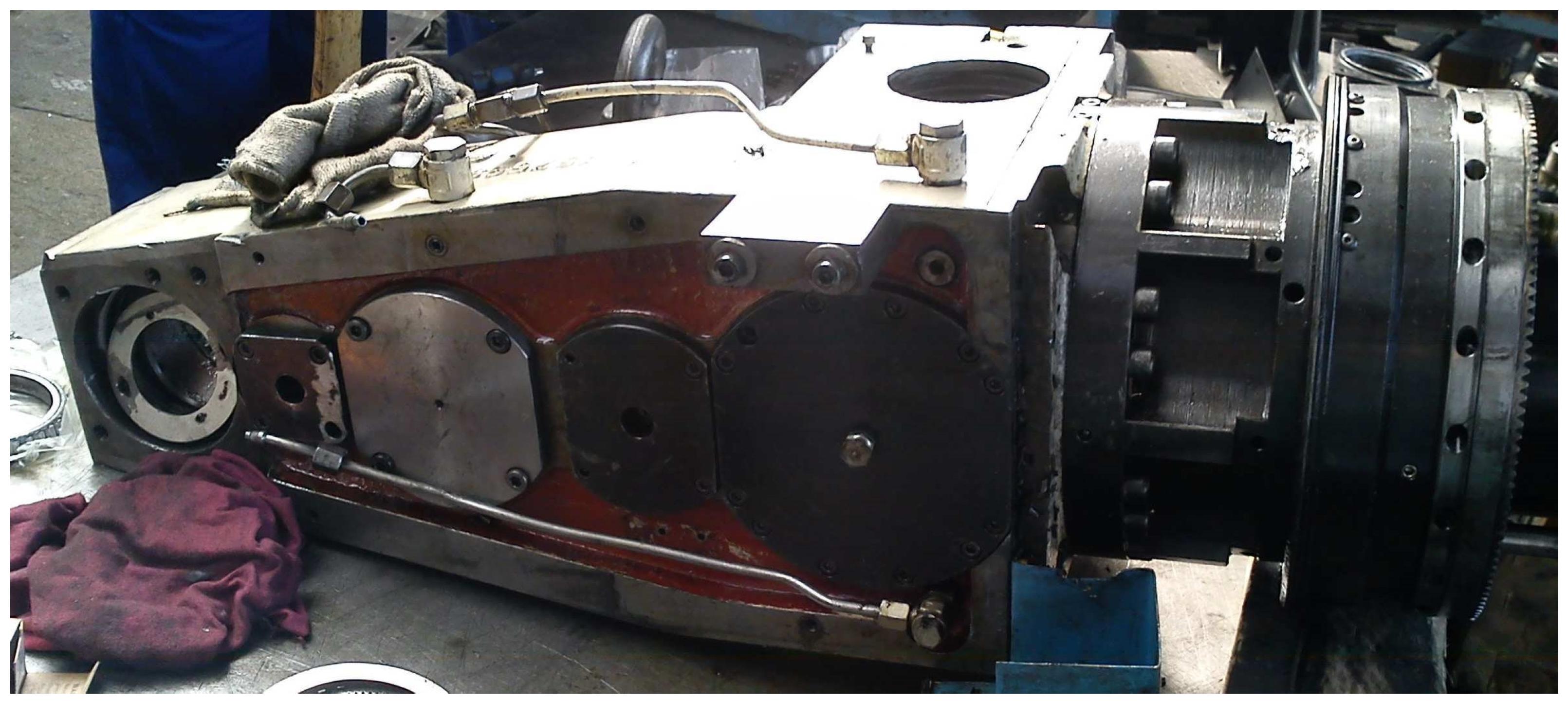
Figure 1 shows the milling head after its disassembly from the machine.
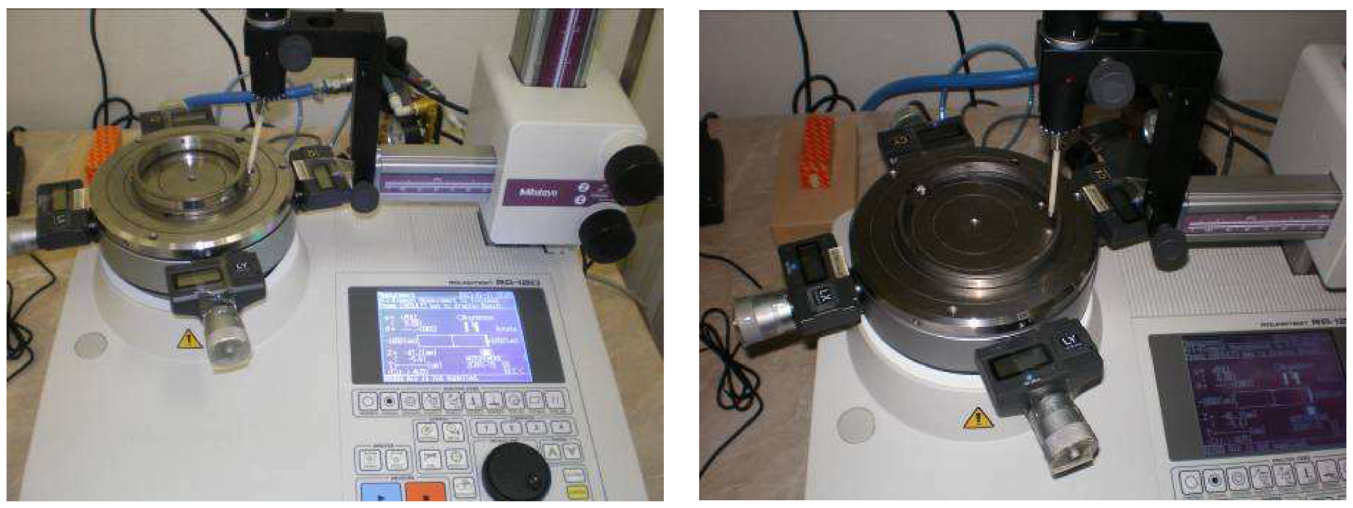
The rolling bearings were further disassembled into individual bearing components while the control microgeometry of selected surfaces (contact surfaces) was carried out. Roundtest RA120 equipment was used for the measurements.
The holder for fixing the cutting tool (milling cutter, drill bit, etc.) is mounted in two tapered roller bearings, type 31312 A, ZVL, and 32314 J2/Q, SKF. The bearings are mounted with an axial preload to increase their rigidity, with the assumption of reducing the cutting tool’s deformation and oscillation from high dynamic excitation and the cutting force during machining.
The primary objective of the conducted research was to comprehensively examine the operational issues of the CNC machining center, which include assessing risks such as low bearing lifespan, increased bearing clearance, heightened vibration levels, and qualitative deficiencies in machined parts. The purpose of the research within this study was to address these identified problems and propose solutions to enhance the performance and overall reliability of the monitored equipment. New insights and contributions to the respective field emerged from the thorough analysis, which involved vibration measurements and evaluation of various factors that helped identify potential issues with bearing seating and friction regime.
3. Vibrodiagnostics of the Rolling Bearings in the Milling Head Bearing Seating
Vibration measurements were conducted following the above description provided by the plant operator. In the framework of applied vibrodiagnostics, the methods used were as follows:
VEL (Deflection Velocity):
VEL measures the rate of deflection, which is the amplitude gain per unit of time. The deflection rate provides information about the dynamic motion of the system’s elements and obtains an overall picture of the vibration over a range of frequencies.
ACC (Deflection Acceleration):
ACC measures the acceleration of the deflection, i.e., the rate of change of speed. Acceleration is often important for identifying sharp and short-term changes in vibration. This method can be effective in detecting sudden disturbances or irregularities.
EN2 (Second Envelope—50 Hz to 1 kHz):
ThisI confirm. is an analysis of the signal in the frequency band from 50 Hz to 1 kHz, which may be relevant for identifying vibrations associated with machine speed, gear teeth, and other components.
EN3 (Third Envelope—500 Hz to 10 kHz):
This method concentrates on higher frequencies (from 500 Hz to 10 kHz), which can be useful in identifying fine details of vibrations, such as high-frequency noises associated with various mechanical processes.
EN4 (Fourth Envelope—5 kHz to 40 kHz):
Frequency band analysis from 5 kHz to 40 kHz. This method focuses on very high frequencies, which can be important in identifying subtle changes in vibration or detecting high-frequency sounds associated with specific disturbances.
Using multiple methods with different frequency ranges offers a more comprehensive vibration analysis at different levels of detail. These methods can help identify irregularities, predict failures, and optimize the operation of CNC equipment. Speed sensors and accelerometers were placed on key parts of the machine, such as the spindle and the cutting tool mounting bracket.
The vibration signal was measured using velocity sensors and accelerometers (Bruel & Kjaer 4393 velocity sensor, PCB Piezotronics 352C22 accelerometer). These sensors are capable of measuring the velocity and acceleration of displacement, which are key parameters in the analysis of vibrations.
The measurement procedure was as follows:
Sensor Installation: The sensors were firmly and stably attached to the spindle to prevent them from shifting or falling off during measurement and operation of the equipment. The vertical placement of the sensors in the radial direction to the axis of rotation of the spindle is ideal for capturing vibrations that occur in the direction of rotation of the rotor. This placement allows the sensors to accurately measure the velocity and acceleration of displacement, which are key parameters in the analysis of vibrations.
Data Recording: After installing the sensors, vibration data were recorded in real time during the operation of the CNC machine (idle run). These data were recorded in digital format for further analysis. By measuring vibrations in the idle state, it is possible to identify basic vibrations caused by various factors, such as an imbalance of rotating parts, geometric errors of the spindle or bearings, or even vibrations transmitted from the structure of the machine itself, and distinguish them from vibrations that may be caused by the machining process.
Data Analysis: The recorded data were then transferred to the data recording system for further analysis. The stated methods of vibration analysis were used, including VEL (velocity of displacement), ACC (acceleration of displacement), EN2 (second envelope—50 Hz to 1 kHz), EN3 (third envelope—500 Hz to 10 kHz), and EN4 (fourth envelope—5 kHz to 40 kHz), to identify any irregularities or potential problems using the MATLAB Signal Processing Toolbox software tool (Version 6.11 (R2009a)).
Interpretation of Results: Based on the results of the analysis, potential irregularities and problems were identified. At this stage of measuring and analyzing vibration signals, it is important to compare the measured levels of vibrations with established thresholds or standards to determine if they exceed acceptable limits.
Table 1 contains the measured vibration values. The measurement was performed in the idle state, i.e., no machining was carried out. The measured HF vibration values were well above the Alarm A2 level (see
Table 2).
The recommended limits are set in accordance with STN ISO 10816-3. For different machine operating modes (referring to speed/load/power), limits (alarms) can also be set following a general recommendation, i.e., a signal increase of 200% compared to the reference value.
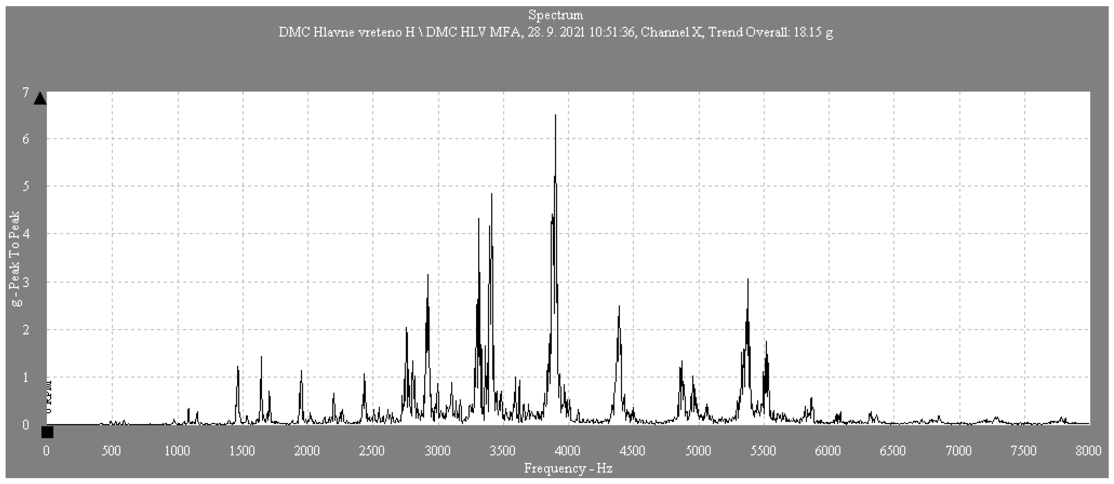
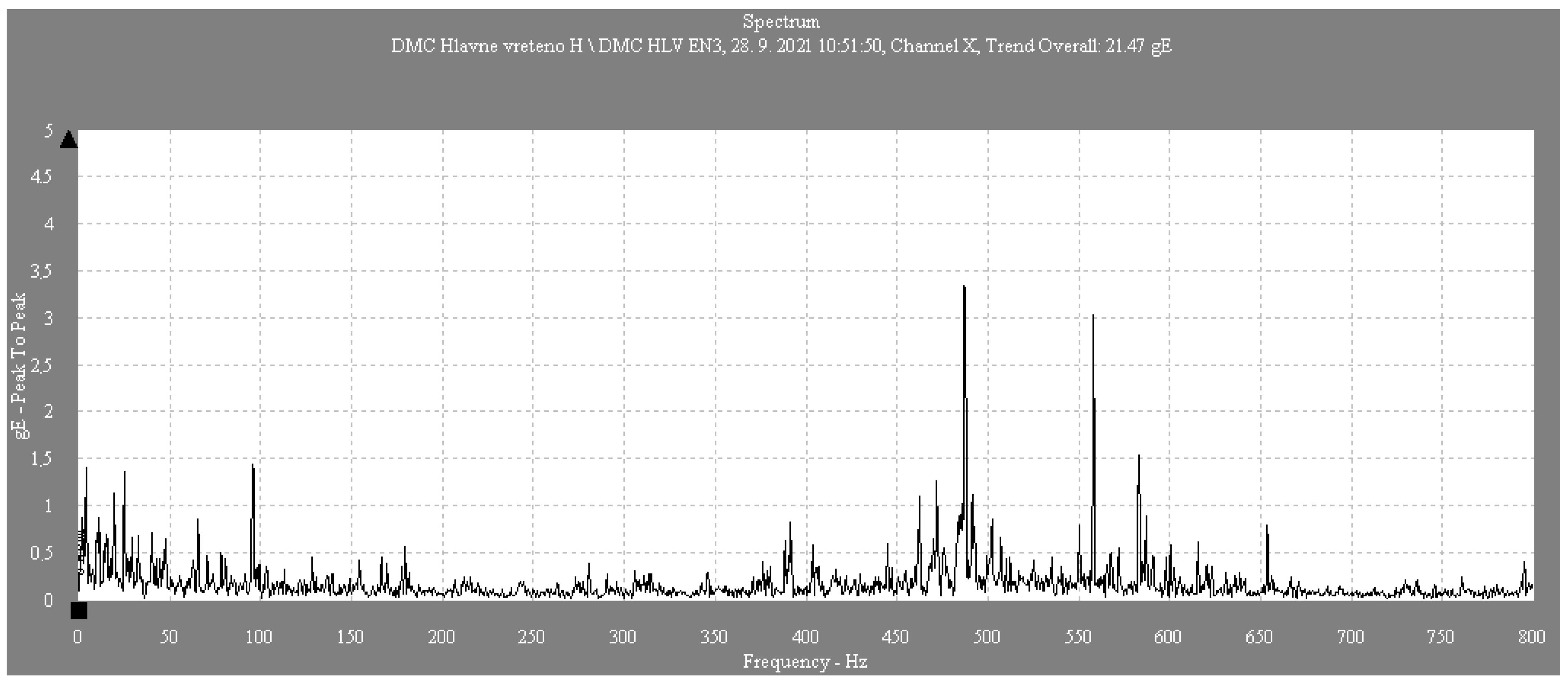
In
Figure 2,
Figure 3 and
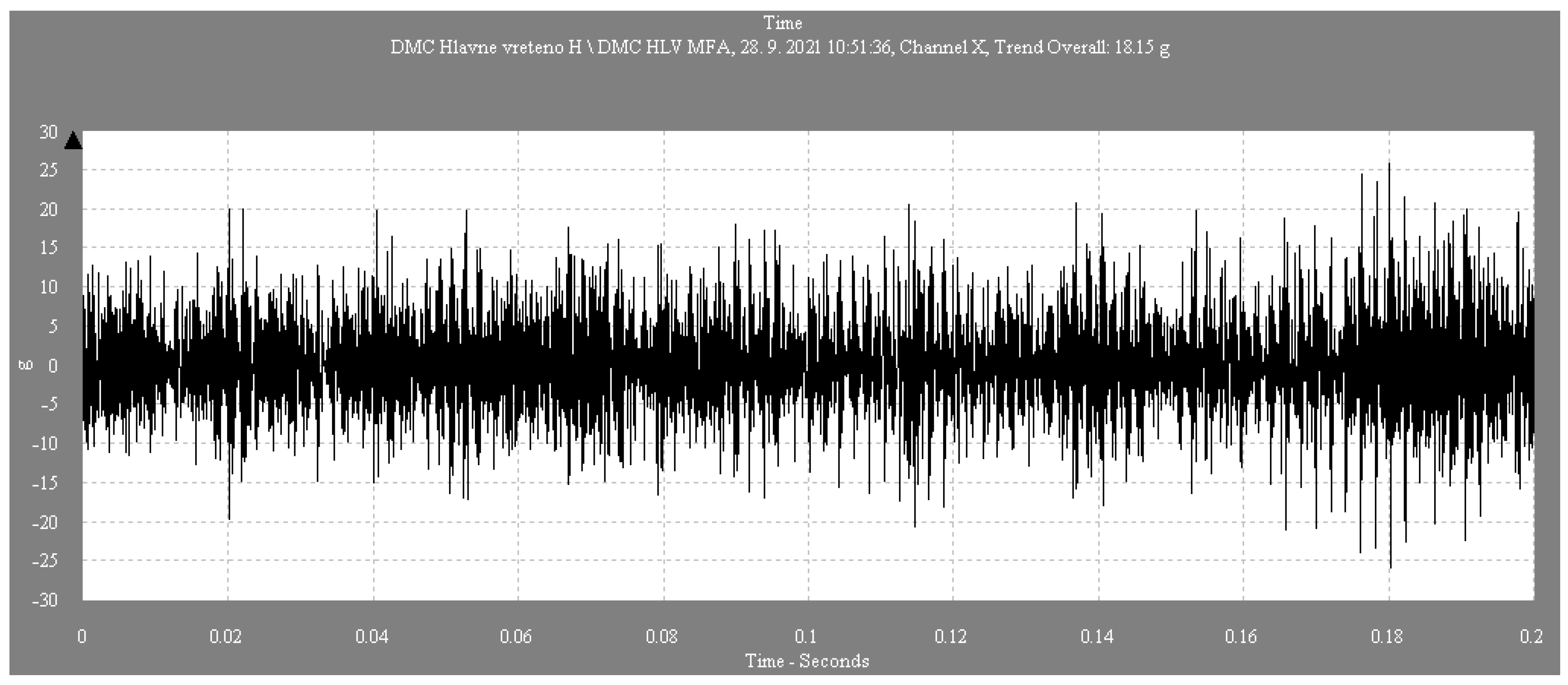
Figure 4, plots for the ACC spectrum in the vertical direction, the EN3 spectrum in the vertical direction, and the ACC time record in the vertical direction are plotted.
Vibration values were measured in individual directions (horizontal, vertical, and axial). Considering the measurement results, it is obvious that there is a significant vibration problem in the system. The measured values exceed the limits of the A2 alarm, which indicates a hazard. Amplitudes reaching values of over 20 g and a frequency of approximately 487 Hz indicate a probable bearing problem. This may result in repairing or replacing bearings on the monitored equipment.
4. Bearing Disassembly, Surface Condition Assessment, and Microgeometry
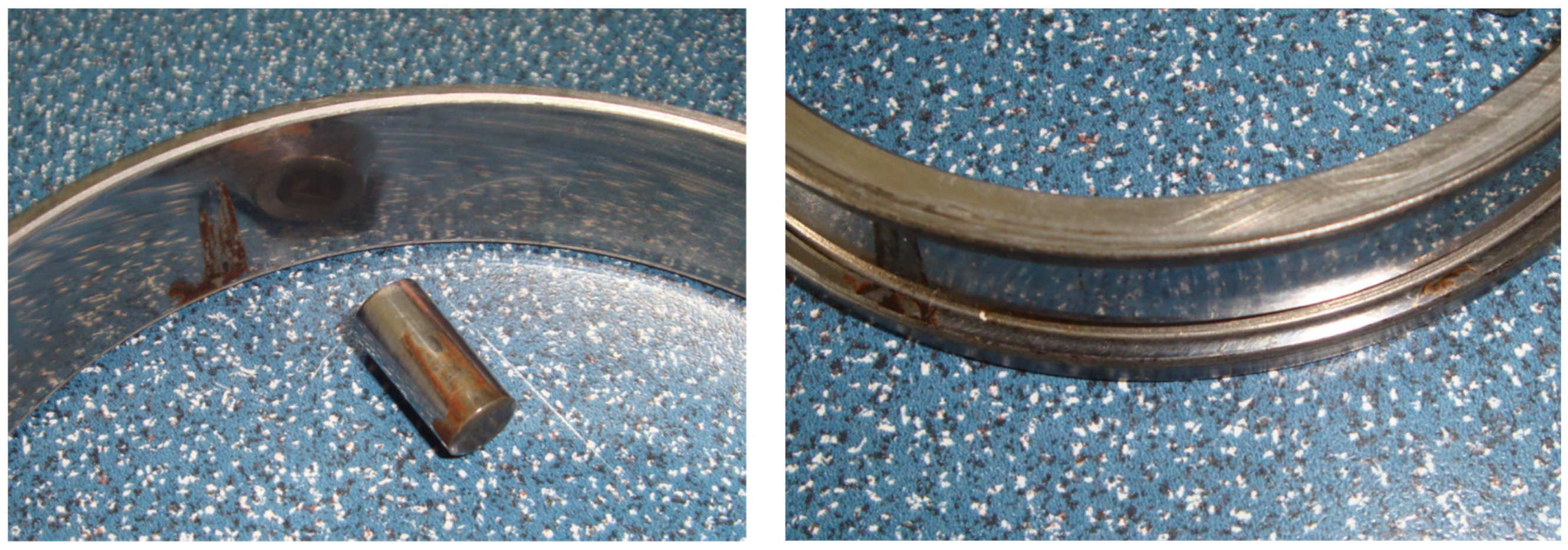
After dismantling the bearings, we visually inspected the rolling elements and inner and outer rings of the bearings under consideration. For lubricating the monitored tapered roller bearings, synthetic universal bearing grease ISOFLEX NBU-15 was applied. ISOFLEX NBU-15 grease is often used in applications with high loads, high speeds, and operating temperatures, where high stability and protection against wear are required. There is a distinct abrasive abrasion on the faces of the rolling elements as well as on the support face of the inner ring, i.e., a run-in mark at the point of contact (
Figure 5). The wear (loss of material) on these surfaces is directly related to the decrease in axial preload set when the bearings were mounted.
Local surface corrosion is visible on both the rolling element housing and the outer ring orbit (
Figure 6). This is a typical sign of penetration of the cutting emulsion (and its component, water) into the bearing seating area and the grease lubricant. Corrosion can cause bearing wear and lead to earlier bearing failure. Weaker surface integrity can increase friction and heat production, accelerating rolling element wear. Corrosion can also impair the lubrication efficiency of the bearing, as the damaged surface may have difficulty retaining the lubricant and releasing it evenly. Finally, yet importantly, corrosion can cause deformation of the rolling element or outer ring, which reduces the overall accuracy and stiffness of the bearing.
Corrosion on the rolling element housing and the bearing outer ring orbit can seriously impact the bearing’s reliability and service life. It can be caused by various factors, such as moisture, aggressive environments, chemicals, or mechanical damage to the protective layer on the bearing surface. We attempted to identify the causes of the resulting diet by performing subsequent analyses.
5. Assessment of the Condition of the Applied Lubricant and Friction Regime
A grease lubricant sample was collected and analyzed during the dismantling of the bearings. Rolling bearings must be lubricated to achieve their highest possible service life. Considering the signs of damage to the bearing contact surfaces (all orbits, wear, abrasion), we detected the presence of the particles in the lubricant samples as follows:
The lubricant prevents direct contact between the rolling elements, the orbits, and the cage. This ensures low friction and low wear. Lubrication also has the function of dissipating the heat generated by rolling contact. This maintains a stable operating temperature of the bearing, which is important for its service life. The lubricant helps reduce frictional losses in the bearing (i.e., the loss of energy released in the form of heat due to friction in the bearing itself). These losses occur during rolling contact in the bearing, where the rolling elements come into contact with the bearing grooves or the inner and outer rings. Friction losses are one of the factors that can affect the efficiency and temperature of the bearing, thus minimizing heat generation and improving the operation’s energy efficiency. It can also ensure that the bearing maintains accuracy and stiffness, which is important for applications requiring high precision in force transmission.
Solid impurities in the lubricant are a frequent part of lubricant condition and quality analysis:
Dispersed particles (DL): these are evenly dispersed in the lubricant. They may be microscopic solid particles, metal dust particles, or other dissolved or dispersed substances. These impurities may result from wear, contamination, or processes in the lubricant.
Dispersed sediments (DS): these are usually larger particles that remain suspended in the lubricant but may settle to the bottom or in areas of low flow. The presence of sediments can be a sign of poor lubricant quality or be caused by the degradation and wear of bearings or other components.
Analysis of solid impurities in the lubricant is important for predicting problems with the lubricant or the operating mechanical equipment. For the analysis of applied lubricant, the method of ferrography was employed at the tribology laboratory of the Technical University of Košice. Ferrography is a diagnostic method used to analyze oils and lubricants to detect the presence of metallic impurities and machine component wear. It utilizes a magnetic field to detect and subsequently analyze metallic particles in the lubricant sample. During machine operation, metallic components wear down, releasing small particles into the lubricant. These particles come in various shapes and sizes. Ferrography utilizes the magnetic properties of these particles for identification. An oil sample is placed on a glass slide and exposed to a magnetic field, then analyzed under a microscope. Different shapes and colors of particles can indicate various types of wear or corrosion.
Table 3 shows the values of the measured variables in the applied lubricant ISOFLEX NBU-15 and their comparison with the recommended limits.
As can be seen from the measured values shown in
Table 3, it can be concluded that the number of solid particles, the number of Fe abrasion particles (these are particles generated by the operation of the contact surfaces), as well as the number of corrosive particles (red iron oxide), indicate a non-conforming friction regime and lubricant condition. The grease lubricant sample also contains water from the cutting emulsion.
The plant operator is also required to determine the optimum lubricant temperature, which can affect the magnitude of the friction torque.
Friction depends on the load and several other parameters. The total rolling resistance in a bearing consists of rolling and shear friction at the rolling contact point between the rolling elements and the cage. The total frictional moment is given by the frictional moment, which does not depend on the bearing load (
M0), and the frictional moment, which depends on the bearing load (
M1).
Moment
M0, independent of load, is predominant in less-loaded, high-speed bearings. For speeds of 2000 rpm and above, it is calculated according to the following equation:
For speeds below 2000 rpm, the calculation is as follows:
where:
M0—torque that does not depend on the load [Nmm];
dm—mean bearing diameter = 0.5(d + D) [mm];
f0—a factor that depends on the bearing type and lubrication;
n—bearing speed [min−1];
ν—kinematic viscosity of the lubricant at operating temperature [mm2·s−1].
Periodic lubricant tests may include laboratory methods such as microscopic analysis, gravimetric analysis, or other techniques that allow the presence of solid impurities to be identified and quantified.
The
M1 torque depends on the load and is predominant on lower-speed bearings operating at high loads. It is calculated based on the following relation:
where:
M1—load dependent torque [Nmm];
f1—coefficient dependent on bearing type and load;
P1—load component, decisive for the size of the friction torque [N];
dm—mean bearing diameter = 0.5(d + D) [mm];
a, b—exponents dependent on the bearing type.
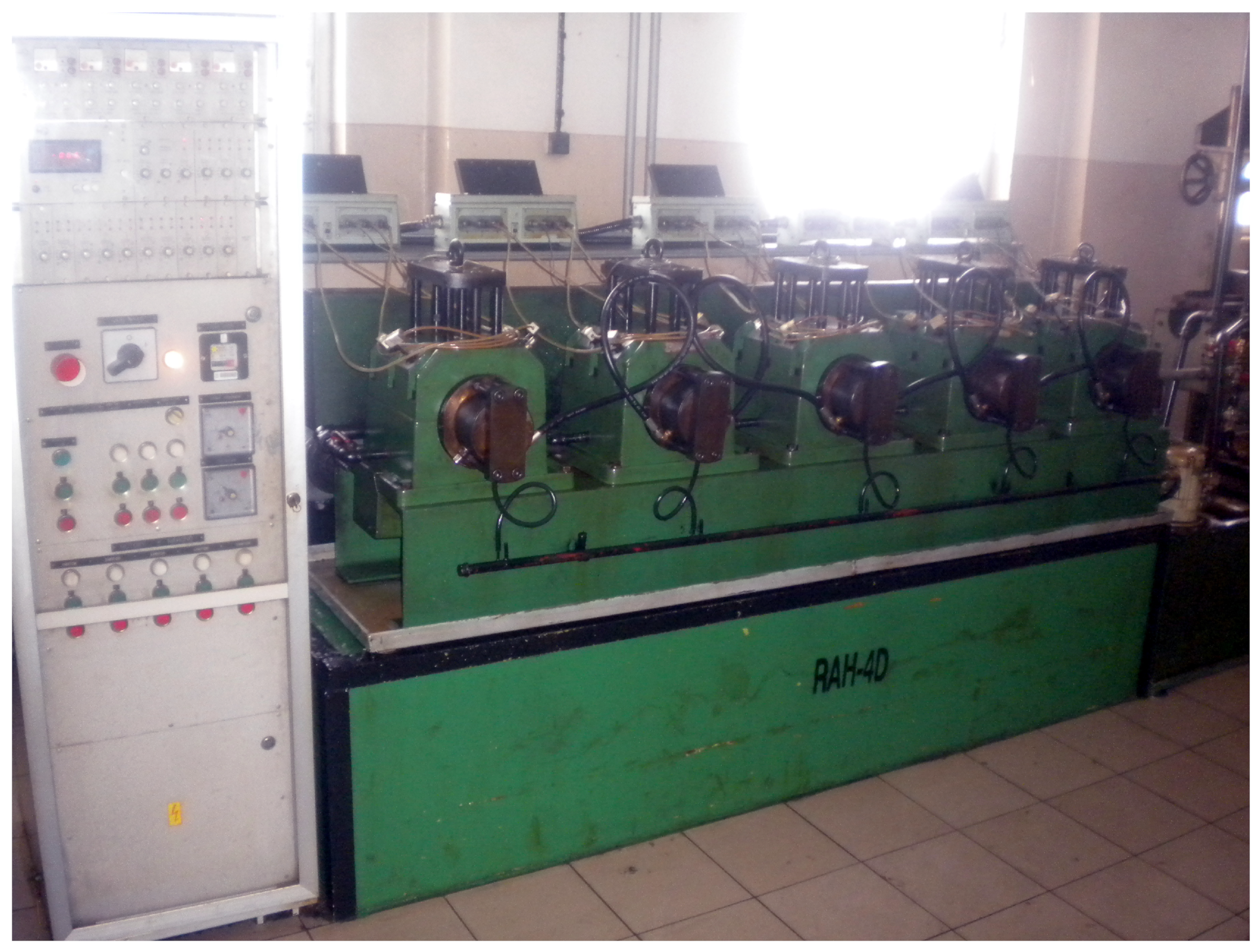
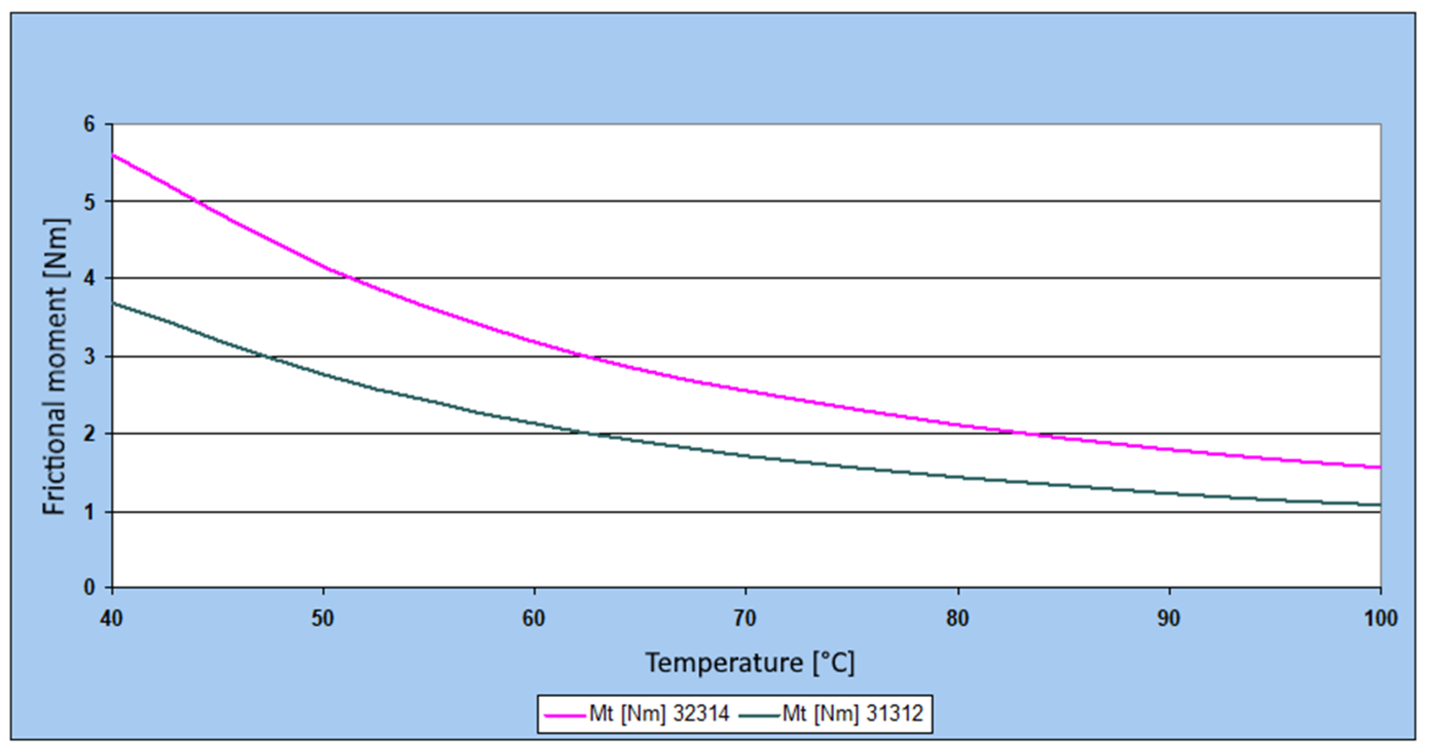
Bearings 32314 and 31312 were used in the experiment. The results are shown in
Table 4. We conducted the measurements in laboratory conditions using the testing station RAH-4D (see
Figure 7).
The RAH-4D represents a system used for testing the lifespan of radial bearings. The objectivity and reproducibility of the tests are ensured by automatic operation, which is facilitated by automatic measurement and control of the temperature of the tested bearings. In addition to basic testing methods (vibrations, temperature, speed, and long-term operation monitoring), this system allows monitoring of approximately 65 measured parameters, including the friction torque, lubricant leakage tests, and seal tests for covered bearings. Temperatures are continuously recorded. Control systems shut down the drive of the tested bearings if the set temperature measured in the space of the outer rings of the bearings is exceeded, or in the case of a sudden increase in the temperature of the lubricating oil, as well as in the case of a significant increase in vibration levels—especially in the case of the fatigue process pitting—and in the case of a malfunction of the hydraulic system. The measurement was conducted according to the methodology valid for the given test equipment. The bearings are mounted on the shaft of the test machine opposite each other. Similarly to how the bearings are lubricated in the specific equipment, the bearings in the bearing test stand are lubricated as well. The temperature measurement methodology (innovated for ZKL) is based on measuring the temperature of the oil lubricating the bearings. This temperature data from each shaft separately is displayed on the control panel of the test machine (see
Figure 7). The determination of the kinematic viscosity of the lubricant used at different temperatures was carried out in the tribology laboratory of the Technical University of Košice in accordance with the standard STN EN ISO 3104 (65 6216).
The basic parameters of bearings are as follows:
Bearing 32314 Bearing 31312
d = 70 mm d = 60 mm
D = 150 mm D = 130 mm
The table and graph (
Figure 8) show that as the temperature increases, the frictional moment decreases, which is closely related to the kinematic viscosity value. In this case, it is advisable to keep the bearing temperature at approximately 90 to 100 °C.
Generally, the maximum operating temperature of a bearing depends on the bearing material, type of lubricant, and specific operating conditions. For standard rolling bearings, the recommended maximum operating temperature typically ranges between 120 °C and 200 °C. [
30] At higher temperatures, it is necessary to use special lubricants or bearings designed to work under such conditions.
It is important to note that any increase in temperature above the normal operating temperature can shorten the bearing’s lifespan. Therefore, it is crucial to ensure that the bearing temperature does not exceed the values recommended by the manufacturers and that an adequate lubrication scheme and cooling system are provided to prevent bearing overheating.
6. Analysis of the Microgeometry of Bearings Disassembled from the Milling Head Seating
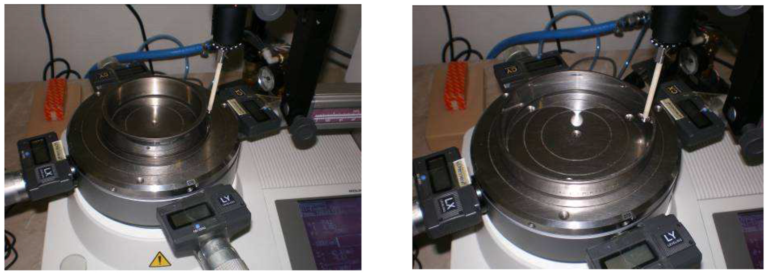
After disassembling the bearings into individual bearing parts, the microgeometry of selected areas of the contact surfaces was inspected. Roundtest RA120 equipment was used for the measurement.
Figure 9 and
Figure 10 show the measurement of the individual bearing parts, measuring the roundness of the orbits of the inner and outer rings.
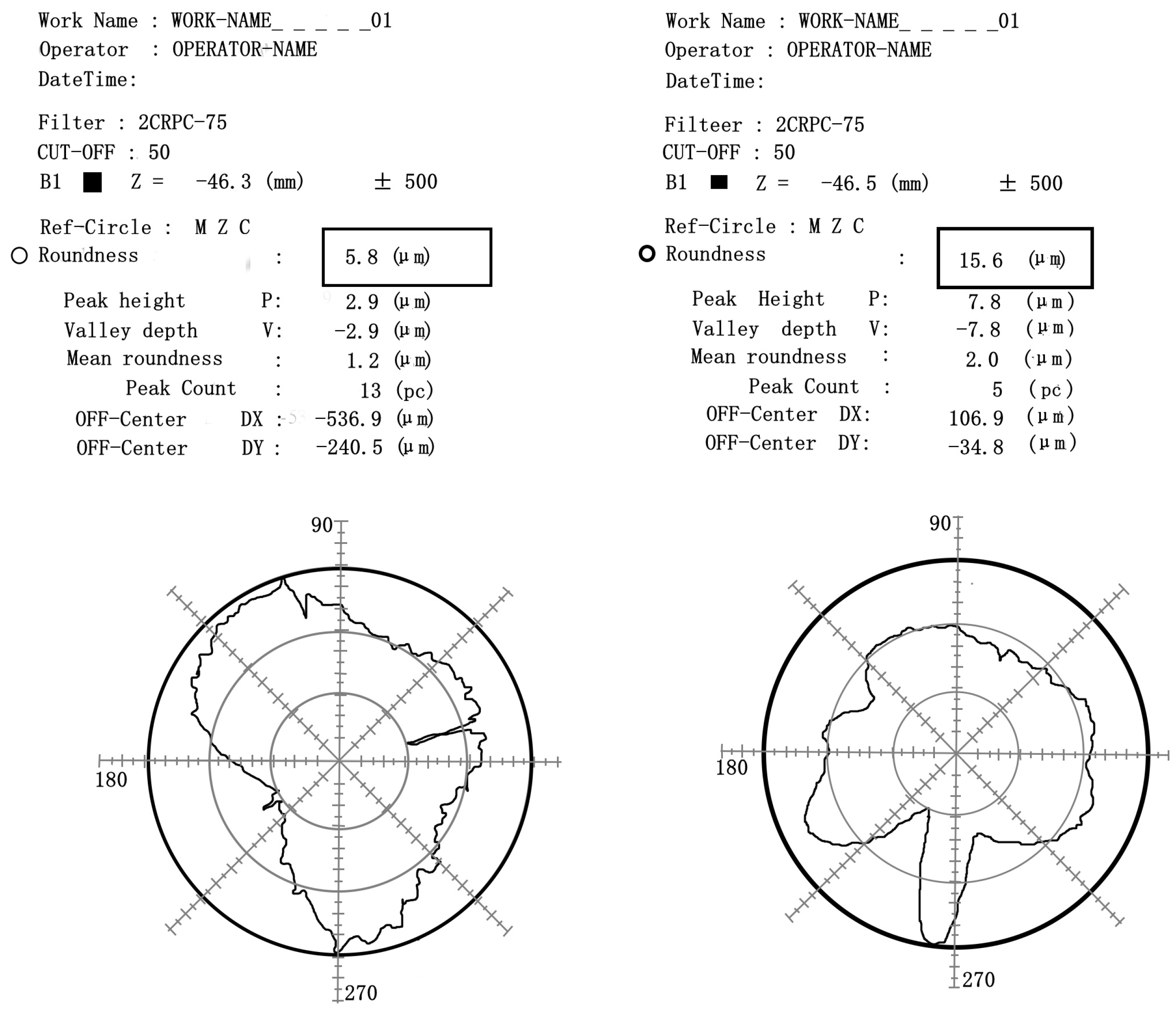
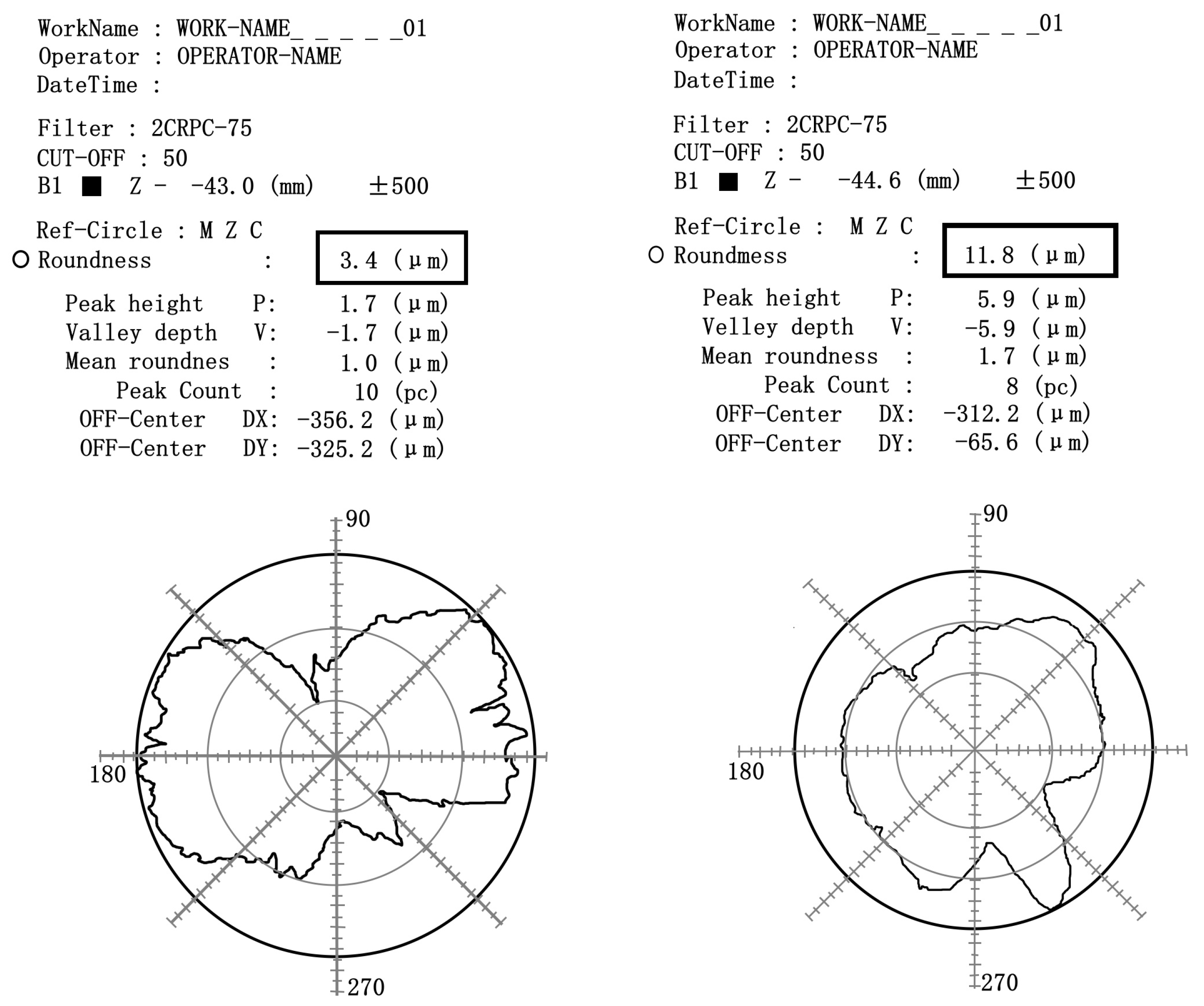
Figure 11 and
Figure 12 show the measurement results from the Roundtest RA120 in the form of a graphical visualization for understanding the shape and deviations. The output can contain information about the radial and axial waveforms of the measured component. This includes changes in shape and surfaces in different directions. Any irregularities or deviations from the ideal circular shape can be identified when measuring circularity.
Three measurements of circularity were conducted on the outer ring of the monitored bearings, with a uniform distribution around the circumference of the rings. Similarly, in the case of the circularity measurement on the running tracks of the inner ring, three measurements were performed to ensure sufficient accuracy and reliability of the results. The accuracy of circularity measurement with the metrological device used can range from several microns (µm) to tens of microns. The specific value depends not only on the calibration and setting of the device but also on adherence to correct measurement procedures and the level of damage to the bearing. During circularity measurement on the running tracks of the inner and outer ring of the bearing using the Roundtest RA120 device, the measurement range in the
Z-axis was set to ±500 µm (see
Figure 10 and
Figure 11). This range allows for capturing movements and deviations in circularity on the given axis with sufficient precision.
The individual parts’ roundness records confirmed that the roundness requirement for the outer and inner rings is unsatisfactory when following the recommendation for reliable operation. The measured roundness values confirm unsuitable operating conditions. The penetration of the cutting emulsion into the bearing seating area and the grease limits the functionality of the applied lubricant when it does not perform its role optimally. As a consequence, the circularity of the bearing ring orbits is also impaired. This condition applies to both bearings under investigation. For this reason, the function of the bearings under consideration is limited as a result.
7. Assembly of Tapered Roller Bearings with Axial Preload
Ensuring the correct axial preload is key to achieving optimum results and the long life of tapered roller bearings, especially in applications with high precision and reliability.
Axial preload helps eliminate the gap between the roller and the bearing groove. This ensures the bearing is firmly and accurately positioned, reducing vibration and unwanted cylinder movement. This is important for stable and quiet bearing operation. It also contributes to increased accuracy of bearing operation. This is significant in applications requiring high positional accuracy and minimal misalignment. Properly adjusted axial preload contributes to increased bearing stiffness, which is required in operations under severe load conditions where emphasis is placed on minimum deformation and maintaining bearing integrity. Axial preload can help prevent axial overload of the bearing. Finally, proper axial preload can help minimize heat generation in the bearing. Maintaining an optimum operating temperature and avoiding excessive heating help increase bearing life.
The reasons for assembling tapered roller bearings with axial preload are as follows:
Increase in rigidity of the fit (less deformation–displacement under load, mainly axial or dynamic); reduction in vibrations and noise;
Increase in running accuracy (radial and axial throw);
Compensation of running-in processes (settling of bearings during initial operation);
Increased bearing life.
When determining the preload, the preload force must first be calculated to ensure the optimum combination of bearing stiffness, life, and reliability. Next, the preload force to be used in aligning the bearings during assembly is calculated. During assembly, the bearings should be at ambient temperature and not subjected to any other load.
The correct preload at a normal operating temperature depends on the bearing load. Angular contact ball bearings and tapered roller bearings can integrate radial and thrust loads simultaneously. When radial loads are applied, these bearings generate a force in the axial direction, which must be absorbed by a second bearing located in the opposite direction to the first bearing. The close radial displacement of one bearing ring relative to the other means that half of the rolling elements are loaded [
31].
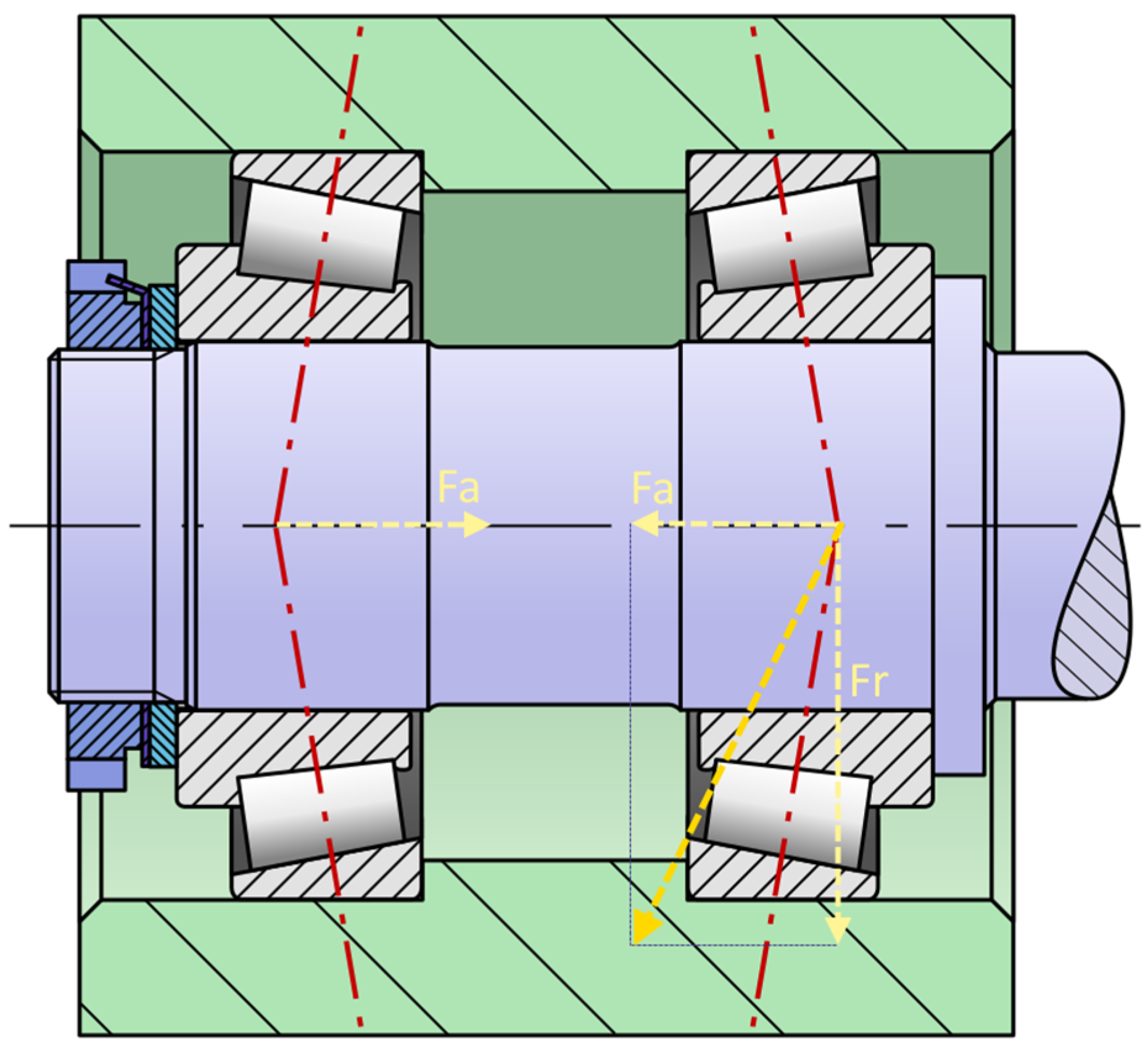
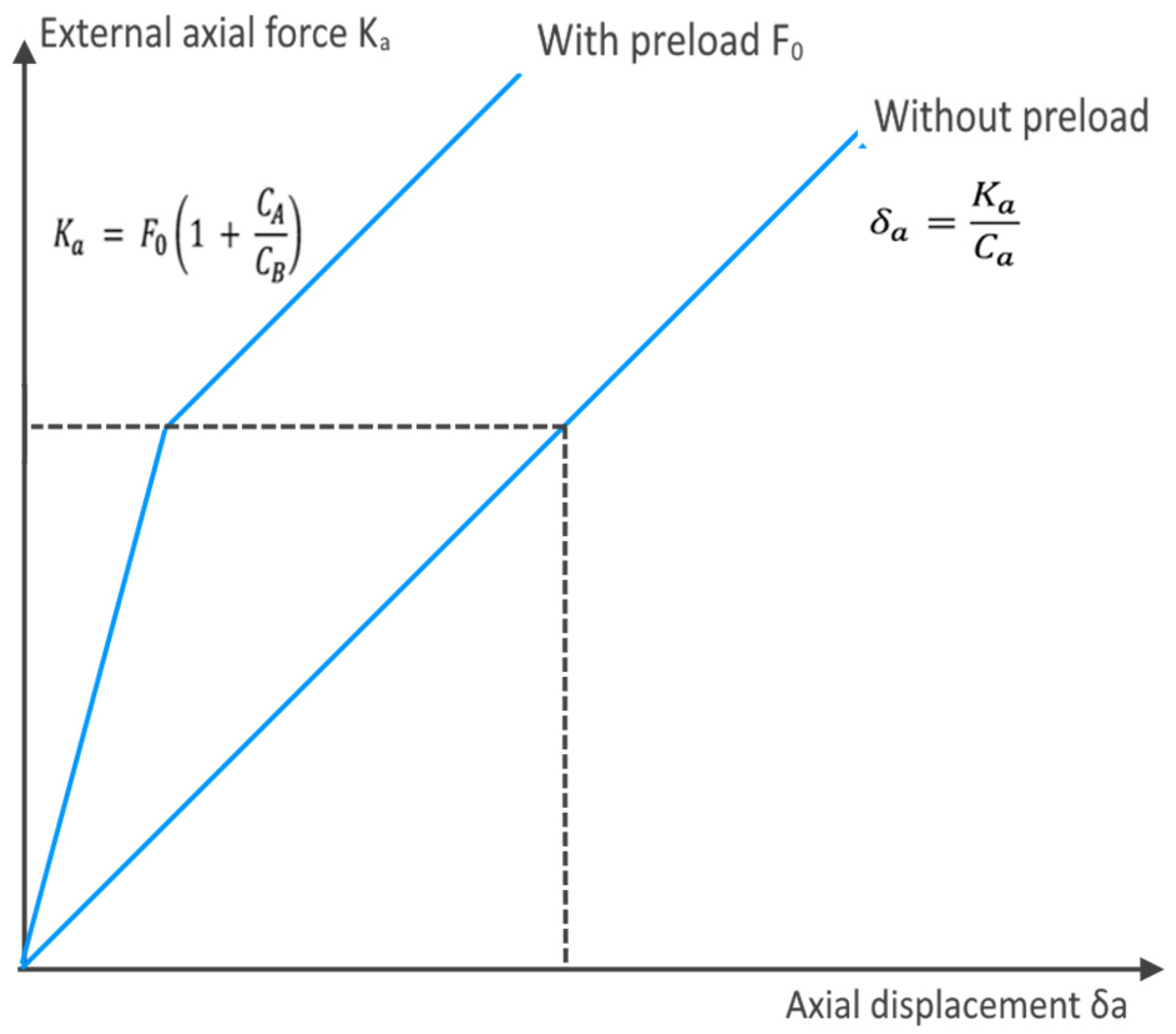
Therefore, in the case of a single bearing loaded with a radial force Fr, an external axial force Fa of the same magnitude as the axial force generated in the bearing must be used to fully utilize the bearing’s basic load capacity (
Figure 13). If the applied external force is lower, the number of rolling elements carrying the load will be lower, and the load capacity will be reduced accordingly.
In a bearing arrangement consisting of two single-row angular contact spherical roller bearings or two single-row tapered roller bearings arranged back-to-back or tapered, each bearing shall absorb the axial load in one direction. If these bearings are set at a clearance close to zero, the radial load is equally distributed between the two bearings, and half of the rolling elements in each bearing are loaded.
In other cases where an external axial force is present, bearing preload may be required to compensate for the clearance created by the elastic deformation of the bearing absorbing the axial load. Preload also produces a more favorable load distribution in an axially balanced bearing.
Figure 14 shows the dependence between axial load and deformation-displacement. In the case of an axial preload assembly, the displacement is significantly eliminated.
The graph in
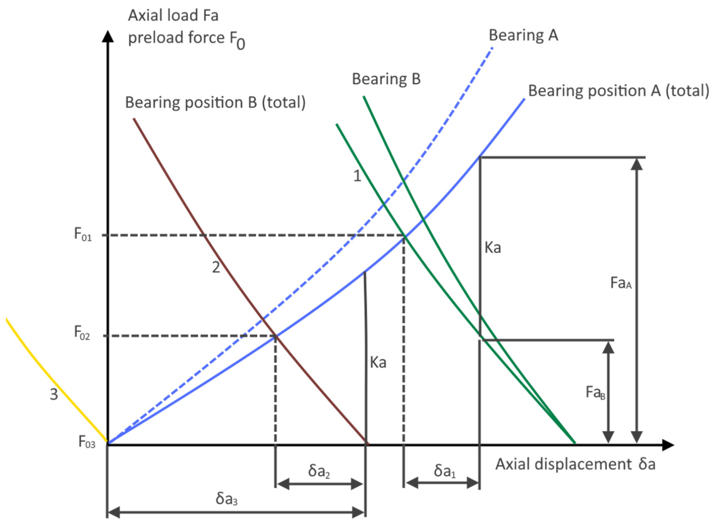
Figure 15 shows the change in bearing position due to axial displacement. The magnitude of the change in position is important for the following reasons:
From diagram (
Figure 15), we can further understand the interplay between components, such as in the design of a pinion arrangement, where bearing A is positioned adjacent to a gear and is set against bearing B to achieve preload. The external axial force, denoted as Ka (the axial component of tooth forces), acts in conjunction with the preload force F
01 (curve 1) in a manner that adds additional load to bearing A while reducing the load on bearing B. The axial load on bearing A is denoted as Fa
A, and on bearing B, it’s denoted as Fa
B. Due to the influence of the axial force Ka, the pinion shaft is displaced axially by an amount represented as δa
1. A smaller preload force, denoted as F
02 (curve 2), is selected to ensure that bearing B is precisely relieved of the axial force Ka, resulting in Fa
B = 0 and Fa
A = Ka. In this scenario, the pinion shaft experiences a displacement represented by δa
2, where δa
2 > δa
1. Conversely, in the absence of preload (curve 3), the axial displacement of the pinion shaft reaches its maximum value (δa
3 > δa
2).
Preload also increases the stiffness of the bearing arrangement. However, it should be remembered that the stiffness also depends on the elasticity of the shaft and housing, the seating of the bearing rings on the shaft and in the housing, and the elastic deformation of all components adjacent to the bearings, including axial protrusions. All these factors significantly influence the elasticity of the entire bearing system. The axial and radial reverse elasticity of a bearing depends on its internal design, the conditions of contact of the rolling elements with the orbits (point or line contact), the number and diameter of the rolling elements, and the contact angle. The larger the contact angle, the greater the bearing stiffness in the axial direction [
31].
Preloaded bearings provide more precise shaft guidance because the preload increases the degree of stiffness, reducing the shaft’s tendency to deflect under load. For example, preloading in a differential gear pinion bearing increases stiffness, ensuring accurate and consistent gear engagement. As a result, dynamic forces are kept to a minimum and noise levels are reduced, which can extend gear life. Wear and settlement processes in the bearing arrangement increase backlash during operation. Preload compensates for this increase in backlash.
In specific applications, bearing arrangements with optimum preload can improve operational reliability by providing a more favorable bearing load distribution and extending bearing life.
When selecting the preload for a given bearing arrangement, it must be remembered that once the optimum preload value is exceeded, the stiffness will increase only slightly. Exceeding the optimum value increases friction and, consequently, the amount of heat generated, which can significantly shorten bearing life and negate all the benefits of preload. Too high a preload adversely affects the operational reliability of the bearing arrangement.
When adjusting the preload in a bearing arrangement, it is also important that the preload value determined, calculated, or selected by the experiment is obtained with as little variance as possible. To reduce the spread, for example, when mounting tapered roller bearings, the shaft should be rotated several times if possible so that the rollers do not become angled and their ends are correctly aligned with the guide flange of the inner ring. Rotating the shaft also allows the rollers to be in full contact with the outer ring and prevents damage to the orbit. A much lower preload than required will be achieved if the rollers are not in the correct position. Roller bearings should not be run unloaded or accelerated to high speeds in too short a time, as this creates a risk of slippage between the rolling elements and the orbits, which can damage the orbits and cause unacceptably high cage loads [
31].
As mentioned, the bearing’s axial preload and friction depend on each other. Friction increases as the preload increases. To adjust the preload, measuring the friction of a pair of assembled bearings is recommended. Then, increase the bearing preload during assembly until the prescribed friction torque is reached.
However, it is necessary to draw attention to the fact that the frictional moment of the bearings undergoes the following:
It varies for individual bearings (the bearing manufacturer specifies the variance);
It varies depending on the lubrication conditions (preservatives, oil, lubricant, etc.);
It depends on the bearing speed.
For mounting the milling head in a pair of used tapered roller bearings type 31312 A, ZVL, and 32314 J2/Q, SKF, we recommend mounting bearings with axial preload in the range of 1.5 to 2.5 Nm.
8. Discussion of Measurement Results and Assessment of the Observed Correlation
The present study was conducted due to identified problems with the operation of the milling head of the CNC machining center, including low bearing life, increased bearing clearance, high vibration, and quality deficiencies of the machined parts. Following the analysis, vibration measurements, and the above factors, potential problems in the bearing seating and friction regime were identified.
Vibrodiagnostics of rolling bearings
The vibrodiagnostic results indicated significant problems in the system. We measured vibration values exceeding the alarm limits, indicating danger. Amplitudes reaching values of over 20 g and a frequency of approximately 487 Hz indicate a potential bearing problem.
Bearing condition assessment after disassembly and microgeometry
Analysis of the applied lubricant confirmed an unsatisfactory friction regime and the content of abrasive, steel, and corrosive particles. The grease lubricant sample contained water from the cutting emulsion. Such a lubricant condition can increase friction and substantially shorten bearing life. Microgeometry measurements confirmed the unsuitable operating conditions. The roundness of the outer and inner rings did not meet the recommendations for reliable operation. Penetration of cutting emulsion into the bearing housing space and lubricant adversely affected their functionality and roundness.
Assembly of tapered roller bearings with axial preload
The axial preload of the bearings was identified as a key factor for ensuring the optimum operation of the bearing arrangement under investigation. Proper preload increases bearing stiffness, minimizes vibration, and contributes to longer bearing life. Improperly adjusted preload can cause undesirable consequences, including excessive friction and increased heat generation.
The measurements and analysis confirmed a clear correlation between the monitored parameters (lubricant condition-friction regime, abrasion, and abrasion particles–axial preload and bearing stiffness) and the durability (reliability) of the bearings in the milling head housing. This further emphasizes the importance of the correct axial preload for optimum bearing function.
Based on the knowledge gained, we recommend that the operator of the facility perform the following:
Measurement and analysis of the dynamic signal on the milling head, both idle and during machining, in the state after the installation of new bearings and after 3 months of regular operation (in order to monitor the increase in oscillation and possible deformations during machining);
Trend analysis, bearing condition monitoring, and dynamic signal changes over time;
Testing of a new generation of special lubricant designed for lubrication of spindle bearings in an environment with water penetration of the cutting emulsion into the bearing space;
Ensuring that bearings are relubricated and lubricant is renewed at intervals of 14 days to comply with the recommended limits in
Table 1.
Regular maintenance and inspection are crucial to maintaining the optimum condition of the milling head and extending its bearing life. Water ingress into the bearing housing of the milling head can result in several adverse effects on the tapered roller bearings. If the water contains corrosive substances, it can cause corrosion of the bearing surfaces. This can lead to wear and a shortened bearing life. Water can also rinse the lubricant from the bearings, leading to a lack of lubricant and increased friction. This, in turn, causes overheating and wear of the bearings. The cooling system’s efficiency, which is designed to maintain the optimum operating temperature of the bearings, is reduced. Increased temperatures can adversely affect bearing life. It is a fact that water ingress into the bearing housing can make the bearings more susceptible to wear, leading to earlier bearing failure.
In the result, the correlation between the monitored parameters of microgeometry, the analysis of the applied lubricant, the measurement of the dynamic signal during machine operation, and the subsequent correlation with the durability of the bearings in the milling head housing were confirmed.
9. Conclusions
The conducted study provides a thorough insight into the bearing seating problems of the milling head and recommends the necessary steps to improve its condition and the equipment’s overall reliability. Combined methods of analysis, vibration measurements, and bearing condition assessment were applied and subsequently used to identify problems in the operation of the milling head and propose solutions to improve the operation and life of the bearings. Vibrodiagnostics, lubricant analysis, and microgeometry are various methods used in engineering diagnostics to assess the condition of mechanical systems. Each of these methods focuses on certain aspects and provides unique information about the condition of the equipment. Through vibrodiagnostics, problem locations in the mechanical system have been localized. The data obtained through vibrodiagnostics help to optimize the plan for further maintenance. This can be planned based on the actual needs of the system, reducing unnecessary and costly tasks. Early detection of problems in mechanical systems allows repairs to be carried out before a major fault occurs. This helps to extend component life and reduces repair costs.
The applied lubricant analysis used tribotechnical analysis to determine the quality and condition of the lubricant when impurities (abrasive, steel, and corrosive particles) were identified and the friction regime was evaluated. This diagnostics revealed information on the lubricant’s ability to protect the bearings and ensure their required service life.
To confirm the unsuitable operating conditions of the milling head bearings under study, we used microgeometry measurements followed by an assessment of the accuracy of the shape and dimensions of the surfaces of the functional parts of the bearings, such as the circularity of the outer and inner rings. The information provided confirmed the current state of integrity of the bearings and their microgeometry.
In the field of technical diagnostics of CNC machining machines, there are several potential benefits that could arise from the implementation of the proposed approach. These benefits include the following:
A better understanding of failure causes: vibrodiagnostics enables the identification of specific issues, such as excessive vibrations and inadequate lubrication, which can lead to early bearing failure.
Increased machine reliability: regular measurement and analysis of dynamic signals can help identify problems before they lead to serious malfunctions, thereby increasing overall machine reliability.
Extension of component lifespan: using special lubricants and regular lubricant replenishment can reduce friction and wear, thereby extending the lifespan of bearings and other critical components.
Maintenance optimization: trend analysis and monitoring of bearing conditions enable better maintenance planning and interventions, resulting in more efficient resource utilization and reduced repair costs.
Enhancement of product quality: more precise adjustment and maintenance of bearing axial preload can reduce vibrations and improve machining accuracy, leading to higher quality final products.
Prevention of corrosion and other damage: protection against the ingress of water and corrosive substances into the bearing housing can prevent corrosion and premature component failure.
Cost reduction: preventing problems and prolonging component lifespans reduces overall repair and replacement costs.
These benefits align with modern trends in maintenance and diagnostics, which focus on predictive and proactive maintenance based on the actual condition of machines and their components.
In short, vibrodiagnostics focuses on system dynamics through vibration measurements; lubricant analysis focuses on the quality and condition of lubricants; and microgeometry measurements evaluate the accuracy of the shape and dimensions of bearing surfaces. These complementary methods allow an overall view of the mechanical system’s state.


