Abstract
Due to the particular structure of the beveloid gear, it cannot be directly hobbed by an ordinary gear hobbing machine. The existing processing method is complex and has a high cost. Therefore, the mass production and industrialization of beveloid gears are limited. To improve the machining efficiency and accuracy of processing beveloid gears, we proposed a hobbing method via the modification of ordinary hobbing machines. At first, we completed the derivation and calculation of the relevant processing parameters of the beveloid gear based on the study of the structural characteristics of the beveloid gear and the principle of hobbing machining. Then, we proposed and designed a beveloid gear hobbing method, and the modification of the ordinary hobbing machine was completed by using a hanging wheel mechanism in synchronous belt type. Finally, we completed the actual hobbing of the beveloid gear, and the feasibility of the proposed method was verified. After that, we analyzed the machining error of the trial-produced beveloid gear; the results showed that the accuracy of the trial-produced beveloid gear met the 6-level standard, which also verified the accuracy of the proposed method.
1. Introduction
Waterway transportation plays a key role in cargo transportation due to its advantages of large volume and low cost [1,2]. Under the trend of economic globalization, global trade volume continues to rise, and higher requirements are put forward for water transportation [3,4,5,6]. Ships are the primary component of transportation for waterway transportation, and the intelligent development and application of ships have become the future development direction and research hotspot [7,8,9,10]. In the ship power system, gears are widely used in transmission components that transmit power and torque, and the performance of gears has a significant impact on the speed, safety, durability, and fuel efficiency of ships [11,12]. As a new type of gear, the beveloid gear has been applied to marine high-speed gearboxes, marine small inclination transmission systems, and marine RV reducers that with special transmission requirements [13,14]. In addition, beveloid gears are also used in aerospace, automotive, robotics, and other fields [15,16]. The machining method of beveloid gear affects its transmission accuracy and dynamic performance directly. The research on the machining method of beveloid gears can improve the processing accuracy and efficiency of beveloid gears. It can also improve the theory and design system of beveloid gears and then promote the industrialization process of beveloid gears and the intelligent development of ships.
Beam A S. proposed the concept of beveloid gears in 1954 [17]. Compared with traditional gears, the addendum modification factor of beveloid gears varies linearly along the tooth-width direction. Adjusting the beveloid gears’ axial position, compensating for axial error, eliminating turning errors, and providing smooth transmission can be accomplished, which ensures normal meshing when wear or mesh clearance occurs. Furthermore, beveloid gears can meet a higher transmission ratio and a more compact structure. They also have better adaptation to complex operating conditions and can reduce system vibration [18,19].
In general, the processing of gears is divided into the forming method and the generating method in principle. Forming methods mainly include the milling method and the grinding method, which is suitable for single-piece or small-batch production of small- and medium-sized gears [20,21,22,23]. Generating methods mainly include the hobbing method, the shaping method, the shaving method, and the honing method, which is suitable for the production of large quantities of gears [24,25,26,27]. The development of computerized numerical control (CNC) machining technology provides new processing methods for gears, especially gears with special structures and high-precision requirements [28,29,30].
Due to the special structure of beveloid gears, it is impossible to process them with traditional machining methods directly. Therefore, researchers have studied the machining method of beveloid gears based on the characteristics of beveloid gears.
In terms of the hobbing of beveloid gears, Shen Y proposed a method to modify the gear hobbing machine via electronic hanging wheels and microprocessors, which can complete the hobbing of involute beveloid gears [31]. Zhang Q controlled the horizontal motion of the workbench by installing a numerical control system on the ordinary gear hobbing machine so that the hobbing of the beveloid gear was completed [32]. However, the studies of Shen Y and Zhang Q lack the logical and systematic calculation of the machining parameters, and the coupling design of electronic control and mechanical systems increases the difficulty of parameter setting and adjustment. Therefore, He J and Wu X studied the hobbing principle of involute beveloid gears and deduced the calculation formula of machining parameters [33]. Huang J completed the analysis, calculation, and optimization of the machining parameters based on the geometry of the beveloid gear, which provided a theoretical reference for the machining of the beveloid gear [34]. The shaping method is mainly suitable for internal meshing beveloid gear pairs. Wu J studied the oblique inserting process of internal meshing beveloid gear pairs [35]. Hu R carried out the design and research of the shaper cutter [36]. The studies of Wu J and Hu R filled the research gap in the processing of internally meshing beveloid gear pairs. In terms of the grinding of beveloid gears, M. Brumm studied the grinding method of beveloid gears and analyzed the influence of gear grinding on the dynamic properties of beveloid gears, which promoted the research of gear grinding machining [37]. Wen J. et al. analyzed the tooth modification of beveloid gears theoretically based on the spatial meshing theory and proposed a method of modifying the non-involute beveloid gear by using a specially modified large-plane grinding wheel gear grinding machine [38]. Huang J proposed a method of modifying the beveloid gear by using a general gear grinding machine, which provided an idea for the modification of the non-involute beveloid gear [34]. Jiang P proposed an efficient precision machining method for beveloid gears based on conical worm grinding wheels [39]. Zhang Y completed all designs of the involute beveloid gear, including the processing principle, parameter calculation, and gear grinding machine modification [40]. The studies of Jiang P and Zhang Y provided a theoretical basis for the realization of efficient precision grinding of beveloid gears. In addition, Liao Y. et al. proposed a numerical control machining method for beveloid gears based on the machining principle of beveloid gears, which provided a theoretical reference for CNC machining beveloid gears [41]. Wang Z. et al. proposed a method for honing the teeth of beveloid gears, which improved the machining accuracy of beveloid gears effectively [42].
Compared with the above processing methods, considering factors such as machining accuracy, machining efficiency, processing cost, etc., the hobbing method is more suitable for the machining of external helical involute beveloid gears. The existing studies mainly carry out theoretical research on the hobbing method of beveloid gears. However, the verification of actual machining and systematic calculation of the corresponding machining parameters are still a gap. In addition, the process of the existing studies is complex, and there is also a lack of quantitative standards for the analysis of machining accuracy and machining errors. Therefore, it is necessary to propose an efficient method for beveloid gear hobbing and improve the analysis system of the calculation of machining parameters and machining errors. To realize the efficient and high-precision machining of external helical involute beveloid gears, we proposed a hobbing method based on the modification of an ordinary gear hobbing machine. This study can realize the hobbing beveloid gears with specific parameters. It is helpful to the mass production and industrial application of beveloid gears due to its high efficiency and accuracy and low cost. The concept embodied in the study can realize the manufacturing of new products via appropriate transformation, which has great industrial value and is also of great significance in terms of economy and sustainable use of resources. The most prominent advantage of the method we proposed is that the ordinary three-axis hobbing machine can be modified to realize the four-axis linkage so that the processing of special gears, such as beveloid gears, can be completed. Compared with the processing directly by four-axis machines, the cost can be greatly reduced, which is of great significance to the mass production of beveloid gears. However, each group of hanging wheels can only process the beveloid gears of a specific taper angle; if the taper angle changes, the tooth ratio of the hanging wheel needs to be recalculated, and a new hanging wheel mechanism needs to be assembled. Due to the limited experimental conditions, no further research can be carried out, and the follow-up research can realize the adjustability of the transmission ratio by changing the manipulator handwheel to an electronic handwheel so that the versatility of the method can be expanded.
The geometric parameters of the gear blank are determined by that of the trial beveloid gear. The main parameters include the diameter of the inner and outer transverse plane (the reference standard is the taper angle of the beveloid gear), the thickness of the gear blank (corresponding to the gear tooth width), and the shaft hole diameter. Compared with traditional cylindrical gears, the cylindrical surface needs to be machined into a conical surface to form a round table. In addition, in the hobbing processing, it is necessary to set aside the machining allowance according to the characteristics of the bobbing machine. Regarding the determination of the material of the gear, it is necessary to comprehensively consider the cutting performance, mechanical properties, and material cost. In the machinery industry, 45# steel has been widely used, especially in the manufacturing of transmission parts due to its high strength, good plasticity, strong wear resistance, and good corrosion resistance. Therefore, 45# steel is selected as the material of the gear blank to complete the production of the trial beveloid gear [43].
The remaining parts of the paper are presented as follows: In Section 2, the relative position and motion relationship between the cutter and the gear blank is analyzed, and the hobbing processing parameters for beveloid gears are calculated. In Section 3, the transmission principle of the hobbing machine is analyzed, and the modification method of the hobbing machine is completed. In Section 4, the actual hobbing of the beveloid gear is carried out, and the error of the hobbing is analyzed. In Section 5, the main conclusions are summarized.
2. Analysis of Hobbing Processing Parameters for Beveloid Gears
2.1. Analysis of the Relative Position and Motion Relationship between the Cutter and Gear Blank
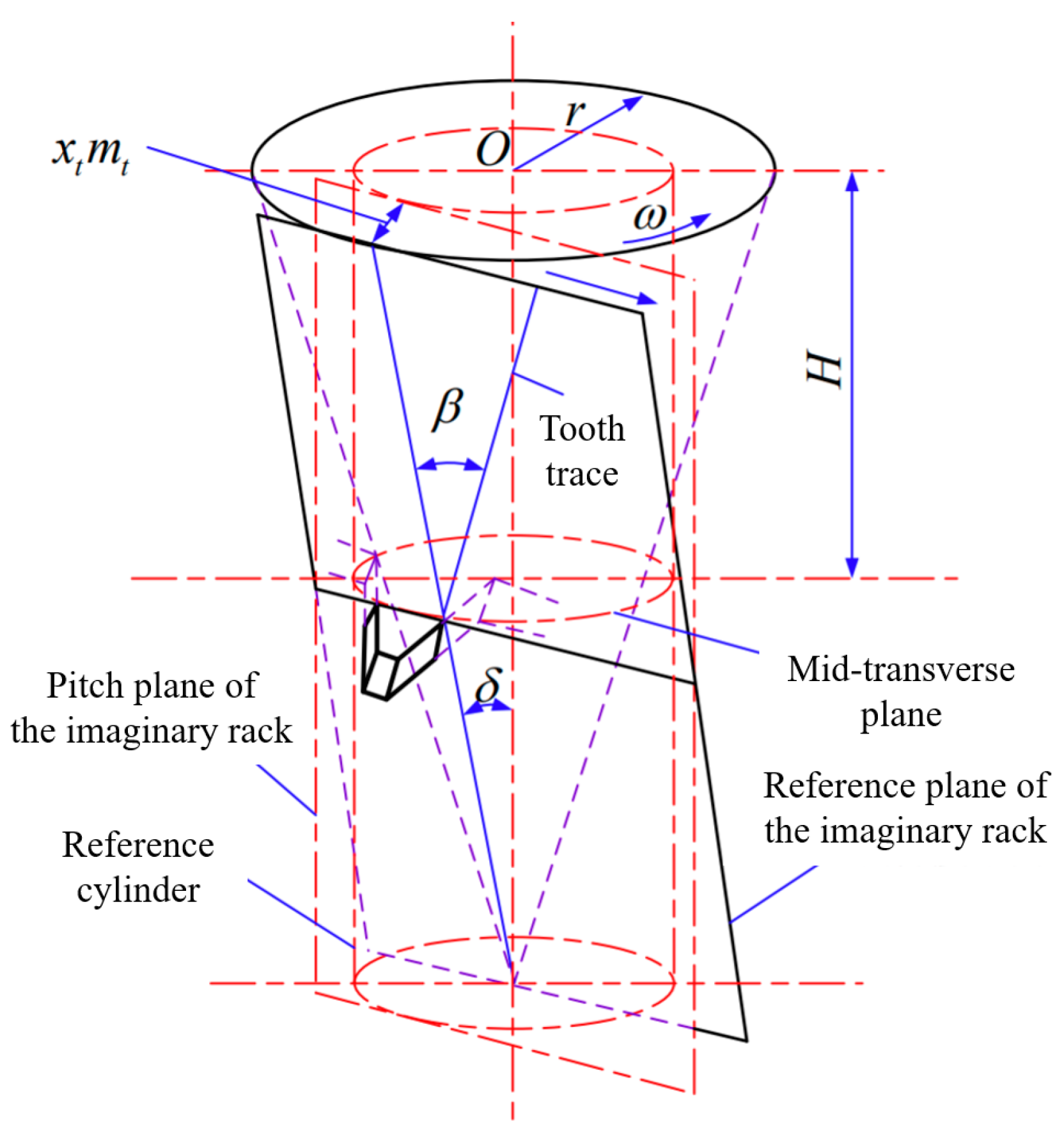
In the hobbing process of involute cylindrical gears, the hobbing cutter is fed along the gear axial direction. When a pass cutting is completed, the main motion of the gear hobbing machine includes the rotary motion of the cutter around its axis to form the cutting motion of the cutting edge, the rotary motion of the workpiece around its axis, and the feed motion of the cutter along the gear axis, the two form a generating motion. In the hobbing processing of involute helical cylindrical gears, in addition to meeting the above motion requirements, it is also necessary to meet the differential relationship between the feed motion of the cutter along the axial direction and the rotary motion of the workpiece. Compared to helical cylindrical gears, in the hobbing process of helical beveloid gears, there is a taper angle () between the imaginary rack pitch plane and the gear axis, which is shown in Figure 1:

Figure 1.
The schematic diagram of the helical beveloid gear’s structure. H—the distance between the outer transverse plane and the mid-transverse plane; —the spiral angle; —the taper angle; —addendum modification of the transverse plane; —transverse modification coefficient; —transverse module.
Therefore, in the hobbing process of helical beveloid gears, in addition to meeting the motion requirements of traditional gear processing, it is necessary to add the feed movement of the gear hobbing cutter along the gear radial. At the same time, the relationship between the axial feed rate of the gear hobbing cutter and the radial feed rate along the gear should also be considered to complete the setting of the motion parameters. Taking the right-handed involute beveloid gear as the main research object, in the hobbing process, the relative motion and the relative position between the cutter and the gear are shown in Figure 2.
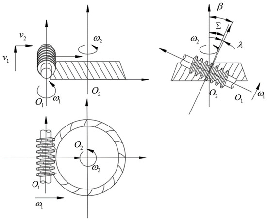
Figure 2.
The relative motion and the relative position between the cutter and the gear. —the installation angle of the cutter; —the lead angle of the cutter.
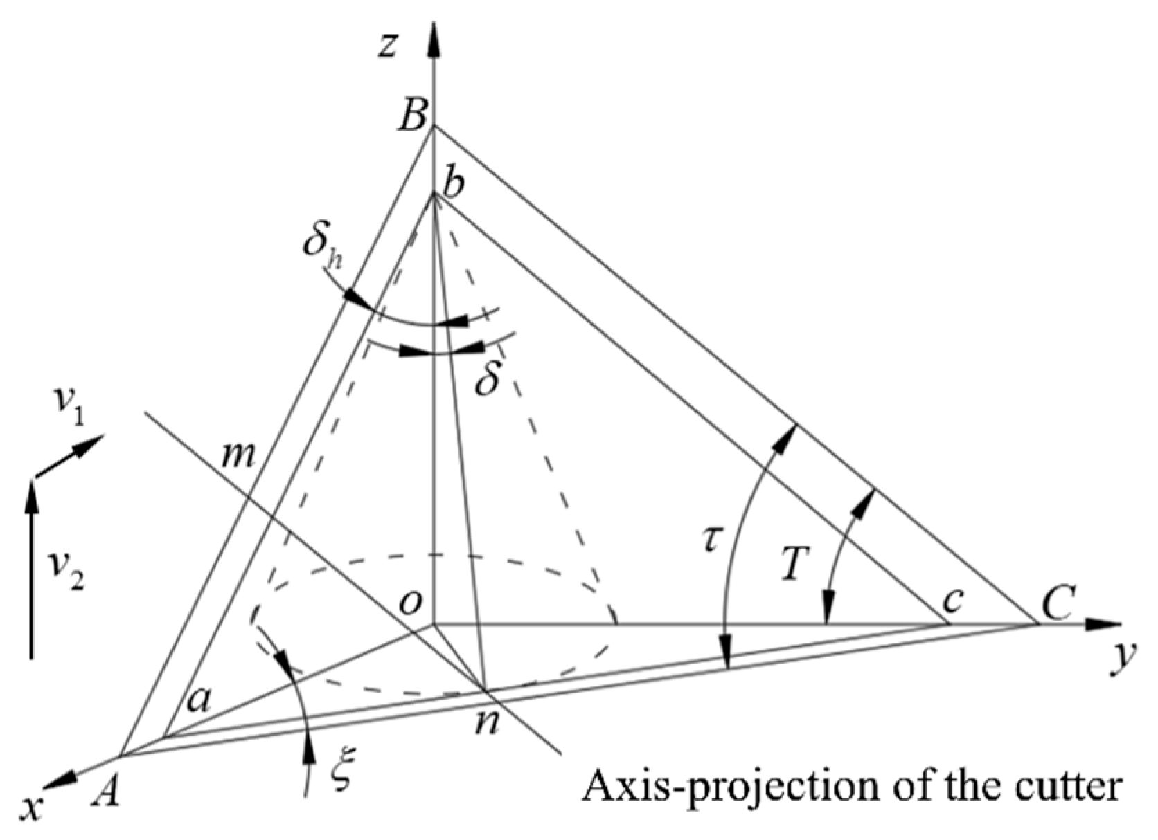
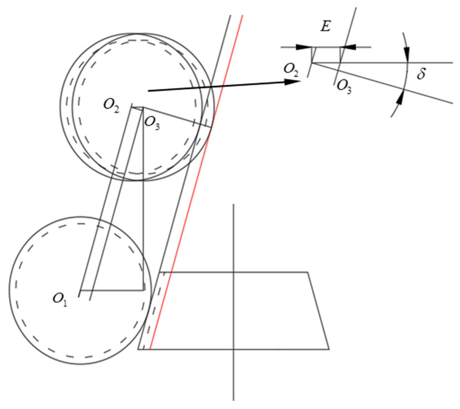
According to Figure 2, the main motion of the cutter includes the rotary motion around the axis with the angular velocity , the vertical feed motion along the gear axis direction with the velocity , the parallel feed motion along the radial direction of the gear with the velocity . The gear blank makes the rotary motion around its axis with the angular velocity . The feed rate and of the cutter are determined according to the taper angle of the beveloid gear () that is designed. The installation angle of the cutter () is determined according to the spiral angle of the beveloid gear (), the taper angle of the beveloid gear (), and the lead angle of the cutter (). The rotation speed of the gear blank is determined according to the rotation speed of the cutter, the spiral angle of the beveloid gear (), and the transmission ratio of the cutter and the gear. The schematic diagram of the relative position between the axis of the cutter and the gear blank is shown in Figure 3.

Figure 3.
The relative position between the axis of the cutter and the gear blank. —the inclination angle of the cutter axis in the plane ABC; —the motion taper angle of the cutter.
From Figure 3, the motion of the cutter axis mn produces the envelope plane ABC. The plane abc is the nominal cylindrical envelope plane of the cutter; it is also the reference plane of the counterpart rack. The plane abc is parallel to the plane ABC, and the angle between the plane abc and the z-axis is , which is the taper angle of the beveloid gear. According to the definition of the spiral angle of the beveloid gear, the inclination angle of the cutter axis () can be calculated by Equations (1) and (2).
The angle between line BC and the y-axis is the installation angle of the cutter (). Based on the spatial geometric relationship, can be calculated by Equations (3) and (4).
The motion taper angle of the cutter () is inconsistent with the taper angle of the beveloid gear (). can be calculated based on the spatial geometric relationship, so that the relationship between the axial feed motion and the radial feed motion of the cutter can be determined. The derivation process of is shown in Equations (5)–(7).
In the process of hobbing the beveloid gear, the differential motion between the gear blank and the hob forms the spiral angle. The relative motion between the cutter axis and the gear blank in the differential motion is shown in Figure 4.
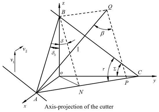
Figure 4.
The relative motion between the cutter axis and the gear blank in the differential motion.
To form the spiral angle of the beveloid gear, in other words, the envelope plane of the cutter tooth that is parallel to the tooth trace (I) of the counterpart rack, the cutter needs to translate by tangentially along the gear blank when point A on the axis of the cutter moves to point B with the movement of the cutter, so that point A moves to point Q, which converts the relative motion into the differential rotary motion between the cutter and the gear blank. The spiral angle of the differential motion of the beveloid gear in hobbing is defined as , and the derivation process of is shown in Equations (8)–(10).
2.2. Calculation of Hobbing Processing Parameters for Beveloid Gears
The dividing tooth motion and differential motion of ordinary hobbing machines are realized by the hanging wheel. The hanging wheel belongs to the external transmission chain of the hobbing machine, and different hobbing machines have different internal transmission chains in general. To realize the calculated transmission ratio, it is necessary to combine the transmission ratio of both the internal and the external transmission chain.
Hobbing the beveloid gear, the calculation method of the transmission ratio of the hobbing machine’s dividing tooth motion of the hanging wheel is the same as that of the cylindrical gear. However, the transmission ratio of the differential hanging wheel is different from that of the cylindrical gear. The transmission ratio of the hobbing machine’s dividing tooth motion can be calculated by Equation (11).
- —number of starts of the cutter;
- —dividing constant of the hobbing machine;
- —number of teeth of gear to be machined.
The differential motion transmission ratio can be calculated by Equation (12).
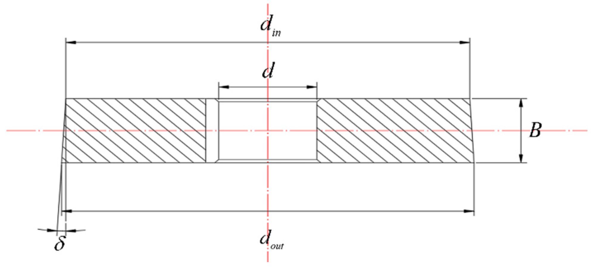
When hobbing the gear blank, the shaft hole of the gear blank is selected as the clamping positioning datum, and the outer circle of the gear blank is selected as the cutter setting datum. It is necessary to calculate the size of the gear blank before the hobbing process. The structure of the gear blank is shown in Figure 5.
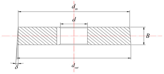
Figure 5.
The structure of the gear blank.
The thickness () and taper angle () of the gear blank are consistent with those of the gear, and the diameter of the shaft hole () is determined according to the shaft diameter. The diameter of the outer transverse plane of the gear blank can be calculated by Equation (13).
The diameter of the inner transverse plane of the gear blank can be calculated by Equation (14).
In the hobbing process of cylindrical gears, the cylinder of the gear blank is selected as the cutter aligning datum. After the cutter is aligned, the cutter is moved to the top of the gear blank along the axial direction. Rotating the radial feed handwheel of the gear hobbing machine, the cutter moved for the whole depth of the gear () along the radial direction of the gear blank.
The whole depth of the gear () can be calculated by Equation (15).
The cutter aligning datum of the beveloid gears’ hobbing process is similar to that of cylindrical gears. Selecting the round table surface of the gear blank as the cutter setting datum, and the schematic diagram of the cutter setting is shown in Figure 6. represent the axes of the cutter, and the motion path of the cutter is .
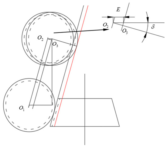
Figure 6.
The schematic diagram of the cutter setting.
—the moving distance of the cutter after the cutter aligns. It can be calculated by Equation (16).
In the hobbing process of beveloid gears, the axial feed of the cutter is expressed by the axial feed distance of the cutter holder during one rotation of the worktable. The radial movement of the cutter holder can be realized by the rotation of the handwheel, and the radial feed distance of the cutter holder during one rotation of the handwheel is defined as . The axial movement of the cutter holder can also be realized by the rotation of the handwheel, and the axial feed distance of the cutter holder during one rotation of the handwheel is defined as . To form the taper angle of the beveloid gear, the transmission ratio between the axial feed handwheel and the radial feed handwheel of the hobbing machine () needs to satisfy Equation (17).
The processing parameters and calculation formulas are summarized in Table 1. In addition, the gear rotation direction can be changed by increasing or decreasing differential hanging wheels.

Table 1.
The processing parameters and calculation formulas.
3. Modification of Hobbing Machine
3.1. Analysis of the Transmission Principle of Hobbing Machine
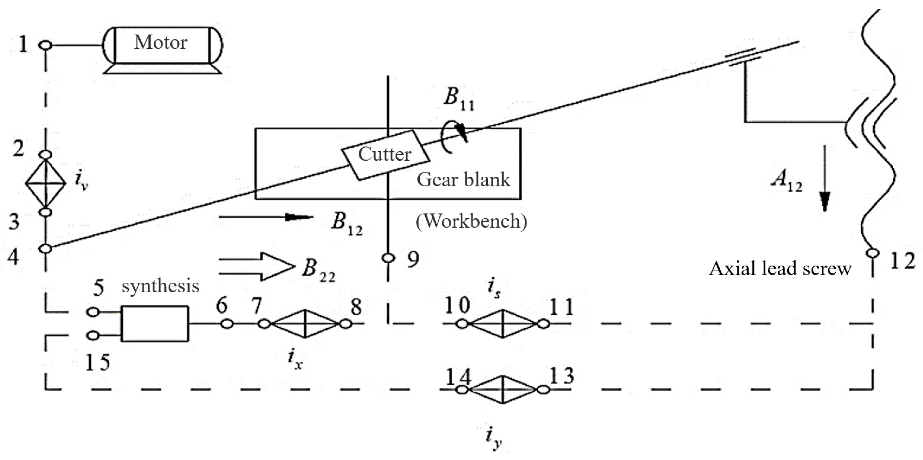
In the hobbing process of helical cylindrical gears, the diagram of the transmission principle is shown in Figure 7.
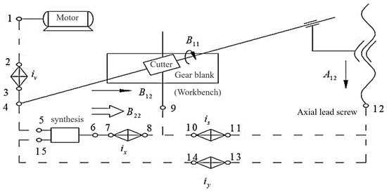
Figure 7.
The transmission principle of helical cylindrical gears hobbing process.
As is shown in Figure 7. The transmission chain includes the main motion chain, the dividing tooth motion chain, the axial feed motion chain, and the differential motion chain. In the main motion chain, the power is transmitted to the cutter from the motor so that the rotary hobbing motion of the cutter is realized. The power transmission path is . The speed of the cutter can be adjusted by the transmission ratio . In the dividing tooth motion chain, the power is transmitted to the workbench from the cutter so that the rotary dividing tooth motion of the workbench is realized. The power transmission path is . The number of gear teeth can be adjusted by the transmission ratio . In the axial feed motion chain, the power is transmitted to the axial lead screw from the workbench. The axial feed motion in the hobbing process is realized so that the complete tooth surface of the gear is processed. The power transmission path is . The speed of the axial feed motion can be adjusted by the transmission ratio . In the differential motion chain, the power is transmitted to the workbench from the cutter holder screw. Based on the dividing tooth motion, The workbench compensates for the differential motion relative to the cutter, and the spiral angle of the helical cylindrical gear is formed. The power transmission path is . The spiral angle of the gear can be adjusted by the transmission ratio .
In the hobbing process of helical beveloid gears, in addition to the axial feed motion relative to the gear blank, the cutter also needs to have a radial feed motion relative to the gear blank to form a taper angle . The relationship between the radial feed and the axial feed of the cutter relative to the gear blank should be satisfied by Equation (18).
- —the radial feed of the cutter during one rotation of the worktable (mm);
- —the axial feed of the cutter during one rotation of the worktable (mm).
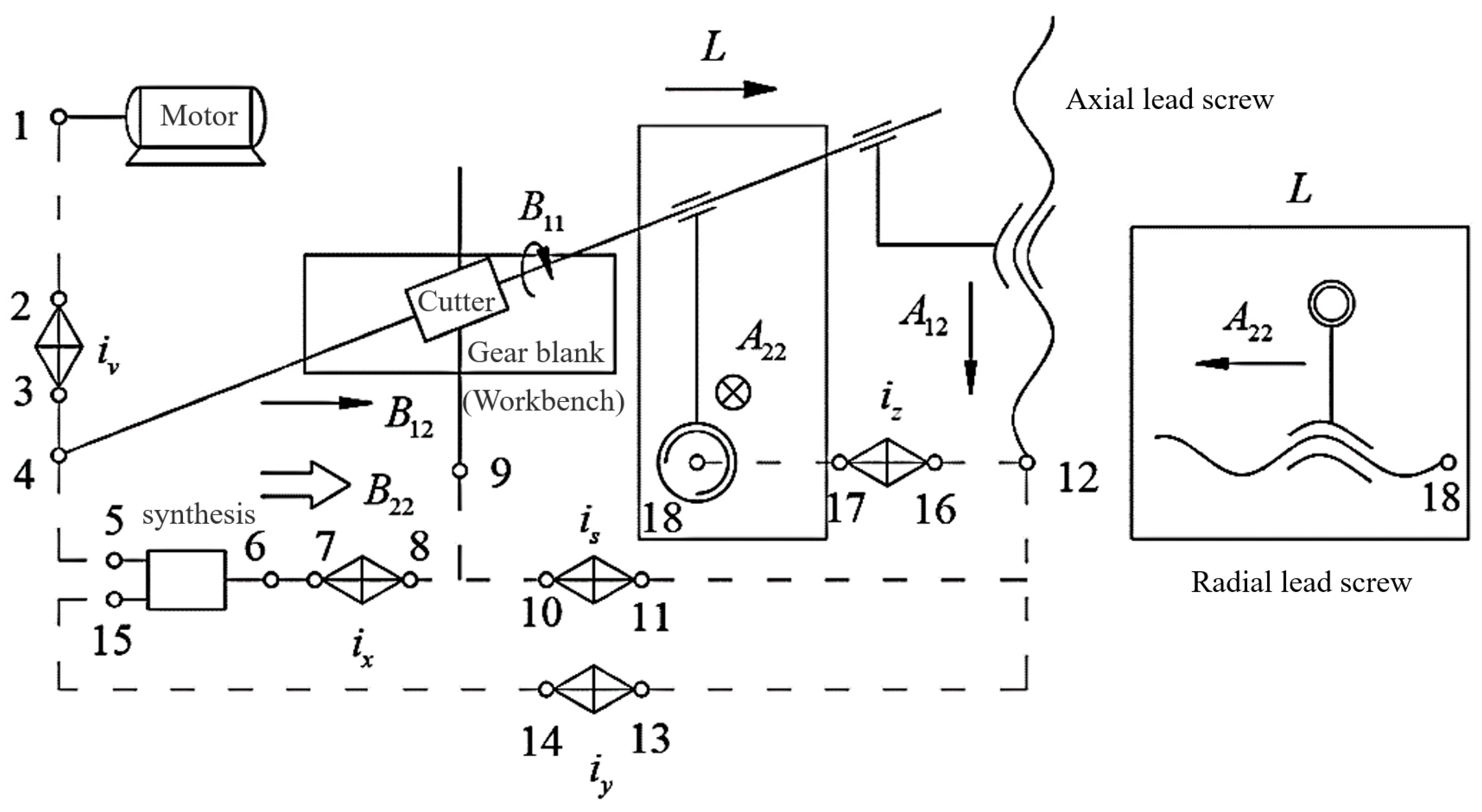
To establish the connection between the radial feed and the axial feed of the cutter of the hobbing machine, it is necessary to establish the transmission chain between the axial feed screw and the radial feed screw of the hobbing machine. To achieve these above, the taper angle transmission chain is added to the transmission chain of helical cylindrical gears. And the transmission principle of the helical beveloid gears hobbing process is shown in Figure 8.

Figure 8.
The transmission principle of helical beveloid gears hobbing process.
The power transmission path of the taper angle () transmission chain is . The taper angle () can be adjusted by the transmission ratio , which can be calculated by Equation (19).
- —the radial feed of the cutter during one rotation of the radial feed handwheel (mm);
- —the axial feed of the cutter during one rotation of the axial feed handwheel (mm).
3.2. Modification Design and Assembly of the Hobbing Machine
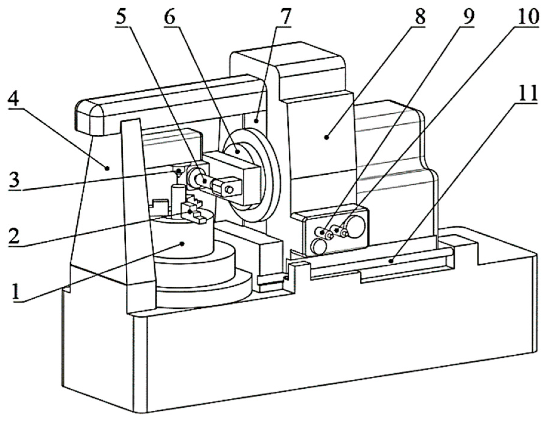
Realizing the linkage between the axial feed and the radial feed of the cutter is the purpose of modifying the hobbing machine. In our study, the Y-38 gear hobbing machine was selected for modification, and the structure schematic diagram of the Y-38 gear hobbing machine is shown in Figure 9.
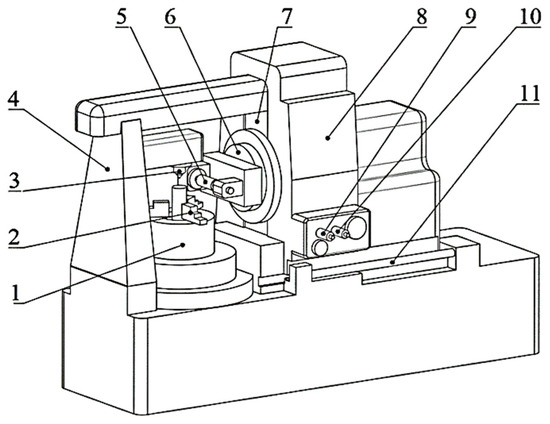
Figure 9.
The structure schematic diagram of the Y-38 gear hobbing machine: 1—rotary workbench; 2—loading fixture of the gear blank; 3—live center; 4—hobbing machine body; 5—cutter; 6—cutter holder and its turntable; 7—radial rail; 8—axial workbench; 9—axial feed handwheel shaft; 10—radial feed handwheel shaft 1-axial rail.
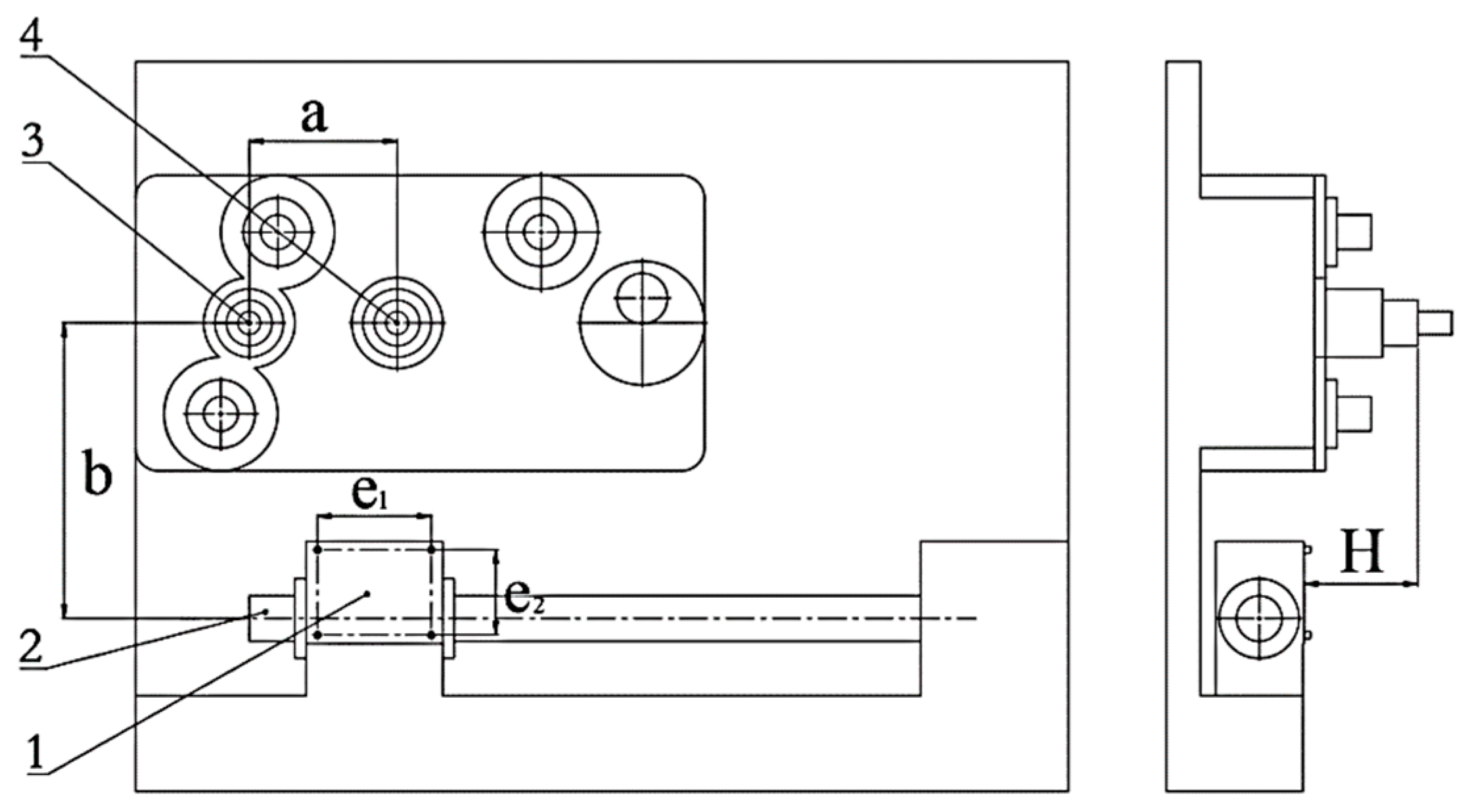
It is necessary to measure the structural dimensions of the hobbing machine accurately and determine the feed motion parameters before installing the hanging wheel mechanism. The schematic diagram of the installation position of the hanging wheel mechanism relative to the hobbing machine is shown in Figure 10.

Figure 10.
The schematic diagram of the installation position of the hanging wheel mechanism: 1—cover plate; 2—axial lead screw rail; 3—axial feed handwheel shaft; 4—radial feed handwheel shaft; a—the distance between the two handwheel shafts; b—the height difference between the center of the cover plate and the axial feed handwheel shaft axis; e1 and e2—the distance between the fixed bolt of the cover plate; H—the height difference between the cover plate transverse plane and the handwheel install plane.
After measurement, it can be obtained that a = 130 mm, b = 260 mm, e1 = 100 mm, e2 = 75 mm, H = 100 mm, the size of the cover plate is 90 mm × 120 mm, and four fixed bolts with the specification of M6 are used to fix the cover plate.
The radial and axial feed parameters of the hobbing machine were measured using a dial gauge, which was installed on the radial rail and the axial rail, respectively. After calculation, the radial feed handwheel rotates for one rotation, (on average). The axial feed handwheel rotates for one rotation, (on average).
There is a gap between the radial feed lead screw and the axial feed lead screw of the hobbing machine; although the rotating error of the axial feed motion can be eliminated by the gravity of the cutter holder, the gap of the radial feed lead screw still has an impact on the hobbing beveloid gears. After measurement, the rotating error of the radial feed motion is 0.25 mm, which needs to be eliminated during the hobbing process.
According to the axial feed motion parameters and radial feed motion parameters of the hobbing machine, the transmission ratio () between the axial feed handwheel and the radial feed handwheel was preliminarily calculated. Different taper angles of beveloid gears were selected, and the transmission ratio () was calculated as shown in Table 2.
Table 2.
The transmission ratio of the handwheel for different taper angles of beveloid gears.
To facilitate the experimental design and description, the taper angle of the beveloid gear for trial hobbing was selected as .
Due to the RPM ratio between the radial handwheel and the axial handwheel of the hobbing machine being relatively large and the center distance between the two handwheel shafts being close, it is difficult for the primary transmission to achieve a large transmission ratio. At the same time, the double-geared transmission needs to change the body of the hobbing machine greatly. For these above, the two-stage synchronous belt transmission was selected. Due to the limited space, it is inconvenient to arrange the tensioning device for the synchronous belts. In addition, due to the small torque transmitted by the hanging wheel mechanism and the slow transmission speed, the design can meet the processing requirements. The diagram of hanging wheel transmission in synchronous belt type is shown in Figure 11.
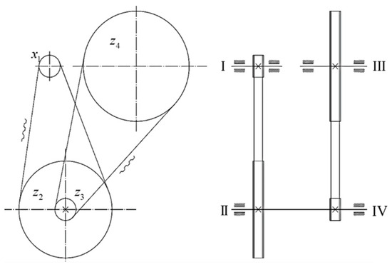
Figure 11.
The diagram of hanging wheel transmission with synchronous belt type.
According to Equation (17), can be calculated as follows:
To facilitate the selection of the synchronous belt, the structure of the hanging wheel should be compacted, and the center distance of the synchronous belt should be closed. The transmission ratio was assigned as , . According to the install position and the diameter of the install shaft, the number of axial synchronous belt wheel teeth was determined as , the number of radial synchronous belt wheel teeth was determined as , the number of the large center synchronous belt wheel teeth was determined as , the number of the small center synchronous belt wheel teeth was determined as .
The actual transmission ratio of the synchronous belt hanging wheel was calculated by Equation (20).
The actual taper angle was calculated by Equation (21).
The deviation between the actual taper angle and the design taper angle was calculated by Equation (22).
From Equation (22), the deviation was within the allowable range and met the processing standard. If the design taper angle is another angle, it can be achieved by changing the number of the large center synchronous belt wheel teeth ().
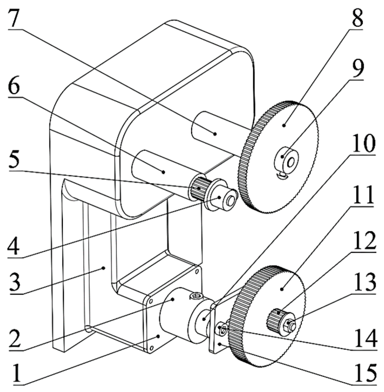
According to the model and the teeth number of the synchronous belt wheel selected, the three-dimensional assembly drawing of the hanging wheel mechanism is shown in Figure 12.

Figure 12.
The three-dimensional assembly drawing of the hanging wheel mechanism: 1—cover plate; 2—shaft seat; 3—hobbing machine body; 4—fix bolt of axial synchronous belt wheel; 5—axial synchronous belt wheel; 6—axial rotary shaft 7—radial rotary shaft; 8—radial synchronous belt wheel; 9—fix bolt of radial synchronous belt wheel; 10—center rotary shaft; 11—large center synchronous belt wheel; 12—small center synchronous belt wheel; 13—fix bolt of the hanging wheel; 14—connecting plate screws; 15—connecting plate.
The center distance of the synchronous belt wheels was measured, and the synchronous belt model was selected as M5-830. In addition, the tensioning of the synchronous belt can be realized by adjusting the connecting plate. As shown in Figure 12, there is a guide groove on the connecting plate, and the spatial relative position of the center synchronous belt wheel can be adjusted by loosening the connecting plate screws so that the preload of the synchronous belt can be adjusted.
4. Hobbing Beveloid Gears
4.1. Calculation of Hobbing Parameters and Hobbing Process
The process of hobbing beveloid gears mainly includes determining the basic parameters of beveloid gears, calculating the hobbing parameters based on the parameters of beveloid gears and cutters, determining the number of hanging wheel teeth by checking the table, assembling the hanging wheels on the hobbing machine, clamping the gear blank, setting the cutter, retracting the cutter, feeding the cutter and hobbing gears.
According to the study in Section 2 and Section 3, taking the involute helical beveloid gear with specific parameters as an example, the process of hobbing the beveloid gear is introduced as follows.
The basic parameters of the beveloid gear are set as shown in Table 3.
Table 3.
The basic parameters of the beveloid gear.
The basic parameters of the cutter are set, as shown in Table 4.
Table 4.
The basic parameters of the cutter.
The calculation of the basic parameters of the gear blank are shown in Table 5.
Table 5.
The basic parameters of the gear blank.
The calculation results of the hobbing parameters are shown in Table 6.
Table 6.
The hobbing parameters.
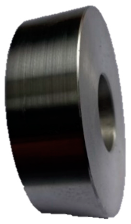
Hobbing the outer circle, transverse plane, and shaft hole of the gear blank. The gear blank hobbing was completed, as shown in Figure 13.

Figure 13.
The gear blank before gear hobbing.
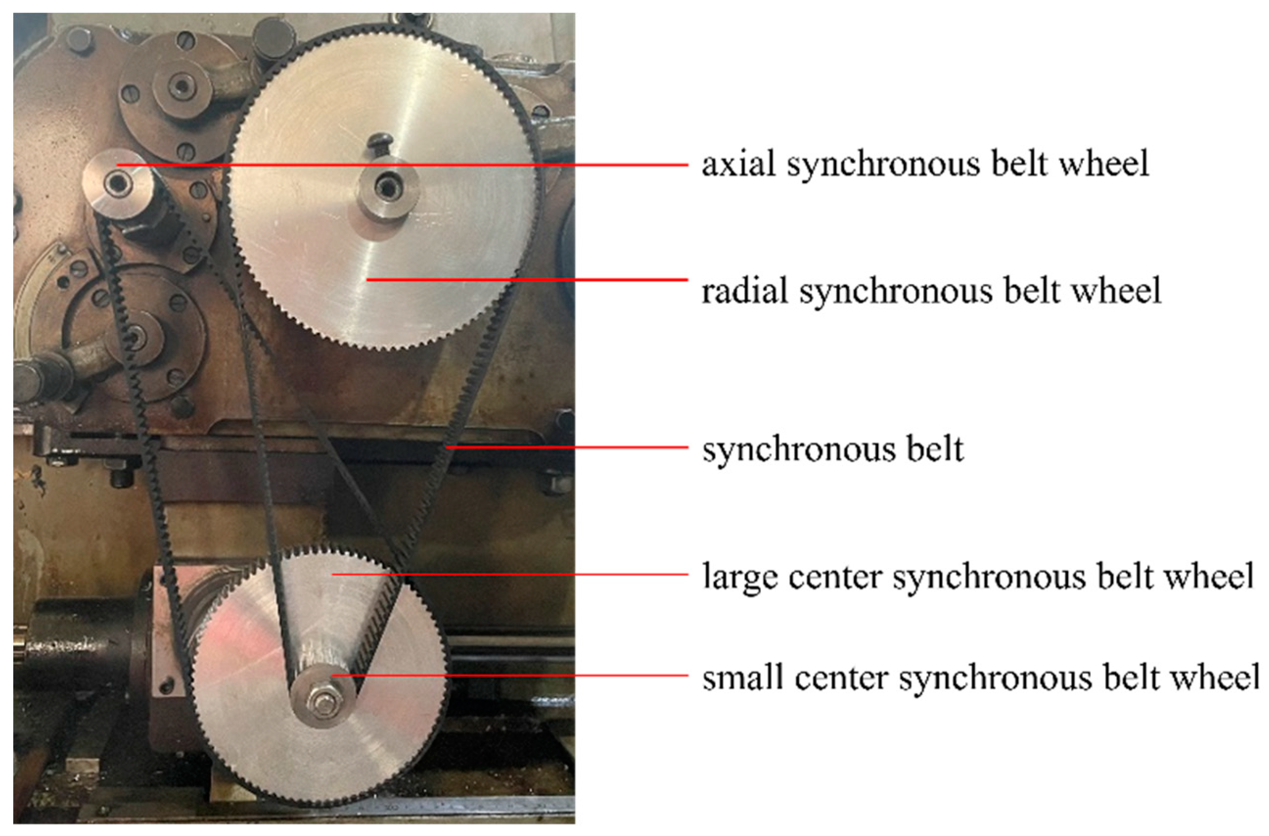
According to the calculated hanging wheel transmission ratio, assembling the dividing tooth hanging wheel and the differential hanging wheel. The machining efficiency and tooth surface processing quality should be considered before selecting and assembling the appropriate axial feed hanging wheel. The diagram of the hanging wheel mechanism assembling is shown in Figure 14.
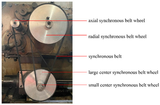
Figure 14.
The diagram of the hanging wheel mechanism assembling.
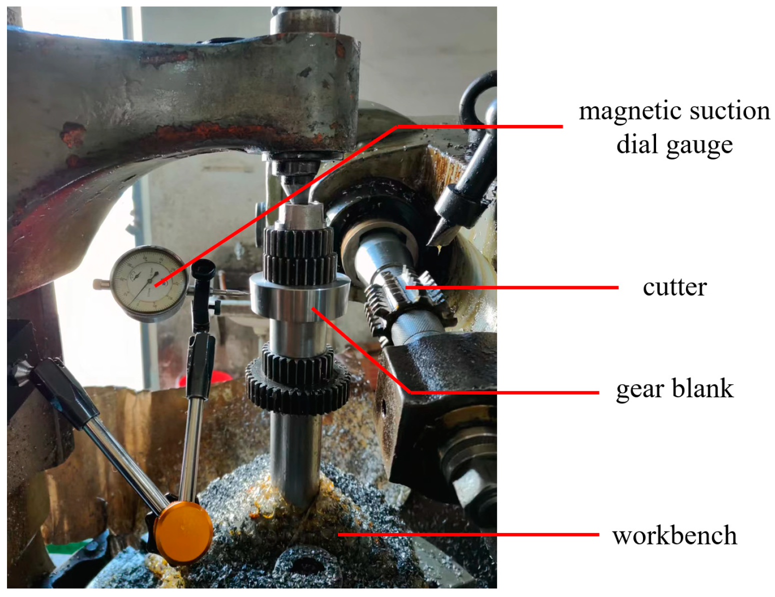
According to the lead angle of the cutter and the spiral angle of the beveloid gear to be processed, the cutter installation angle was determined, and the cutter was assembled. We clamped the gear blank on the loading fixture. Then, we measured the radial runout of the gear blank and fine-tuned the gear blank until the hand of the dial gauge was stable. The gear blank after clamping is shown in Figure 15.

Figure 15.
The diagram of the gear blank after clamping.
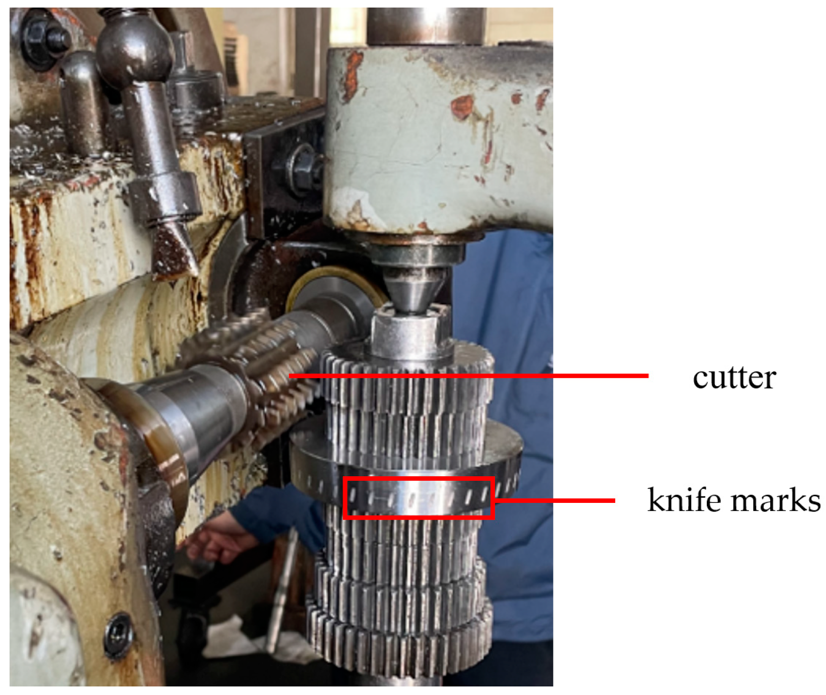
Take the side of the gear blank as the reference, rotating the radial feed handwheel slowly until the tip of the cutter touches the side of the gear blank, as shown in Figure 16.

Figure 16.
The diagram of the gear blank after the cutter aligning.
It is necessary to rotate the radial feed handwheel to keep the hob away from the gear blank if the knife marks are too deep. Then, rotating the radial feed handwheel in reverse to make the cutter close to the gear blank so that the handwheel rotation error can be eliminated. After the cutter aligned, we installed the synchronous belt of the hanging wheel, raised the cutter to the top of the gear blank, and then removed the synchronous belt. Next, we rotated the radial feed handwheel to make the cutter move to the axis of the workbench. During the cutter alignment process, it is necessary to consider the radial feed lead screw gap so that the rotation error can be eliminated. Aligning the cutter and installing the synchronous belt of the hanging wheel again, starting the machine, and the hobbing process of the beveloid gear was completed.
4.2. Error Measurement and Analysis
The accuracy grade of the gear has a significant impact on the transmission efficiency. Improving the accuracy grade of the gear, the load distribution of the gear is more uniform, the accuracy and stability of the transmission motion are better, the energy loss caused by the vibration and impact of the gear is reduced, and the transmission efficiency is improved. In the industry standard, the 6-level accuracy has requirements for the size, tooth pitch error, tooth profile deviation, etc. According to the actual situation of our experiment, only some of the parameters are calculated and compared, and the corresponding industry standards are also listed in the paper. Error detection was performed on the machined beveloid gear. The test items include the distance from the root circle of the outer transverse plane to the top diameter of the shaft hole (), the distance from the root circle of the inner transverse plane to the top diameter of the shaft hole (), the chordal thickness of the reference circle (), the total deviation of the left tooth surface reference circle helix () and the total deviation of the right tooth surface reference circle helix (). The schematic diagram of the measurement is shown in Figure 17.
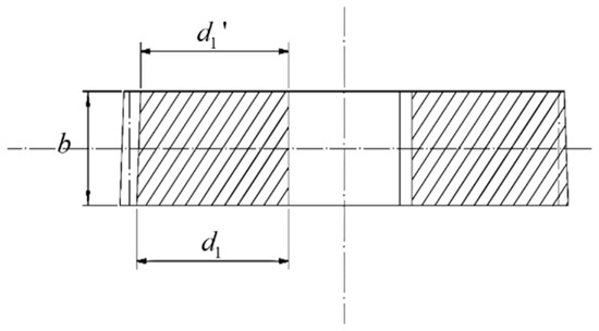
Figure 17.
The schematic diagram of the measurement.
The machined taper angle () can be calculated indirectly by the result of measuring the distance from the root circle of the outer transverse plane to the top diameter of the shaft hole (), the distance from the root circle of the inner transverse plane to the top diameter of the shaft hole () and teeth width (). The machined taper angle () can be calculated by Equation (23).
The taper angle deviation () can be calculated by Equation (24).
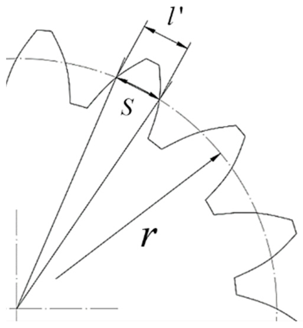
Due to the different radii of the base circle of the beveloid gear’s left and right tooth surfaces, the tooth thickness error cannot be detected by measuring the common normal. Instead, we measured the chordal thickness of the reference circle () and that in theoretical () to analyze the error. The relationship between the chordal thickness of the reference circle () and the tooth thickness of the reference circle is shown in Figure 18.

Figure 18.
The diagram of the relationship between the chordal thickness and the tooth thickness of the reference circle.
On the outer transverse plane of the beveloid gear, the tooth thickness of the reference circle () can be calculated by Equation (25). and the circular thickness on the diametral pitch (DP) of the reference circle in theoretical () can be calculated by Equation (26).
The reference circle helix of the beveloid gear was selected as the measurement object. To analyze the total deviation of the helix of the beveloid gear, it is necessary to calculate the reference circular spiral angle of the beveloid gear separately. The spiral angle of the left tooth surface of the beveloid gear () can be calculated by Equation (27), and the spiral angle of the right tooth surface of the beveloid gear () can be calculated by Equation (28).
According to the size of the spiral angle, the ratio of the differential hanging wheel of the hobbing machine was calculated. After selecting the appropriate hanging wheel and assembling the mechanism, we adjusted the clutch of the hobbing machine so that the axial motion of the cutter holder and the rotary motion of the workbench could be realized. In addition, to measure the deviation of the helix of the beveloid gear, the magnetic suction gauge was placed on the cutter holder of the hobbing machine and moved with the tool holder. At the same time, the contact head of the magnetic suction gauge was in contact with the reference circle of the tooth surface to be measured. The measurement results of the beveloid gear size of the hobbing processing are shown in Table 7.
Table 7.
The measurement results of the beveloid gear size.
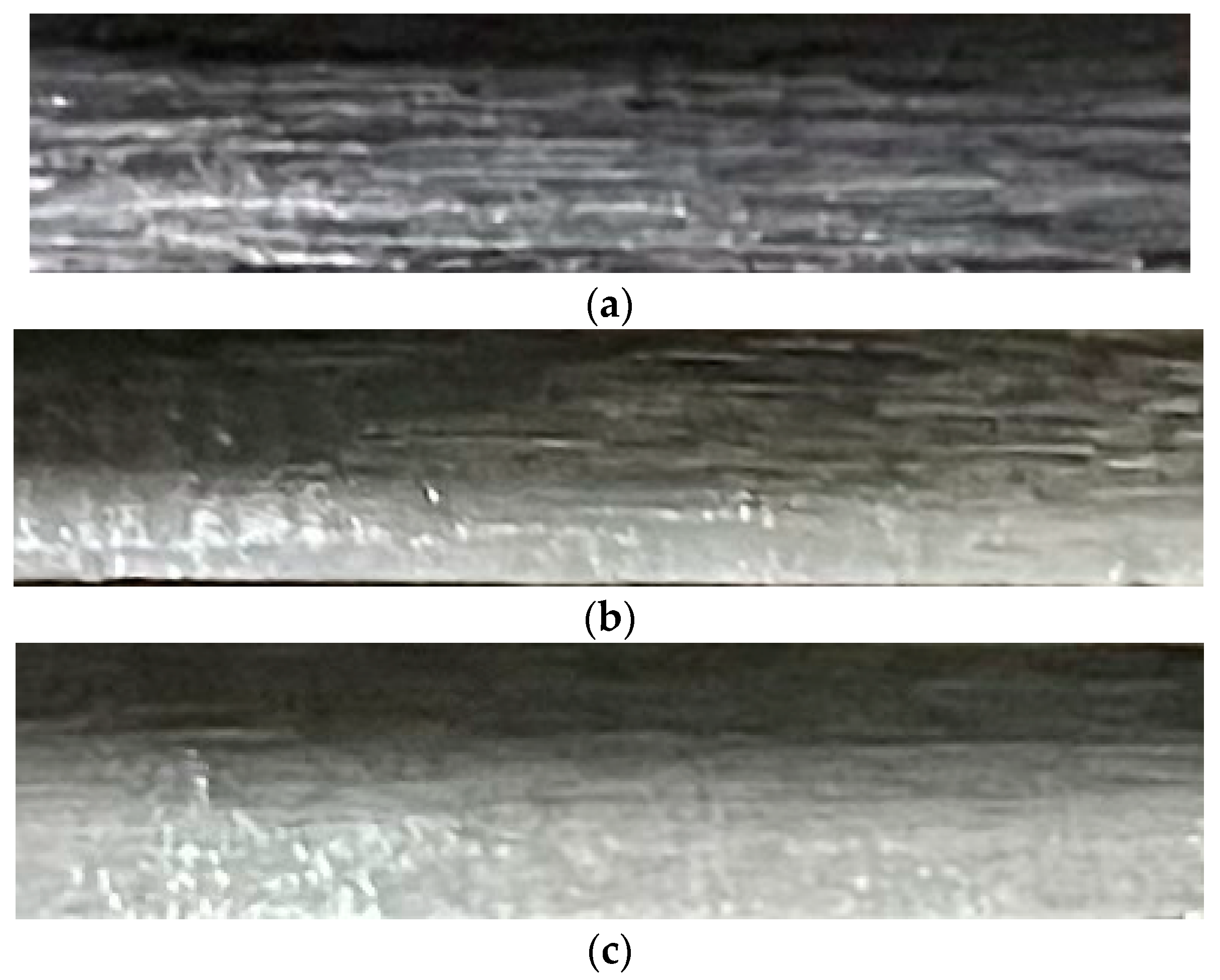
Due to the structural limitation of the hobbing machine, the synchronous belt tensioning device was not installed, which led to the radial feed handwheel rotating in a crawling state and reducing the machining quality of the gear tooth surface. After reducing the axial feed, although the crawling state of the radial feed handwheel cannot be eliminated, the machining quality of the tooth surface was significantly improved. For the above, we not only reduced the axial feed but also hobbed the gear twice so that the crawling state of the radial feed handwheel was eliminated and the quality of tooth surface machining was improved.
When the axial feed was selected as 1 mm/r, the state of the tooth surface for single hobbing is shown in Figure 19a.

Figure 19.
(a) The state of the tooth surface for single hobbing with the axial feed of 1 mm/r. (b) The state of the tooth surface for single hobbing with the axial feed of 0.5 mm/r. (c) The state of the tooth surface for double hobbing with the axial feed of 0.5 mm/r.
When the axial feed was selected as 0.5 mm/r, the state of the tooth surface for single hobbing is shown in Figure 19b.
When the axial feed was selected as 0.5 mm/r, the state of the tooth surface for double hobbing is shown in Figure 19c.
Based on the 6-level accuracy standard of GB/T11334-2005 “Geometrical Product Specifications (GPS) Taper Tolerance” [44], the taper tolerance of the beveloid gear was selected as 0.02° according to the table. The deviation between the actual value of the beveloid gear taper angle and the theoretical value was calculated as Equation (29).
From the result of Equation (29), it can be found that the taper deviation of the beveloid gear was within the tolerance range and met the 6-level accuracy standard. The deviation of the taper angle of the beveloid gear is mainly caused by the gap of the feed screw of the hobbing machine, the teeth number rounding of the synchronous belt wheel in the synchronous belt hanging wheel, and the transmission error of the internal transmission chain of the hobbing machine. To improve the accuracy of the taper angle of the beveloid gear, an improvement scheme can be proposed from the above aspects.
According to GB/T10095.1-2022 [45] “Cylindrical gears—ISO system of flank tolerance classification—Part 1: Definitions and allowable values of deviations relevant to flanks of gear teeth” [45] and referring to the 6-level accuracy grade standard for cylindrical gears, the tolerance of the circular thickness on the DP of the reference circle was obtained as 0.005 mm by checking the table. And the total deviation of the helix of the beveloid gear was obtained as 0.011 mm. It is calculated that the theoretical chordal thickness of the reference circle of the outer transverse plane of the beveloid gear () is 3.667 mm. The deviation of the chordal thickness was calculated by Equation (30).
From Equation (30), the result meets the 6-level accuracy standard within the allowable tolerance range. The chordal thickness error of the beveloid gear reference circle is mainly caused by the size error of the cutter and the transmission error of the hanging wheel of the hobbing machine. The accuracy of the chordal thickness of the beveloid gear can be improved from these two aspects.
Finally, we measured the total deviation of the left and right tooth surface reference circle helix () of the beveloid gear. The results showed that the hand of the dial gauge swung around the 0 lines, and the maximum runout did not exceed 0.01 mm. According to these above, the beveloid gears hobbed met the 6-level accuracy standard.
5. Conclusions
To improve the machining efficiency and accuracy of processing beveloid gears, reduce processing costs, and promote the mass production and industrial application of beveloid gears, we proposed a beveloid gear hobbing processing method based on the modification of ordinary gear hobbing machine and verified the feasibility and accuracy of the method via actual processing.
Firstly, according to the structural characteristics of beveloid gears, we analyzed the relative position and relative motion relationship between the cutter and the gear blank during the hobbing process based on the principle and method of gear hobbing. And the calculation method of the relevant processing parameters such as feed, cutter installation angle, and feed distance of the beveloid gears was derived.
Next, we designed the transmission chain between the axial feed and the radial feed of the hobbing machine and analyzed the transmission relationship between them by combining the transmission principle of helical cylindrical gears in the gear hobbing machine and the hobbing requirements of beveloid gears. After that, we analyzed the structural dimensions and feed motion parameters of the hobbing machine and then designed the modification scheme of the gear hobbing machine. We realized the linkage between the axial feed and the radial feed of the hobbing machine via the designed hanging wheel mechanism in synchronous belt type so that the hobbing processing requirements of beveloid gears were satisfied.
Finally, we completed the actual hobbing processing of the beveloid gear and verified the feasibility of the method proposed before. Then, the error measurement and analysis of the trial-produced beveloid gear were carried out. The results showed that the accuracy of the trial-produced beveloid gear met the 6-level standard, which meets the accuracy requirements of machining, and the accuracy of the processing method proposed in this study was verified.
Author Contributions
J.W. conceived and designed the study and applied for the funding which financially supported the study. H.Y. conducted data extraction, performed the analyses, and wrote the article. B.Y. and H.L. provided their comments and suggestions during discussions and by writing, especially on the data extraction method and paper formatting. All authors have read and agreed to the published version of the manuscript.
Funding
This research was funded by the National Natural Science Foundation of China under Grant Nos. 52075116 and 52175082 and the Natural Science Foundation of Shandong Province under Grant No. ZR2021ME025.
Data Availability Statement
Data are not available due to restrictions privacy or ethical, confidentiality.
Conflicts of Interest
The authors declare no conflicts of interest.
References
- Yu, D. Research on the evaluation index system of comparative advantage of waterway transportation. Transp. Res. 2018, 4, 1–6. [Google Scholar] [CrossRef]
- Dong, S.; Wo, M. Advantages of large-scale equipment for waterway transportation. Water Transp. Sci. Technol. Inf. 1998, 4, 8–9. [Google Scholar]
- Fu, X. Opportunities and Challenges Faced by Waterway Transport in the New Era. Pearl River Water Transp. 2023, 11, 21–23. [Google Scholar] [CrossRef]
- Han, J. Exploring the economic development advantages of low-carbon economy sewer transportation. China Storage Transp. 2023, 10, 104–105. [Google Scholar] [CrossRef]
- Liu, J.; Chen, R.; Li, S.; Hu, X. Development and Application of Intelligent Waterway Transportation System: Case Study and Prospect. Traffic Inf. Secur. 2023, 41, 175–181. [Google Scholar]
- Li, M. Water transport under the new economic situation. China Shipp. Wkly. 2021, 12, 46–47. [Google Scholar]
- Wang, Y. Analysis of ship development trend. Heilongjiang Sci. 2016, 7, 108–109. [Google Scholar]
- Li, Y.; Zheng, Z.; Wu, T.; Dou, Z. Development Trend and Challenges of Intelligent Ships in the Era of Industry 4.0. Ship Eng. 2023, 45 (Suppl. S1), 224–229. [Google Scholar] [CrossRef]
- Xu, W.; Qu, R.; Xue, G.; Xu, M.; Zhu, X.; Liu, Z.; Zhang, Q. Research status and development trend of intelligent ship system. Ship 2023, 34, 46–55. [Google Scholar] [CrossRef]
- Wu, Q. Research status and future development trend of intelligent ships. China Shipp. Wkly. 2023, 22, 51–53. [Google Scholar]
- Chang, S. Technology development status and the prospect of ship high-power gear transmission device. Ship Sci. Technol. 2010, 32, 17–22+45. [Google Scholar]
- Zhang, L. Development of ship gear device. Mech. Electr. Equip. 1992, 6, 26–28. [Google Scholar]
- Wang, H. Study on Contact Analysis and Dynamic Characteristics of Small Inclination Marine Gearbox. Ph.D. Thesis, Chongqing University, Chongqing, China, 2010. [Google Scholar]
- Yang, T. Study on Dynamic Characteristics of New Marine RV Transmission Gearbox. Master’s Thesis, Harbin Institute of Technology, Harbin, China, 2016. [Google Scholar]
- Zhu, C. Research and Application of Key Technologies of Spatial Variable Tooth Thickness Transmission; Chongqing University: Chongqing, China, 1 December 2013. [Google Scholar]
- Wu, J.; Li, G.; Wang, Q.; Sun, Z.; Li, H. Analysis and calculation of the differential difference of RV reducer for robot beveloid gear. Mech. Des. 2000, 3, 24–26+28–29+47. [Google Scholar] [CrossRef]
- Beam, A.S. Beveloid gearing. Mach. Des. 1954, 26, 220–238. [Google Scholar]
- Li, G.; Wu, J.; Li, H.; Qi, Y.; Lin, S.; Chen, X. Design and calculation of meshing involute thickening gears in parallel shafts. China Mech. Eng. 2000, 8, 52–55+53. [Google Scholar]
- Du, X.; Zhu, C.; Song, D.; Xu, X. Current situation and development trend of interleaved shaft helical gear transmission variable tooth thickness technology. Mech. Des. 2012, 29, 1–7. [Google Scholar] [CrossRef]
- Liu, H.; Lou, Y.; Liu, Q.; Chan, C.Y. Forming method to process drum gears. China Heavy Equip. 2008, 2, 20–24. [Google Scholar] [CrossRef]
- Wang, Y. Discussion on the technology of forming gear processing. Heavy Mach. Sci. Technol. 2002, 3, 11–14. [Google Scholar] [CrossRef]
- Wang, H. Forming Tooth Grinding. Automot. Technol. Mater. 2008, 1, 56–58. [Google Scholar]
- Zhang, H.; Lou, Z.; Zhang, X.; Gao, B.; Nan, B. Research on the application of straight bevel gear milling technology//Chinese Society of Aeronautics and Astronautics. In Proceedings of the 4th China Aviation Science and Technology Conference in 2019, Shenyang, China, 15 August 2019; China Aviation Publishing & Media Co.: Beijing, China, 2019; p. 8. [Google Scholar]
- Zhu, M. Hobbing of spur bevel gear. Shanghai Mach. 1965, 7, 15–18. [Google Scholar]
- Zhang, S. The Gear Shaping Processing Method Using Gear Shaping Machine; Xi’an Aviation Power Co., Ltd.: Xi’an, China, 1 August 2010. [Google Scholar]
- Yang, H. Research on shaving processing technology and grinding of shaving cutter. Sci. Technol. Innov. Appl. 2017, 15, 112. [Google Scholar]
- Hong, D. Honing the large gear on the vertical lathe. Mach. Manuf. 1988, 5, 8–10. [Google Scholar]
- Li, R.; Huang, L.; Chen, C. Research on design and modeling method of spiral bevel gear based on general CNC machining. Sci. Technol. Innov. 2023, 5, 23–27. [Google Scholar]
- Yao, L. Design Theory and CNC Machining Method of Concave-Convex Arc Gear. Ph.D. Thesis, South China University of Technology, Guangzhou, China, 2018. [Google Scholar]
- Wang, M. Research on CNC Machining Method of Linear Contact Arc Bevel Gear. Master’s Thesis, Tianjin University, Tianjin, China, 2022. [Google Scholar] [CrossRef]
- Shen, Y.; Sun, R. Application and processing of variable tooth beveloid involute gear. Mech. Des. Res. 2003, 3, 83–84+55-9. [Google Scholar] [CrossRef]
- Zhang, Q. CNC transformation of gear hobbing machine. J. Anhui Metall. Sci. Technol. Vocat. Coll. 2004, 2, 35–37. [Google Scholar]
- He, J.; Wu, X. Principle of involute beveloid gear hobbing. Mech. Sci. Technol. 2003, 5, 751–753. [Google Scholar]
- Huang, J. Research on the Processing Method of Spatially Beveloid Gear Pair. Master’s Thesis, Harbin Institute of Technology, Harbin, China, 2015. [Google Scholar]
- Wu, J.; Li, G.; Li, H. Research on the diagonal inserting process of internal meshing beveloid gear pair. J. Xi’an Pet. Inst. (Nat. Sci. Ed.) 2000, 3, 45–48+0. [Google Scholar]
- Hu, R. Design and Research of Precision Inserting Involute Variable Tooth Thickness Internal Gear Shaping Cutter. Master’s Thesis, Chongqing University, Chongqing, China, 2022. [Google Scholar] [CrossRef]
- Brecher, C.; Brumm, M.; Hübner, F.; Henser, J. Influence of the manufacturing method on the running behavior of beveloid gears. Prod. Eng. 2013, 7, 265–274. [Google Scholar] [CrossRef]
- Wen, J.; Li, G.; Li, X.; Zhang, X.; Liu, Y. Research on modification method of non-involute beveloid gear. J. Harbin Eng. Univ. 2003, 6, 660–663. [Google Scholar]
- Jiang, P. Research on Grinding Method of Conical Worm Grinding Wheel for Beveloid Gear. Master’s Thesis, Chongqing University, Chongqing, China, 2019. [Google Scholar]
- Zhang, Y. Research on the Grinding Processing Method of Involute Beveloid Gear. Master’s Thesis, Lanzhou University of Technology, Lanzhou, China, 2022. [Google Scholar]
- Liao, Y.; Zhu, P.; Zhao, W.; Lu, J.; Han, F. Development and application of CNC machining and system of variable tooth thick gear. Mod. Mach. 1997, 3, 20–22. [Google Scholar]
- Wang, Z.; Shen, Y.; Xu, F.; Zhou, L. Honing of beveloid gear. Mech. Des. Res. 2007, 3, 106–108. [Google Scholar] [CrossRef]
- Sun, H. Analysis of heat treatment process of 45 steel for gear. Sci. Technol. Innov. 2014, 3, 31. [Google Scholar] [CrossRef]
- GB/T 11334-2005; Geometrical Product Specifications (GPS) Taper Tolerance. Standards Press of China: Beijing, China, 2005.
- GB/T10095.1-2022; Cylindrical Gears-ISO System of Flank Tolerance Classification-Part 1: Definitions and Allowable Values of Deviations Relevant to Flanks of Gear Teeth. Standards Press of China: Beijing, China, 2022.


Disclaimer/Publisher’s Note: The statements, opinions and data contained in all publications are solely those of the individual author(s) and contributor(s) and not of MDPI and/or the editor(s). MDPI and/or the editor(s) disclaim responsibility for any injury to people or property resulting from any ideas, methods, instructions or products referred to in the content. |
© 2024 by the authors. Licensee MDPI, Basel, Switzerland. This article is an open access article distributed under the terms and conditions of the Creative Commons Attribution (CC BY) license (https://creativecommons.org/licenses/by/4.0/).