1. Introduction
Cycloidal drives assure low transmission errors and, consequently, high precision in the positioning of the controlled elements. For this reason, their usage is widely diffused in robotics and precision machines subjected to heavy loads [
1]. However, their capability to provide high reduction ratios with compact layouts and short kinematic chains is also becoming an interesting feature for power transmission tasks [
2], in which more conventional solutions are usually employed (e.g., based on involute gears). For these applications, the relevant performance is the transmission efficiency, while the transmission error becomes of secondary importance [
3].
In a recent project, we designed a cycloidal drive dedicated to machines for construction yards [
4,
5,
6]. The proposed solution is a Wolfrom-based configuration that suggests the adoption of cycloidal stages with a low number of big teeth [
7]. This feature is particularly advantageous for machines potentially affected by unpredictable overloads, often operating in off-design or in harsh environmental conditions. Since the considered application field requires a cost-effective solution, an aspect worthy of investigation is the relationship between the performance of the system and the dimensional error of the cycloid’s profile and rollers. More specifically, we are interested in comparing the sensitivity to dimensional errors of the Wolfrom configuration against the traditional Mono-stage, which is characterized by a high number of small teeth and, therefore, is expected to be more critical.
The literature is crowded with contributions that investigate the impact of dimensional errors on the transmission error of cycloidal drives. In [
8], a new type of cycloidal reducer is presented, which differs from the traditional configuration in the pin-hole mechanism used to extract the output motion. In reference to the new configuration, the authors performed an analysis aimed at verifying the impact of the proposed solution on the dynamic transmission error. The contribution presented in [
9] discusses the issue related to the torque ripple that affects the (input or output) shafts of a cycloidal drive. The analysis considers nominal dimensions and machining tolerances and shows how the latter affects the torque ripple. In [
10], the authors study the multi-tooth contact characteristics caused by modifying the cycloid profile. The investigation was performed using a new Finite Element (FE) model that was validated through a prototype. The study is focused on improving the understanding of the influence that a tooth profile modification has on the transmission accuracy and torsional stiffness of a reducer. Paper [
11] investigates the impact on transmission efficiency due to the assembly dimensional chain. The analysis is focused on deepening the relationship between power losses and cycloid–pinion interactions. A comparison via FE and dynamical multi-body analysis between a conventional cycloidal drive and its involute-tooth kinematical equivalent is presented in [
12]. The performed simulations characterized the torque ripple behavior and the contact conditions and compared the traditional involute design against the cycloidal one in reference to efficiency. Paper [
13] performed an analysis focused on the impact that production failures can potentially have on transmission fluctuations and backlash of a cycloidal drive. The author considers a shift of the cycloidal profile due to a dimensional error and determines its influence on the transmission ratio. The effects of tolerance and friction on the multi-contact and output torque of a cycloidal reducer were investigated in [
14]. The scholars found that torsional stiffness and output torque are considerably affected by tolerances, as they decrease the stiffness while increasing the output torque fluctuation. In [
15], the distribution of contact forces was determined with reference to the tolerance of the radius of the bushings’ arrangement and the holes in the planet wheel. The outcomes of the analysis show that backlash distribution, contact forces, and pressures largely depend on these parameters. The impact of radial and pin-hole tolerances and eccentricity errors on contact stress, transmission error, gear ratio, and load on bearings was investigated in [
16], in reference to the theoretical geometry of a cycloidal reducer, concluding that these parameters play a key role. The impact of a mismatch between the cycloid–pin gear pair was also investigated in [
17], where an improved load distribution model of the mismatched cycloid–pin gear pair with ring pin position deviations is presented. Parametric case studies are presented to verify the correctness of the proposed model and demonstrate the influences of ring pin position deviations on the distributed load, contact stress, loaded transmission error, and instantaneous gear ratio. More recently, in [
18], the researchers developed a lumped-parameter dynamic model for cycloidal reducers that accounts for tooth profile variations as well as system defects, such as machining errors, assembly errors, and bearing clearances. It uses the Runge–Kutta method to explore the effects of errors on dynamic behaviors and transmission accuracy, confirming the impact on dynamic transmission error previously noted in the literature but with a more precise assessment method.
The retrieved literature shows several contributions focused on the identification of the impact that the system’s errors have on the performance of a specific configuration, especially in reference to transmission error, efficiency, and behavior of the input and output torque. The main considered parameters are the cycloid profile, the eccentricity of the cycloid’s wheels, and the pins’ position, whereas the influence of errors affecting the size of the rollers seems to be scarcely investigated, notwithstanding their importance in determining the transmission performance. Furthermore, to the best of the authors’ knowledge, there are no contributions that perform a comparison between configurations characterized by a low number of big teeth and those having many small teeth, especially in terms of sensitivity of torque, torque ripple, energy consumption, and contact stress to dimensional errors, which can affect rollers’ size and cycloidal profiles simultaneously. Therefore, the proposed study aims to fill this gap, as we believe that the outcomes can be useful to guide the design towards cost-effective systems.
The content of this paper is organized as described in the following.
Section 2 provides a deep description of the research approach that was adopted to fulfill the objective introduced in this section. The results of the investigation are summarized in
Section 3 and discussed in
Section 4. Eventually,
Section 5 provides a brief recap of the entire paper and its main findings.
2. Materials and Methods
This section presents the studied configurations, the considered dimensional error for which we want to assess the impact on performance, and the investigation approach to achieve this objective.
2.1. Configurations under Investigation
The cycloidal drive under investigation is dedicated to machines for construction yards and should provide a reduction ratio equal to 56. The input rotational speed is 1500 rpm and is supplied by an asynchronous electric motor, while the load applied to the output of the cycloidal drive is a torque of 150 Nm. To achieve the expected performance, we investigated two concepts that differ in terms of the number of stages and teeth, as follows:
Mono-stage—classical configuration constituted by a single cycloidal stage where the output motion is extracted by the “pin-hole” solution.
Wolfrom—“two-stage” configuration where the output motion is extracted through the fixed rollers of the second stage.
Both configurations use fixed rollers, which are a more cost-effective solution with respect to movable rollers. The investigated configurations are comparable in terms of encumbrances since both must meet the size constraints imposed by the application. In the following, a detailed description is provided of the Mono-stage and Wolfrom configurations, with reference to the components that play the main role in determining the power transmission. Accordingly, ancillary components, like, for instance, balancers, bearings, etc., have been omitted.
2.1.1. Mono-Stage
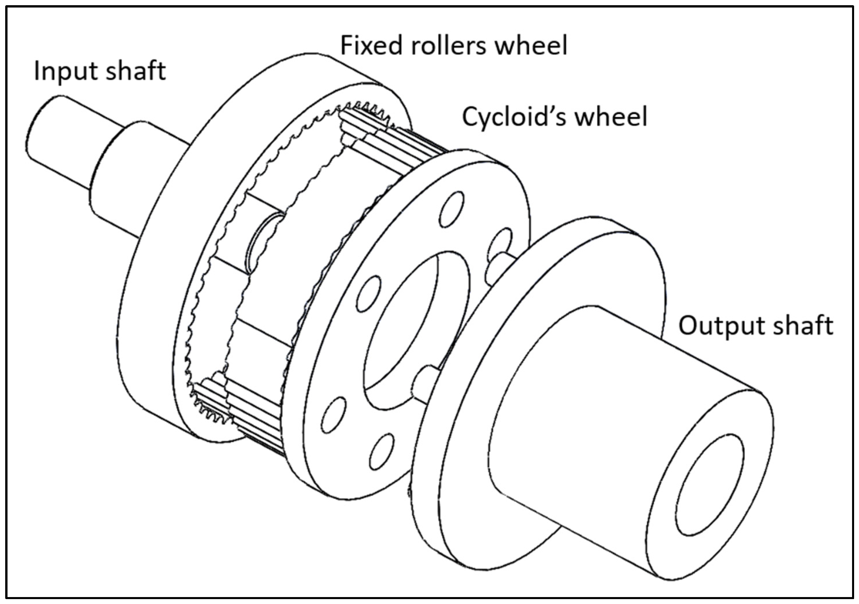
The Mono-stage has 57 rollers and 56 teeth and provides a transmission ratio of –(1/56). The main components of this configuration are shown in
Figure 1. In more detail, it is constituted by:
The input shaft that hosts the eccentric (having an eccentricity of 1 mm).
The cycloid’s wheel.
The wheel hosting the fixed rollers and the holes for the extraction of the output motion.
The output shaft that has the pins.
The main characteristics of the Mono-stage are summarized in
Table 1; the overall dimensions are 170 mm (wide) × 192 mm (length).
2.1.2. Wolfrom
The Wolfrom configuration is constituted by two reduction stages, and its main characteristic is that the extraction of the output motion is performed through the wheel that hosts the fixed rollers of the second stage. More specifically, this component is rigidly connected to the output shaft, and, thus, it rotates around its axis. The kinematic behavior and the preliminary investigation of the performance of this configuration are described in detail in [
4,
5,
6]; for the sake of brevity, here we recap just the main features. The Wolfrom allows for radically lower encumbrances and a lower number of components than those of a classical two-stage configuration, as there is no need for pin-hole transmissions between the first and second stages or between the second stage and the output shaft. This allows one to avoid some of the problems related to misalignments between pins and holes, as highlighted in [
16,
17]. The first stage has 9 rollers and 8 teeth, thus providing a transmission ratio of (−1/8), while the second stage has 8 rollers and 7 teeth, and, consequently, the transmission ratio is (−1/7). Therefore, the overall transmission ratio is (1/56) and the output shaft rotates in the same direction as the input one. In this configuration, the eccentric hosting the cycloids’ wheels has an eccentricity of 7 mm, which generates not negligible dynamic loads with respect to the Mono-stage. However, for both configurations, this problem is easily solved by inserting adequate masses on the input shafts to obtain the dynamic balance of the whole system.
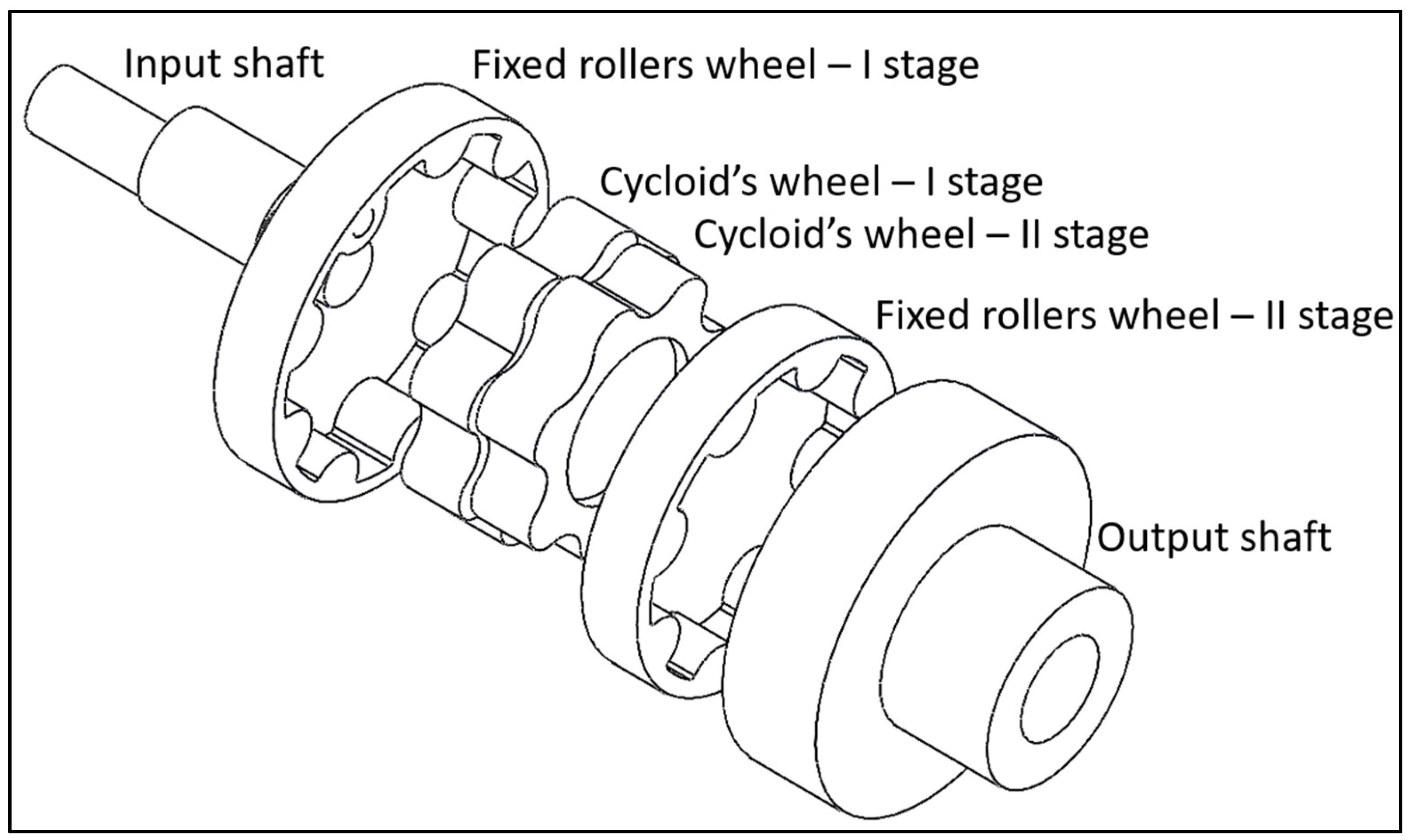
Figure 2 depicts the main components of the Wolfrom, which are the following:
Input shaft that hosts the eccentric on which the cycloids’ wheels of the first and second stage are mounted (eccentricity of 7 mm).
Cycloid’s wheel of the first stage.
Cycloid’s wheel of the second stage that is rigidly connected with the cycloid’s wheel of the first stage.
Fixed roller’s wheel of the first stage.
Fixed roller’s wheel of the second stage that is rigidly connected with the output shaft.
The main features of this configuration are summarized in
Table 2. It is worth noting that the overall dimensions are comparable to those of Mono-stage, as well as the thicknesses of rollers and teeth.
2.2. Investigation Approach
The objective of the investigation was fulfilled by simulating the mechanical behavior of the two configurations described in the previous subsection, under the hypothesis of a dimensional error
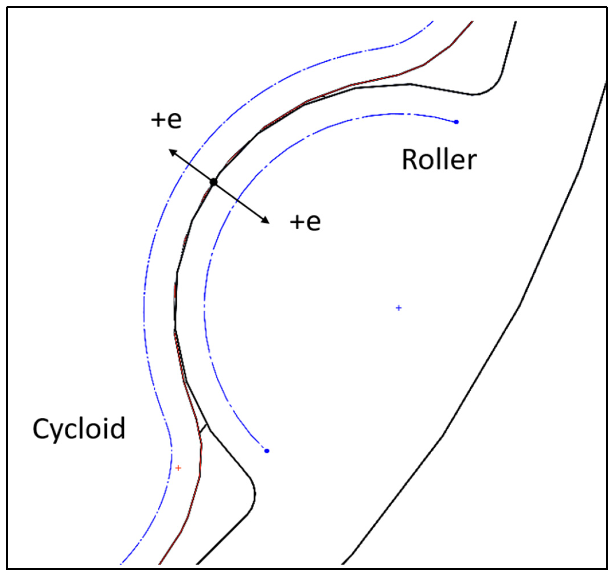
e affecting the rollers’ radius and the cycloids’ shape. The benchmark was represented by the condition with nominal dimensions. In more detail, we considered as a positive shift the error that diminishes the radius of the roller and the height of the tooth of the same quantity, as shown in
Figure 3. Negative shift was not considered, as this condition would generate interference between rollers and cycloids, with an obvious disruptive impact on the performance. The non-symmetric positive shift was neglected, as it is supposed to be less impactful than the symmetric condition.
The considered shift was 0.8 mm, which refers to a precision grade well beyond the “very coarse” for the Mono-stage (whose value corresponded to 0.5 mm), and between “coarse” and “very coarse” for the Wolfrom (whose values corresponded to 0.5 and 1 mm, respectively), according to the Standard ISO 2768. We applied this error to both stages of the Wolfrom, as the nominal dimensions of rollers and teeth were the same for the two stages. We did not consider shifts greater than the considered magnitude, the Mono-stage configuration being very close to the physical limit at which it experiences uncertain contact conditions between rollers and cycloids. This makes the simulations impossible since, very often, they do not converge on a solution.
Table 3 summarizes the considered configurations and errors (in mm).
As the considered dimensional error reduces the number of rollers and teeth that are in contact, as well as their shape, the performances against which we assessed the impact in reference to the nominal dimensions were the following:
Input Torque—is the torque seen from the side of the input shaft. As is well-acknowledged by the literature, it is also affected by the contact forces between rollers and teeth.
Torque Ripple—is the fluctuation of the input torque. The literature suggests that the torque also changes depending on the number of rollers (and teeth) in contact, which in turn affects the direction of the contact forces.
Input Energy—is the energy the input shaft provides.
Von Mises Stress—is the equivalent stress that acts on the surface of the teeth. We considered the maximum magnitude of this feature since the dimensional error affects the radius of the tooth’s surface along the contact arc, whereas the radius of the roller remains constant. The two configurations are comparable, as rollers and teeth have the same thickness to guarantee the overall encumbrance of the system imposed by the specification.
The comparison among Wolfrom and Mono-stage was performed by considering the average values of the above performances in a rotation of the input shaft. The simulation approach used to obtain the required data is described in the next subsection.
2.3. Simulation Approach
As is known, the stage of a cycloidal drive is characterized by a configuration where several teeth are in contact with rollers, and, therefore, the contact forces strongly depend on the stiffness distribution along the whole contact arc [
16]. The introduced dimensional error decreases the length of the contact arc and, consequently, diminishes the number of teeth that are in contact with the rollers in an unpredictable way. Therefore, to simulate the mechanical behavior of the system in both the Mono-stage and Wolfrom configurations, we needed an approach capable of modeling the contact stiffness and its variability along the contact arc; otherwise, the contact conditions could not be correctly determined. For this reason, we adopted the finite element method (FEM) instead of multi-body approaches. The 3D virtual prototypes of the configurations under investigation were parameterized to manage the introduced error through the radius of the rollers and an offset of the cycloids’ profiles. Furthermore, to simulate the system in different positions, we assembled the virtual prototypes in a fashion capable of managing the relative angular position between rollers and input shafts. The employed simulation code was Solidworks Simulation (release 2020), which is a tool integrated in the Solidworks suite (by Dassault Systemes). It can assist in design optimization tasks, determining the mechanical resistance and the natural frequencies, and evaluating heat transfer and buckling instabilities of mechanical systems.
According to the description of the configurations presented in
Section 2.1, the finite element models were built taking into consideration the following components:
Mono-stage—input shaft, fixed roller wheel, and cycloid’s wheel.
Wolfrom—input shaft, fixed rollers of the first stage, cycloids’ wheels, and fixed rollers of the second stage (to which the output shaft is rigidly connected).
The other components were neglected, as they play a negligible role in determining/affecting the behavior of the system, especially the contact between rollers and cycloids.
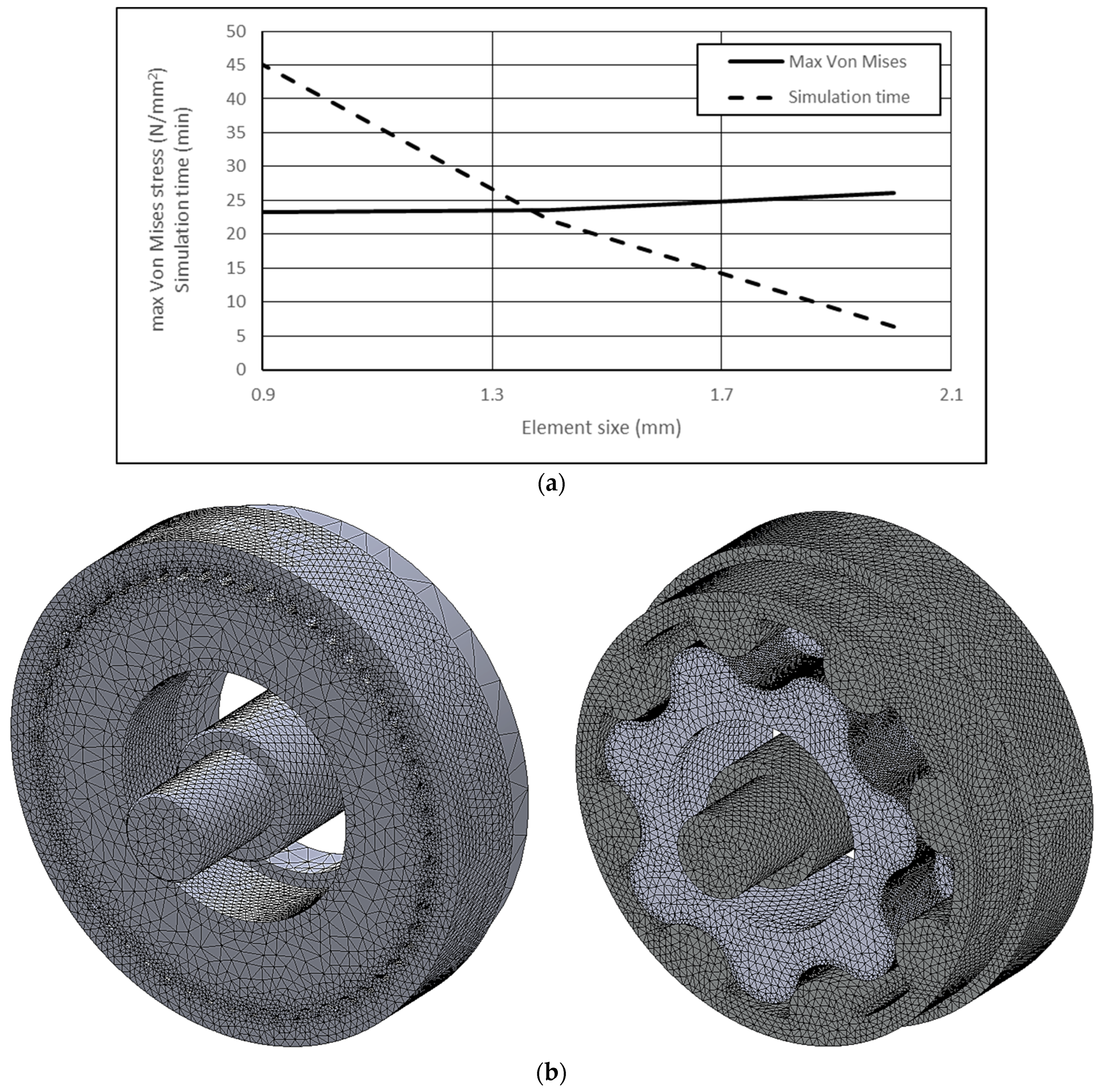
Due to the high number of simulations that the investigation approach entailed, we searched for a compromise between the time taken by the simulation task and the quality of related results. To achieve this aim, we used parabolic tetrahedral solid elements to generate the mesh, whose size was managed through transition controls that allowed the tightening of the discretization on the contact surfaces between cycloids and rollers. This aspect was particularly critical for the Mono-stage, which is characterized by small rollers and teeth. To identify a minimum element size capable of guaranteeing a good quality of the results, we performed some simulations on the Mono-stage aimed at exploring the sensitivity to the parameter of the maximum Von Mises stress. The applied constraints and load were the same, as described in the following subsection. The explored size’s range spanned from 0.9 to 2 mm, whereas values greater than 2 mm were not investigated as the model became unstable during the solving process. Furthermore, we kept track of the time the simulations took to get an estimation of the overall computational effort.
Figure 4a depicts the results of the conducted exploration. The hardware was to the following: Intel Core™ I7-9750H, 2.6 GHz processor 12 MB L3, HDD: 1000 GB, SSD: 256 GB, RAM: 16 GB. As shown, while the maximum Von Mises stress did not change significantly for an element size between 0.9 and 1.4 mm, the time required for the simulation halved. Therefore, we considered a size’s limit as 1.4 mm, as it seemed to be a good compromise between quality of the results and time effort. It is worth noting that the results are coherent with the recent literature on the topic [
19].
However, as the Wolfrom has two cycloidal stages, its FE model required a number of elements greater than the Mono-stage, since the number of components that are in contact doubles the Mono-stage. According to the selected finite element size, the FE models of the Mono-stage and Wolfrom configurations are presented in
Figure 4b and the number of nodes and elements are summarized in
Table 4. Eventually, the considered material was steel with an elastic modulus of 210,000 N/mm
2 and a Poisson’s coefficient of 0.3. The material was implemented through a linear-elastic model already available in the simulation code.
The contact between rollers and cycloids was modeled through the automatic contact search algorithm available in the simulation tool with a friction coefficient of 0.05, which refers to steel with lubricated surfaces. This contact’s modality allows one to search for contact that does not require an analytical determination of the relative angular position between the rollers, the cycloids, and the input shafts, making the whole simulation task easier and faster. This is an important requisite also considering the over-constrained nature of the studied contact, which is distributed among many teeth, making this application far more demanding with respect to known examples in the literature such as cam-follower transmissions, in which the geometry of a single contact patch is quite similar, but the overall system is not over-constrained [
20].
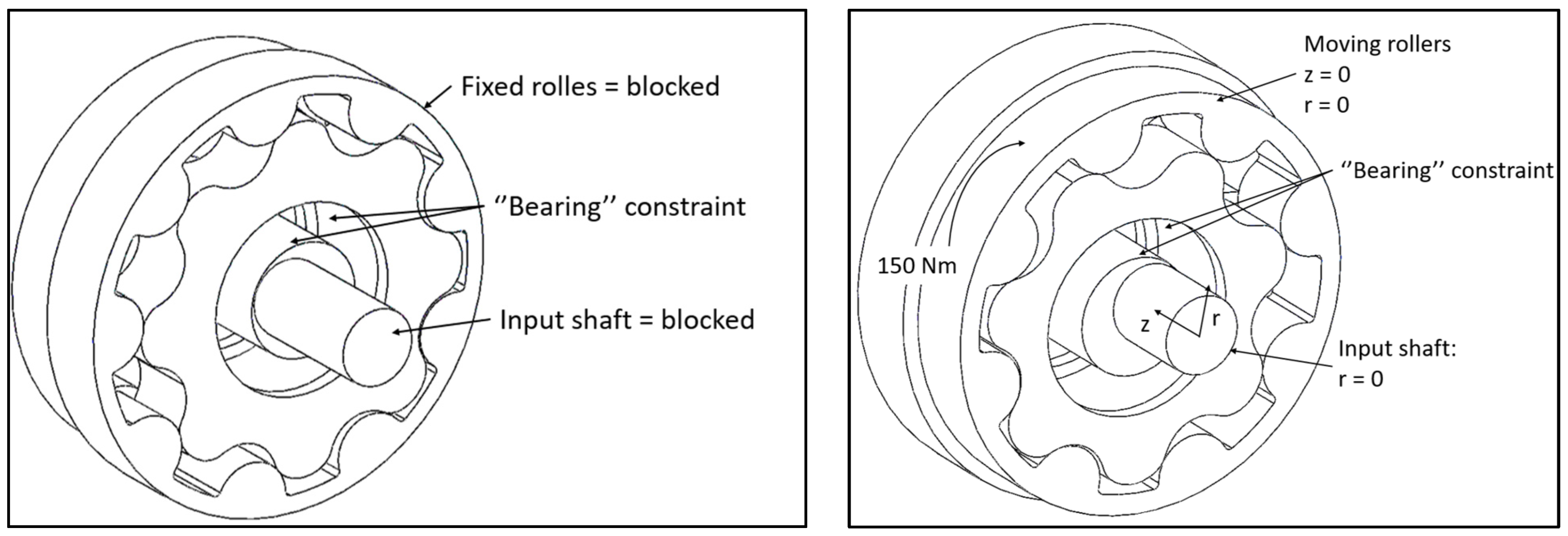
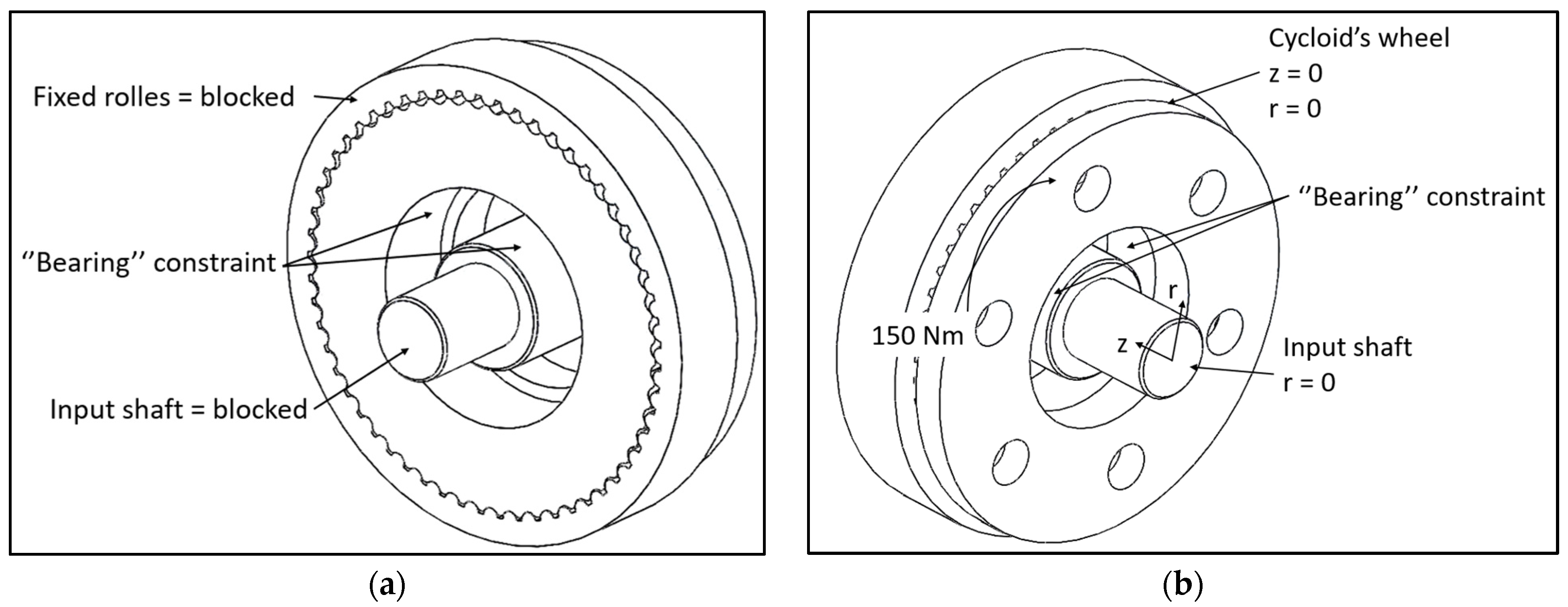
Figure 5 and
Figure 6 depict the constraints and load applied to the Wolfrom and Mono-stage, respectively. The input shafts of both configurations were constrained by blocking the rotation around their axes and the translation along the radial direction and the direction parallel to the rotation axis. The cycloidal wheels of both configurations were constrained on the input shafts by using the constraint “rigid bearing”, which can model the pivot of the bearing and block the degree of freedom related to the direction parallel to the rotation axis. The fixed rollers were constrained by blocking all the degrees of freedom, as they are fixed elements in both configurations. The applied load was a constant torque of 150 Nm, which acted on the moving rollers of the Wolfrom configuration and on the cycloid’s wheel of the Mono-stage. This load comes from the specifications defined by the company that manufactures the machines to which the cycloidal drive is dedicated.
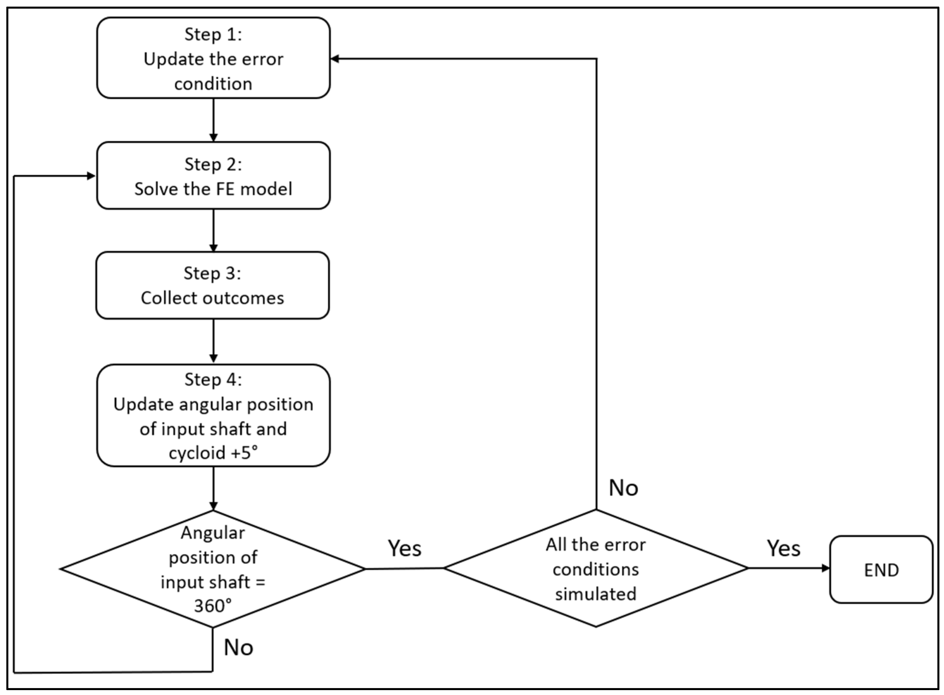
The procedure implemented to collect the expected outcomes is represented in
Figure 7 and was applied to the two configurations under study. To have a satisfactory representation of the system’s behavior, the procedure calculates the desired outcomes for 72 angular positions of the input shafts along with a complete rotation. In such a way, each angular step of the input shaft had an amplitude of 5°, which corresponds to a rotation of the cycloids equal to 0.71° for the Wolfrom and 0.089° for the Mono-stage configuration. We deemed this a good compromise between the accuracy of the representation of the system’s behavior and the required time resources. Therefore, the simulation approach took 288 simulation tasks, i.e., 1 simulation for each configuration and condition error, as summarized in
Table 1. Going into the procedure in more detail, Step 1 entailed the setting up of the considered condition’s error. This was obtained by modifying the roller radius and the geometrical parameters of the cycloidal profiles in the virtual prototype. Step 2 was dedicated to the solving process of the FE model, which entailed the meshing task and the solution of the static problem. In Step 3, the relevant outcomes of the FE analysis were extracted from the set of results and recorded on an Excel datasheet. More specifically, the torque acting on the input shaft was assessed by reading the reaction torque on the rotation constraint applied to the input shaft, whereas the maximum Von Mises stress, as already said, was probed on the surface of the cycloids. As the input torque was obtained as a function of the angular position of the input shaft, the input energy was calculated by integrating the input torque for a complete rotation of the input shaft. Step 4 updated the layout of the system in reference to the new angular position of the input shaft.
Once the input shaft assumed all 72 angular positions, the study of the condition’s error ended.
3. Results
The overall simulation task entailed the execution of 288 simulations, i.e., 144 simulations for each configuration and 72 simulations for each condition error (e = 0 and e = 0.8 mm). Each simulation lasted 20 min on average, however, the duration strongly depended on the position of the input shafts and the error condition. The simulations of the configurations corresponding to the nominal dimensions required more time, as the contact conditions were harder than those affected by the dimensional error due to the high number of rollers and teeth in contact.
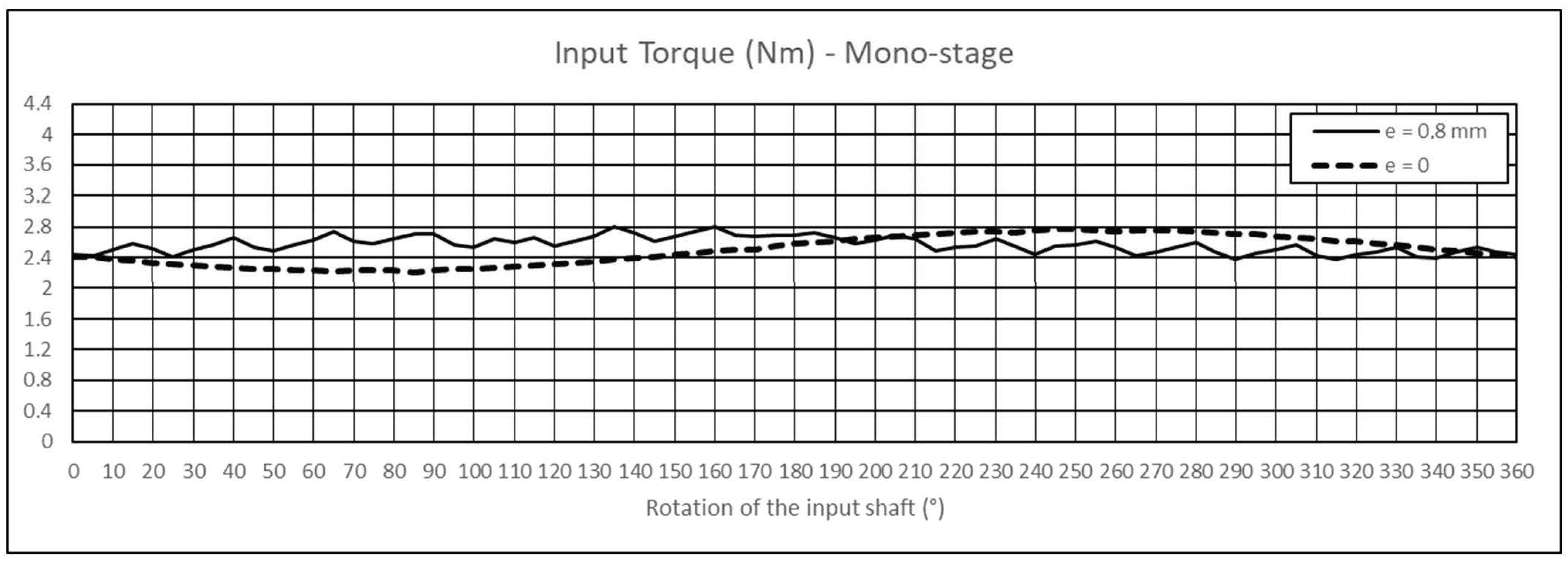
Figure 8 and
Figure 9 present the variation in the torque seen by the input shaft for the Mono-stage and Wolfrom configurations, respectively, in a complete rotation of the input shaft. Furthermore,
Figure 10 depicts the torque ripple, calculated as the difference between the maximum and minimum magnitudes of the torque. The torque of the Mono-stage varied between 2.21 and 2.78 Nm in the condition corresponding to the nominal dimensions, and between 2.38 and 2.81 Nm in that affected by the error. In the nominal condition, the torque of Wolfrom varied between 0.59 and 4.06 Nm, while in the condition affected by the dimensional error, it comprised an interval between 0.95 and 3.83 Nm. On average, the sensitivity of the torque had the behavior presented in
Figure 11 for the Mono-stage and the Wolfrom. The average input torque was calculated as the arithmetic average of the values determined in the simulated positions of the input shaft for a complete rotation.
The diagrams presented in
Figure 12 show the input energy evaluated in a complete rotation of the input shaft for the Mono-stage and Wolfrom configurations, respectively. As it is possible to see, the input energy required by the Mono-stage with the nominal dimensions was 15.7 J, while, in the condition affected by the dimensional error, the magnitude reached 16.1 J. This trend was also confirmed for the Wolfrom, which absorbed 12.1 J in the nominal condition and 13.4 J when affected by the dimensional error.
The behavior of the average maximum Von Mises stress is shown in
Figure 13 for both the Mono-stage and Wolfrom configurations. It was calculated as the arithmetic average of the maximum values that act on the surface of the cycloids, for a complete rotation of the input shafts. In the nominal condition, the mono-stage underwent a stress of 23 N/mm
2 while in the condition affected by the error, and the stress became 361 N/mm
2. The Wolfrom configuration in the nominal condition experienced a stress of 15 N/mm
2 for the first stage and 29 N/mm
2 for the second stage, whereas the stress was 28 N/mm
2 for the first stage and 40 N/mm
2 for the second stage in the condition affected by the dimensional error.
Eventually,
Table 5 presents a comparison, in percentage terms, among the Mono-stage and Wolfrom configurations in the condition affected by the dimensional error, taking as reference the condition of nominal dimensions for the percentage calculations.
5. Conclusions
The paper compares two cycloidal drive configurations, Mono-stage and Wolfrom, to investigate their behavior based on the dimensional error affecting rollers’ radius and teeth size. The sensitivity analysis measures input torque, torque ripple, energy absorption, and Von Mises stress on contact surfaces. The results show that a configuration with a large number of small teeth is more demanding in terms of input torque and energy consumption, but less sensitive to deviations from nominal dimensions. Conversely, configurations with a small number of big teeth are less sensitive to stress conditions on contact surfaces. The analysis confirms the suitability of the proposed Wolfrom configuration for applications where reducers are subjected to overloads or assembled with materials with poor structural properties and tolerances.
However, higher torque ripples can cause noise and vibrations, especially at partial loads. The paper suggests that increasing the profile offset can slightly improve this issue, but this has limited consequences on resistance.
