1. Introduction
Higher kinematic pair mechanisms, like cam mechanisms, gears, Geneva driving mechanisms (Maltese cross mechanisms), the ratchet mechanism, etc., are generally the most used in machinery and have the advantage of a superior and irreversible transmission and coupling resulting in a contact point or line but never a surface [
1]. In the sense of their optimal design for higher working efficiency in conditions of avoiding vibrations, noises, shocks, or interruptions, the dynamic phenomena must be mastered. More generally, for any kind of mechanism in machinery driving chains, a reliable prediction of the dynamic behavior working through parameters like speed, acceleration, force distributions, loss coefficient, dynamic coefficient, or motion transmission function is essential in machine design. Dynamic models, analyses, and research approaches are known regarding various kinds of mechanisms, starting from a crank piston mechanism [
2] or an oscillatory slider mechanism [
3] up to classical distribution mechanisms [
4], and ending with bionic robotic structural mechanisms [
5] or complex gear transmissions [
6].
Particularly for the cam mechanisms, which cover a large structural variety that are widely used in machinery, mainly as components of automated systems, the problem of negative dynamic phenomena appears in the presence of high inertial loads determined by the specific high velocity and acceleration rates [
7]. Particular operation of the cam mechanisms, as subsystems of machinery equipment like combustion engines, machine tools, packaging machines, textile machines, precision mechanical equipment, or medical devices [
8], is ruled by specific sets of dynamic variables depending on geometrical parameters and technological conditions. However, all the cam mechanisms have sufficient elasticity in their components to create conditions for residual vibrations in operation [
9]. Mastering the involved complex sets of structural and process variables in the sense of identification, inventory, classification, and quantification of influence factors in direct relation to operational performance parameters and further optimal adjusting of operating conditions is vital for predicting the dynamic behavior of cam mechanisms.
A synthesis review on the current state of the research field of cam mechanism dynamics highlighted several researched aspects [
10], which one may group as follows:
Research on a unified methodology for calculating the geometrical parameters and the profile curves for cams;
Optimization of basic geometrical parameters of cam mechanisms;
Research on quality criteria for the cam mechanisms in operation;
Definition of new motion laws for dynamic optimization;
Conditions determining the contact loss in cam mechanism coupling;
Loads and forces in cam mechanism operation. Problems in camshaft torsion minimization;
Shocks and vibrations in cam mechanism operation;
Dynamic models for cam mechanism research;
Dynamic comparison of cam mechanism structure;
Influence of the clearance in kinematic pair on the dynamic behavior;
Influence of the accuracy and the wear on the cam profile and the operating vibrations on the precision of the follower motion in cam-follower mechanisms.
The following types of cam mechanisms were studied concerning the methodologies for calculating the geometrical parameters and the profile curves for the cams: plane mechanisms with disk cams having external profiles or profiled grooves, with oscillating or translating followers, those having rollers or being flat-faced, and also spatial mechanisms with cylindrical cams. Tiboni et al. [
11] proposed the use of an evolutionary algorithm for the representation of the movement, and, therefore, of the cam profile, based on the modified trapezoidal motion law, also known as the modified seven segments. Faxin and Xianzhang [
12] presented a software solution developed on the VB (Visual Basic language) platform for designing the moving tracks and the cam’s profile in the case of a parallel combination of cam mechanisms.
Research studies on the optimization of basic geometrical parameters of cam mechanisms mainly approached mechanisms with disk cams and oscillating or translating followers and rollers and targeted the minimization of the cam’s dimensions and wear, imposing restrictions related to the pressure angle, the curvature radius for the cam and the follower roller, the contact stress in the coupling cam-follower, the mechanism’s overall dimensions, or the radius of tool for machining the cam profile. Mohan Kumar et al. [
13] proposed an algorithm and a software tool for designing some disk cams for single spindle automats under the limitations of the pressure angle and curvature radius. Petrescu [
14] proposed a method of geometric synthesis for the cam mechanism and translated the tappet with a roll that used only the geometric parameters without considering the velocities and utilizing a condition to realize the tappet the velocities imposed by the motion laws. Kim et al. [
15] developed a study on the optimal synthesis of a spring-actuated cam mechanism using a cubic spline, which was able to satisfy asymmetric constraints and guarantee continuous contact at the cam-follower interface. Based on a dynamic model built for a complete spring-actuated cam system, the optimized cam was compared with a cam having constant angular velocity and a polynomial cam.
For the evaluation of cam mechanism operation, a set of quality criteria have been identified and inventoried [
16]: the mechanic operation efficiency, the force multiplying coefficient, the coefficient of stiffness for mechanism parts, the coefficient of friction losses in kinematic couplings, the degree of distancing the mechanism from blockage zones, and the overall dimensions of the mechanism. Naskar and Acharyya [
17] conducted extended experimental research for measuring the dynamic response of jerk-optimized, stress-optimized, and size-optimized cams. The method adopted to measure the performance of the cam drive considered the elastic deformation of the cam surface due to induced stresses and established the causes behind the deviations of the theoretical cam displacements from the actual displacements.
A motion law that provides adequate dynamics of cam mechanisms has to deal with continuous time functions of the acceleration and the jerk that present the least possible values for the maximum acceleration. The quality criteria for the follower motion law would consider avoiding soft and hard shocks. Research studies in the direction of motion law optimization proposed solutions using polynomials, cubic spline curves, and finite Fourier series. Yoon and Rao [
18] proposed piecewise cubic spline functions for representing the follower displacement and the minimum norm principle for the general synthesis of cam motion. Müller et al. [
19] used Mechanism Developer (MechDev) as a software tool in the research on the optimization of the transmission angle and the curvature of cam mechanisms. He also applied Non-Uniform Rational B-Splines (NURBS) for modeling the angular input of a cam from a cam mechanism with a prismatic roller-follower. Nguyen [
20] used the properties of NURBS for studying the motion curves for the follower of cam mechanisms, including peak values of the acceleration and jerk, and proved advantageous characteristics compared to classical approaches.
Regarding the conditions determining the contact loss in cam mechanisms coupling, the jump of the follower under high-speed rates or vibrations has been mainly studied. Sadek and Daadbin [
21] approached the dynamic modeling of a torsion bar cam mechanism from a packaging machine, showing that the follower jumps appear mostly in the phase of positive acceleration, determined by the vibrations of the mechanism under high-speed operation. Research on the exact response of a follower system was performed by Bagci and Kurnool [
22]. The proposed method used Laplace Transforms allowing one to determine the critical cam speeds and the possible follower jump conditions. De Groote et al. [
23] used recurrent neural networks to estimate the follower jump trajectory, based on cam rotation measurements, for a wide range of operating conditions and system modifications. Their research proposed the use of an additive feature attribution method to quantify the contribution of features in a multivariate time series on the prediction output of recurrent neural network models.
Loads and forces in cam mechanism operation have been analyzed mainly for mechanisms with disk cams and translation or oscillating followers and combined cam-bar mechanisms. Camshaft torque fluctuations have been also studied, and solutions for the minimization of reactions in couplings have been proposed. Sadler and Yang [
24] applied nonlinear programming techniques to the design of systems consisting of a four-bar linkage driven by a disk cam, targeting as an objective the minimization of input torque fluctuation under the assumed condition of constant input angular velocity of the cam. Hejma et al. [
25] proposed a methodology for the calculation of torque according to the desired angular velocity of the cam. Particularly, a cubic polynomial, the fifth-degree polynomial, and the seventh-degree polynomial were studied. Jin et al. [
26] proposed a mathematical model for a roller cam rail mechanism used as a conversion mechanism in a 2D pump for avoiding sliding friction pairs and optimizing the force balance conditions in the pump at higher operating speeds. Experiments were developed to demonstrate the model’s precision and the effectiveness of the mechanism. Problems in camshaft torsion minimization were also approached by Guilan et al. [
27], who proposed a solution to install a flywheel on the output shaft of an additional cam linkage mechanism to producing an opposite kinetic energy fluctuation that can counteract the effect of the energy fluctuation.
Research studies highlighted that in cam mechanism operation, a motion law with finite discontinuities of speed may determine hard shocks, and a motion law with finite discontinuities of accelerations may determine soft shocks. Vibrations in cam mechanisms have been studied in relation to the motion law, the elasticity of the mechanism, the fluctuations of cam speed, etc. Considering oscillations of both the cam drive system and the follower, Ambardekar and Gupta [
28] proposed an optional control to the cam input designed to minimize positional error in the output. The cam motion is stochastically simulated and analyzed. Hsu and Pisano [
29] proposed a distributed parameter dynamic model to investigate the dynamic responses of a finger follower cam mechanism. The model considers a hydraulic lash adjuster with an oscillating pivot, and also the frictional forces between the sliding surfaces. Liu [
30] applied Finite Element Analysis (FEA) for an elastic slider crank follower linkage, considering the elastic deflections induced by the large inertia of the linkage operating at a fluctuating high speed of the driving cam.
Together with those methods presented above, several other dynamic models for cam mechanisms research can be nominated. Dresner and Barkan [
31] performed a brief review of the literature on the dynamic analysis of flexible cam-follower systems, highlighting the following goals: predict when and if the follower jumps off the cam, determine the cam contact forces and the linkage forces, establish the closing spring requirements, determine the magnitude of any follower impact with its seat, and help optimize the system’s dynamic response. They also recommended a method for the analysis of such systems and an extension of this analysis method to multi-input systems. Wang [
32] proposed a model based on FEM (Finite Element Method) in time for the vibrating elastic mechanisms with clearances, where the periodic response is described in terms of a set of temporal nodes of all spatial degrees of freedom in the system. The model is applied in the study of a cam-driven valve train. Paradorn [
33] developed a three-mass, two-DOF (degrees of freedom) dynamic model for the simulation of a controlled impact and over-travel cam-follower mechanism, specific to automatic assembly machines. A two-step mesh stiffness model for the active and dwell periods, a torque compensation cam (TCC), and a torque compensation flywheel (TCF) was proposed by Kuang et al. [
34] to investigate the correlation between the dynamic response of a globoid cam (GC) system and the motor driving speed. Desai and Patel [
35] used Excel sheets to perform a complete kinematic and dynamic analysis of the cam and follower mechanisms, and critical angular speed was determined for each design to predict when the follower jumps off the cam. The analytical method was used, and the dynamic force analysis determined the cam contact forces and values of kinematic parameters at which the design fails. Zhang et al. [
36] performed a dynamic simulation for a cam-follower mechanism on a model developed using ADAMS software using a virtual prototype built in Pro/E. MSC ADAMS software was also used within a dynamic analysis on a virtual model for a cam-follower mechanism by Delyová et al. [
37], who proposed the method of reducing weight and force value on a moving member of the mechanism in dynamic modeling. Jomartov [
38] used SimulationX software environment to develop a multi-body dynamic model for the Russian Sulzer loom STB considering the transition processes, the backlash at the joints and nodes, the force of resistance, and the electric motor performance. Based on the principle of equivalent substitution of components, Deng et al. [
39] proposed a dynamic virtual model for the cam linkage mechanism from the push device of a chocolate packaging machine. The dynamic analysis within MATLAB/Simulink software, considering the elastic deformation of the member, highlighted an important effect of the lateral deformation of the camshaft on the cam motion. Jiang et al. [
40] modeled the relationship between the cam profile and the actuation trajectory and applied the cubic spline interpolation method in the cam profile generation; the study approached the case of a gravity-driven tricycle.
A dynamic comparison of the cam mechanism’s structure was researched by Vo and Le [
41]. They analyzed the dynamic response of an innovative quasi-zero stiffness pneumatic vibration isolator (QZSPVI) using two mechanisms, including a wedge and a semicircle cam. The results of the study highlighted the advantages of the proposed model against the equivalent pneumatic vibration isolator (EPVI), which had only the wedge mechanism in its structure.
The influence of the clearance in kinematic couplings on the dynamic behavior of cam mechanisms has been studied by several research investigations. Osman et al. [
42] analyzed the dynamic behavior under vibrations for a mechanism with a disk cam and a translating follower by considering the clearances in the rotation coupling of the cam and the rotation coupling roller follower in comparison with the situation of neglecting the clearances. The results proved important modifications for the accelerations, the reaction forces, and the torque on the camshaft. Wang [
32] analyzed the influence of the clearances from a distribution mechanism with a cam and a translating flat-faced follower and showed that the clearance between the valve and its seat determines impact between the valve and its seat, loss in the follower-cam contact, and impact between the follower and the cam. Chang et al. [
43] proposed a new fault diagnosis method in relation to the clearance and recoil of the cylinder cam mechanism. The method is based on the Variational Box Dimension Kernel Fuzzy Mean Clustering Algorithm (VK algorithm), which combines the variational mode decomposition and fractal box-counting dimension (VMD-FBCD), and the fuzzy clustering algorithms were determined with a kernelized Mahalanobis distance (KMD-FC).
The precision of the follower motion in cam-follower mechanisms was also studied in relation to the influence of the accuracy and of the wear on the cam profile and the operating vibrations. Rao [
44] defined the flexibility error as the difference between the desired output motion and the real one for the follower, which was determined by the inertia and the elasticity of the mechanism. His research separated the flexibility error from the mechanical and structural errors and proposed a method to calculate the elasticity of the contact spring or the mechanism for the minimization of flexibility error. Lassaad et al. [
45] investigated the nonlinear dynamic behavior and the influence of the cam profile error on it for a cam mechanism with an oscillating roller follower. The analysis is based on a nonlinear lumped-mass model including eight degrees of freedom with two nonlinear Hertzian contacts. The model was described by second-order differential equations, which were solved by using the implicit Newmark algorithm combined with the Newton–Raphson iterative scheme. De Groote et al. [
46] presented a hybrid model architecture consisting of a close interconnection of neural and physics-based network layers, which can accurately simulate the system behavior and estimate the set of critical system parameters that lead to hazardous jump phenomena in cam-follower systems. Lin et al. [
47] considered the machine undercutting, the roller limit load, and the contact stresses within a dynamic analysis of a compact cam reducer, which can be used as a rigid drive mechanism, proposing an optimal design through adjustment of the cam size, turret dimension, eccentricity, and roller size. Flocker [
48] proposed and studied a modified trapezoidal cam profile with an adjustable forward and backward acceleration, suitable for the single-dwell cam and follower applications. Follower acceleration determining the interface forces was discussed as one of the primary factors affecting the cam wear and the follower jump phenomena.
By analyzing the above considerations on the current state in the research field, the need for extended research on the dynamic behavior of cam mechanisms with bilateral higher kinematic pairs, and oscillating followers when considering the shocks resulted in contact loss and contact restauration, and the influence of cam equilibration or the influence of generalized mass, was highlighted as a current problem.
Within the various types of research on the dynamic behavior of cam mechanisms, the purpose of this study is to address the need to clarify the influence of geometrical parameters and technological conditions on some indicators of the jump phenomenon in contact loss for a cam-follower mechanism.
The research purpose derived a set of particular objectives as follows: the development of reliable dynamic models for the studied type of mechanism, testing and validation of the models through numerical simulation using customized developed software tools, FEA analysis on the coupling contact, and experimental testing and validation.
2. Materials and Methods
The particularly developed research referred to a mechanism with a profiled grooved disk cam and oscillating follower with a roller, which represented a sub-assembly of an automated feeding system from a textile machine and, more precisely, a part of the driving kinematic chain of the yarn catcher from a weaving loom machine type STB-216 (Russian product under Sulzer licence). Several types of cam mechanisms are included in the automation structure of such loom machines [
38,
49].
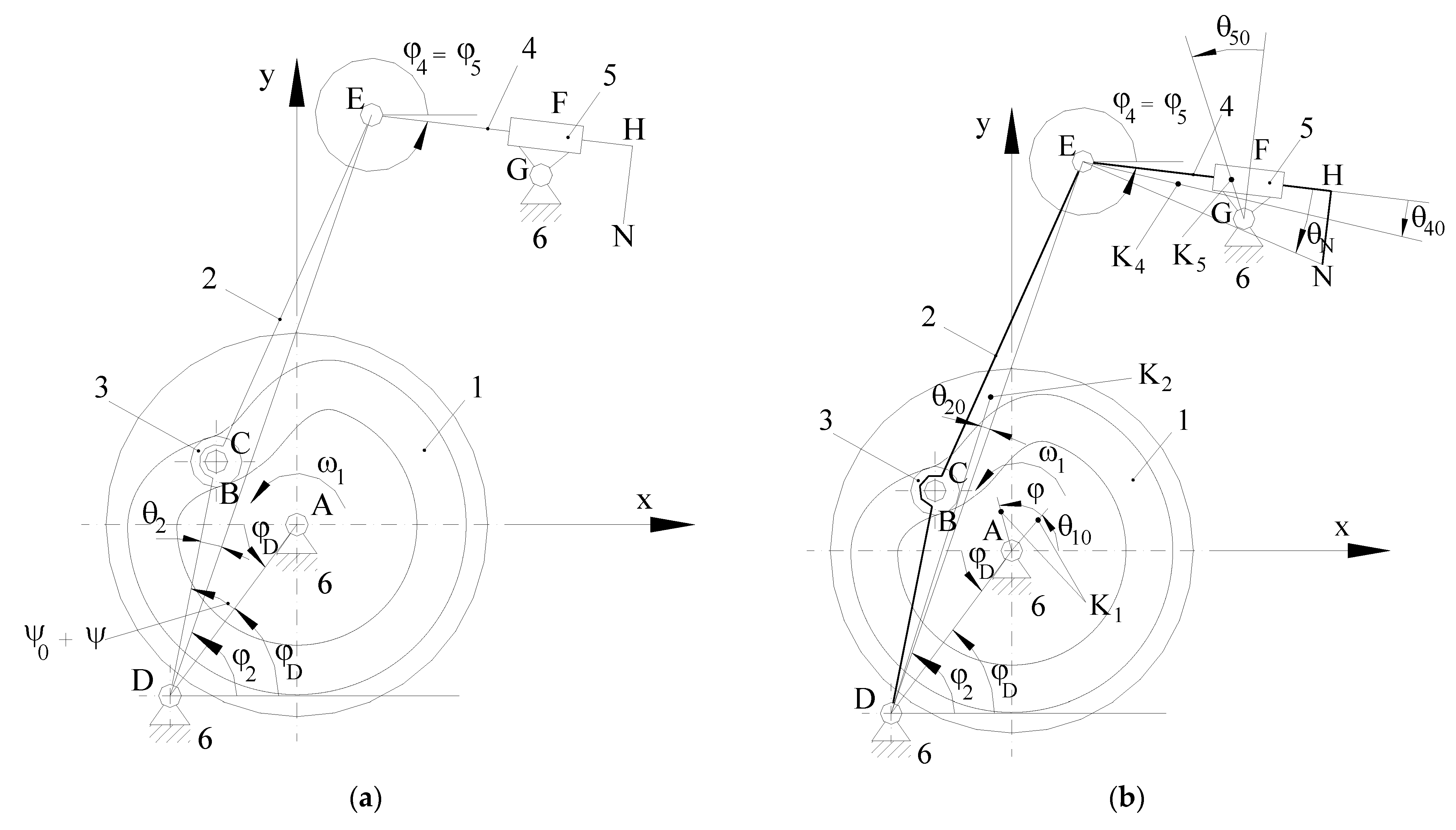
The kinematic diagram of such a mechanism is shown in
Figure 1a, where the kinematic elements of the mechanism are as follows: 1 is the cam, 2 is the follower, 3 is the follower roller, 4 is a slider (the yarn catcher), 5 is a slide block, and 6 is the fixed element (frame). The other symbols in
Figure 1a represent A, B, C, D, E, F, G, H, and N, which are the characteristic points in the geometrical calculation diagram,
fi is the angular position of the kinematic element
i,
ωi is the angular velocity of kinematic element
i,
ψ0 is the minimum angle for the follower, and
ψ is the angular displacement of the follower.
Figure 1b shows some additional geometrical elements used in calculating the developed dynamic models, and K
i is the mass center for the kinematic elements
i and
θi0 is the angular position of the mass center for the kinematic element
i.The particular values for the dimensional parameters of the mechanism presented in
Figure 1 are as follows: the diameter of the disk cam is D = 120 mm, the distance between the axis of the cam and the axis of the oscillating follower is AD =
d = 69 mm, the length of the oscillating follower is DC =
l = 61 mm, the follower roller radius is
R = 8 mm, the length of the kinematic element 4 is EH = 215.5 mm, the positional distances are DE = 186 mm, FG = 13.75 mm, and AG = 132 mm, and the positional coordinates are
xD = −34.07 mm,
yD = −60 mm,
xG = 71.5 mm, and
yG = 110.9 mm. We also mention that the minimum value of the real profile on the cam groove is
rr min = 24 mm and the maximum value of the real profile on the cam groove is
rr max = 40.428 mm. Furthermore, the rotation speed for the cam is in the range
n = 180 ÷ 240 rev/min, which means that the angular velocity for the cam,
, is in the range
ω = 18.85 ÷ 25.13 rad/s.
2.1. Dynamic Models
The influence of the cam-follower contact elasticity on the jump phenomenon was researched based on the idea to develop two dynamic models: one considering rigid elements in contact and the second considering elastic cam-follower contact [
50].
2.1.1. Dynamic Model with Rigid Elements
The first proposed dynamic model with rigid elements was developed as a reducing element model with the cam being chosen as a reducing element in the case of operation without jump (the backlash in the pair cam-follower would be j = 0).
Theoretical conditions in modeling considered a set of simplifying hypotheses based on the following assumptions:
The masses and the inertia moments of the kinematic elements of the driving chain from the electrical motor up to the camshaft were neglected;
The friction in kinematic couplings was neglected;
The rotational kinetic energy for the follower roller was neglected;
If backlash j is nonzero, the jump of the follower occurs when the reaction force R13 between the cam and the follower becomes equal to zero or it changes its sign;
During the follower’s jump, the cam and the motor move together, and independently of them, the follower moves together with the kinematic elements linked to it;
The impact between the cam and follower that occurs when the follower comes in contact with one of the flanks of the profiled groove of the cam was considered perfectly elastic and instantaneous.
For the jump period, the dynamic model of the mechanism has 2 DOF (degrees of freedom). The motor and the cam were modeled by a dynamic model-reducing element, with the cam considered as the reducing element. The dynamic model-reducing element for the follower with the elements linked to it considered the follower as the reducing element.
Under such circumstances, the differential equation of motion for
j = 0 was written as follows:
where:
The physical quantities that appear in Equations (1) and (2) are as follows:
Jred is the inertia moment reduced to the cam,
vKi is the velocity of the mass center of the kinematic element
i,
vC is the velocity of the mass center of the follower roller,
ωi is the angular velocity of the kinematic element
i,
ωm is the angular velocity of the motor,
mi is the mass of the kinematic element
i,
Ji is the inertia moment of the kinematic element
i defined related to an axis perpendicular to the plane of motion and passing through the mass center of the element
i,
Mmred is the driving moment reduced to the cam,
Mrred is the resistant moment reduced to the cam,
Gi is the gravity force of the kinematic element
i,
Fu is the load acting on the kinematic element
4,
vN is the velocity of point N where the force
Fu was applied, and
M1 is the driving moment acting on the camshaft, given by Equation (3).
In Equation (3), it is the transmission ratio from the motor to the camshaft, Mn is the nominal moment of the motor, ωn is the nominal angular velocity of the motor, and ωs is the synchronism angular velocity of the motor. Equation (3) was derived considering the linear portion of the stabile operation, under load, of the characteristic of the three-phase asynchronous motor.
For the jump period, the differential equation of motion for the cam became:
where:
and
Mmred is given by Equation (2). Similarly, for the follower, during the jump:
where:
The velocity of the cam and the follower, immediately after the impact, were determined using the Lagrange equations for the impulsive motion of a system with 2 DOF and the equation from Newton’s hypothesis. So, for the dynamic model of the cam:
and for the dynamic model of the follower:
where
J’red,
J’’red are given by Equations (4) and (6), respectively,
ω10,
ω1 are the angular velocities of the cam before and immediately after the impact, respectively,
ω20,
ω2 are the angular velocities of the follower before and immediately after the impact, respectively,
and
are the interior percussions acting on the cam, and on the follower in the cam-follower contact point,
and
are the moments of percussions,
and
, with respect to points
A and
D (see
Figure 1),
v0C12n and
vC12n are the relative velocities of point
C from the follower (
C2) with respect to point
C from the cam (
C1) before and after the impact, which are projected on the common normal direction at the cam profile, and
k is the coefficient of restitution (impact elasticity). For perfectly elastic impact,
k = 1.
The angular velocities of the cam, the follower after impact, and the interior percussions
or
resulted in the following equation:
where the notations
A1 and
A2 represent the following equations:
The dynamic model involved systems of nonlinear second-order differential equations with variable coefficients. The mathematical solving required numerical integration, and the Newton–Raphson method was applied.
2.1.2. Dynamic Model with Elastic Contact
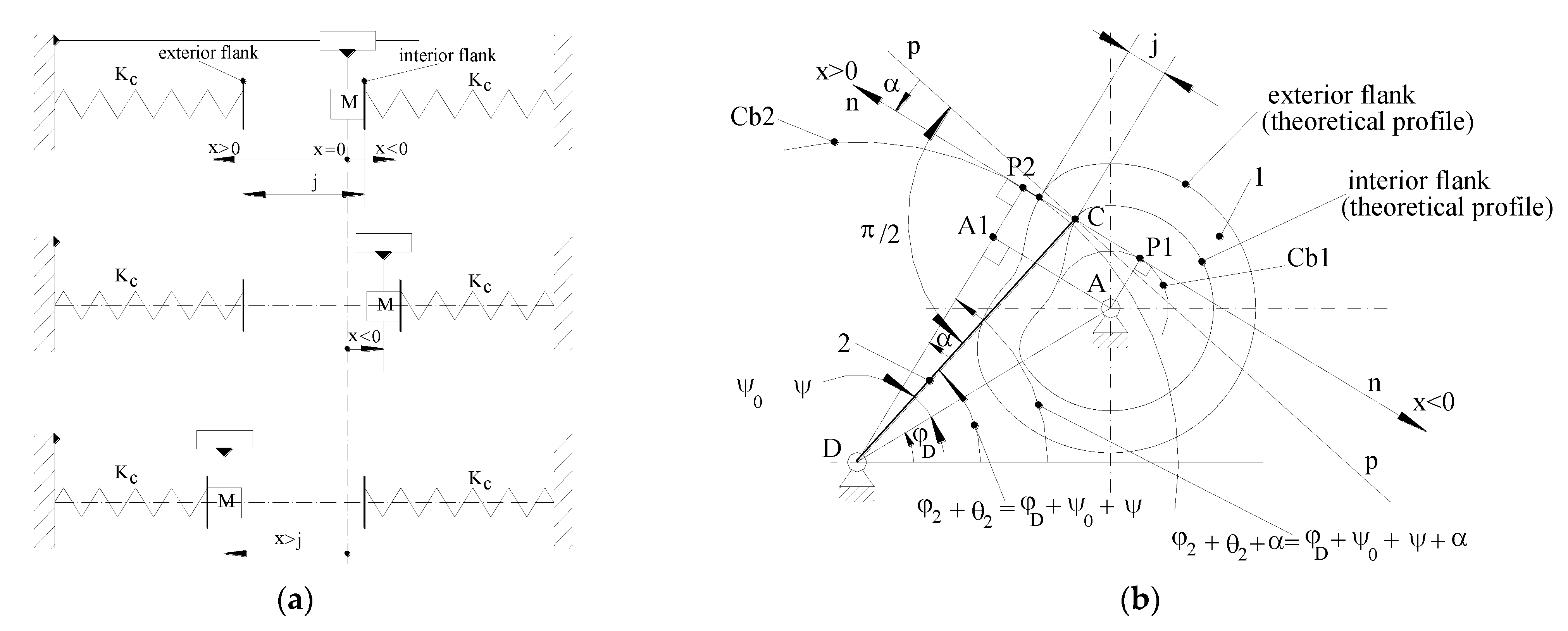
The second proposed dynamic model with elastic contact was developed as a dynamic model with 1 DOF (degree of freedom), as presented in
Figure 2.
Theoretical conditions in modeling considered a set of simplifying hypotheses based on the following assumptions:
Only the elasticity of the contact cam-follower was considered, and the other elements of the mechanism were considered rigid;
A relative motion occurs between the cam and the follower along the common normal direction at the contact point;
As a criterion to detect the jump of the follower, the relative displacement cam-follower was used. When the relative displacement becomes equal to zero or changes the sign, the jump occurs.
In
Figure 2a, the symbols are as follows:
M is the reduced mass of the mechanism (kg);
j is the backlash in the higher pair cam-follower (mm);
x is the relative displacement cam-follower along the common normal direction at the contact point (mm); and
Kc is the rigidity of the contact cam-follower (N/mm). The origin of the
x-axis was chosen in the contact point C of the follower with the interior flank of the cam (see
Figure 2b). The positive sense of the
x-axis was chosen for the exterior of the cam, and the negative sense was for the interior of the cam. The other symbols in
Figure 2b are shown according to those in
Figure 1.
The differential equations for the relative motion cam-follower were written as follows:
For contact with the interior flank (
x ≤ 0):
For the follower jump (0 <
x<
j):
For contact with the exterior flank (
x ≥
j):
In Equations (12)–(14), the other parameters are as follows:
R31 is the static reaction of the cam on the follower (neglecting friction),
t is the time (s), and
n is an exponent corresponding to the elastic force of contact
Felc (N), which was the calculated function of the contact deformation
x, as shown below [
51]:
where
lw is the length of the contact between the cam and the follower roller (mm).
Also, in Equations (12)–(14),
M is the reduced mass of the mechanism, which is given by:
where
M1 is the reduced mass of the cam (kg),
M2 is the reduced mass of the follower (kg), and
Jcam and
Jfollower are the inertia moments for the cam and the follower, which are given by the following formulas:
where
Jr1 is the moment of inertia of the cam reduced to the cam,
Jrm is the moment of inertia of the motor reduced to the cam,
Jr2 is the moment of inertia of the follower reduced to the follower,
Jr4 is the moment of inertia of kinematic element 4 reduced to the follower,
Jr5 is the moment of inertia of kinematic element 5 reduced to the follower, and
Jr3 is the moment of inertia of the follower roller reduced to the follower.
Also, in Equation (16),
Db1 is the diameter of the circle with the center in A, which is tangent to the common normal
n-n (see
Figure 2b), and
Db2 is the diameter of the circle with the center in D, which is tangent to
n-n (see
Figure 2b) and is given by:
where
l is the length DC of the follower,
d is the distance between the cam axis and the follower axis AD (see
Figure 2b), and
α is the pressure angle of the mechanism.
Once the relative displacement cam-follower
x was calculated, the position angle
φ2nel and the angular velocity
ω2nel for the follower could be calculated from the motion law of the cam, with the formulas:
2.2. Numerical Models Solving and Simulated Experiment Conditions
Numerical integration of the motion equations corresponding to the above-presented dynamic models, together with numerical simulation for virtually testing the models, were performed using a customized engineering software package developed by modular, procedural programming under a MATLAB® environment.
The input numerical data in the numerical calculation were, in relation to
Figure 1 and
Figure 2, as follows:
l = CD = 61 × 10
−3 (m), DE = 186 × 10
−3 (m), FG = 13.75 × 10
−3 (m),
xG = 72 × 10
−3 (m),
yG = 111 × 10
−3 (m),
xD = −34.073 × 10
−3 (m),
yD = −60 × 10
−3 (m),
φD = 60.408°,
ψa = 15°,
ψo = 27.627°,
φu = 58°,
m1 = 2.6271 (kg),
J1 = 2278.84 × 10
−6 (kg·m
2),
m2 = 0.3681(kg),
J2 = 1161.71 × 10
−6 (kg·m
2),
m3 = 0.0075 (kg),
m4 = 0.1266 (kg),
J4 = 905.444 × 10
−6 (kg·m
2),
m5 = 0.0474 (kg),
J5 = 9.2201 × 10
−6 (kg·m
2),
Jm = 0.007 (kg·m
2), AK
1 = 0.6796 × 10
−3 (m), DK
2 = 76.4865 × 10
−3 (m), EK
4 = 155.859 × 10
−3 (m),
θ40 = −2.087129°, GK
5 = 9.8297 × 10
−3 (m),
θ10 = 181.939487°,
θ20 = 1.408967°,
θ50 = 0°, EN = 265.0226 × 10
−3 (m), and
θN = −9.995456134°. The workload
Fu acting on kinematic element 4 in point N (see
Figure 1) was considered to have the components
Fux =
Fu and
Fuy = 0, opposing at any moment to the relative translating motion of kinematic element 4 in relation to kinematic element 5. A 3-phase asynchronous electric motor witha nominal power of
Pn = 1.1 (kW), a synchronism rotation speed of
nsm = 1000 (rpm), and a nominal rotation speed of
nm = 920 (rpm) was considered in the calculation.
For virtually testing the developed models and highlighting the influences of the geometrical parameters and the technological conditions on the dynamic behavior of the studied mechanism, numerical simulations were performed within a simulated experiment, which were organized on a 24 plan.
As influence factors, the following were considered: the applied load (load force) Fu, the backlash j in the bilateral higher kinematic pair cam-follower, the rotation speed n1 of the cam, and the inertia moment Jt of the follower and all kinematic elements linked to it, which were reduced to the follower.
Numerical simulation studied two laws of motion: the law of motion with sine acceleration and the law of motion with cosine acceleration. The calculation was performed only for the rising phase of the follower.
Again, two different situations for the angular velocity ω1 of the cam were studied: the ω1 variable, resulting from integrating the motion equation of the dynamic model, and the ω1 = constant.
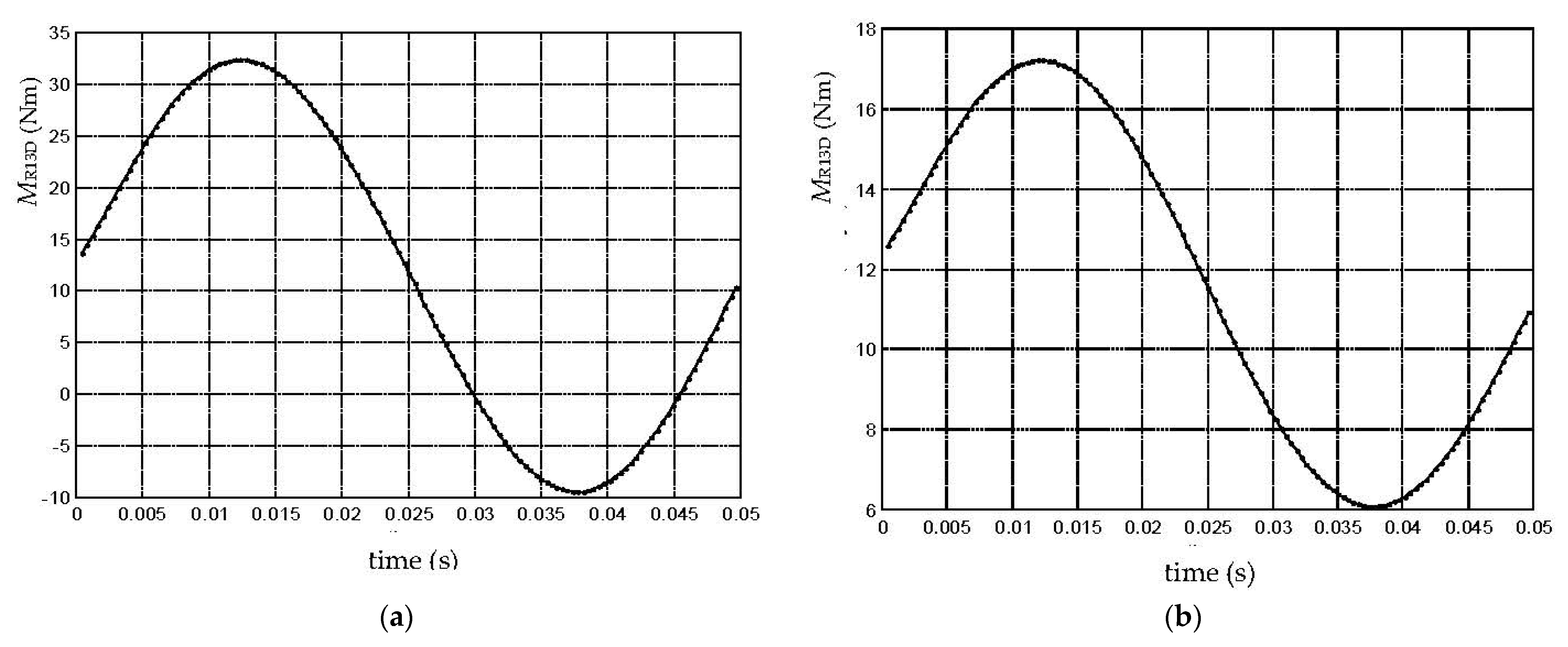
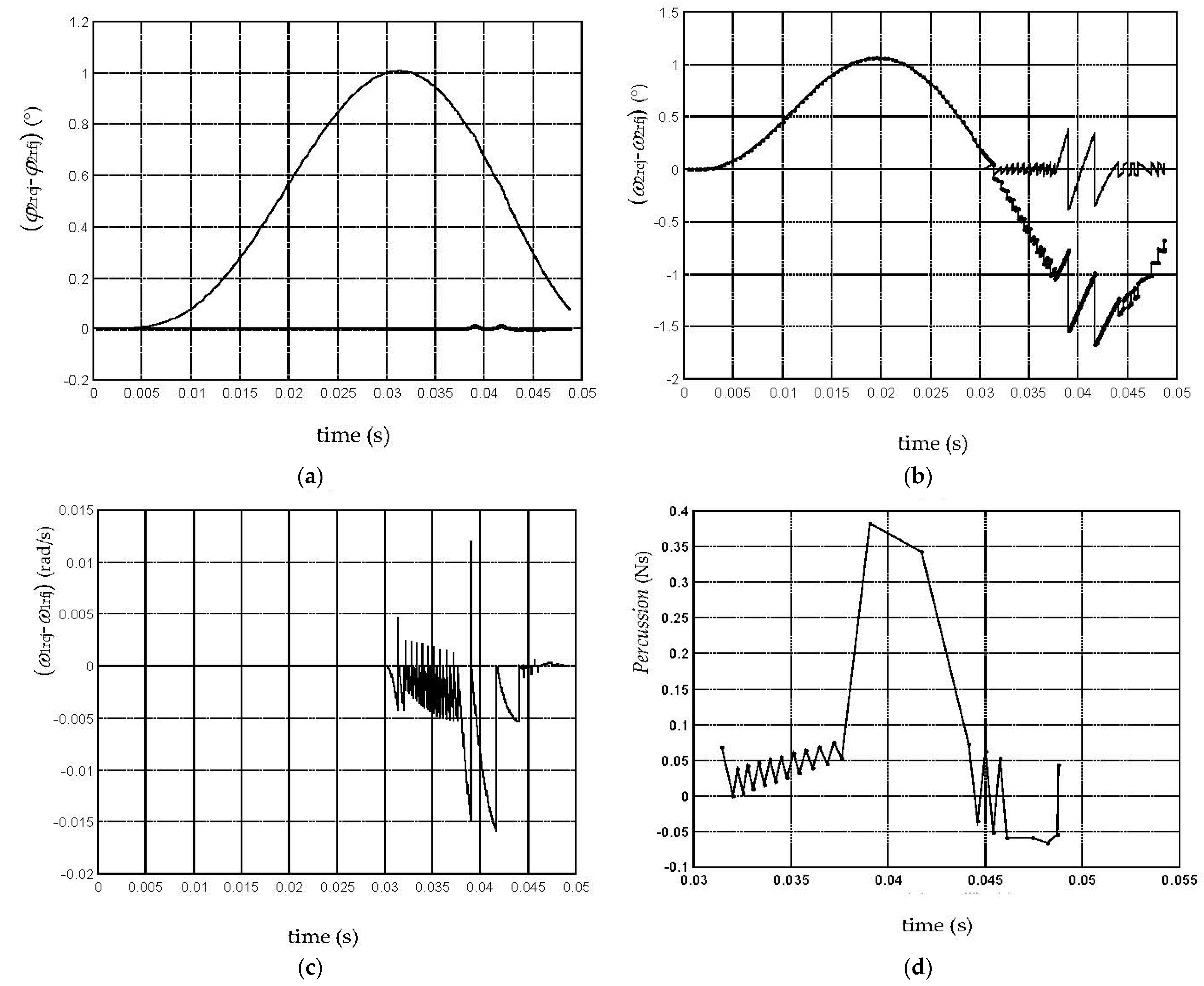
For the dynamic model with rigid elements, the following parameters were considered as indicators for the jump phenomenon: the moment (MR13D)max of the cam-follower reaction, the deviation (φ2rcj-φ2rfj)max of the follower’s angular position determined by the backlash, the deviation (ω2rcj-ω2rfj)max of the follower’s angular velocity determined by the backlash, the deviation (ω1rcj-ω1rfj)max of the cam’s angular velocity determined by the backlash, the percussion (Percussionint)max at cam-follower impact, and the number of jumps (Jumps no.) for the follower on the ascending phase.
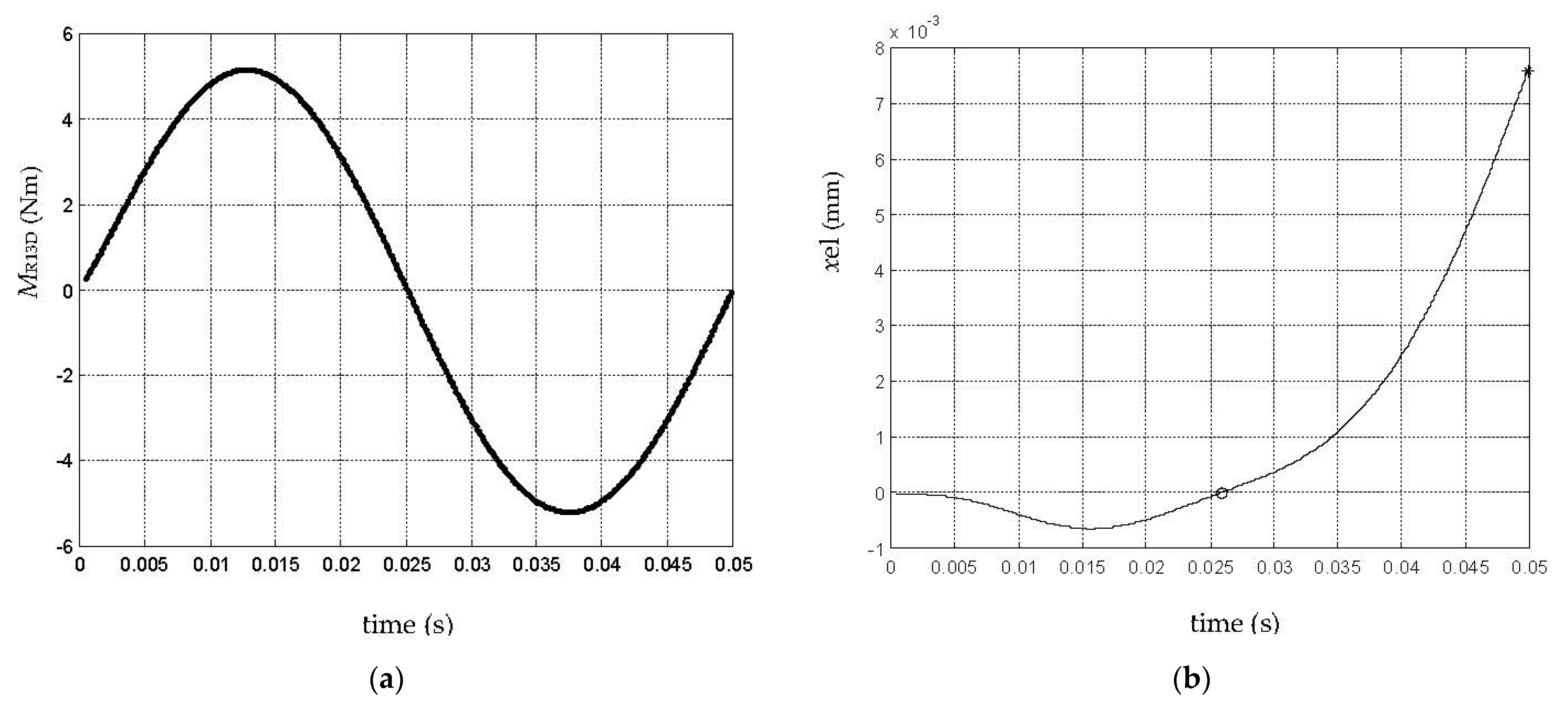
For the dynamic model with elastic contact, the following parameters were considered as indicators for the jump phenomenon: the moment (MR13D)max of the cam-follower reaction, the relative displacement of the follower in relation to the cam (xel)max, and the number of jumps (Jumps no.) for the follower.
The values of the two considered levels for the input factors within the simulated experiment are shown in
Table 1.
2.3. Finite Elements Analysis on the Contact in the Cam-Roller Coupling
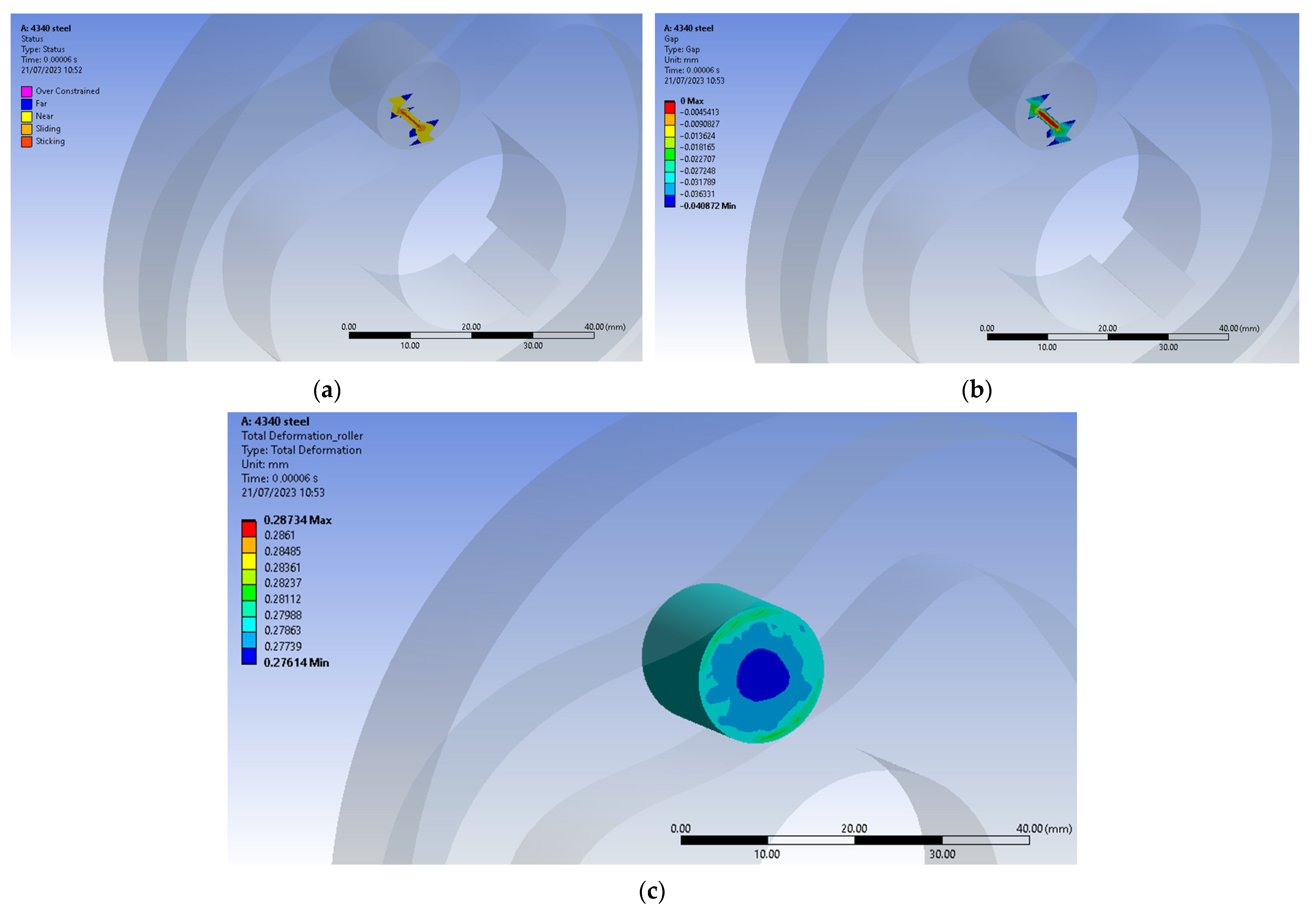
An FEA (Finite Elements Analysis) on the contact in the coupling cam-roller was also performed for virtual testing of the dynamic models. Due to limited computing power, the CAE model was simplified to the cam and roller only since the results were based on the interaction between the two. The purpose of the FEA approach was to replicate, in the CAE (Computer-Aided Engineering) model, the relative motion inside the cam-follower assembly, with conditions similar to those considered within the theoretical research that were previously described by the dynamic models and numerically simulated under a MATLAB® environment. That was expected to lead in simulation to a full interaction between the components in contact between the follower roller and the cam groove flank, and even to determine small gaps corresponding from the follower jumps of similar amplitudes to those predicted by the results of the numerical simulations. Ansys® was chosen as the FEA software tool.
For modeling the full motion of the follower roller along the imposed path on the cam profile, a 3D CAD assembly model was designed in Siemens SolidEdge
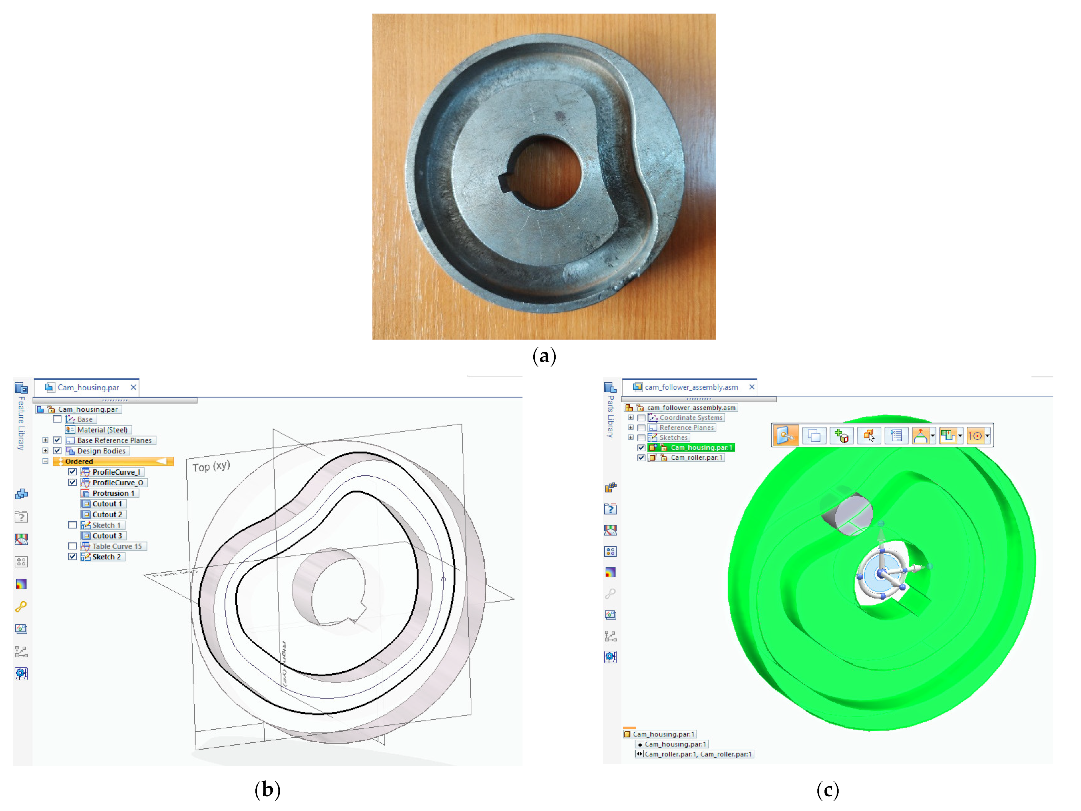
®. The internal and external profile curves from the real cam (see
Figure 3a) were generated using the
Curve by Table modeling command under the
Surfacing toolbar, as shown in
Figure 3b. Each profile curve was defined by a set of points; the corresponding coordinate calculated data was imported from an MS Excel datasheet. The 3D model in
Figure 3a corresponds to the cam profile with the law of motion with sine acceleration. A supplementary curve was defined in the 3D cam model to define the middle path of the roller in the assembly model and properly place the roller in the desired initial position. The cam and the follower roller were constrained in the assembly model using the
Path option under the
Cam Design capability, as shown in
Figure 3c. The assembly CAD model was saved in
Parasolid format to be imported as geometry data in the Ansys CAE model.
The FEM (Finite Element Method) analyses were carried out under the
Ansys Transient Structural module. The two imported part components were assigned with the 4340 type of steel, which can be found inside Ansys’s material library. When in function, after many cycles, the assembly produces hardened surfaces, which can withstand higher tensile strengths and display improved fatigue resistance. Due to its similar mechanical properties, the 4340 steel was the choice to make without the need for any external files from another material database. The motion of the follower roller had to consider a set of more than 720 data lines, including each point composing the entire path on the cam profile. In response, a new coordinate system, assigned only to the follower roller and having the same direction for each axis as the global one, was inserted in the CAE model. Connections in the model included contacts and joints. In the contacts branch, frictionless contact between the outer surface of the follower roller was set on both the lower and upper surfaces of the cam groove. The behavior of the contact between surfaces was set as asymmetric. The formulation of the contact was set to
Augmented Lagrange with the option to update stiffness with each iteration, and there was no stabilization damping factor. The interface treatment was set to adjust for touch at all times. The
next contact pair was assigned to the back of the follower roller and the corresponding surface of the cam groove. This component was later grounded inside the joint branch. The
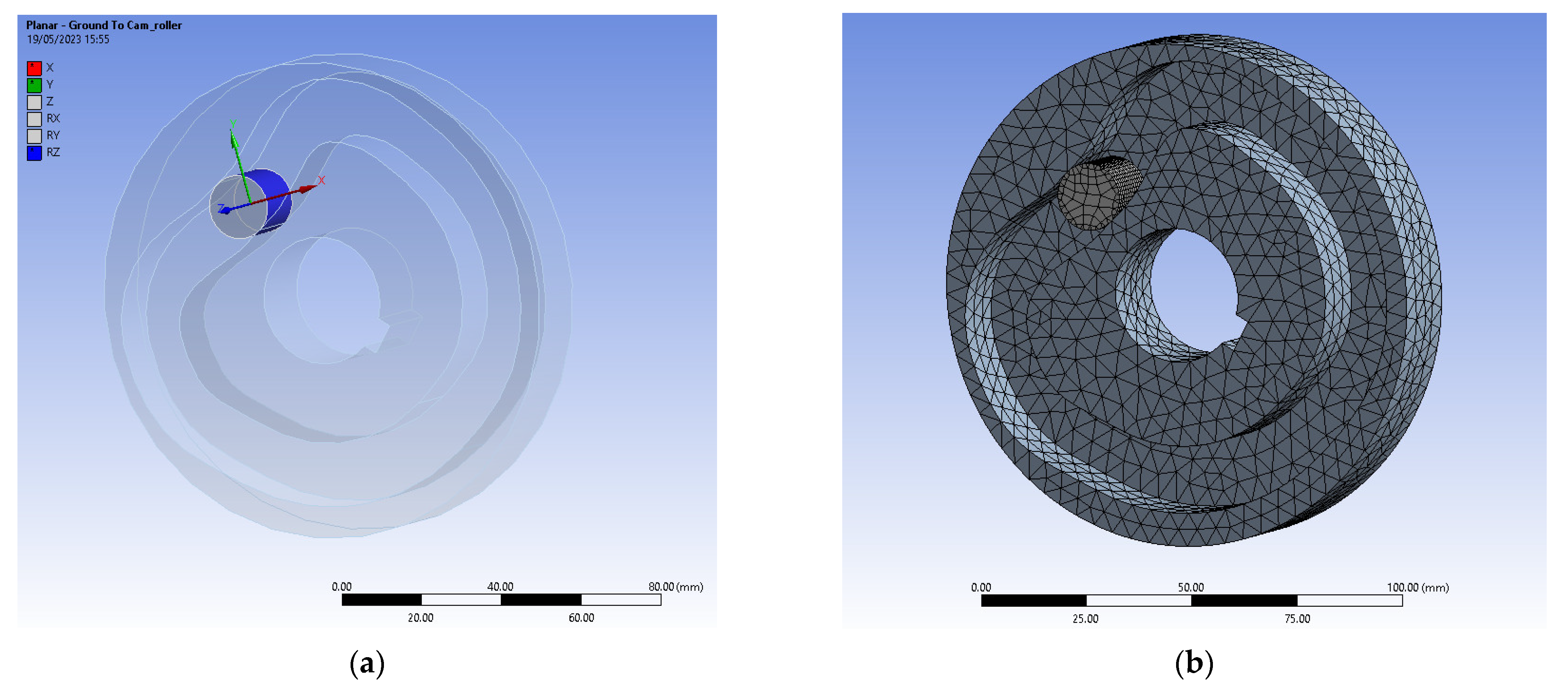
next joint was set to planar and was scoped to the outer surface of the follower roller. This gave the possibility to follow the needed path, as this type of joint allows only translations on
X and
Y and rotations around
Z (see
Figure 4a). Mesh-wise used a body sizing of 5 mm for both components and a face sizing of 1 mm for the surfaces in contact. Error limits were set to aggressive mechanical with a smooth transition between elements. When assessing the rigid body behavior, reducing the dimensions was chosen. That resulted in more than 22,000 nodes and 11,000 elements (see
Figure 4b).
Analyses settings included steps for each point along the path. The large deflection option was turned on, and the un-symmetric option for Newton–Raphson computation was chosen for the nonlinear controls. No stabilization was needed. The other options were left, as the software tool implicitly controlled them. A force was used as the type of load, and three joint loads for the translation on X and Y and the rotation around Z were set.
2.4. Experimental Conditions
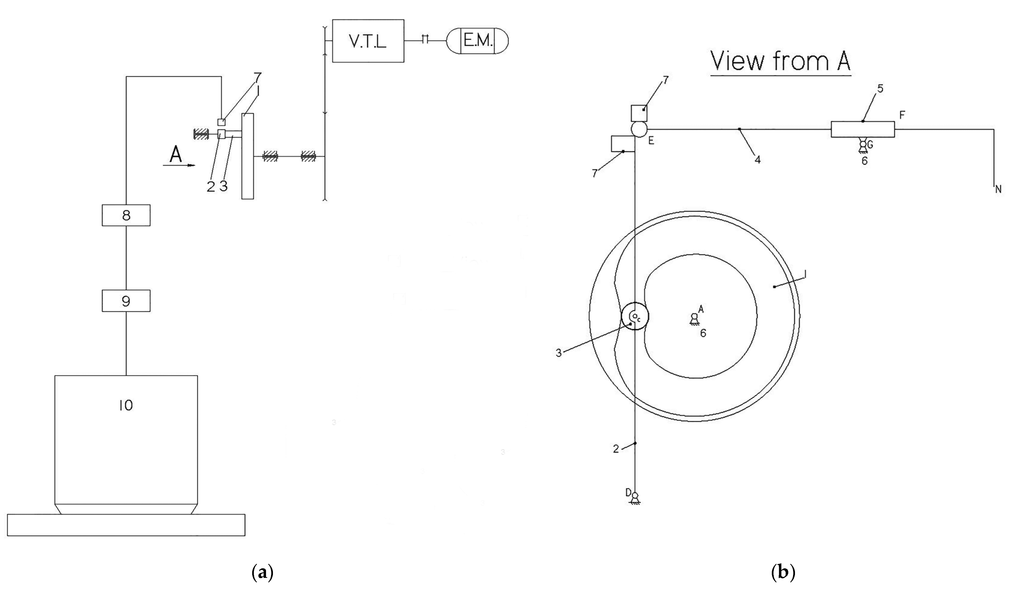
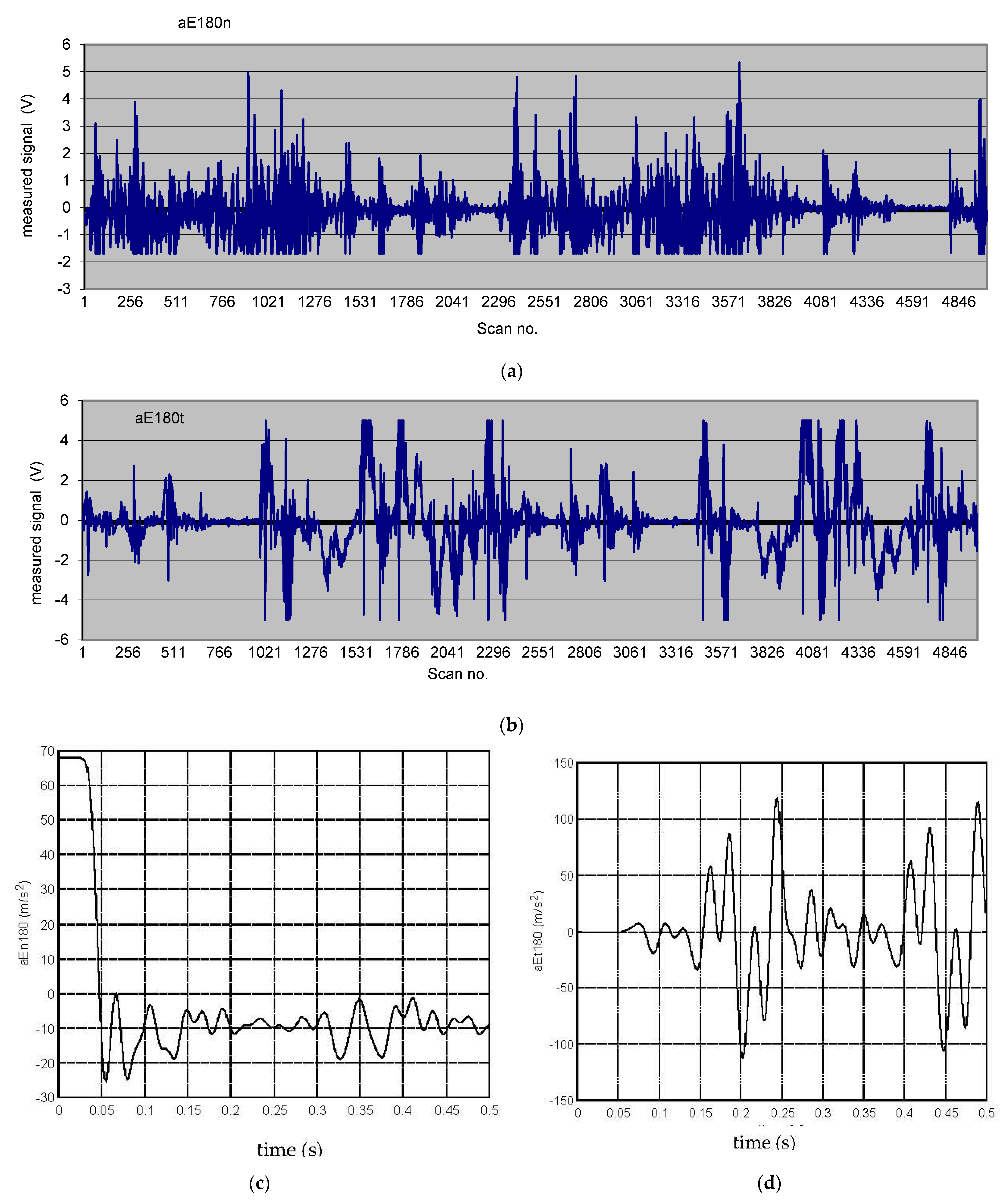
Validation experiments were performed to test the reliable appropriateness of the dynamic model based on elastic cam-follower contact and the simulation data. The structure of the laboratory equipment is schematically shown in
Figure 5, where the symbols represent the following: 1 is the disk cam with a profiled groove, 2 is the oscillating follower, 3 is the follower roller, 4 is a slider (the yarn catcher), 5 is a slide block, 6 is the fixed element (frame), 7 is a PCB model 352A76 accelerometer, 8 is a PCB model 480CO2 amplifier, 9 is a data acquisition board, and 10 is a PC. In the same figure, VTL is a rotation speed variator with a transmission ratio of 1/2 ÷ 2, and EM is a 3-phase asynchronous electric motor with a nominal power of
Pn = 1.1 (kW), a synchronous rotation speed of
nsm = 1000 (rpm), and a nominal rotation speed of
nm = 920 (rpm).
The measurements were performed after the calibration on a system schematically shown in
Figure 6, where the symbols are as follows: 1 is a 6V model I4103 DC power source, 2 is a B&K type 4291 electro-dynamic excitation system, which produced an acceleration of 9.81 m/s at a frequency of 79.6 Hz, 3 is the accelerometer to be calibrated, 4 is a ball device, 5 is the amplifier, 6 is an oscilloscope, 7 is the data acquisition board, and 8 is the PC. A multiplying correction factor
Ka = 86.43 (m/s
2/V) was established for translating the measured electric signals (V) into acceleration values (m/s
2). The tangential and the normal accelerations for the follower, in point E, were measured.
The experimental measurements were performed for a cam with the profile having the law of motion with sine acceleration on the ascending and descending phases. The average value for the backlash in the coupling cam-follower roller was j = 0.128 (mm). The active load was Fu = 0 (N). Measurements were taken for three values of the cam’s rotation speed, at 180, 300, and 500 rpm. The scanning frequency was set to 10,000 scans/s. The measured signal data were processed using a customized virtual instrument developed in the LabVIEW environment.
4. Discussion
Simulation tests on the proposed theoretical dynamic models returned a great amount of data and information regarding the influences of the geometrical parameters and the technological conditions on the investigated indicators of the jump phenomenon in contact loss for the studied cam-follower mechanism.
The numerical simulation results for the dynamic model with rigid elements highlighted more than one follower jump and impact during the rising phase of the follower. The acceleration jumps for the follower at its impact with the cam is theoretically infinite because modeling the impact was considered instantaneous.
Regarding the influences of the input parameters Fu, j, n1, and Jt on the investigated jump phenomenon indicators, the simulation results for the dynamic model with rigid elements showed the following: bigger values for Fu, n1, and Jt determined bigger values for (MR13D)max, bigger values for j and Jt determined bigger values for (φ2rcj-φ2rfj)max, bigger values for Fu determined smaller values for (φ2rcj-φ2rfj)max, bigger values for j, n1, and Jt determined bigger values for (ω2rcj-ω2rfj)max, bigger values for Fu determined smaller values for (ω2rcj-ω2rfj)max, bigger values for n1 and Jt determined bigger values for (ω1rcj-ω1rfj)max, bigger values for Fu determined smaller values for (ω1rcj-ω1rfj)max, bigger values for j, n1, and Jt determined bigger values for (Percussionint)max, bigger values for Fu determined smaller values for (Percussionint)max, bigger values for Fu and n1 determined bigger values for (Jumps no.), and bigger values for j determined smaller values for (Jumps no.).
One could conclude that the increase in Fu values diminishes the negative dynamic effects related to contact loss, as effects of j, n1, and Jt are the opposite. In order to avoid the jump of the follower, it appeared necessary to increase Fu and decrease the speed of the cam and the generalized mass of the follower.
For the law of motion with sine acceleration, the jump occurred at a lower cam speed than for the law of motion with cosine acceleration. That was because the law of motion with sine acceleration had absolute values of acceleration bigger than the law of motion with cosine acceleration [
52].
The numerical simulations for the dynamic model with elastic contact highlighted the following: bigger values for Fu, n1, and Jt resulted in bigger values for (MR13D)max, bigger values for n1 and Jt resulted in bigger values for (xel)max, bigger values for Fu resulted in smaller values for (xel)max, bigger values for n1 and Jt resulted in bigger values for (Jumps no.), and bigger values for Fu resulted in smaller values for (Jumps no.). The input parameter j did not prove a significant effect on any of the investigated jump phenomenon indicators, (MR13D)max, (xel)max, or (Jumps no.), which could be explained by the fact that no impact resulted in the rising phase of the follower.
One could conclude again that for the dynamic model with elastic contact, the increase in Fu values diminished the negative dynamic effects related to contact loss, and the effects of n1 and Jt were the opposite. For the law of motion with sine acceleration, the jump occurred at a lower cam speed than for the law of motion with cosine acceleration, which is again a valid conclusion.
By comparing the simulation results for the two dynamic models, one could observe significant differences regarding the indicator (Jumps no.). The explanation could be found in the fact that at the beginning of the rising phase, a so-named deepening of the follower into the cam’s profile, eventually followed by the contact loss and jump, occurred. The important effect of the cam-follower contact elasticity is, therefore, highlighted.
Related to the FEA results, one could conclude that the graphical distribution of gap occurrences may help in optimizing the CAE model considering various scenarios.
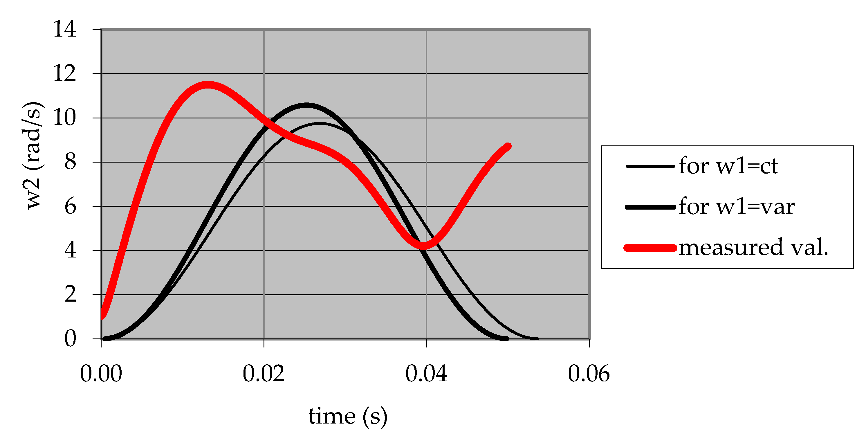
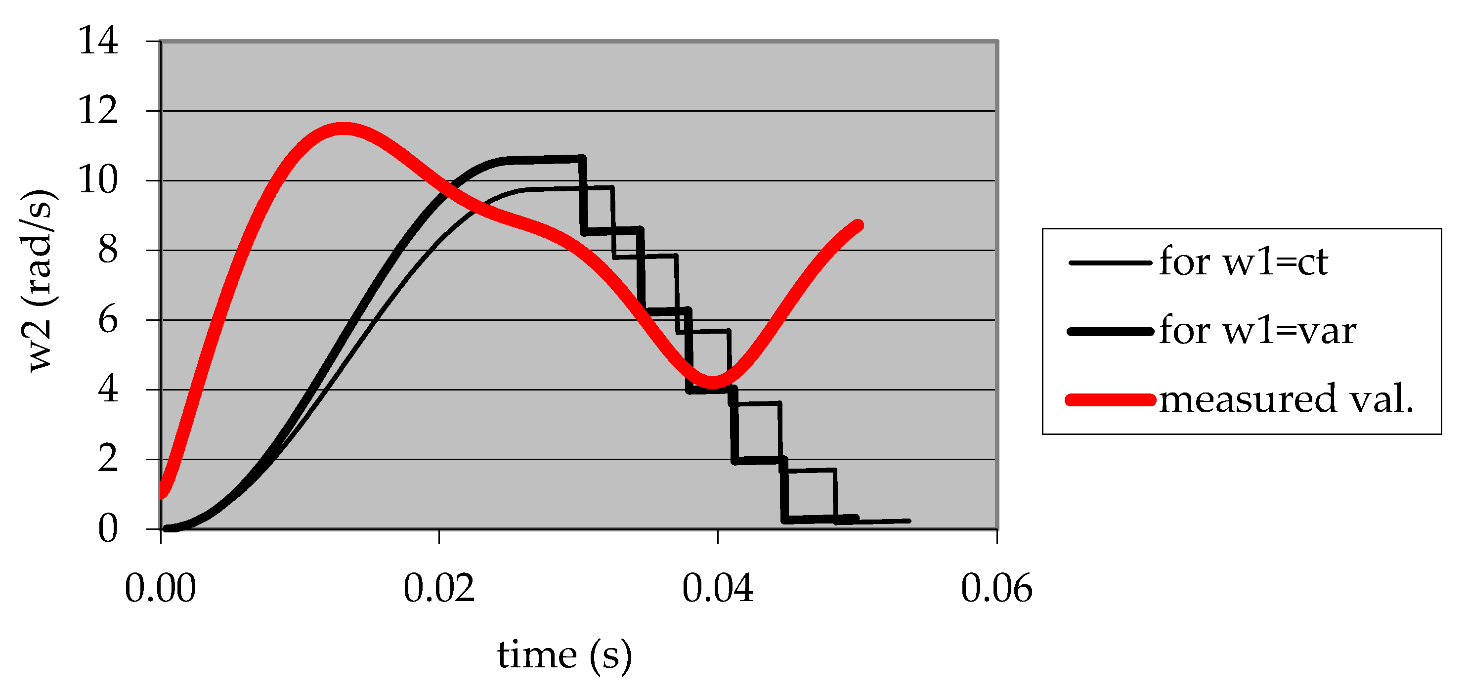
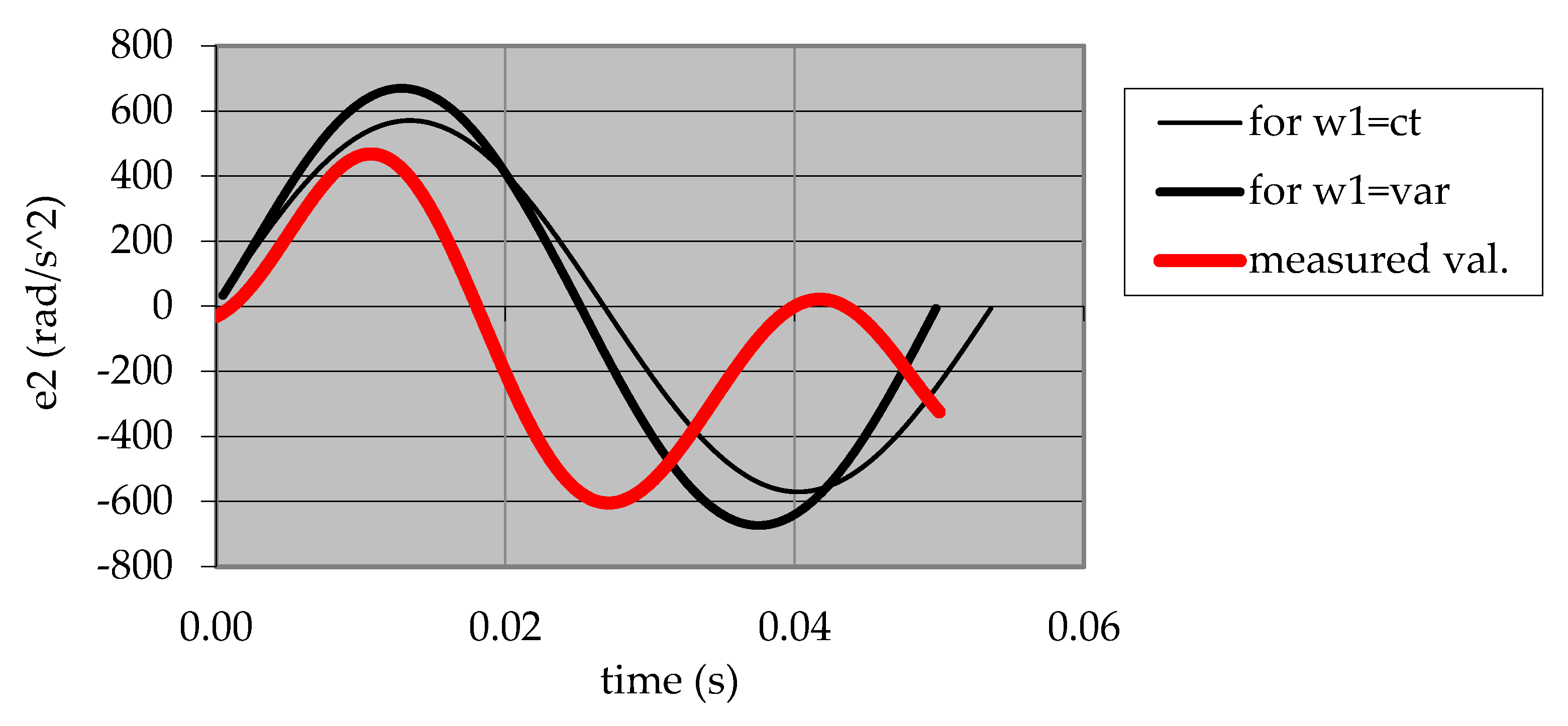
Experimental data highlighted that the dynamic model with elastic contact delivered results closer to the experiment, mainly regarding the number of jumps and impacts.
A comparison of the experimental results for different values of the cam speed led to the conclusion that the negative dynamic effects are bigger for bigger values of the cam speed.
The registered differences between the simulation data and the experimental data resulted from the nature of the simplifying hypotheses assumed in modeling.
5. Conclusions
Within the broad context of cam mechanism dynamics research, the influence of the backlash from the higher kinematic pair cam-follower was less studied, mainly for the situation of the mechanisms with a disk cam with a profiled groove and an oscillating follower. Such a mechanism from an automated feeding system of a textile machine was studied within the presented research approach. Although the customized research details and results were specific to the particular studied mechanism, the approach has general validity and can be extended to other situations in this class of mechanisms.
Theoretical dynamic modeling and simulation of the complex phenomena in cam mechanism dynamics may deliver important reliable information that is useful for predicting the quality and efficiency in real process operation. The idea to develop two dynamic models, one considering rigid elements in contact and the second considering elastic cam-follower contact, highlights the influence of the cam-follower contact elasticity on the jump phenomenon.
Hypotheses of theoretical dynamic modeling excluding the influence of factors, such as friction in kinematic couplings, the masses and the inertia moments of the kinematic elements of the driving chain from the electrical motor up to the camshaft, the rotational kinetic energy for the follower roller, and the elasticity of the other elements of the mechanism, resulted in limitations of the theoretical models in accurately predicting the specific dynamic behavior.
The models were tested within a simulated experiment, and numerical simulation results evidenced the influence of input factors like the applied load on the mechanism, the backlash in the higher kinematic pair cam-follower, the rotational speed of the cam, the inertia moment reduced to the follower, and some indicators of the jump phenomenon.
The importance of theoretical modeling and simulation is given by the unlimited number of input conditions that can be simulated, as presented above in
Section 2.2 and
Section 3.1, for obtaining valuable referential data in experiment planning or real operation behavior predicting.
The FEA research approach delivered important results that were helpful in the virtual testing of the dynamic models. However, it is recommended that the FEA-obtained results may be used with care since it was acknowledged that further refinement is necessary in terms of mesh quality and setup conditions.
Validation experiments were performed, proving the reliable appropriateness of the dynamic model based on the elastic cam-follower contact. Experimental values for the investigated dynamic parameters confirmed the research hypotheses and expectations.
In the future, a more in-depth theoretical approach for developing a more relevant dynamic modeling algorithm and extended FEA approaches will concern the authors. These will be intended to reduce the simplifying hypotheses and consider other influence factors such as friction, thermal phenomena, material elasticity, etc.
