Abstract
Due to their advantages of compact size, high reduction ratio, large stiffness and high load capacity, RV reducers have been widely used in industrial robots. The dynamic characteristics of RV reducers in terms of vibratory response and dynamic transmission error have a significant influence on positioning accuracy and service life. However, the current dynamic studies on RV reducers are not extensive and require deeper study. To bridge this gap, a more effective and realistic lumped parameter dynamic model for RV reducers is developed, considering the tooth profile modification of cycloid gears and system errors. Firstly, for an efficient solution, the equivalent pressure angle and equivalent mesh stiffness of the cycloid–pin gear pair are introduced in the dynamic model based on the loaded tooth contact analysis. Secondly, the differential equations of the system are derived by analyzing the relative displacement relationships between each component, which are solved using the Runge–Kutta method. With this, the effects of errors such as machining errors, assembly errors and bearing clearances on the dynamic behaviors and transmission precision are investigated by comparison to quantify or qualify their influence. This research is helpful in characterizing the multi-tooth mesh and dynamic behavior, and revealing the underlying physics of the RV reducer.
1. Introduction
The rotary vector (RV) reducer has already been generally introduced in diverse engineering fields, especially in industrial robot joints, making up 39% of the whole cost among all the components of an industrial robot [1]. The RV reducer mechanism is chiefly composed of a two-stage transmission mechanism, where an involute planet gear drive is the first reduction and a cycloid–pin gear drive is the second reduction. Due to their delicately designed structure, RV reducers have many advantages compared to other types of reducers, including their compact size, small backlash, high reduction ratio, large stiffness and high load capacity [2,3].
Recently, the analysis of the multi-tooth meshing characteristics and dynamic behaviors of RV reducers has become a very active topic of research. Huang et al. [4] proposed a meshing stiffness analysis model of the BRV (beveloid rotate vector transmission) for better understanding the dynamic characteristics of BRV transmission systems. Li et al. [5] proposed an effective loaded analysis model based on the minimum energy principle for the RV reducers to predict the load distribution and contact conditions. Jang et al. [6] proposed a new modified cycloid reducer with an epitrochoid tooth profile and established a theoretical model for force and efficiency analyses. Jin et al. [7] conducted a multi-body dynamics simulation using virtual prototyping technology to investigate the influence of design factors on the dynamic transmission precision. Wang et al. [8] proposed multi-tooth contact and transmission error models by dividing the contact area of tooth pairs into several differential elements. Wang et al. [9] established the torsional vibration equations of the RV reducer with the trigonometric function-fitting torsional stiffness obtained by the torsional stiffness test, and simulated the torsional vibration response of the RV reducer based on the Runge–Kutta method. Xu et al. [10] developed a contact dynamic model of cycloid drives to analyze the load distribution with consideration of the cylindrical roller-bearing effects. Wu et al. [11] analyzed the transmission error of the RV reducer with manufacturing and assembly tolerances, and investigated the sensitivities of the kinematic error with respect to various design parameters based on the Monte Carlo method. Li et al. [12] established a new theoretical contact analysis model of cycloidal–pin gear transmission, considering the tooth profile and pitch errors of the cycloidal gear. Li et al. [13] proposed an analytical method to calculate the contact stress and stiffness, transmission error and gear ratio of a cycloid speed reducer, considering the effects of tooth profile modifications and eccentric error. Li et al. [14] proposed a new tooth profile modification method involving the cycloid gears of RV reducers for robots by establishing the relationship between the modifications and the pressure angle distribution. Huang et al. [15] proposed a computerized approach of loaded tooth contact analysis based on the influence coefficient method, either for the contact tooth pairs of the involute stage or of the cycloid stage of the RV reducer. Hsieh et al. [16] investigated four differently structured two-stage cycloid speed reducers by analyzing the component motion and stress conditions during reducer operation. Yang et al. [17] developed a dynamic model by considering the influence of bearing stiffness, crankshaft bending stiffness and mesh stiffness; the governing equation of motion was derived and solved by using the Fourier series method. Hao et al. [18] proposed the rigid–flexible coupling dynamic simulation method of planetary gear transmission based on Multi-Flexible-Body Dynamics (MFBD) technology, which was used to obtain the dynamic stress distribution of planetary gear and to investigate the dynamic response characteristics. Hsieh et al. [19] investigated the contact and collision conditions and stress variations during transmission by constructing a system dynamics analysis model of a cycloidal speed reducer. Huang et al. [20] conducted a dynamic characteristics analysis on an internal mesh planetary gear with small tooth number difference (PGSTD) reducer by means of the dynamic contact FE method. Wei et al. [21] proposed a dynamic modeling method for the coupling vibration analysis of the planetary gear system by applying a virtual equivalent shaft element in order to overcome the lack of fidelity of the lumped parameter models and the high computational cost of finite element models. Wang et al. [22] developed a novel general system–structure coupling dynamic analysis procedure to analyze the dynamic performance of planetary gears. The dynamic loads of gears were taken as excitations for the structural dynamic analysis. Chen et al. [23] proposed a dynamic model for planetary gearboxes considering the clearance of the planet gear, sun gear and carrier bearings, as well as sun gear tooth crack levels. Zhang et al. [24] proposed a non-random vibration analysis method for RV reducers based on the deterministic vibration model to analyze the vibration of its core components. Matejić et al. [25] provided efficiency analysis for a new two-stage cycloid drive concept based on losses generated by friction, and drew comparisons with the current schemes in practice. Bednarczyk et al. [26] found that the forces, contact pressures and backlash distribution were strongly determined by the tolerance of the radius of the bushings’ arrangement and holes in the planet wheel by analyzing the cycloidal reducer output mechanism, considering machining deviations. Blagojević et al. [27] designed a new concept on a two-stage cycloidal speed reducer, in which only one cycloid disc was used per stage to enhance the structure compactness, and conducted a simulation to confirm its dynamic balance and stability. Gorla et al. [28] proposed the structure and motion principles of a novel cycloidal speed reducer and designed a simplified procedure to calculate the force distribution on cycloid drive elements, its power losses and its theoretical mechanical efficiency. Efremenkov et al. [29] projected an algorithm for automatically calculating the force and stress of a cycloid reducer with the advantage of rapidity and high accuracy to achieve the best initialization of parameters, so as to minimize the force impact on the mechanism parts. Maccioni et al. [30] proposed a new three-stage gearbox architecture, called Nested, to obtain high reduction ratios and maintain its relatively compact overall dimensions.
The literature review shows that many research works have focused on the load distribution and dynamic analyses of cycloid-type drives and planetary gear drives, respectively. The contact strength and vibratory response are thought to have a significant influence on the transmission accuracy and service life of gear drives. However, for the RV reducer, as a combination of the above, the current dynamic studies are not extensive and need to be deeper compared with those of the involute gearings. Therefore, to characterize the multi-tooth mesh and dynamic behavior, and reveal the underlying physics of the RV reducer, a more effective and realistic lumped parameter dynamic model for RV reducers is developed, considering the tooth profile modification of cycloid gears and system errors.
2. Quasi-Static Analysis of Cycloid–Pin Gear Pairs
2.1. Tooth Contact Analysis of Cycloid–Pin Gear Pairs
Tooth contact analysis (TCA) is a powerful tool for determining the time-varying meshing information of the gear pair. The TCA of cycloid–pin gear pairs is introduced directly as the basis for the following dynamic modeling. As shown in Figure 1, two moveable coordinate frames and are rigidly connected with the pin gear and the cycloid gear, respectively. A stationary coordinate system has its origin coinciding with that of .
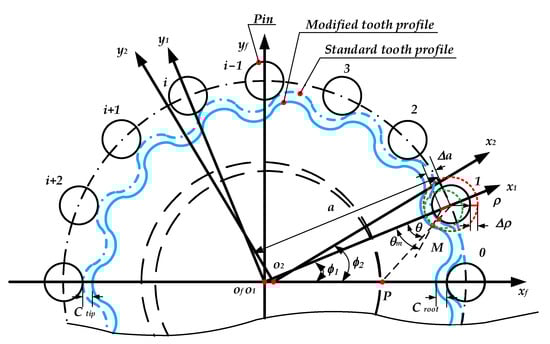
Figure 1.
Coordinate system of cycloid gear with modification.
According to the gearing meshing theory, the position vector and normal vector of cycloid-pin gear pairs at any meshing point must comply with two meshing conditions, which are the coincidence of the position vectors and the collinearity of the normal vectors. Thus, the corresponding equation is expressed as follows:
where and are the position vector and normal vector of the pin gear in after matrix transformation. Similarly, and are the position vector and normal vector of the cycloid gear in after matrix transformation.
As a consequence, two vector equations, with four unknown parameters and a given value of , can be derived as nonlinear equations. Because of the unit normal vector, the equation can be determined at any time, such that the above two vector equations can be solved by three unknown parameters. With this, the meshing information can be determined to calculate the equivalent mesh stiffness and pressure angle of the cycloid–pin gear pair in the loaded TCA, including the contact point, backlash and transmission error.
2.2. Loaded Tooth Contact Analysis of Cycloid–Pin Gear Pairs
2.2.1. Hertzian Contact Stiffness
The meshing stiffness of the single cycloid–pin gear pair should be determined to establish the relationship between the loads and corresponding deformation. In this paper, only the contact deformation is mainly considered in the meshing stiffness based on the Hertzian contact theory, which provides much more influence than bending and shear deformations on tooth deflections. The contact model of a single cycloid–pin gear pair is illustrated in Figure 2. Since the size of the elastic deformation is tiny compared with the radial dimension of the pin and cycloid gear tooth, the curvature radius of the contact zone can be regarded as unchanged. Thus, the Hertzian contact stiffness is expressed as
where the subscripts and represent the pin and cycloid gear. Symbols and are Poisson’s ratio and the elasticity modulus, and and are the equivalent elasticity modulus and radius of curvature, respectively. Symbols and are the width of the contact zone and of the cycloid gear, respectively. Therefore, the Hertzian contact stiffness is a nonlinear expression concerning geometrical parameters, material properties and applied load.
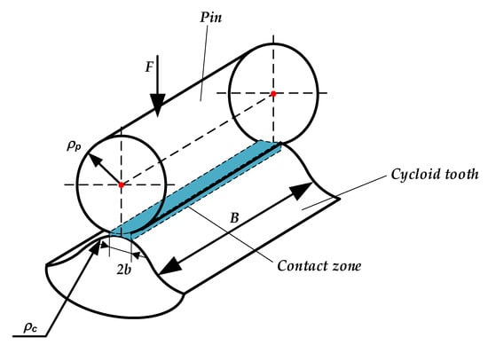
Figure 2.
Hertzian contact stiffness model.
2.2.2. Compatibility and Equilibrium Conditions
Referring to the related literature [31], the compatibility condition can be presented as
where is the elastic rotational angle, is a micro-angular displacement of its corresponding tooth and is the backlash of the corresponding cycloid–pin gear pair.
Assuming the effect of each contact point as a tiny spring with time-varying Hertzian contact stiffness along the action line, the detailed load distribution model is shown in Figure 3. The number of tooth pairs in contact equals that of the springs. Then, the external torque applied on the cycloid gear should equal the moment generated by the loads of pins acting on the cycloid gear to establish moment equilibrium equations:
where is the contact force of the th cycloid–pin gear pair, is the external torque and is the elastic deformation of the th cycloid–pin gear pair along the action line. Because the deformation angle is tiny, the formula can be approximately derived.
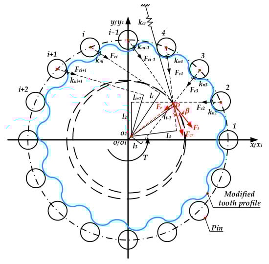
Figure 3.
Load distribution model of the cycloid–pin gear pair.
2.3. Equivalent Pressure Angle and Mesh Stiffness
As shown in Figure 3, each contact force of the cycloid–pin gear pair converges at the pitch point along their own line of action. The resultant force at the pitch point can be decomposed as the resultant tangential force and the resultant radial force , which can be expressed as
where is the pitch radius of the cycloid gear.
Then, the total resultant force can be derived by
Then, the equivalent pressure angle and equivalent mesh stiffness can be represented as follows:
where is the tooth number of the cycloid gear and the is the elastic rotation angle. By using the two parameters, the multi-tooth contact condition of the cycloid–pin gear pair can be made equivalent to a single tooth contact gear pair to reduce the number of degrees of freedom and then to improve the solution speed of the dynamic model.
3. Dynamic Model of RV Reducer
3.1. Basic Assumptions and Coordinate Systems
To simplify the dynamic model of the RV reducer, several assumptions are given, as follows:
- (1)
- The whole structural distortion of the gears and output disc is negligible.
- (2)
- Each component vibrates in the plane normal to its axis.
- (3)
- The system is simplified as a lumped parameter model with gears and supports simplified as springs.
- (4)
- Each involute planetary gear with the same material properties and design parameters is distributed along the circumference.
- (5)
- The lubrication condition is negligible to avoid uncertainness and complexity.
The dynamic model of the whole RV reducer based on the lumped parameter method is shown in Figure 4. The general form of RV reducers consists of planet gears and crankshafts with the number of , and cycloid gears with the number of . Considering the mesh stiffness of gear pairs, crankshaft bending stiffness, bearing stiffness and other factors, a translation–torsion coupled dynamic model of RV reducers is established in this section. Each component possesses three degrees of freedom; therefore, there are degrees of freedom of the proposed dynamic model in total.
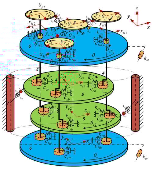
Figure 4.
Three-dimensional dynamic model of the whole RV reducer.
As shown in Figure 5, five movable Cartesian coordinate systems are fixed to the sun gear, planetary gear, crankshafts, cycloid gears and output disc, respectively, which are given by , uniformly revolving around the output disc at its theoretical angular velocity, and is a fixed coordinate system. and indicate the translational displacement of the component, is the angular displacement, and and are the circumferential position of the planet gear and the cycloid gear, respectively.
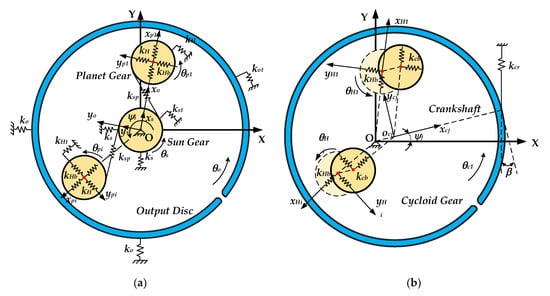
Figure 5.
Coordinate systems of the dynamic model of the RV reducer in (a) the high-speed stage and (b) the low-speed stage.
In the dynamic model, the symbols and stand for the radial supporting stiffness of the sun gear and output disc, and and stand for the torsional stiffness of the sun gear and output disc, respectively. is the mesh stiffness between the sun and planet gear. and represent the bending stiffness and torsional stiffness of the crank shaft. and represent the stiffness between the supporting bearings and turning arm. is the equivalent mesh stiffness of the cycloid–pin gear pair.
3.2. Mesh Stiffness Excitation and System Error Analysis
The system dynamic excitation includes inner excitation and external excitation. The inner excitations of RV reducers, including gear mesh stiffness excitation and transmission error excitation are mainly investigated in this section.
3.2.1. Mesh Stiffness Excitation
The plots of two kinds of mesh stiffness for the involute gear pairs and cycloid–pin gear pairs vary with the change in mesh position, with the same curve shape. Therefore, the phase angle is used to express the mesh stiffness at different meshing positions. The phase angle is defined as the phase difference in the mesh stiffness of the planet gear, which is expressed as
where is the number of sun gear teeth.
Assuming the mesh stiffness of the involute gear pairs varies with the rule of the rectangle wave, it can be expanded into a Fourier series:
where is the average mesh stiffness, is the involute gear meshing frequency, is the order of harmonic waves, , , and are the amplitude of the harmonic wave with order and is the initial phase angle.
Similarly, the phase angle is defined as the phase difference in the mesh stiffness of the cycloid gear, which is expressed as
where is the pin tooth number.
According to the calculation method of the mesh stiffness of cycloid–pin gear pairs mentioned above, it can be derived and expanded into a Fourier series form:
where is the average value of mesh stiffness, is the meshing frequency of the cycloid-pin gear pair, and are the amplitude of the harmonic wave with order , is the phase angle of and and is the initial phase angle.
3.2.2. System Error Analysis
- (1)
- Equivalent error between the sun and planet gear at the mesh and support positions.
The equivalent error generated by the machining error between the sun and planet gears along the mesh line is shown in Figure 6, where two circles represent the base circles. The eccentric machining error of the sun and planet gears is expressed as and . Then, the equivalent error and along the mesh line is represented as follows:
where , is the angular velocity of the output disc, is the reduction ratio of the whole reducer system, is the mesh angle of the sun and planet gear and , and are the rotation angle of the sun gear, planet gear and output disc, respectively. is the initial phase angle of the planet gear.
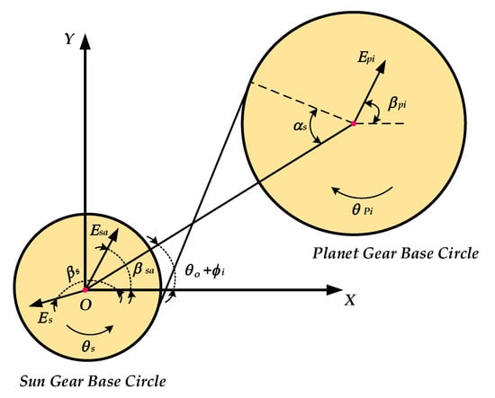
Figure 6.
Equivalent error between the sun and planet gears.
Assuming the eccentric assembly error of the sun gear as , the generated equivalent error along the mesh line can be written as follows:
Then, it can be decomposed to the X-axis and Y-axis, where the equivalent errors and can be yielded as follows:
- (2)
- Equivalent error of the cycloid-pin gear drive at the mesh and support positions.
The equivalent error of the cycloid–pin gear drive is mainly derived from two parts: the connection between the crankshaft cam and a cycloid gear hole through the turn-arm bearing, and the meshing between the cycloid gears and pins.
The eccentric error of the cycloid gear hole is , as shown in Figure 7, and its components and in the X-axis and Y-axis can be yielded as follows:
where , since the self-rotation velocity of the cycloid gear is equal to the rotation velocity of the output disc.
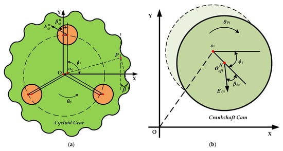
Figure 7.
Equivalent error (a) in the crankshaft holes of the cycloid gear and (b) in the crankshaft cam.
The eccentric error of the crankshaft cam is , and its components and in the X-axis and Y-axis can be yielded as follows:
where is the initial phase angle of the cycloid gear.
Then, the bearing clearance of the crankshaft bearing is , and the generated equivalent error at the contact point is expressed as
The equivalent error of the cycloid–pin gear pair along the mesh line is represented as follows:
where, is the total composite error along the mesh line.
- (3)
- Equivalent error of the output disc at the contact or support position.
As is presented in Figure 8, the eccentric error of the hole in the output disc is , and its components and in the X-axis and Y-axis can be yielded as follows:
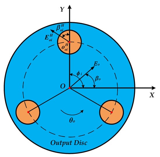
Figure 8.
Equivalent error between the output disc and crankshaft holes.
The bearing clearance of the support bearing between the hole in the output disc and the corresponding crankshaft is , and the generated equivalent error at the support point is expressed as
Assuming the assembly error of the output disc is , its equivalent errors in the X-axis and Y-axis, and , can be yielded as follows:
The bearing clearance of the support bearing between the output disc and pinwheel is , and the generated equivalent error at the support point is expressed as
3.3. Formulations of Motion Equations
3.3.1. Relative Displacements
The acting forces between two movable components in RV reducers are in direct proportion to the relative displacements of the corresponding components. To establish the motion equations, the relationships in terms of the relative displacement of all the interactional movable components are determined.
- (1)
- Relative displacement projection of the sun and planet gears along the mesh line.
The relative displacement is obtained:
where , is the engagement angle of the sun and planet gears, and and are the base circle radius of the sun and planet gears, respectively.
The relative displacements of the sun gear at the support position decomposed to the X-axis and Y-axis, and , can be yielded as follows:
- (2)
- Relative displacement projection of the crankshaft and cycloid gear along the translational direction of the crankshaft.
The relative displacement between two components can be derived as follows:
where and is the initial phase angle of the crankshaft.
- (3)
- Relative displacement projection of the crankshaft and the output disc along the translational direction of the crankshaft.
The relative displacement between two components can be derived as follows:
where and is the initial phase angle of the crankshaft.
The relative displacement of the output disc at the support position decomposed to the X-axis and Y-axis, and , can be yielded as follows:
- (4)
- Relative displacement projection of the cycloid gear and pins along the mesh line.
The relative position relationship of the components can be derived:
where is the equilibrium pressure angle of the cycloid–pin gear pairs.
3.3.2. Motion Equations
Based on Newton’s second law and the theorem moment of the momentum of the relative mass center, motion equations of each component can be derived.
The motion equations of the sun gear are expressed as follows:
The motion equations of the planet gear are expressed as follows:
The motion equations of the crankshaft are expressed as follows:
The motion equations of the cycloid gear are expressed as follows:
The motion equations of the output disc are expressed as follows:
The input torque and load are and . The mass of the sun gear, planet gear, crankshaft, cycloid gear and output disc is , , , and , respectively. The corresponding rotational inertial is , , , and , respectively.
Then, the motion equations of RV reducers in the matrix form can be derived as
where is the generalized coordinate vector.
The excitation force vector results from the centripetal acceleration of the planetary component.
, and stand for the generalized mass matrix, gyroscope matrix and excitation force vector, respectively. is the damping matrix, and and represent the support bearing stiffness matrix, mesh stiffness matrix and centripetal matrix.
4. Analysis Results and Discussion
The solutions for the differential equations are obtained with numerical integration methods. The standard integration procedure ode45 in MATLAB is used in this investigation to verify the correctness of the proposed dynamic model of RV reducers. The main geometrical parameters of an experimental RV reducer are listed in Table 1. The material properties of the gear pairs are presumed to be the same, with a Poisson’s ratio of = 0.3 and Young’s modulus of 206 GPa. The output torque is 450 N∙m, and the input rotation speed is 1500 r/min. The dynamic parameters are listed in Table 2.

Table 1.
The main geometrical parameters of the experimental RV reducer.
Table 2.
Dynamic parameters used in the experimental RV reducer.
4.1. Numerical Solution of Equivalent Pressure Angle and Mesh Stiffness
Based on the unloaded and loaded TCA mentioned in Section 2, the equivalent pressure angle and mesh stiffness of the cycloid–pin gear pair are calculated, which are time-varying and load-dependent. By using the above geometrical parameters of the experimental RV reducer, the effects of the tooth profile modification of the cycloid gear are investigated by comparing the two cases with and without modification. For the case with tooth profile modification, the roller position and the roller radius modification amounts are −0.05 mm and −0.01 mm, respectively. Then, the mean values of equivalent pressure angle and mesh stiffness are fed into the proposed dynamic model of the RV reducer for subsequent dynamic response analysis.
Figure 9 presents the plots of the equivalent pressure angle and mesh stiffness of the cycloid–pin gear pair with and without tooth profile modification. It is clearly seen that both the equivalent pressure angle and mesh stiffness for the two cases vary periodically as the crankshaft rotates. For the case without modification, the equivalent pressure angle varies from about 31.5° to 32.1° with a mean value of 31.9°. The equivalent mesh stiffness shows a sinusoidal shape curve and a mean value of N/m. It is well known that the tooth profile modification of cycloid gears is able to compensate for machining errors, to accomplish easy disassembly and assembly and to provide good lubrication conditions. When the tooth profile modification is applied, a large disparity is observed, in that the mean values of both decrease to 3.8° and N/m, and both their amplitudes increase, with more abrupt changes in a periodic cycle. According to the above contrastive analysis, this indicates that the tooth profile modifications have a significant effect on the equivalent pressure angle and mesh stiffness of the cycloid–pin gear pair, which should be adequately considered in the dynamic model of the RV reducers.
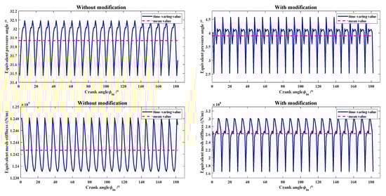
Figure 9.
Influences of modification on the equivalent pressure angle and mesh stiffness.
4.2. Dynamic Responses in the Time Domain
Based on the proposed dynamic model of the RV reducer, the analysis of dynamic responses in the time domain is given, considering the system errors based on the previous data of prototype manufacturing and measuring, as presented in Table 3. The tolerance levels are chosen from IT5 to IT6 based on the ISO tolerance system.
Table 3.
Various errors of the main components.
Figure 10a–d show the dynamic responses of the sun gear, planet gear, cycloid gear and output disc for two cases with or without errors. For all four figures, the upper-left subfigures describe the trajectories of the components. It can be observed that the trajectories appear to be a series of complicated and closed curves, which make it hard to judge the motion states based only on the perspective of the motion trajectory. Moreover, the motion space without errors is much smaller than that in cases with errors, which implies that the vibration displacements of the components are sensitive to system errors.
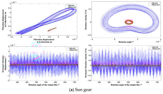
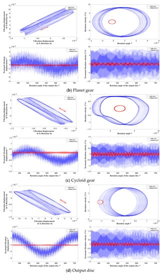
Figure 10.
Dynamic response curves of components of the RV reducer.
The upper-right subfigures of all four figures illustrate the phase diagrams of rotation angle and rotation velocity. The phase trajectories repeat themselves every period with a difference in translational transformation, and then form a series of curve families. For the cases without errors, the phase trajectories manifestly take up much less space, undergo less translational transformation and much more closely approach a perfect circle than those with errors. According to the relevant vibration theories with phase plane analysis in mechanical engineering, since the phase diagrams of both the error and no-error cases are closed, quasi-regular curves, the motion systems of both are under the quasi-period state. It can also be observed from the phase diagrams that the motion state of components with errors is relatively much more complicated and chaotic than those without errors, and further shows the nonlinear characteristic of the motion system.
The two subfigures at the bottom position of all four figures show the torsional vibration angle and velocity, with the rotation of the output disc. Combined with the above phase plane diagrams, it can be deduced that when the phase trajectories overlap themselves relatively completely, the time domain diagram is a sine curve only with small period variation and without large period variation, while if the phase trajectories do not overlap, the time domain diagram is a sine curve with both small period variation and large period variation. When the phase trajectories do not vary smoothly, there is an abrupt change in the time domain diagrams. The larger the size of the phase trajectories, the wider the variation range of the time domain diagrams. As a result, the dynamic responses show that the transmission system is in state of periodic motion and much useful information can be derived from the phase plane diagrams.
4.3. Effects of System Errors on the Dynamic Transmission Error
As shown in Figure 11a,b, for the case without errors, the system dynamic transmission error varies with a small periodic cycle, and its peak-to-peak value is only , as expected under ideal conditions, which also verifies the correctness of the proposed dynamic model of RV reducers. For the case with system errors, it varies periodically as the output rotates, with an increasing peak-to-peak value of . Therefore, it can be easily found that the system errors have a large impact on the transmission precision of the RV reducer. Figure 11a,b also illustrate the differences between a system with error and a system without error in the frequency domain. It is clearly found that the system transmission error increases and occur in more frequency ratio positions with the appearance of errors, which can explain why both the transmission system error increases and the variation rule changes in the time domain. To validate the predicted results of the proposed model, the system transmission errors of a manufacturing prototype with almost the same errors and tooth profile modifications are tested with the self-developed test platform, as shown in Figure 12a,b. It can be observed that, in the forward and reverse rotation, the peak-to-peak values are and with cyclical fluctuations, and are close to those predicted by the proposed model, which shows the effectiveness of the precision prediction by the proposed model.
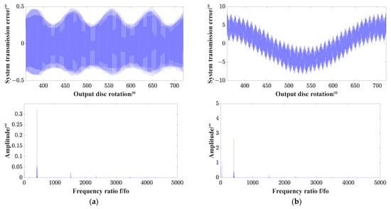
Figure 11.
System transmission error and spectrum analysis: (a) without error; (b) with error.
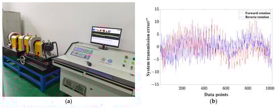
Figure 12.
System transmission error test of the prototype: (a) the test platform; (b) plots of the system transmission errors.
5. Conclusions
In this paper, a dynamic model of RV reducers based on the lumped parameter method is proposed based on some assumptions and simplifications by ignoring the lubrication effect and the structural distortion of the gears and output disc, and by considering each gear pair with the same material properties and design parameters. The model can used to investigate the influences of errors such as machining errors, assembly errors and bearing clearances on the dynamic responses and system transmission precision of RV reducers. With the proposed model, a detailed parametric study using error sensitivity analysis can be conducted in the future, which is of great meaning for the total design and optimization process of the RV reducer. According to the above analysis results, some conclusions can be drawn, as follows:
- Through quasi-static analysis based on the LTCA, the tooth profile modifications have a significant effect on the values of the equivalent pressure angle and mesh stiffness of the cycloid–pin gear pair, which should be adequately considered in the dynamic model of the RV reducers.
- The motion trajectories and phase plane diagrams are vulnerable to influence from the system errors of the components. From the phase plane diagrams, it can be seen whether the system motion state is under the quasi-static or chaotic state, and many kinds of variation characteristics of the time domain diagrams are disclosed.
- The system errors of the components significantly affect the dynamic transmission error magnitude and variation rule, illustrating that error is truly an important factor related to transmission precision.
Author Contributions
X.L., writing, conceptualization, validation, investigation; J.H., writing—original draft preparation; R.G., review and editing; C.D., writing and supervision; W.N., project administration. All authors have read and agreed to the published version of the manuscript.
Funding
This work was supported by the National Natural Science Foundation of China (Grant No. 52005354), and the National Natural Science Foundation of China (Grant No. 52205119) and the Natural Science Foundation of Jiangsu Province (Grant No. BK20220497).
Data Availability Statement
Not applicable.
Acknowledgments
The authors would like to acknowledge the support of the Soochow University, for paying the Article Processing Charges (APC) of this publication. Additionally, the authors wish to acknowledge the editors and anonymous reviewers for their penetrating and wise suggestions to improve the quality of this publication.
Conflicts of Interest
The authors declare no conflict of interest.
References
- Li, T.X.; Zhou, J.X.; Deng, X.Z.; Li, J.B.; Xing, C.R.; Su, J.X.; Wang, H.L. A manufacturing error measurement methodology for a rotary vector reducer cycloidal gear based on a gear measuring center. Meas. Sci. Technol. 2018, 29, 075006. [Google Scholar] [CrossRef]
- Chen, B.K.; Zhong, H.; Liu, J.Y.; Li, C.Y.; Fang, T.T. Generation and investigation of a new cycloid drive with double contact. Mech. Mach. Theory 2012, 49, 270–283. [Google Scholar] [CrossRef]
- Li, S.T. Design and strength analysis methods of the trochoidal gear reducers. Mech. Mach. Theory 2014, 81, 140–154. [Google Scholar] [CrossRef]
- Huang, Y.C.; Du, X.S.; Zhu, C.C.; Ni, G.X.; Ullah, N.; Liu, H. Mesh stiffness analysis of beveloid gears for the rotating vector transmission. Mech. Sci. Technol. 2019, 33, 3943–3953. [Google Scholar] [CrossRef]
- Li, T.X.; Xu, H.; Tian, M. A loaded analysis method for RV cycloidal-pin transmission based on the minimum energy principle. Strojniski Vestn.-J. Mech. Eng. 2020, 66, 655–667. [Google Scholar] [CrossRef]
- Jang, D.J.; Kim, Y.C.; Hong, E.P.; Kim, G.S. Geometry design and dynamic analysis of a modified cycloid reducer with epitrochoid tooth profile. Mech. Mach. Theory 2021, 164, 17. [Google Scholar] [CrossRef]
- Jin, S.-S.; Tong, X.-T.; Wang, Y.-L. Influencing factors on rotate vector reducer dynamic transmission error. Int. J. Autom. Technol. 2019, 13, 545–556. [Google Scholar] [CrossRef]
- Wang, H.; Shi, Z.Y.; Yu, B.; Xu, H. Transmission performance analysis of RV reducers influenced by profile modification and load. Appl. Sci. 2019, 9, 4099. [Google Scholar] [CrossRef]
- Wang, S.; Tan, J.; Gu, J.J.; Huang, D.S. Study on torsional vibration of RV reducer based on time-varying stiffness. Vib. Eng. Technol. 2021, 9, 73–84. [Google Scholar] [CrossRef]
- Xu, L.X.; Chen, B.K.; Li, C.Y. Dynamic modelling and contact analysis of bearing-cycloid-pinwheel transmission mechanisms used in joint rotate vector reducers. Mech. Mach. Theory 2019, 137, 432–458. [Google Scholar] [CrossRef]
- Wu, K.Y.; Shih, Y.P.; Lee, J.J. Kinematic error analysis of the rotor vector gear reducer with machining tolerances. Braz. Soc. Mech. Sci. Eng. 2020, 42, 16. [Google Scholar] [CrossRef]
- Li, T.X.; Tian, M.; Xu, H.T.; Deng, X.Z.; An, X.T.; Su, J.X. Meshing contact analysis of cycloidal-pin gear in RV reducer considering the influence of manufacturing error. Braz. Soc. Mech. Sci. Eng. 2020, 42, 14. [Google Scholar] [CrossRef]
- Li, X.; Li, C.Y.; Wang, Y.W.; Chen, B.K.; Lim, T.C. Analysis of a cycloid speed reducer considering tooth profile modification and clearance-fit output mechanism. Mech. Des. 2017, 139, 12. [Google Scholar] [CrossRef]
- Li, T.X.; An, X.T.; Deng, X.Z.; Li, J.F.; Li, Y.L. A new tooth profile modification method of cycloidal gears in precision reducers for robots. Appl. Sci. 2020, 10, 1266. [Google Scholar] [CrossRef]
- Huang, C.H.; Tsai, S.J. A study on loaded tooth contact analysis of a cycloid planetary gear reducer considering friction and bearing roller stiffness. Adv. Mech. Des. Syst. Manuf. 2017, 11, 17. [Google Scholar] [CrossRef]
- Hsieh, C.F.; Jian, W.S. The effect on dynamics of using various transmission designs for two-stage cycloidal speed reducers. Proc. Inst. Mech. Eng. Part C J. Eng. Mech. Eng. Sci. 2016, 230, 665–681. [Google Scholar] [CrossRef]
- Yang, Y.H.; Chen, C.; Wang, S.Y. Response sensitivity to design parameters of RV reducer. Chin. J. Mech. Eng. 2018, 31, 13. [Google Scholar] [CrossRef]
- Hao, C.Y.; Feng, G.B.; Sun, H.G.; Li, H.P. Rigid-flexible coupling dynamics simulation of planetary gear transmission based on MFBD. J. Vibroeng. 2017, 19, 5668–5678. [Google Scholar] [CrossRef]
- Hsieh, C.-F. Dynamics Analysis of cycloidal speed reducers with pinwheel and nonpinwheel designs. Mech. Des. 2014, 136, 091008. [Google Scholar] [CrossRef]
- Huang, C.; Wang, J.X.; Xiao, K.; Li, M.; Li, J.Y. Dynamic characteristics analysis and experimental research on a new type planetary gear apparatus with small tooth number difference. Mech. Sci. Technol. 2013, 27, 1233–1244. [Google Scholar] [CrossRef]
- Wei, J.; Zhang, A.; Qin, D.; Lim, T.C.; Shu, R.; Lin, X.; Meng, F. A coupling dynamics analysis method for a multistage planetary gear system. Mech. Mach. Theory 2017, 110, 27–49. [Google Scholar] [CrossRef]
- Wang, H.W.; Zhang, T.; Liu, G.; Wu, L.Y. System-structure coupling dynamic analysis of planetary gears. Math. Probl. Eng. 2015, 2015, 350616. [Google Scholar] [CrossRef]
- Chen, X.H.; Yang, X.K.; Zuo, M.J.; Tian, Z.G. Planetary gearbox dynamic modeling considering bearing clearance and sun gear tooth crack. Sensors 2021, 21, 2638. [Google Scholar] [CrossRef] [PubMed]
- Zhang, D.Q.; Li, X.A.; Yang, M.D.; Wang, F.; Han, X. Non-random vibration analysis of rotate vector reducer. Sound Vib. 2023, 542, 22. [Google Scholar] [CrossRef]
- Matejić, M.; Blagojević, M.; Kostić, N.; Petrović, N.; Marjanović, N. Efficiency Analysis of New Two-Stage Cycloid Drive Concept. Tribol. Ind. 2020, 42, 337–343. [Google Scholar] [CrossRef]
- Bednarczyk, S. Analysis of the cycloidal reducer output mechanism while taking into account machining deviations. Proc. Inst. Mech. Eng. Part C J. Mech. Eng. Sci. 2021, 235, 7299–7313. [Google Scholar] [CrossRef]
- Blagojevic, M.; Matejic, M.; Kostic, N. Dynamic Behaviour of a Two-Stage Cycloidal Speed Reducer of a New Design Concept. Teh. Vjesn.-Tech. Gaz. 2018, 25, 291–298. [Google Scholar]
- Gorla, C.; Davoli, P.; Rosa, F.; Longoni, C.; Chiozzi, F.; Samarani, A. Theoretical and experimental analysis of a cycloidal speed reducer. J. Mech. Des. 2008, 130, 112604. [Google Scholar] [CrossRef]
- Efremenkov, E.A.; Shanin, S.A.; Martyushev, N.V. Development of an Algorithm for Computing the Force and Stress Parameters of a Cycloid Reducer. Mathematics 2023, 11, 993. [Google Scholar] [CrossRef]
- Maccioni, L.; Concli, F.; Blagojevic, M. A new three-stage gearbox concept for high reduction ratios: Use of a nested-cycloidal architecture to increase the power density. Mech. Mach. Theory 2023, 181, 105203. [Google Scholar] [CrossRef]
- Li, X.; Chen, B.K.; Wang, Y.W.; Lim, T.C. Mesh stiffness calculation of cycloid-pin gear pair with tooth profile modification and eccentricity error. Cent. South Univ. 2018, 25, 1717–1731. [Google Scholar] [CrossRef]


Disclaimer/Publisher’s Note: The statements, opinions and data contained in all publications are solely those of the individual author(s) and contributor(s) and not of MDPI and/or the editor(s). MDPI and/or the editor(s) disclaim responsibility for any injury to people or property resulting from any ideas, methods, instructions or products referred to in the content. |
© 2023 by the authors. Licensee MDPI, Basel, Switzerland. This article is an open access article distributed under the terms and conditions of the Creative Commons Attribution (CC BY) license (https://creativecommons.org/licenses/by/4.0/).