Based on a theoretical analysis of the coupled tuning of a two-stage planetary transmission system in the previous chapter, a nonlinear dynamic model of the system is established, and a numerical analysis method is used to determine and verify the coupling and tuning laws of the two-stage planetary transmission system.
3.1. Nonlinear Dynamic Model of Multistage Planetary Gear Systems
A planetary gear transmission system is a multi-clearance, multi-parameter, coupled, multi-degree-of-freedom system. In order to more clearly study the phase relationship of the system, we ignored the influence of mass eccentricity and gear installation error in the research process.
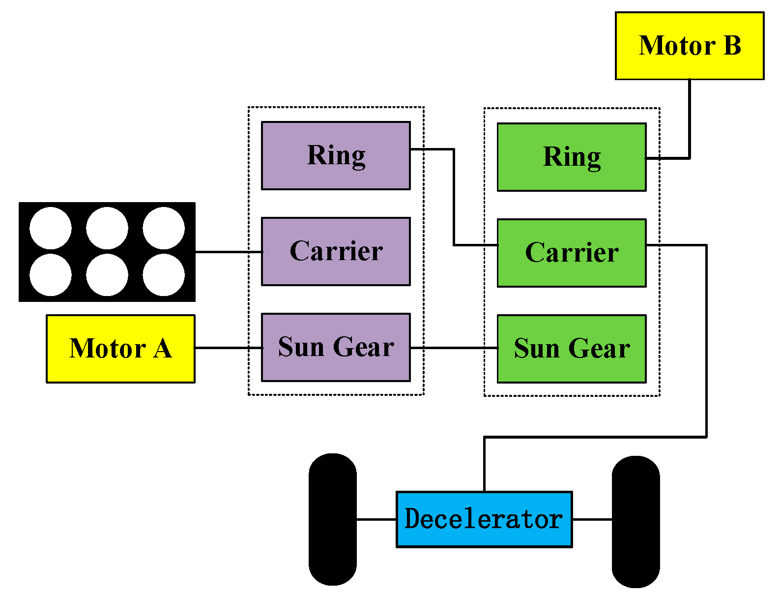
This research focuses on a two-stage planetary transmission system commonly used in automatic transmissions in vehicles. The physical system is shown in
Figure 5. Each planetary line contains a sun gear, a ring gear, a planet carrier, and four planetary gears. The sun gear in the first stage is connected to the sun gear in the second stage, and the carrier in the first stage is connected to the ring gear in the second stage. The power is input from the first stage sun gear shaft and output from the second stage ring gear. Torque is applied to the input terminal and the output terminal as the driving force and load, respectively.
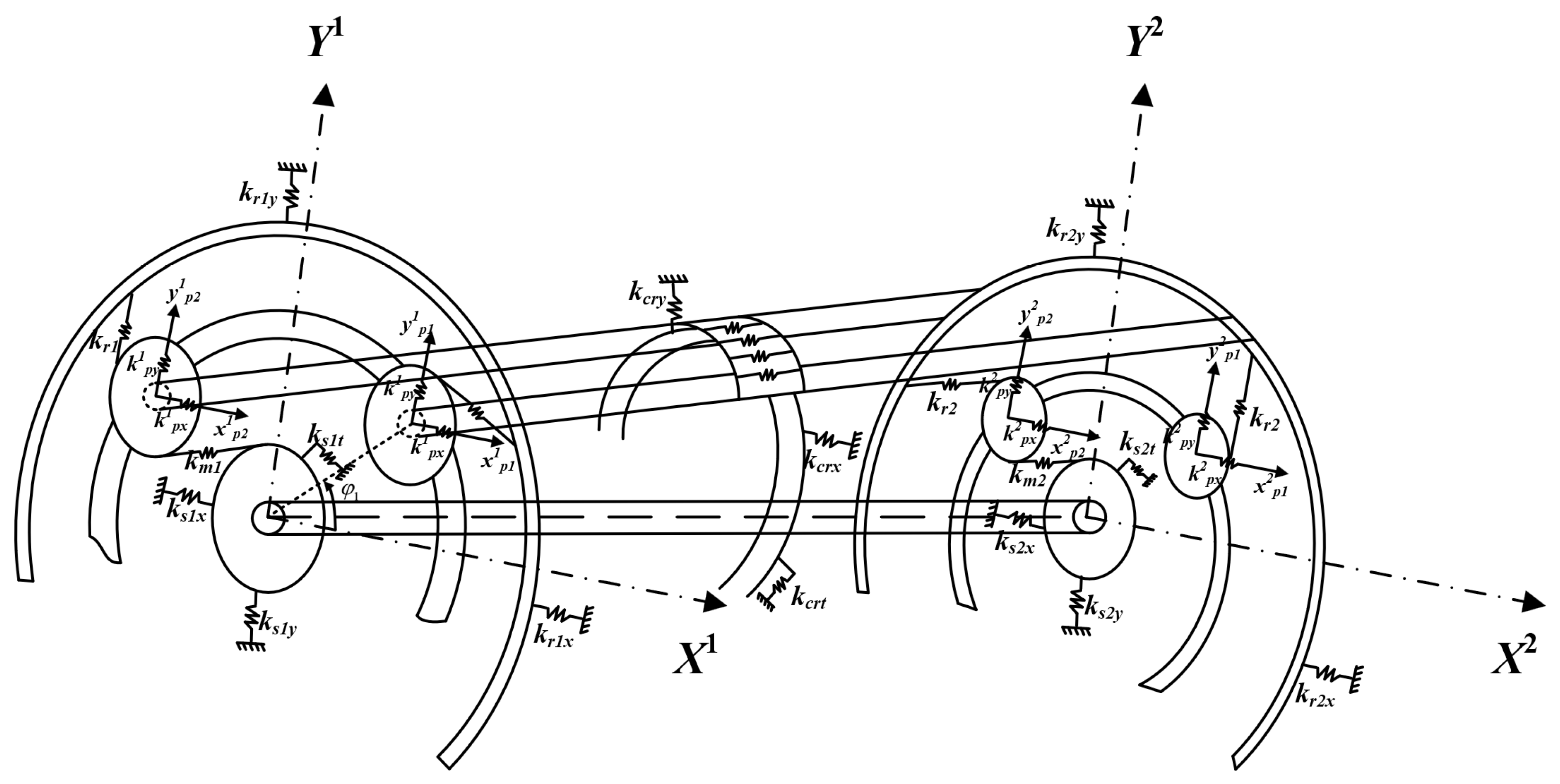
A lumped parameter model for spur planetary gears is shown in
Figure 6. The subscripts
,
,
, and
(
i = 1, 2;
j = 1, 2, 3, 4) represent the
ith stage sun gear, carrier gear, and ring gear and
jth planet gear in the
ith stage, respectively.
,
, and
are the small translational displacement and small angular displacement of component
a (
a =
,
,
,
).
ksipij,
csipij, and
bsipij are the time-varying meshing stiffness, meshing damping, and backlash for sun–planet gear pairs in the
ith stage, respectively, and the means of
kripij,
cripij, and
bripij are similarly defined.
kxa and
kya are the support stiffnesses along the horizontal and vertical axes.
Backlash must be assessed in advance to ensure that a gear pair can work normally. Notably, backlash is a main nonlinear factor in a gear system, and the backlash function of a gear pair can be written as shown in Equation (9); the same function is relevant for a ring gear and planet gear pair.
is the meshing line deformation between the sun gear and planet gear, and
is the backlash. Due to gear installation error, manufacturing error, and displacement, the meshing line length will change. The meshing line deformation variables
and
are included in the mathematical model and can be expressed as
is the variation in the meshing line caused by small torsional displacement, is the variation in meshing line caused by small translational displacement, n = s or r for the sun or ring gear, i = 1 or 2 is the stage of the planet gear system, and j = 1, 2, 3, or 4 for the planet gears.
The meshing line deformation caused by small torsional displacement can be expressed as:
The variation in the meshing line caused by minor displacement
can be expressed as
The nonlinear meshing force can be written as shown in Equation (13).
In Equation (13), and are the time-varying meshing stiffness of the sun–planet gear pair and ring–planet gear pair, respectively.
Then, the equations of motion for the two-stage planet gear system can be written as shown in Equations (14)–(23) according to the Lagrange equations. In these equations, and (a = ) are the mass and inertia of component a.
The differential equation of vibration for the first stage sun gear is
The differential equation of vibration for the first stage ring gear is
The differential equation of vibration for the first stage carrier is
The differential equation of vibration for the first stage planet gear is
The differential equation of vibration for the second stage sun gear is
The differential equation of vibration for the second stage ring gear is
The differential equation of vibration for the second stage carrier is
The differential equation of vibration for the second stage planet gear is
kbs1s2, ks1s2, cs1s2, and cbs1s2 are the bending stiffness, torsional stiffness, bending damping, and torsional damping of the shaft between the sun gears, respectively.
The torsional torque and transverse force of the shaft between the first stage ring gear and the second stage carrier can be expressed by Equation (23).
kbc1r2, kc1r2, cbc1r2, and cc1r2 are the bending stiffness, torsional stiffness, bending damping, and torsional damping of the connecting shaft between the first stage carrier and second stage ring gear, respectively.
3.2. Analysis of the Tuning Mechanisms of Different Models
The symmetrical arrangement of the planetary transmission system makes the meshing positions symmetrical, and this relation is the source of phase tuning. The meshing force itself is a complex nonlinear periodic function. To study the coupled phase-tuning relationships in the two-stage planetary transmission system, starting from the meshing force, the characteristics of excitation forces acting on central components at all levels were analysed, and the component locations were assessed. The characteristics of the resultant force or the resultant moment were obtained to determine the coupled vibration mode and law for the central part of the two-stage planetary transmission system. In the following description, positive direction refers to the clockwise direction, and negative direction refers to the counter-clockwise direction. Three tuning models are established, and the specific tuning parameters are shown in
Table 2.
3.2.1. Model 1: Coupled Tuning Mechanism Analysis
The two-stage planetary transmission system in model 1 displays meshing phase differences, and these differences are listed in
Table 3;
and
represent the meshing phase difference of S–P and R–P, respectively.
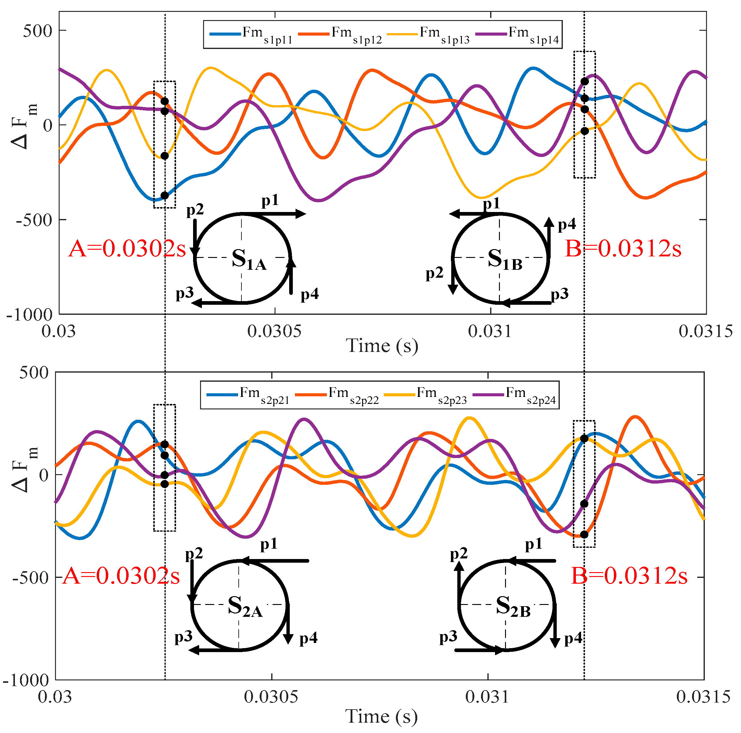
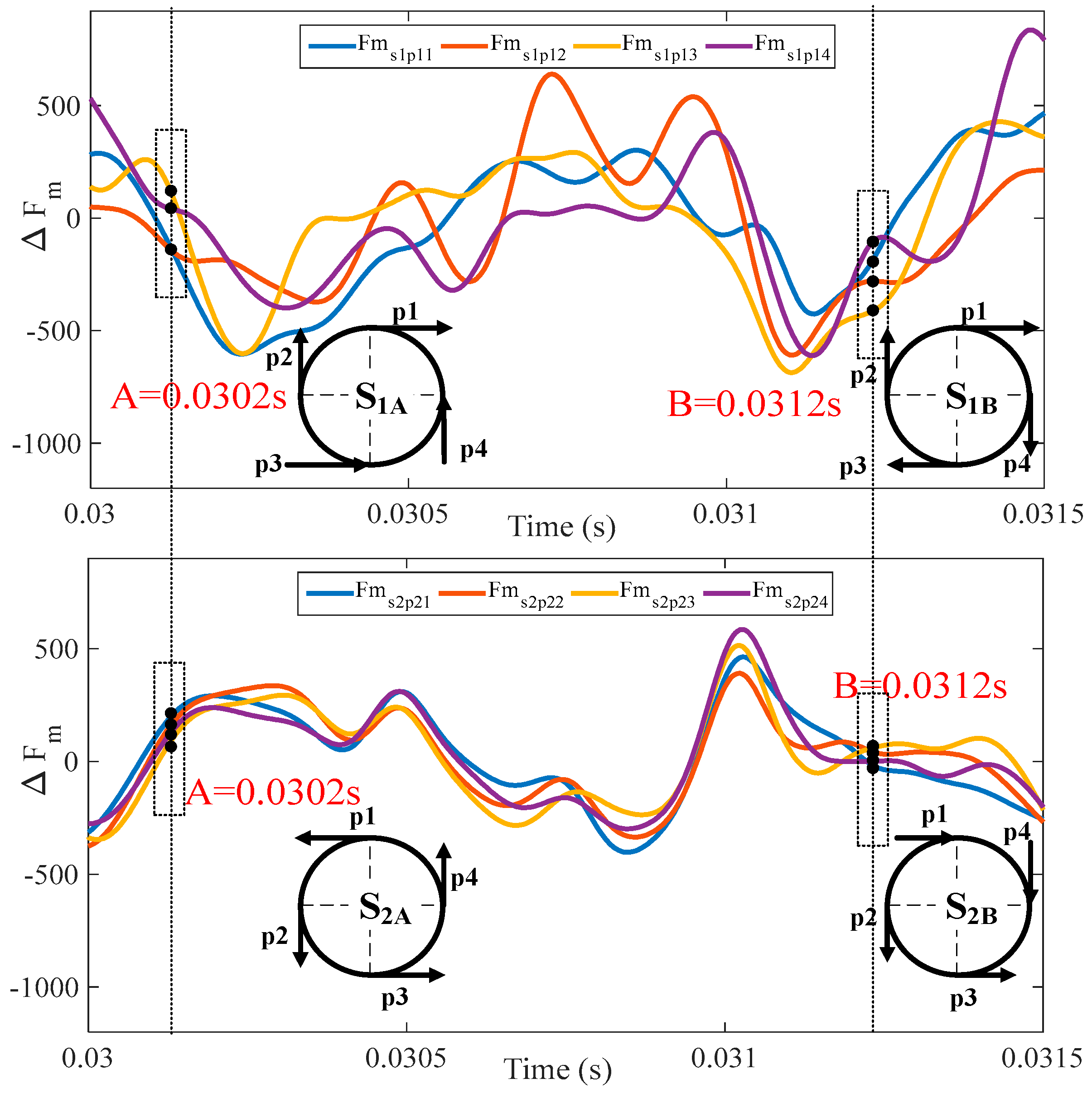
Figure 7 shows the time-domain curve of the fluctuating meshing force of the sun gears in each stage in mode 1 and the instantaneous force diagram at time points A and B. The time-domain curve shows that the direction and magnitude of the meshing force between each planetary gear and the sun gear change over time. Consequently, the resultant force acting on the sun gear is converted from a lateral force to a torsional moment, resulting in the transient vibration of the sun gear.
To further analyse the fluctuating meshing force of sun gears at different times, the time points A = 0.0302 s and B = 0.0312 s were selected, and the corresponding force diagrams were obtained. In
Figure 7,
indicates the fluctuating meshing force for S–P gear pairs, where
i = 1, 2 and
n = 1, 2, 3, 4 indicate the stage number and the number of planet gears, respectively; the two black dotted lines correspond to A = 0.0302 s and B = 0.0312 s. The instantaneous meshing force diagrams between four planetary gears and the sun gear are shown below the dotted frame, where S
1A represents the force diagram of the sun gear in the first stage at time point A, with similar expressions for others.
S1A and S2A are taken as examples to illustrate the relationship between the force on the sun gear and the vibration mode in mode 1. For S1A, the meshing forces of the four planetary gears are represented by p1, p2, p3, and p4. If , then these four forces will cancel each other, and the sun gear will maintain the TS and TE vibration modes; if , then the RE mode will be triggered. For S2A, the force directions of p1 and p3 are the same, as are those of p2 and p4; therefore, the TE mode of translational vibration for the sun gear is directly excited.
The above analysis indicates that when the two-stage planetary transmission system exhibits a phase difference, the vibration mode of the central part of the system switches between translational vibration, torsional vibration, and equilibrium based on the relevant forces. Due to the periodicity of the meshing force, the vibration mode of the central part of the system also periodically varies.
3.2.2. Model 2: Coupled Tuning Mechanism Analysis
In model 2, the meshing phase differences in the first stage and second stage are zero, and these differences are listed in
Table 4;
and
represent the meshing phase differences of S–P and R–P, respectively.
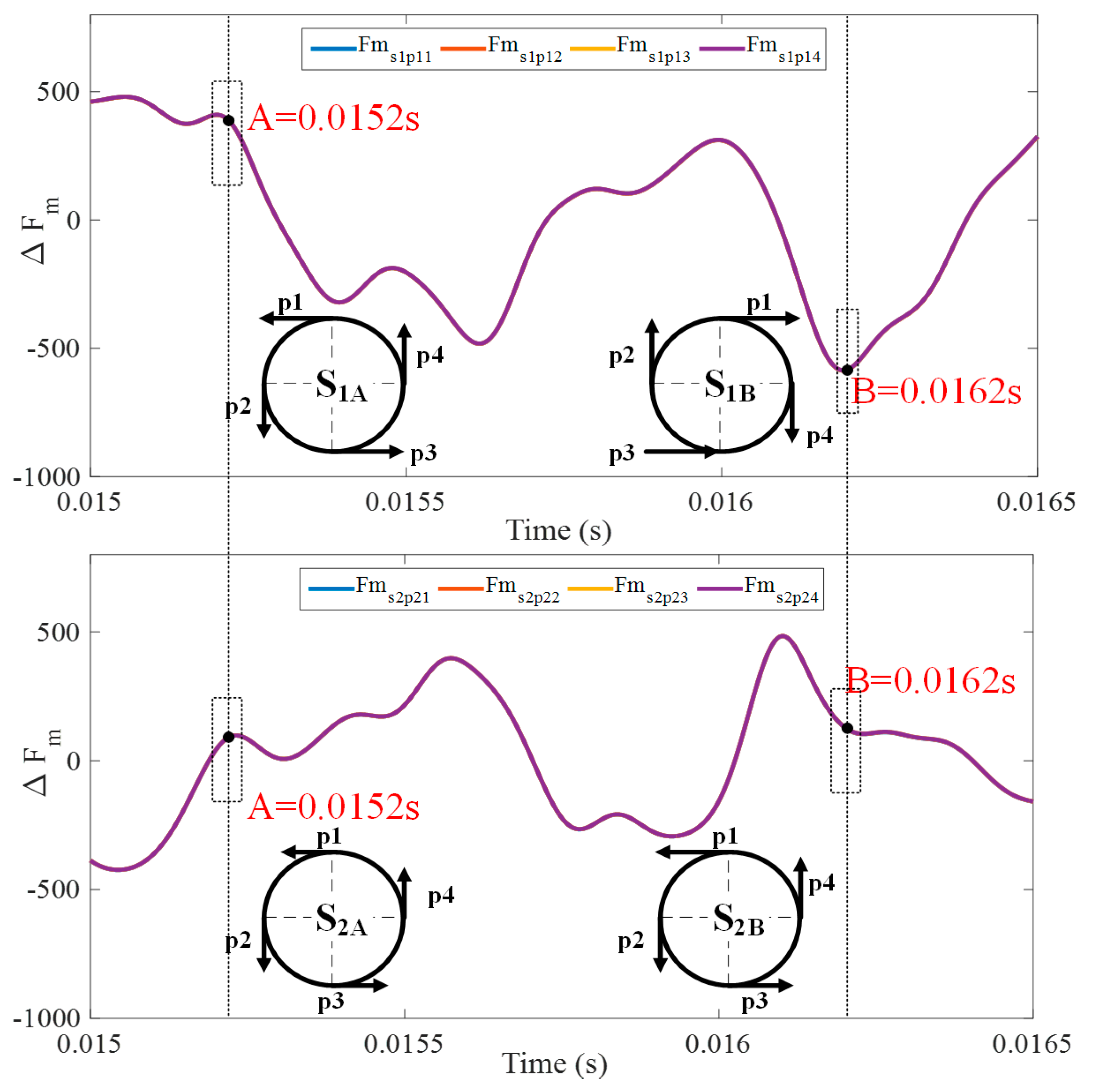
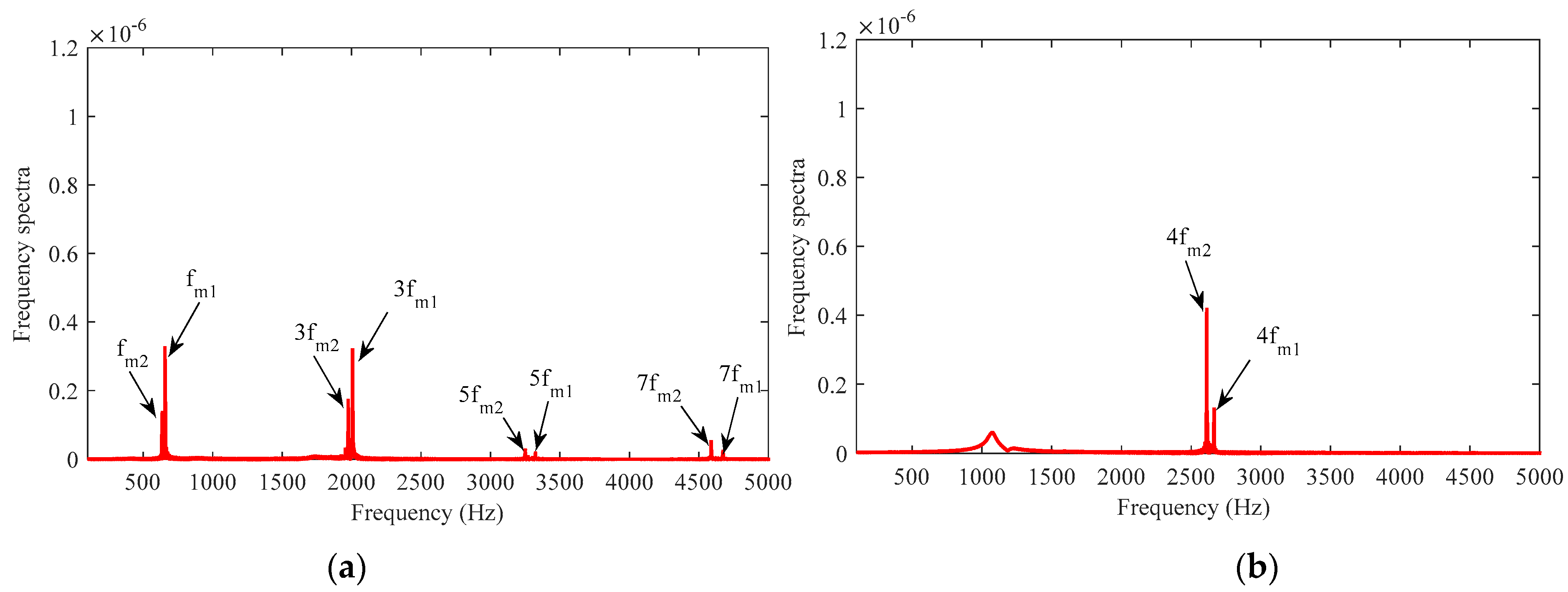
Figure 8 shows the time-domain curve of the fluctuating meshing force in each stage for sun gears in mode 2 and the instantaneous force diagram at time points A and B. The time-domain curve shows that the direction and magnitude of the meshing force between each planetary gear and the sun gear are the same; therefore, the force acting on the sun gear always includes a torsional torque component, leading to the torsional vibration of the sun gear.
To further analyse the fluctuating meshing force acting on the sun gear at different times, the time points A = 0.0152 s and B = 0.0162 s were selected, and the corresponding force diagrams were obtained. S1A is taken as an example to illustrate the relationship between the force on the sun gear and the vibration mode in mode 2. For S1A, the meshing forces of the four planetary gears are represented by p1, p2, p3, and p4, and their direction and magnitude are the same (i.e., ); then, these four forces form a torsional torque, which directly excites the RE mode of torsional vibration for the sun gear. According to the above analysis, when the phase difference between the two planetary transmission systems is 0, the vibration mode of the centre part of the system is dominated by torsional vibration.
3.2.3. Model 3: Coupled Tuning Mechanism Analysis
In model 3, the meshing phase differences in the first stage and second stage are listed in
Table 5;
and
represent the meshing phase differences of S–P and R–P, respectively.
Figure 9 shows the time-domain curve of the fluctuating meshing force for each stage of the sun gears in mode 3 and the instantaneous force diagram at time points A and B. The time-domain curve shows that the direction and magnitude of the meshing force between each planetary gear and the sun gear change over time, resulting in the force acting on the sun gear being converted between a lateral force and torsional moment; consequently, the vibration mode of the sun gear is a couple mode.
To further analyse the fluctuating meshing force on the sun gear at different times, the time points A = 0.0302 s and B = 0.0312 s were selected, and the corresponding force diagrams were obtained. The two black dotted lines correspond to A = 0.0302 s and B = 0.0312 s.
S1B and S2B are taken as examples to illustrate the relationship between the force on the sun gear and the vibration mode in mode 3. For S1B, the meshing forces of the four planetary gears are represented by p1, p2, p3, and p4, and their directions are the same (counter clockwise). Regardless of whether the magnitude is the same, these four forces will form a torsional torque, which directly excites the RE mode of torsional vibration for the sun gear. For S2B, the force directions of p1 and p3 are the same, as are those of p2 and p4; therefore, the TE mode of translational vibration for the sun gear is directly excited.
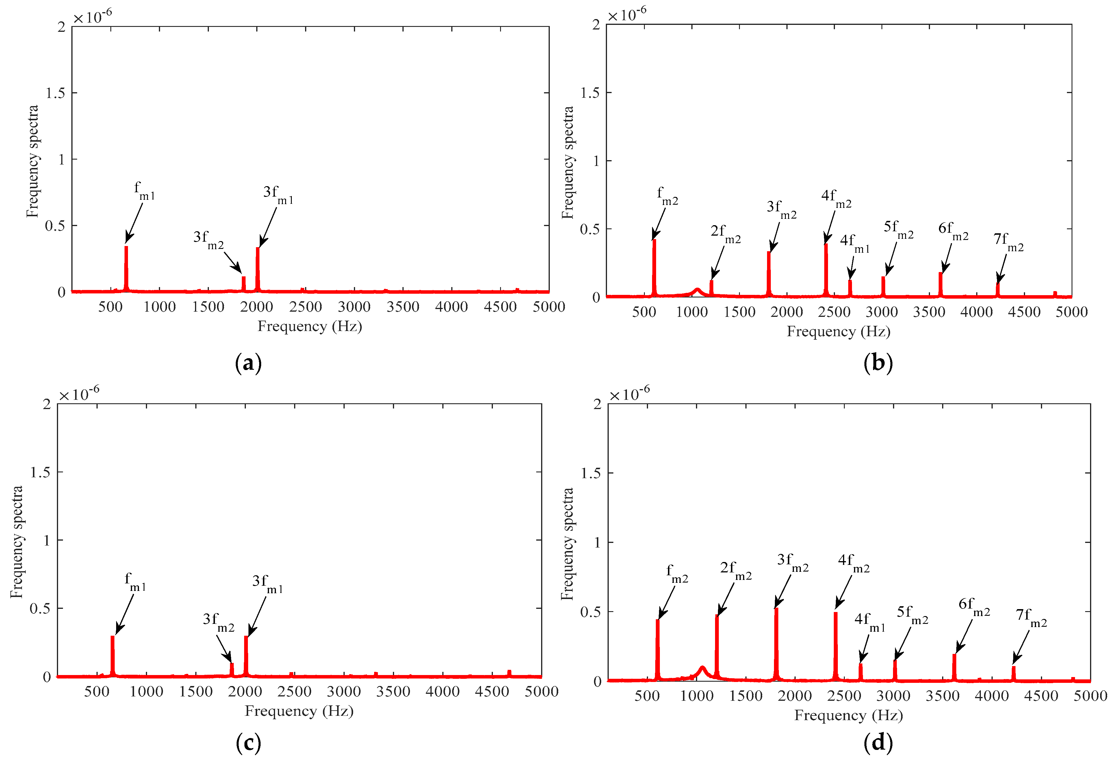
Based on the above analytical comparison to a single-stage planetary system, the phase tuning of the two-stage planetary transmission system has strong coupling characteristics, and due to this coupling, the vibration characteristics of the two-stage planetary transmission system can significantly vary. In mode 1, the magnitude and direction of the fluctuating meshing forces on the sun gear change with time, and because the direction of the force is inconsistent, the torsional moment cannot be directly formed, so translational vibration is dominant. In mode 2, the magnitude and direction of the fluctuating meshing forces on the sun gear are always consistent, directly leading to torsional torque and stimulating the torsional vibration mode of the system. In mode 3, when the tuning modes in the first and second stages are different, the tuning of the sun gear differs from that in a single-stage system, and a coupled tuning phenomenon appears. Theoretically, the force characteristics of the sun gear in the first stage should be the same as those in mode 1. However, under the coupled effect of secondstage tuning, the directions of the fluctuating meshing forces on the sun gear in the first stage gradually become the same, resulting in torque action, which directly excites torsional vibration. Similarly, the second stage sun gear is theoretically influenced by torsional vibration only. Additionally, under the coupled tuning effect in the first stage, the direction of the fluctuating meshing forces on the sun gear gradually changes and can even reverse the forces, thus producing a lateral resultant force and exciting the lateral vibration.
