Abstract
The vibro-acoustic performance of a fluid-loaded periodic locally resonant (LR) plate was examined in this research, with a specific focus on the effect of water fluid on the vibration and sound radiation of the LR structure. The analytical models of the fluid-loaded LR plate’s band gap, vibration, and acoustic radiation were theoretically derived with closed-form solutions, which can be used to predict the general vibro-acoustic rules of underwater LR structure. The results show that the LR band-gap width and Bragg frequency are significantly reduced when water fluid is considered. Besides, the frequency range that can be tuned to control the vibration and sound radiation for the LR plate with fluid is much narrower than that without fluid. The reason for inducing the above effects was also given in this research, which can be physically explained by the attached mass caused by the water fluid. In addition, the reason for the enhanced radiation efficiency close above the band gap was also discussed, which is caused by the change of radiation mode from corner or edge radiation to monopole radiation. Furthermore, adding small damping into the resonator could reduce the vibration and sound radiation in the frequency range above or close below the band gap, inducing the attenuation zone to be significantly broadened. Thus, designing the periodic resonators with proper damping could be an efficient method to make the LR plate more beneficial for vibration and noise reduction in water-surrounding applications.
1. Introduction
In the past two decades, artificial periodic structures composed of repeated units have gained more and more attention. The periodicity of the artificial periodic structure makes it have passbands and forbidden bands, presenting filtering characteristics, thus providing a new way to control structure vibration and noise radiation [1,2,3]. As early as 1946, L. Brillouin systematically reviewed the previous studies and elaborated the basic modeling theory of the traditional periodic structures [4]. In 1993, M. S. Kushwaha et al. proposed the concept of phononic crystals for the first time when they were studying periodic composite materials [5], which objectively inspired and activated the study of periodic band gaps.
The band-gap generation mechanism found in early research is Bragg scattering, which can only control the propagation of elastic waves or acoustic waves with a wavelength scale comparable to the lattice constant. However, it is challenging to control low-frequency vibration or noise. In 2000, Liu et al. first clearly proposed the mechanism of local resonance [6], the discovery of which provides a low-frequency vibro-acoustic suppression method in principle, and the controllable wavelength is generally 1–2 orders of magnitude larger than the lattice constant. In the case of the same cell size, the local resonance mechanism can achieve a lower frequency bandgap than the Bragg scattering mechanism, which allows the realization of low-frequency vibration attenuation and noise reduction. Because of its attractive application prospect in vibration attenuation and noise reduction, the local resonance mechanism has developed rapidly [1,2,3,7] in the last two decades. In order to obtain a comprehensive understanding of the LR structure’s vibrational and acoustic properties, various aspects have been considered and thoroughly studied, including multiple band gaps formation methods, LR structure type designs, band structure calculation methods, etc.
In initial studies, LR units were generally designed with a single degree of freedom, enabling a single complete band gap. With the deepening of research, multi-degree-of-freedom LR structures have gradually emerged to achieve multiple band-gap characteristics. Q. Wen et al. studied the bending-vibration band structure of a one-dimensional phononic crystal beam composed of periodic resonators with two degrees of freedom, resulting in more abundant and broader band gaps, which is beneficial to multiple-frequency vibration reduction [8]. J. Wu et al. extended the one-dimensional beam to a more complicated two-dimensional pate [9], and some other researchers have also conducted related multi-degree-of-freedom research [10,11,12,13,14,15]. In addition, nonlinear LR structures [16,17,18,19,20] have also gained extensive attention, broadening the local resonance mechanism’s research scope. A variety of methods have also been developed to calculate the band gaps and transmission characteristics of LR structures, including the transfer matrix method [8], plane wave expansion method [10], finite-element method [21,22,23], multiple scattering method [24], lumped mass method [25], finite-difference time-domain (FDTD) method [26], etc. For the installation design of LR elements in practical applications, a series of configuration types have been proposed [9,27], where the resonators were inserted into the plate’s periodic openings [28,29,30,31,32], mounted at the plate’s surface [12,33,34], or embedded into the inner of the base structures [35]. Furthermore, the studies of local resonance mechanism were also extended from discrete lattice structure to continuous elastic structure, from elastic waves to acoustic waves, and from vibration-control to noise-control purposes.
The LR structure can not only attenuate vibration but can also reduce noise radiation. With the increasing demand for cabin interior noise reduction, F. Casadei et al. focused on the structural–acoustic coupling performance of the LR structure with a periodic array of resistive–inductive shunted piezoelectric patches to reduce cabin noise [36]. By comparing the in-vacuo and air–fluid-loaded results, it was found that the dispersion relations of the plate can be computed without introducing an unacceptable error if the air–fluid load is neglected. Followed by F. Casadei, A. Aladwani et al. also investigated the structural vibration of the LR plate and the acoustic radiation in an adjacent acoustic cavity to control the vibration and noise simultaneously [37]. Apart from the interior noise reduction of the cavity adjacent to the LR structure, the sound radiation performance in the exterior infinite free space was also examined [38], specifically focusing on the characteristics of radiation efficiency. The authors of the present research also extended the vibro-acoustic research to the LR structures with sandwich units [39], periodic multiple resonators [14], and local lateral resonators [15]. Like the above studies, many works about the flexural-wave band-gap properties and vibro-acoustic performance of LR structures have been conducted. However, these studies mainly consider the situation in the vacuum or air, which mostly ignores the effect of fluid medium on the LR structure or only considers light-fluid weak coupling between vibration and radiation sound. Thus, the band-gap properties and vibro-acoustic performance of the LR structure surrounded in heavy fluid need to be further researched. Therefore, the research topic of this study is focused on the flexural-wave band gap of a periodic locally resonant plate in heavy fluid medium to broaden the research domain of locally resonant mechanisms.
Vibration attenuation and noise reduction are of great concern for water-surrounding complex equipment [40], where excessive vibration and noise will affect the performance of precision instruments, passenger comfort, and even the safety of underwater vehicles. With the development of noise reduction technology, the vibration and noise in the middle- or high-frequency range can be reduced by using the methods of vibration isolation, damping treatment, sound absorption, sound insulation, etc. However, reducing low-frequency vibration and noise is still challenging for water-surrounding structures, especially for large equipment. Thus, the LR structure has great potential in water-surrounding applications because of its sub-wavelength tunable band gap. For the published underwater local-resonance research, most studies are mainly related to sound absorption [29,41] or sound insulation [42]. However, the properties of flexural-wave-induced sound radiation of underwater LR structures remain unknown, and the effect of heavy water fluid on flexural-wave vibro-acoustic performance needs to be revealed. In the above vibro-acoustic research related to exterior infinite free space [14,15,38,39], the uncoupled vibro-acoustic models were used with the coupling between structure and fluid neglected. The physical models are only appropriate for air-surrounding applications but are inappropriate for water-surrounding applications because of strong structure–fluid coupling. Therefore, the vibro-acoustic performance of the fluid-loaded LR structure needs to be further researched.
In this research, the vibro-acoustic performance of a fluid-loaded periodic LR plate was examined. The coupling of structure and water fluid was considered to meet the requirements in underwater applications. The analytical models of the band gap, vibration, and acoustic radiation of fluid-loaded LR plate were theoretically derived with closed-form solutions, which can be used to predict the general vibro-acoustic rules of underwater LR structure. The effects of water–fluid load on the band structure, vibration response, and sound radiation were thoroughly studied, and the corresponding physical mechanism was also analyzed. The findings in this research could provide helpful guidance for vibration attenuation and noise reduction using local resonance mechanisms in underwater applications.
2. Theoretical Models
2.1. Structure Model and Basic Governing Equations
A periodic LR plate with one side submerged in a heavy fluid is considered in this research. The periodic LR plate comprises a uniform base plate and periodic LR units, where a unit element is shown in Figure 1a. The resonator consists of a mass block with mass and a linear spring with spring stiffness . The linear spring connects the mass block and the uniform base plate. The LR plate’s unit element has the dimensions of length , width , and thickness . Figure 1b shows the first Brillouin zone of the unit element, which can be used to calculate the band structure.
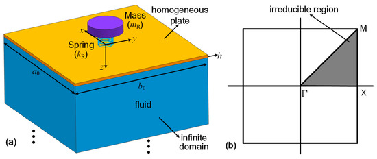
Figure 1.
(a) Configuration of a unit element and (b) the first Brillouin zone.
In the following theoretical model, a harmonic motion with a time-dependence term is considered in the model. For simplicity, the time-dependence term is not given throughout the study. The differential equation of motion of the LR plate single-side submerged in water can be given as
where , is transverse displacement, is density, is thickness, and is angular frequency. The bending rigidity is expressed as , where and are the uniform plate’s Young’s modulus and Poisson’s ratio, respectively. The force term in Equation (1) represents the external force applied on the surface of the plate. In the band-gap calculation model, this part is neglected.
The force term in Equation (1) represents the force from the resonator and can be written as , in which is the force amplitude applied at the resonator position and is the Dirac delta function. The force analysis on a resonator coupling with a uniform plate unit shows that
where and are the transverse displacement of the plate at position and the displacement of the resonator’s mass block, respectively.
The force term in Equation (1) represents the acting force induced by the motion of the water fluid. In the overall fluid domain, the Helmholtz wave equation in a Cartesian coordinate system can be expressed as
where is the acoustic wave number and is the fluid medium’s sound velocity. The continuity condition for the normal velocity at the interface between the plate surface and fluid medium states that
where is the density of the fluid medium and is the normal velocity of the plate.
2.2. Band-Gap Formulations of an Infinite LR Plate
The plane wave expansion method was used to acquire the dispersion curves of the single-side submerged infinite LR plate. For the considered structure, infinite resonators are periodically located along the x- and y-directions, and the total force generated by the periodic resonators on the uniform base plate can be given as
where (, ) is the location of the st resonator and is the force applied on the uniform plate by the st resonator. According to Equation (2), the vibrational governing equation of the st resonator can be written as
where is the transverse displacement of the plate at location (, ) and is the displacement of the st resonator. The force can be expressed as
According to the plane wave expansion method, the transverse displacement of the LR plate can be written as
where , , is the specified Bloch wave vector, and is the reciprocal-lattice vector of the mn plane wave, in which and .
According to the Bloch theorem, it can be obtained that
where is the transverse displacement of the plate at location (0, 0) and is the displacement of the resonator located in position (0, 0). Substituting Equations (7) and (9) into Equation (5) yields
According to the characteristics of the Dirac delta function , Equation (10) can be further expressed as
As is a periodic function in a continuous periodic system, it can be expressed in the form of Fourier series
Multiplying at both sides of Equation (12) and integrating over the area of gives that , where . Thus, Equation (11) is simplified as
According to Equation (8), the displacement can be expressed as
In the infinite fluid domain, the acoustic pressure solution of Equation (3) can be assumed as
Substitution of Equation (15) into Equation (3) yields
Thus, the wavenumber along the z-direction can be given as
By substituting Equation (15) into Equation (4), it can be obtained that
As the surface velocity can be represented by the transverse displacement with the equation of , Equation (18) can be further expressed as
By substituting Equation (8) into Equation (19), the expansion coefficients of acoustic pressure can be given as
Thus, the acoustic pressure in the infinite fluid can be given by substituting Equation (20) into Equation (15), which can be expressed as
The pressure applied on the plate generated by the fluid medium can be given as
By substituting Equations (8), (9), (13), (14) and (22) into Equations (1) and (6), it can be obtained that
By multiplying at both sides of the first equation in Equation (23), integrating over the area of , replacing subscripts and with and for convenience, and making the infinite series in Equation (23) be truncated to and , Equation (23) can be further expressed as
After further manipulations, Equation (24) can be written in the matrix form as
where and . For each given Bloch wave vector , the characteristic frequencies can be determined by Equation (25). By sweeping in the directions of (, ), (, ), and (, ) in the first Brillouin zone (see Figure 1b), the dispersion relationship between wave number and frequency can be obtained, from which the band gap is then identified.
2.3. Vibration and Radiation Formulations of a Finite LR Plate
A finite LR plate subjected to a harmonic point force with simply supported boundary condition is placed in an infinite rigid baffle and single-side submerged in the infinite water fluid, as shown in Figure 2. The calculation model of vibration and sound radiation of this coupling system is established with consideration of the effects of fluid load.
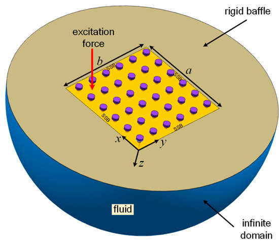
Figure 2.
Schematic of a finite locally resonant plate baffled in an infinite rigid baffle and single-side submerged in the infinite fluid (SSB: simply supported boundary).
For the finite LR plate with a simply supported boundary, the flexural displacement can be assumed as
where and .
For a point force applied at position , the external force in Equation (1) can be expressed as , where is the force amplitude. The force term can also be expressed in the form of the Fourier series
where .
For the considered structure, the resonators are periodically located along the x- and y-directions, with the number of resonators labeled as and , respectively. Thus, the force generated by the periodic resonators on the uniform base plate in Equation (1) can be given as
where (, ) is the location of the st resonator and is the force applied on the uniform plate by the st resonator, which can be expressed in Equation (7). Equation (28) can also be expressed as the form of the Fourier series
where . Substituting Equation (26) into Equation (7) yields
Following that, by substituting Equation (30) into Equation (29), it can be obtained that
According to the Rayleigh integral method, the acting force induced by the motion of fluid in Equation (1) can be given as
where , is the surface velocity of the plate and can be expressed as
Thus, Equation (32) can be further expressed as
The force terms , , and on the right side of Equation (1) have been expressed in the Fourier series, as shown in Equations (27), (29) and (34). By substituting these equations and Equation (26) into Equation (1), it can be obtained that
By multiplying at both sides of Equation (35), integrating over the area of , replacing subscripts and with and for convenience, and making the infinite series in Equation (35) be truncated to and , Equation (35) can be further expressed as
where , in which is the radiation resistance and is the radiation reactance. The radiation resistance and reactance can be expressed as
Substituting Equation (26) into Equation (6) and making the infinite series truncated to and gives
Equations (36) and (38) can be rearranged in the matrix form as
where , , and .
The coefficient can be determined by giving the frequency and the force amplitude . After becoming known, the LR plate’s displacement response can finally be determined using Equation (26), from which the transverse velocity can be obtained as , where . The spatially averaged mean square velocity can be calculated as
where the superscript asterisk denotes the complex conjugate of a variable. The total acoustic radiation power from the finite LR plate can be given as [43]
from which the acoustic radiation power can finally be determined to illustrate the radiation performance caused by the coupling effect among the resonators, plate, and fluid. The average radiation efficiency of the LR plate can then be given by
3. Results and Discussion
The dimensions of a unit element in the calculated LR plate are set as and . The base plate is made of steel with Young’s modulus , density , and Poisson’s ratio . The mass of the resonator is set as 0.0078 kg, which is 20% of the mass of a base plate element. The resonator is tuned to 514.0 Hz with the spring stiffness set as . The density and sound velocity of the water fluid medium were set as and , respectively. For air medium, the density and sound velocity were set as and , respectively. The above parameters were kept unchanged in the following analysis unless otherwise stated.
3.1. Band-Gap Properties
The dispersion curves of an infinite water-loaded LR plate with the parameters given above were calculated using the theory derived in Section 2.2. In order to validate the theoretical formulations, a finite-element-method (FEM) model was also established with COMSOL Multiphysics software. The dispersion curves from the analytical and FEM models are shown together in Figure 3.
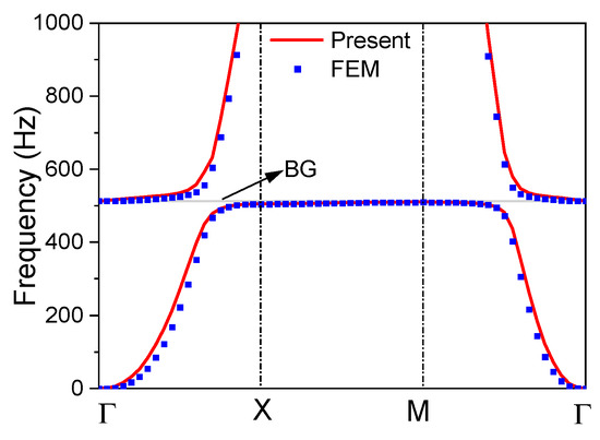
Figure 3.
Dispersion curves of the water-loaded locally resonant plate and corresponding band gap (BG).
It can be seen from Figure 3 that the dispersion curves calculated by the present model agree very well with the results from the FEM model. The band-gap frequency ranges calculated from the two models are compared in Table 1, which shows that the band-gap start frequency, cut-off frequency, and bandwidth of the analytical results are pretty close to the FEM results.

Table 1.
Band gap comparison between the present model and the FEM model.
In order to examine the effect of water fluid on the band-gap properties of the LR plate, the dispersion curves and band-gap frequency ranges of the LR plate without fluid load and with air load were also calculated and are shown in Figure 4 and Table 2.
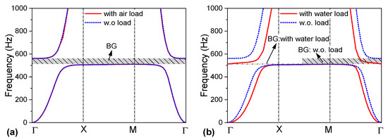
Figure 4.
Dispersion curves of the locally resonant plate (a) with air load and without load, and (b) with water load and without load (w.o.: without, BG: band gap).

Table 2.
Band gaps of the locally resonant plate with air/water load and without load.
As shown in Figure 4a and Table 2, the air-loaded LR plate’s dispersion curves and band-gap frequency range nearly coincide with the results of the unloaded plate. It indicates that the effect of air load on the band-gap properties can be neglected due to weak structure–fluid coupling. It can also be observed from Figure 4b and Table 2 that, unlike air load, the water load significantly affects the band-gap properties. The band-gap start frequency of the water-loaded LR plate keeps the same as that of the unloaded plate, while the band-gap cut-off frequency is significantly reduced when water load is considered, resulting in the band-gap width of the water-loaded LR plate decreasing to 2.7 Hz from 51.5 Hz.
The above results show that the band-gap property of LR structure in the underwater environment is quite different from that in the air. More specifically, the vibration–reduction effect will be significantly reduced, and band-gap width may decrease to approximately 5% of that in the air environment. Thus, if the purpose is to use LR structure in underwater applications, the effect of water load must be considered.
In fact, the phenomenon that the water-loaded LR structure provides a narrow band gap can be physically explained by the attached mass caused by the fluid. Owing to the strong vibro-acoustic coupling between the plate and surrounding water fluid, the effective density of the base plate could be increased significantly. From Equation (24), the effective density of the base plate covered with water fluid can be approximately given as
where is the structural wave number, and can be given as when a single plane wave is considered (). For simplicity, the normalized effective density is used and defined as , where is the density of the base plate. The normalized effective densities of the LR plate with water load and without fluid load are shown in Figure 5b, and corresponding dispersion curves are given in Figure 5a for comparison purposes.
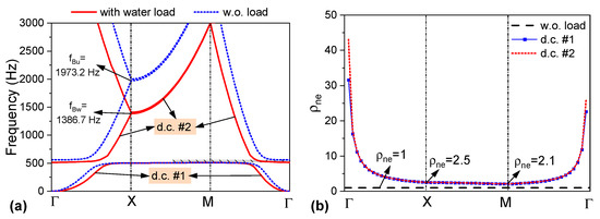
Figure 5.
(a) Dispersion curves of the LR plate with water load and without (w.o.) fluid load; (b) normalized effective density (d.c.: dispersion curve).
As shown in Figure 5b, the normalized effective densities of dispersion curve #1 and dispersion curve #2 perform with a similar variation trend. The effect of water fluid on normalized effective density varies with the wave number and frequency. The curve decreases rapidly from to X, decreases slightly from X to M, and increases rapidly from M to . Thus, the water fluid provides a significant attached mass in both dispersion curves #1 and #2, and the corresponding normalized effective density reaches as much as infinite at position .
In order to further explain the attached mass’s characteristics, the normalized effective density of the water-loaded LR plate as a function of frequency is given in Figure 6, together with the water-loaded homogeneous (HM) plate without LR units for comparison purposes. As shown in Figure 6, the normalized effective density of the water-loaded HM plate decreases with increasing frequency, indicating that the water fluid provides a significant attached mass in the low frequency and a slight attached mass in the high frequency. The normalized effective density curve of the water-loaded LR plate has the same variation trend as that of the HM plate, except for the frequencies near the resonant frequency. In the frequency range of 191.3~510.1 Hz below the band gap, the normalized effective density of the LR plate is slightly smaller than that of the homogeneous plate. While above the band gap is between 512.8 Hz and 530.0 Hz, the normalized effective density of the LR plate is significantly increased, induced by both the fluid and the LR units.
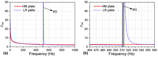
Figure 6.
Normalized effective density with water load as a function of frequency with frequency range (a) from 0 Hz to 1 kHz and (b) from 460 Hz to 560 Hz (BG: band gap; HM: homogeneous; LR: locally resonant).
The increased attached mass caused by the water fluid will affect the upper frequency of the band gap. The study by C. Sugino et al. has shown that the upper frequency of the band gap can be approximately given as [44], where is the mass of the resonator and is the mass of the base plate in a single LR plate unit. This expression can be deduced from a single plane wave assumption () instead of the superposition of multiple plane waves and thus is only an approximate estimation. However, it can give us a clear understanding of the band-gap characteristics. This expression indicates that the upper frequency decreases with the increase of . For the LR plate with water–fluid load, the upper frequency can be approximately given as . For the parameters given in the first part of Section 3, the upper frequency as a function of is shown in Figure 7.
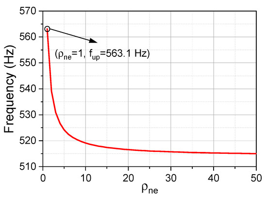
Figure 7.
The upper frequency of the band gap as a function of normalized effective density.
As shown in Figure 7, the upper frequency of the band gap decreases with the increase of normalized effective density. When , the estimated frequency is 563.1 Hz, which is quite close to the accurate results of the unloaded LR plate shown in Table 2 (561.6 Hz). When exceeds 30, tends to the resonator’s resonant frequency (514.0 Hz) and is close to the upper frequency calculated in Table 2 (512.8 Hz).
As illustrated above, the water fluid introduces an attached mass on the base plate, resulting in a significant increase of the effective density in the frequency range near the resonant frequency, which decreases the upper frequency significantly. However, the lower frequency of the band gap stays almost unchanged when water fluid is introduced, as shown in Table 2. Therefore, the band-gap width of the water-loaded LR plate is significantly decreased compared with the unloaded LR plate.
In fact, the water fluid will also affect the Bragg frequency, which may be the maximum limit of the upper frequency. The Bragg frequency can be calculated using the formulation , corresponding to a half wavelength in a unit length. For the plate without fluid load, the expression of Bragg frequency can be given as [45]
For the parameters given in the first part of Section 3, the Bragg frequency is calculated as by using Equation (44). For the water-loaded plate, the dispersion formulation can be given as
This expression can also be written in the following form
By setting , the Bragg frequency of the water-loaded plate can be given as
As is a function dependent on frequency, the Bragg frequency’s explicit expression is difficult to acquire. However, we can determine this with numerical calculation by rearranging Equation (45), which states that
where . By setting in Equation (48) and calculating the unary cubic equation, the Bragg frequency of the water-loaded plate can finally be acquired. For the parameters given in the first part of Section 3, the Bragg frequency is calculated as , and the corresponding effective density is 15,792.5 kg/m3, approximately twice that of the base plate’s density. As shown above, the introduction of water fluid decreases the Bragg frequency from 1973.2 Hz to 1386.7 Hz, and this decrease is also caused by the attached mass. By comparing Equation (44) to (47), a general relation of Bragg frequency between the plate with water fluid and without fluid can be given as
which can be used to estimate the affection degree of water fluid on Bragg frequency.
Figure 8 shows the band-gap frequency and bandwidth of the LR plate with and without water fluid load as a function of the resonant frequency . As shown in Figure 8a, the lower band-gap frequency increases with increasing resonant frequency for the LR plate without fluid. In contrast, the upper band-gap frequency first increases and then keeps at a constant value of 1973.2 Hz, which is exactly the Bragg frequency . As a result, the band-gap width of the LR plate without fluid first increases and then decreases with the increase of , reaching the maximum at approximately 1800 Hz. The band-gap frequency and the band-gap width curves of the LR plate with fluid have the same variation tendency as that of the plate without fluid, except that its upper band-gap frequency and band-gap width are significantly reduced. The frequency range that can be tuned to control vibration for the LR plate with fluid is 0~1500 Hz, which is inferior to that without fluid, providing the frequency range of 0~2340 Hz.
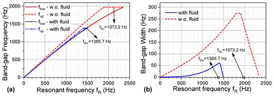
Figure 8.
(a) Band-gap frequency and (b) band-gap width of the locally resonant plate with and without (w.o.) water fluid as a function of the resonant frequency.
3.2. Vibration and Sound Radiation Performance
The vibration and sound radiation of a finite LR plate with simply supported boundary conditions are further studied in this section to examine the vibro-acoustic performance of the LR plate in underwater surroundings. The considered structure is composed of 10 × 8 units (0.5 m × 0.4 m), with each cell’s parameters keeping the same as those shown in the first part of Section 3, except that the damping loss factor of the base plate is set as . A transverse point force with harmonic form is applied at position (0.1 m, 0.1 m).
The root-mean-square velocity averaged over the plate surface was used to examine the vibration performance and is given in decibel form, where the reference velocity is . The radiation power level is also calculated with the reference given as . Both the average velocity level and radiation power level are calculated with the theory derived in Section 2.3 and given in Figure 9, together with the results from FEM. It is shown in the figure that the two curves have a remarkable coincidence with each other, which has validated the correction of the theoretical model developed in this research.
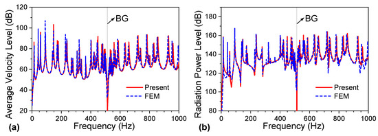
Figure 9.
(a) Average velocity level and (b) radiation power level of the water-loaded LR plate (BG: band-gap).
In order to illustrate the vibration and sound reduction performance of the water-loaded LR plate, the vibration and sound radiation results of both the LR plate and HM plate with water fluid are compared in Figure 10. As shown in Figure 3 and Figure 10, the band gaps calculated in an infinite periodic LR plate coincide with the response valleys of the vibration velocity and sound radiation power in a finite periodic plate. In the adjacent frequencies of the band gap (510.1–512.8 Hz), both the vibration and sound radiation of the LR plate are significantly reduced compared with the HM plate.
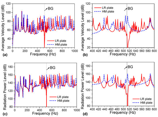
Figure 10.
Comparison of (a,b) average velocity level and (c,d) radiation power level between water-loaded locally resonant (LR) plate and water-loaded homogeneous (HM) plate (BG: band-gap).
The vibration and sound radiation of the LR plate with water fluid are also compared with the LR plate without fluid in Figure 11. The figure shows that the vibration and sound radiation can be reduced in a broad frequency range of 510.1~561.6 Hz for the unloaded LR plate. However, when the water fluid load is introduced, the vibration and sound radiation valleys’ bandwidth is significantly reduced to 510.1~512.8 Hz. This phenomenon is coincident with the band-gap property illustrated in Section 3.1. The comparison in Figure 11 indicates that an LR plate’s vibration and sound reduction performance in underwater surroundings is less efficient than in air due to the significantly reduced band-gap width.
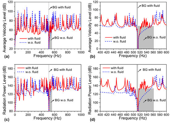
Figure 11.
Comparison of (a,b) average velocity level and (c,d) radiation power level between locally resonant (LR) plate with fluid and that without fluid (BG: band gap; w.o.: without).
The radiation efficiency of a water-loaded LR plate was also calculated using Equation (42) to further illustrate the vibration and acoustic coupling performance. The corresponding result is given in Figure 12, together with the result of a water-loaded HM plate for comparison purposes.
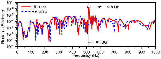
Figure 12.
Comparison of radiation efficiencies between a water-loaded locally resonant (LR) plate and a water-loaded homogeneous (HM) plate (BG: band gap).
As shown in Figure 12, in most of the frequency range, the radiation efficiency of the water-loaded LR plate and that of the water-loaded HM plate are of the same order in magnitude. However, in the frequency range of 513~525 Hz close above the band gap, the introduction of periodic resonators significantly increases radiation efficiency. In order to explain the mechanism behind the interesting and strange radiation phenomenon, the LR and HM plates’ normalized-displacement spatial distributions at 518 Hz are drawn in Figure 13.

Figure 13.
Spatial distributions of the normalized displacement (norm. disp.) at 518 Hz in (a) a homogeneous plate and (b) a locally resonant plate.
Figure 13a shows that the water-loaded HM plate’s vibrational spatial distribution at 518 Hz is dominated by the vibration mode of (2,5) order. As explained in the reference [46], this mode corresponds to a corner–radiation mode with less radiation efficiency than the edge–radiation and monopole–radiation modes. After the periodic resonators are attached, affected by the LR effect, the vibration mode at 518 Hz changes from the corner–radiation dominated mode to the monopole–radiation dominated mode, as shown in Figure 13b. In order to make it easier to be understood, the modal radiation efficiencies of mode (2, 5) and mode (1, 1) in the simply supported plate are given in Figure 14, which correspond to corner radiation and monopole radiation, respectively. As shown in the figure, below the coincidence frequency, the radiation efficiency of monopole radiation is much greater than that of the corner radiation, resulting in significantly increased radiation efficiency at the frequency close above the band gap.
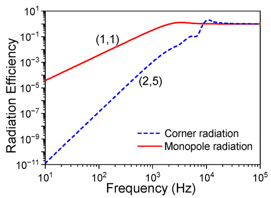
Figure 14.
Model radiation efficiencies of corner–radiation mode and monopole–radiation mode.
As can be seen in the above results, after water fluid is introduced to the LR plate, the vibrational and acoustic reduction performance worsens due to the reduced band-gap width induced by the attached fluid mass. Fortunately, the vibration and noise radiation can be further reduced by adding small damping on the resonators. The hysteretic damping with damping loss factor is added to the spring element of the resonator, with a complex stiffness expressed as . The average velocity and radiation power levels of a water-loaded HM plate and a water-loaded LR plate with lightly damped () and undamped periodic resonators are shown in Figure 15. The resonator’s damping parameter variation results are also given in Figure 16.
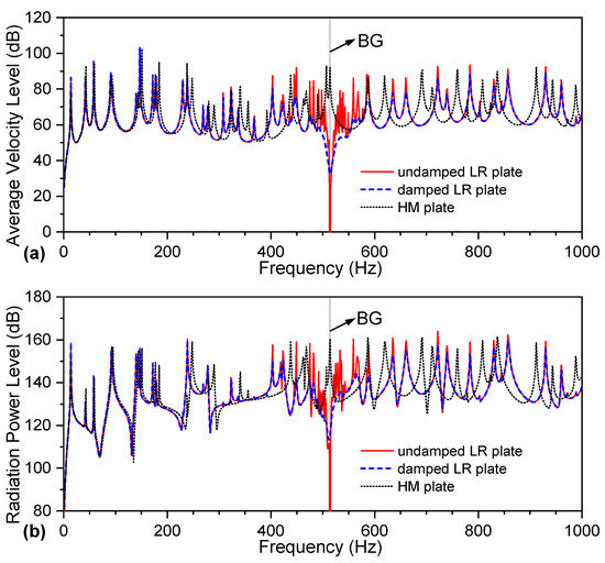
Figure 15.
(a) Average velocity level and (b) radiation power level of a water-loaded homogeneous (HM) plate and a water-loaded locally resonant (LR) plate with damped and undamped periodic resonators.
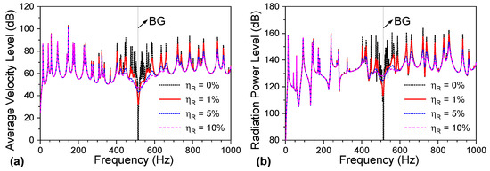
Figure 16.
(a) Average velocity level and (b) radiation power level of a water-loaded locally resonant plate with various damping parameters of the resonator.
As observed in Figure 15, for the lightly damped situation, the resonator’s damping had a minor effect on vibration and radiation below 440 Hz and above 600 Hz. As the resonator’s damping is introduced, the maximal attenuation level decreases in the band-gap frequency range. However, in the frequency range close above or below the band-gap, the vibration and sound radiation were significantly reduced compared with the undamped LR plate. As shown in Figure 16, with the increase in damping, the vibration and sound radiation became increasingly smaller above approximately 400 Hz, except in the band-gap frequency range. It can be concluded from the above analysis that, although the water-loaded LR plate’s band-gap width is relatively narrow with only several hertz, the attenuation zone of vibration and sound radiation can be broadened by adding damping into the resonator. This damping treatment makes the LR plate more beneficial for vibration or noise reduction in water-surrounding applications.
4. Conclusions
The vibro-acoustic performance of a water-loaded periodic locally resonant (LR) plate was studied in this research. The analytical models of the structure’s band gap, vibration, and acoustic radiation were theoretically derived with closed-form solutions, which helped to examine the effects of water fluid on the vibration and sound radiation of the LR structure and helped to clarify its effect mechanism.
The water fluid will introduce frequency-dependent attached mass on the LR plate, resulting in a significant increase of the effective density in the frequency range near the resonant frequency. Affected by the attached fluid mass, the upper band-gap frequency noticeably decreased, while the lower band-gap frequency stayed nearly unchanged, which lead to a significantly decreased band-gap width in a water-loaded LR plate. In addition, affected by the water fluid, the Bragg frequency is also decreased, resulting in the frequency range that can be tuned to control vibration and noise for the LR plate with the fluid being much narrower than that without the fluid. Furthermore, introducing periodic resonators significantly increases radiation efficiency close above the band-gap. This phenomenon is caused by the change of radiation mode from corner or edge radiation to monopole radiation.
The vibration and sound reduction performance of an LR plate covered with water fluid is inferior to that without fluid due to the extremely narrow band gap, which disadvantages the application in water surroundings. Fortunately, the vibration and sound radiation in the frequency range above or close below the band gap can be reduced by adding small damping into the resonators, inducing the attenuation zone to be significantly broadened. This damping treatment could be an efficient method to make the LR plate more beneficial for vibration or noise reduction in water-surrounding applications.
Author Contributions
Conceptualization, Z.G.; methodology, Z.G. and M.S.; software, Z.G.; validation, Z.G.; formal analysis, H.Z.; investigation, Z.G.; resources, M.S.; data curation, H.Z.; writing—original draft preparation, Z.G.; writing—review and editing, M.S., M.W. and H.Z.; visualization, Z.G. and Q.L.; supervision, M.S.; project administration, M.S.; funding acquisition, Z.G. and M.W. All authors have read and agreed to the published version of the manuscript.
Funding
This research was funded by the Ningbo Natural Science Foundation (grant number 2021J057), the Natural Science Foundation of Shannxi Province (grant number 2021JLM-39), and the Innovative Research Foundation of Ship General Performance (grant number 33122232).
Data Availability Statement
Not applicable.
Conflicts of Interest
The authors declare no conflict of interest.
References
- Gao, N.S.; Zhang, Z.C.; Deng, J.; Guo, X.Y.; Cheng, B.Z.; Hou, H. Acoustic metamaterials for noise reduction: A review. Adv. Mater. Technol. 2022, 7, 2100698. [Google Scholar] [CrossRef]
- Liao, G.X.; Luan, C.C.; Wang, Z.W.; Liu, J.P.; Yao, X.H.; Fu, J.Z. Acoustic metamaterials: A review of theories, structures, fabrication approaches, and applications. Adv. Mater. Technol. 2021, 6, 2000787. [Google Scholar] [CrossRef]
- Liu, J.Y.; Guo, H.B.; Wang, T. A review of acoustic metamaterials and phononic crystals. Crystals 2020, 10, 305. [Google Scholar] [CrossRef]
- Brillouin, L. Wave Propagation in Periodic Structures: Electric Filters and Crystal Lattices, 1st ed.; McGraw-Hill Book Company, Inc.: New York, NY, USA, 1946. [Google Scholar]
- Kushwaha, M.S.; Halevi, P.; Dobrzynski, L.; Djafarirouhani, B. Acoustic band-structure of periodic elastic composites. Phys. Rev. Lett. 1993, 71, 2022–2025. [Google Scholar] [CrossRef] [PubMed]
- Liu, Z.Y.; Zhang, X.X.; Mao, Y.W.; Zhu, Y.Y.; Yang, Z.Y.; Chan, C.T.; Sheng, P. Locally resonant sonic materials. Science 2000, 289, 1734–1736. [Google Scholar] [CrossRef]
- Wen, X.; Wen, J.; Yu, D.; Wang, G.; Liu, Y.; Han, X. Phononic Crystals, 1st ed.; National Defence Industry Press: Beijing, China, 2009. [Google Scholar]
- Wen, Q.H.; Zuo, S.G.; Wei, H. Locally resonant elastic wave band gaps in flexural vibration of multi-oscillators beam. Acta Phys. Sin. 2012, 61, 034301. [Google Scholar]
- Wu, J.; Bai, X.C.; Xiao, Y.; Geng, M.X.; Yu, D.L.; Wen, J.H. Low frequency band gaps and vibration reduction properties of a multi-frequency locally resonant phononic plate. Acta Phys. Sin. 2016, 65, 064602. [Google Scholar]
- Xiao, Y.; Wen, J.H.; Wen, X.S. Broadband locally resonant beams containing multiple periodic arrays of attached resonators. Phys. Lett. A 2012, 376, 1384–1390. [Google Scholar] [CrossRef]
- Romero-Garcia, V.; Krynkin, A.; Garcia-Raffi, L.M.; Umnova, O.; Sanchez-Perez, J.V. Multi-resonant scatterers in sonic crystals: Locally multi-resonant acoustic metamaterial. J. Sound Vib. 2013, 332, 184–198. [Google Scholar] [CrossRef]
- Xiao, Y.; Wen, J.H.; Wen, X.S. Sound transmission loss of metamaterial-based thin plates with multiple subwavelength arrays of attached resonators. J. Sound Vib. 2012, 331, 5408–5423. [Google Scholar] [CrossRef]
- Ma, J.G.; Sheng, M.P.; Guo, Z.W.; Qin, Q. Dynamic analysis of periodic vibration suppressors with multiple secondary oscillators. J. Sound Vib. 2018, 424, 94–111. [Google Scholar] [CrossRef]
- Qin, Q.; Sheng, M.P.; Guo, Z.W. Low-frequency vibration and radiation performance of a locally resonant plate attached with periodic multiple resonators. Appl. Sci. 2020, 10, 2843. [Google Scholar] [CrossRef]
- Guo, Z.; Guo, H.; Wang, T. Vibro-acoustic performance of acoustic metamaterial plate with periodic lateral local resonator. Acta Phys. Sin. 2021, 70, 214301. [Google Scholar] [CrossRef]
- Deymierv, P.A. Acoustic Metamaterials and Phononic Crystals; Springer Science & Business Media: New York, NY, USA, 2013. [Google Scholar]
- Spadoni, A.; Daraio, C.; Hurst, W.; Brown, M. Nonlinear phononic crystals based on chains of disks alternating with toroidal structures. Appl. Phys. Lett. 2011, 98, 161901. [Google Scholar] [CrossRef]
- Romeo, F.; Ruzzene, M. Wave Propagation in Linear and Nonlinear Periodic Media: Analysis and Applications; Springer Science & Business Media: New York, NY, USA, 2013. [Google Scholar]
- Fang, X.; Wen, J.H.; Benisty, H.; Yu, D.L. Ultrabroad acoustical limiting in nonlinear metamaterials due to adaptive-broadening band-gap effect. Phys. Rev. B 2020, 101, 104304. [Google Scholar] [CrossRef]
- Sheng, P.; Fang, X.; Wen, J.H.; Yu, D.L. Vibration properties and optimized design of a nonlinear acoustic metamaterial beam. J. Sound Vib. 2021, 492, 115739. [Google Scholar] [CrossRef]
- Duhamel, D.; Mace, B.R.; Brennan, M.J. Finite element analysis of the vibrations of waveguides and periodic structures. J. Sound Vib. 2006, 294, 205–220. [Google Scholar] [CrossRef]
- Mead, D.J. The forced vibration of one-dimensional multi-coupled periodic structures: An application to finite element analysis. J. Sound Vib. 2009, 319, 282–304. [Google Scholar] [CrossRef]
- Manktelow, K.; Narisetti, R.K.; Leamy, M.J.; Ruzzene, M. Finite-element based perturbation analysis of wave propagation in nonlinear periodic structures. Mech. Syst. Signal Process. 2013, 39, 32–46. [Google Scholar] [CrossRef]
- Qiu, C.Y.; Liu, Z.Y.; Mei, J.; Ke, M.Z. The layer multiple-scattering method for calculating transmission coefficients of 2D phononic crystals. Solid State Commun. 2005, 134, 765–770. [Google Scholar] [CrossRef]
- Wang, G.; Wen, J.H.; Wen, X.S. Quasi-one-dimensional phononic crystals studied using the improved lumped-mass method: Application to locally resonant beams with flexural wave band gap. Phys. Rev. B 2005, 71, 104302. [Google Scholar] [CrossRef]
- Cao, Y.J.; Hou, Z.L.; Liu, Y.Y. Finite difference time domain method for band-structure calculations of two-dimensional phononic crystals. Solid State Commun. 2004, 132, 539–543. [Google Scholar] [CrossRef]
- Li, C.; Chen, Z.; Jiao, Y. Vibration and bandgap behavior of sandwich pyramid lattice core plate with resonant rings. Materials 2023, 16, 2730. [Google Scholar] [CrossRef]
- Yu, D.L.; Liu, Y.Z.; Qiu, J.; Zhao, H.G.; Liu, Z.M. Experimental and theoretical research on the vibrational gaps in two-dimensional three-component composite thin plates. Chin. Phys. Lett. 2005, 22, 1958–1960. [Google Scholar]
- Zhao, H.G.; Wen, J.H.; Yu, D.L.; Wen, X.S. Low-frequency acoustic absorption of localized resonances: Experiment and theory. J. Appl. Phys. 2010, 107, 023519. [Google Scholar] [CrossRef]
- Meng, H.; Wen, J.H.; Zhao, H.G.; Wen, X.S. Optimization of locally resonant acoustic metamaterials on underwater sound absorption characteristics. J. Sound Vib. 2012, 331, 4406–4416. [Google Scholar] [CrossRef]
- Zhang, S.W.; Wu, J.H.; Hu, Z.P. Low-frequency locally resonant band-gaps in phononic crystal plates with periodic spiral resonators. J. Appl. Phys. 2013, 113, 163511. [Google Scholar] [CrossRef]
- Nouh, M.; Aldraihem, O.; Baz, A. Wave propagation in metamaterial plates with periodic local resonances. J. Sound Vib. 2015, 341, 53–73. [Google Scholar] [CrossRef]
- Hsu, J.C. Local resonances-induced low-frequency band gaps in two-dimensional phononic crystal slabs with periodic stepped resonators. J. Phys. D Appl. Phys. 2011, 44, 055401. [Google Scholar] [CrossRef]
- Xiao, Y.; Wen, J.H.; Yu, D.L.; Wen, X.S. Flexural wave propagation in beams with periodically attached vibration absorbers: Band-gap behavior and band formation mechanisms. J. Sound Vib. 2013, 332, 867–893. [Google Scholar] [CrossRef]
- Wang, Y.F.; Wang, Y.S. Complete bandgaps in two-dimensional phononic crystal slabs with resonators. J. Appl. Phys. 2013, 114, 043509. [Google Scholar] [CrossRef]
- Casadei, F.; Dozio, L.; Ruzzene, M.; Cunefare, K.A. Periodic shunted arrays for the control of noise radiation in an enclosure. J. Sound Vib. 2010, 329, 3632–3646. [Google Scholar] [CrossRef]
- Aladwani, A.; Almandeel, A.; Nouh, M. Fluid-structural coupling in metamaterial plates for vibration and noise mitigation in acoustic cavities. Int. J. Mech. Sci. 2019, 152, 151–166. [Google Scholar] [CrossRef]
- Claeys, C.C.; Sas, P.; Desmet, W. On the acoustic radiation efficiency of local resonance based stop band materials. J. Sound Vib. 2014, 333, 3203–3213. [Google Scholar] [CrossRef]
- Guo, Z.W.; Pan, J.; Sheng, M.P. Vibro-acoustic performance of a sandwich plate with periodically inserted resonators. Appl. Sci. 2019, 9, 3651. [Google Scholar] [CrossRef]
- Song, Y.B.; Wen, J.H.; Yu, D.L.; Liu, Y.Z.; Wen, X.S. Reduction of vibration and noise radiation of an underwater vehicle due to propeller forces using periodically layered isolators. J. Sound Vib. 2014, 333, 3031–3043. [Google Scholar] [CrossRef]
- Jin, G.Y.; Shi, K.K.; Ye, T.G.; Zhou, J.L.; Yin, Y.W. Sound absorption behaviors of metamaterials with periodic multi-resonator and voids in water. Appl. Acoust. 2020, 166, 107351. [Google Scholar] [CrossRef]
- Zhong, H.B.; Tian, Y.J.; Gao, N.S.; Lu, K.; Wu, J.H. Ultra-thin composite underwater honeycomb-type acoustic metamaterial with broadband sound insulation and high hydrostatic pressure resistance. Compos. Struct. 2021, 277, 114603. [Google Scholar] [CrossRef]
- Li, W.L. An analytical solution for the self- and mutual radiation resistances of a rectangular plate. J. Sound Vib. 2001, 245, 1–16. [Google Scholar] [CrossRef]
- Sugino, C.; Xia, Y.; Leadenham, S.; Ruzzene, M.; Erturk, A. A general theory for bandgap estimation in locally resonant metastructures. J. Sound Vib. 2017, 406, 104–123. [Google Scholar] [CrossRef]
- Xiao, Y.; Wen, J.H.; Wen, X.S. Flexural wave band gaps in locally resonant thin plates with periodically attached spring-mass resonators. J. Phys. D Appl. Phys. 2012, 45, 195401. [Google Scholar] [CrossRef]
- Fahy, F.; Gardonio, P. Sound and Structural Vibration: Radiation, Transmission and Response, 2nd ed.; Elsevier/Academic Press: Oxford, UK, 2007. [Google Scholar]
Disclaimer/Publisher’s Note: The statements, opinions and data contained in all publications are solely those of the individual author(s) and contributor(s) and not of MDPI and/or the editor(s). MDPI and/or the editor(s) disclaim responsibility for any injury to people or property resulting from any ideas, methods, instructions or products referred to in the content. |
© 2023 by the authors. Licensee MDPI, Basel, Switzerland. This article is an open access article distributed under the terms and conditions of the Creative Commons Attribution (CC BY) license (https://creativecommons.org/licenses/by/4.0/).