Abstract
This paper investigates the performance enhancements of permanent magnet Vernier machines (PMVMs) that can be achieved using a new structure of Halbach array permanent magnets (HAPMs) for a direct-drive motorcycle application. To start with, size and design specifications of the electric machine are determined based on the assumed acceleration and drive cycle performance of a motorcycle. Then, five-segment Halbach array permanent magnet Vernier machines (HAPMVMs) with two different slot/pole combinations (24 s/44 p and 12 s/20 p) are suggested and optimized to achieve a high torque density with an acceptable power factor while maintaining a low torque ripple. Two selected designs from optimizations are investigated in the full speed range considering power factor and efficiency maps. Consequently, in order to demonstrate the effectiveness of the proposed five-HAPM structure, the same optimization methods are repeated with three-segment HAPMs as well as with single-piece PMs. The comparisons show a great enhancement in torque and power factor achieved with the use of five HAPMs. For instance, for 22 s/44 p topology, generated torque doubles with the use of five-segment PMs compared to single-segment PMs. Finally, the harmonics of magnetic flux density in the airgap of PMVMs and HAPMVMs are compared and investigated to reveal the reasons behind the superiority of VMs with HAPMs.
1. Introduction
The recent trend in the design of traction systems for electric vehicles (EVs) is to decrease the volume and hence the total cost [1]. One common approach to achieve this is to increase the operation speed of electric machines. However, there are some challenges. Firstly, the maximum speed of the electric machine is limited, often due to mechanical and thermal constraints. Secondly, the need for a high gear ratio gear box increases the system complexity. If the required traction torque can be effectively generated in the available space of the wheel, direct drive machines are an excellent choice, with a reduced number of components. Direct drive machines can be especially considered for light EVs since these vehicles have a lower torque requirement and mostly a single wheel drive is sufficient for their traction.
Vernier machines (VMs) are known to have excellent torque densities due to their capability of generating high torque at low speeds by flux modulation through the stator teeth and rotor poles; this is called the magnetic gearing effect. Understanding flux modulation theory in electric machines and the relationship between VMs and magnetic gears is an important part of understanding VM’s operation, which is explained in [2,3,4]. VMs utilize multiple airgap harmonics to generate positive average torque through the special relation between number of stator slots and rotor poles [4,5].
Even though VMs can generate high torque at low speeds, their power factor (PF) reduces rapidly with the increase of stator current. Therefore, researchers come up with various topologies to achieve higher PF while maintaining the high torque density. The dual-stator/rotor topologies of VMs have attracted researchers’ attention because of their capability in generating higher torque and PF in comparison with single-rotor/stator VMs [6,7]. The proposed dual stator spoke-array VM in [8,9] demonstrates high-performance capabilities for EV applications. In [10], the authors propose a magnetless dual stator structure, where DC excitation windings are used instead of magnets to enhance performance. Ref. [10] also includes the hybrid excitation, which refers to the usage of both magnets and DC excitation windings for an outer rotor VM.
In [7], the authors report a PF of 0.89 with dual stator structure, in which the inner stator only includes magnets. This makes the structure complicated, and higher volume of magnets are required in comparison with single stator structures. Refs. [8,9] suggest a dual stator topology with spoke array magnets, while in [8], inner stator does not have any excitations, just slots, and in [9], there are excitation windings in both inner and outer stators. A PF of 0.9 is reported in [8] and one of 0.83 in [9]. A novel topology of dual rotor consequent pole VM is proposed in [11]. The authors present a comprehensive assessment of two structures of VMs with high-performance capabilities and comparison with conventional VMs in the literature. Based on the presented results, the maximum reached PF is 0.89 [11]. Therefore, it is concluded that dual stator/rotor topologies help to achieve a high PF, but the fabrication of such machines is complicated and costly.
Looking into the literature regarding single-rotor/stator structures, Prof. Lipo et al. published several papers and patents, in which they suggest a single-rotor/stator VM from a designed and manufactured double stator/single rotor topology. In these papers, the proposed VMs use 20 pole/12 slot configuration with the current density of 4.6 A/mm2 with single-rotor/stator topology [12,13,14]. Ref. [12] elucidates the details of modulation in VMs and proposes an analytical approach; the authors discuss the winding factors of the harmonics contributing to the torque generation and manage to calculate the back-EMF analytically. However, the analytical calculations of torque deviate from the FEA results. Moreover, ref. [12] reports a PF of 0.62 in the V-shape consequent pole structure with ferrite PMs, and [13] reports a PF of 0.83 in the V-shape structure with NdFeB PMs. Ref. [14] also proposes a V-shape consequent pole structure with NdFeB PMs, and the achieved PF is 0.58. Hence, it can be concluded that it is a challenge to reach high PF with a single rotor/stator structure.
Apart from the slot pole combinations and dual stator/rotor structures, the use of Halbach array permanent magnets is proposed by researchers. In [15], authors put Halbach array permanent magnets (HAPMs) in the stator slot openings. The results show an increase in both torque and power factor. However, putting magnets in both machine parts complicates the structure. In [16], two machines with Halbach array and concentrated windings are proposed but the obtained results do not demonstrate a significant advantage of the Halbach array topology. Ref. [17] also uses concentrated windings and puts Halbach array magnets in the stator and consequent pole magnets in the rotor. However, the model with Halbach array does not show a significant increase in torque density or power factor. Ref. [18] suggests a rather more complicated topology with two stators and a rotor, in which the inner stator winding is a DC-excited concentrated winding, and the rotor has HAPMs. The presented power factor (>0.9) and torque results are promising but come at the expense of a complicated structure. Moreover, torque ripple is more than 25%. Ref. [19] proposes an inner rotor Halbach array structure with 10 rotor poles and 6 stator slots and provides promising results with a power factor higher than 0.8 and a good torque density. However, the proposed magnet structure is rather complicated. In [20], the authors discuss the use of Halbach array magnets with three magnets on a dual rotor structure to enhance the power factor and torque density of the machine. A similar 27-slots-with-46-poles three-magnet HAPM with an outer rotor is analyzed in [21], and only the results for the torque and back-EMF are presented. However, the effect of using Halbach array on PF is not addressed and studied thoroughly.
Consequently, the Halbach array PM VMs (HAPMVMs) presented in the literature either have complicated structures or do not have significant performance improvements compared to conventional VMs. Moreover, only three magnet HAPMs have been considered so far.
VMs with five Halbach arrays are proposed as a novel configuration. Moreover, three Halbach arrays and single segments of PMs are optimized and investigated in detail for two different slot/pole combinations. Single rotor/stator topology structure is selected to simplify the mechanical structure and thermal management. This is of high importance for in-wheel or near-wheel drive applications. Consequent pole configuration is selected due to lower magnet volume, and simplified rotor structure as proposed in [12,13,14].
The presented results in this study clearly show the trade-offs between torque density and power factor for the selected slot/pole combinations and number of HAPM segments. The operation of proposed VMs is evaluated at various speeds, including the flux weakening region for a direct drive motorcycle application. Hence, the proposed structure paves the way for VMs to enter the traction applications which require variable speed and flux-weakening capabilities.
Hence, the contributions of this paper can be summarized as the demonstration of torque density and power factor enhancement utilizing HAPMs, the suggestion of a simpler single rotor/stator configuration to reach high performance (while dual rotor/stator are often proposed to reach high PF in the literature), and a comprehensive analysis and comparison of VMs for a light EV application.
2. Sizing of Electric Drive Based on Longitudinal Vehicle Dynamics Simulations
The design process is initiated with the longitudinal vehicle dynamics analysis to determine the required torque vs. speed characteristics of the electric machine. The maximum speed of the motorcycle is selected as 80 km/h and the acceleration time for 0–45 km/h is intended to be less than 7 s. This motorcycle is designed for urban transportation and is expected to operate in a slow and medium speed range of the world harmonized light-duty vehicles test procedure (WLTP1). This drive procedure is the most accepted drive cycle in the automobile industry.
Table 1 shows the mechanical features of the considered motorcycle. These are partially taken from [22], in which the frontal areas and drag coefficients of various motorcycles are calculated by numerical methods. By utilizing longitudinal vehicle dynamics equations and assumed vehicle characteristics, the performance of the vehicle is investigated. The findings and the decisions based on those findings are summarized below:

Table 1.
Motorcycle characteristics and calculated results from vehicle model.
- A maximum speed of 800 r/min for the electric machine is obtained;
- The vehicle needs at least 5.3 kW power to reach the maximum speed of 80 km/h (800 r/min) on a level ground. Therefore, the selected power rating of the electric machine is set to 5.5 kW;
- Calculations showed that starting torque of 150 N·m is required for the vehicle to achieve 0-45 km/h acceleration in under 7 s. By considering the power of 5.5 kW, the base speed is identified as 350 r/min.
Finally, the drive cycle performance of the vehicle is investigated using the forward simulation method [23]. Figure 1a displays the WLTP1 driving cycle and related torque and power points of the traction machine. As shown, the required torque is 65 N·m. The maximum torque requirement, 150 N·m, is 2.3 times this value, which means the vehicle is also suitable for uphill driving and more demanding drive cycles. The final torque-speed and power–speed characteristics of the traction machine can be also seen in Figure 1b.
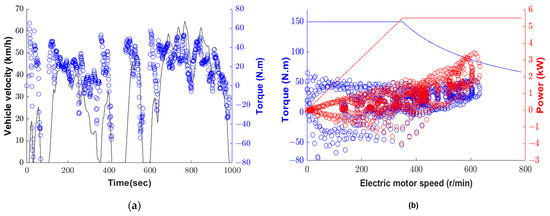
Figure 1.
Calculated operating points of the electric machine for WLTP1 driving cycle: (a) driving cycle and torque points of the traction machine; (b) torque/power vs. electric motor speed and operating points.
At this point, it is important to comment on the suitability of the direct drive traction for a light electric vehicle application. Based on the assumed vehicle characteristics, 150 N·m is found as the maximum required torque. This value starts from around 2000 N·m, which is the total tractive torque, for battery-electric passenger vehicles. This shows that light electric vehicles, especially when they are driven from a single wheel, are highly suitable for direct drive configuration.
3. Theory Framework
VMs can generate high torque at low speeds, utilizing the modulation effect caused by permeance harmonics of the stator slots and rotor poles. In fact, the airgap flux is modulated through the stator and rotor poles, which eventually creates a higher average torque and back EMF. VMs can be regarded as a synchronous machine integrated with a magnetic gear [24,25]. Their operation can be explained from the point of view of coaxial magnetic gears.
A conventional coaxial magnetic gear consists of three parts: the inner rotor, the modulating ring (segments), and the outer rotor. The modulating ring consists of ferromagnetic segments that are sandwiched between the two rotors. The inner and outer rotors both hold sets of PMs. When one rotor is driven by a force while the modulating ring is stationary, the other rotor will rotate in the opposite direction. A special relationship between the number of outer and inner pole pairs and the number of ferromagnetic segments is required. This is as follows:
where is the number of ferromagnetic segments on the modulating ring and and are the number of PM pole pairs on the inner and outer rotors, respectively.
VMs are obtained by simplifying the coaxial magnetic gear structure from having two rotors and one stator to one rotor and one stator. The high-speed rotor of coaxial magnetic gear is replaced with multi-phase windings and segments with stator poles while using the same low-speed rotor. Therefore, a rotation with lower speed than the synchronous speed of the fundamental rotating magnetic field can be generated. Consequently, the performance of a VM depends on the slots/poles combination and number of phases and there must be a special relationship with the number of rotor/stator poles as derived in [13,14] and given as:
where is the number of stator poles, is the number of stator slots, and is the number of rotor poles. In a balanced integer slot three-phase machine, the number of stator slots should be a multiple of the stator poles and phases such as = 3, where is the slot/pole/phase. Hence, (2) can be rewritten as:
By taking in (3) for a four-pole machine (), the number of rotor poles will be or 28. Similarly, by taking for a four-pole machine (), the number of rotor poles will be or 52. It is shown in [13,14] that the minus value in (3) creates a higher equivalent winding factor and consequently a higher back EMF and torque. Hence, by taking only minus operations in (3), the resultant numbers of poles are 12 slots/20 poles and 24 slots/44 poles [13,14]. These slot/pole combinations are assumed in this study. The 24 slots/44 poles designs are called model A and 12 slots/20 poles designs are called model B.
The ratio is defined as a gear ratio. A higher gear ratio will generate more back EMF and torque. However, a higher gear ratio causes a high inductance and, as a result, the power factor significantly drops after a certain value of input current. The values of gear ratio are 11 and 5 for model A and model B, respectively. Gear ratio values show that model A is expected to have a better torque generating capability, but lower power factor compared to model B. Furthermore, model B has a simpler structure than model A.
Analytical calculation of the performance (back-EMF and torque) parameters of a VM is complicated because in addition to the fundamental component, harmonics contribute to torque generation. The analytical calculations presented in [12] achieve good accuracy for back-EMF calculation for the consequent pole magnet structure. However, the torque analytical results deviate from FEA results. Moreover, in all papers, torque ripple calculation relies on FEA.
Hence, to consider the effect of geometry of stator, rotor and the proposed Halbach array magnets on the performance of the VM with respect to torque, torque ripple, and power factor, a detailed investigation/optimization using finite element analysis (FEA) is crucial. Moreover, one of the goals of this study is to investigate limits of the power factor for each slot/pole combination.
4. Initial Design and Optimization of the VMs with Five-Segment Halbach Array PMs
This section proposes a new configuration of the Halbach array with five-segment PMs to increase the torque density and PF, which is shown in Figure 2 for two slot pole combinations (24 s/44 p and 12 s/20 p).
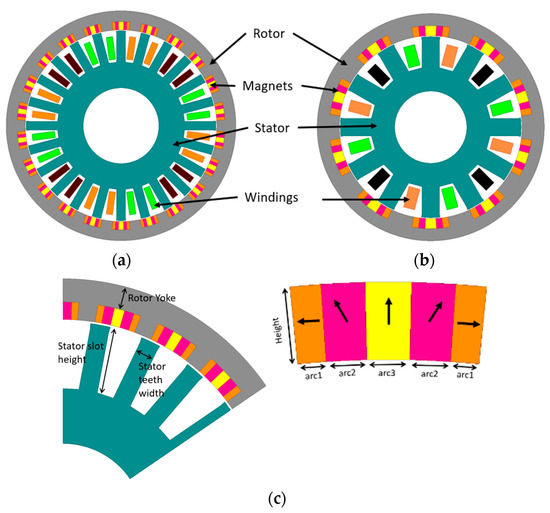
Figure 2.
Proposed HAPMVMs and geometry variables: (a) Initial Model A5: 24 slots, 44 poles; (b) Initial Model B5: 12 slots, 20 poles; (c) optimization variables and magnetization direction of magnets.
Due to the lack of a comprehensive sizing method for VMs in the literature, this paper decides on the outer diameter of the machine based on the available space inside the wheel. Since the wheel diameter of the motorcycle is assumed to be 270 mm and there is going to be a tire casing and housing around the motor, the outer diameter of 180 mm is chosen for the machine.
In this paper, the authors try to demonstrate important aspects in the design of VMs with comparisons between various HAVMs with two slot/pole combinations. Consequently, two HAPMVMs with an outer diameter of 180 mm, peak torque of 150 N·m, peak power of 5.5 kW, and a maximum speed of 800 r/min are designed.
The optimization results of 5-segment HAPMVM models, called A5 and B5 HAPMVMs, are presented in this section. Model A5 has 44 poles, or 22 consequent poles, and model B5 has 20 poles, or 10 consequent poles. In the first part, the torque and PF of output designs from optimizations are presented to identify the performance limits of each slot and pole combination. Then, comparisons and discussions related to the capabilities of each model, including the torque speed curve and efficiency maps of selected designs, are included in the second part.
4.1. Optimization of A5 and B5 HAPMVMs
The two initial models of A5 and B5 are shown in Figure 2a,b, and Table 2 summarizes their initial design parameters including the used material characteristics. The initial stack length of machines is set to 70 mm, but the stack length of each machine is then adjusted to reach the required peak torque after the optimization process. As the system is naturally cooled, the peak current density is assumed to be 7 A/mm2, which is associated with 150 N·m for several seconds. A typical fill factor of 45% for round wires is assumed. The battery DC link voltage is taken as 48 V.
Table 2.
Initial design parameters of A5 and B5 HAPMVMs.
The optimization variables are shown in Figure 2c. There are in total seven optimization variables. The two optimization objectives for both models are as follows:
- Maximizing the average torque;
- Maximizing the power factor.
Moreover, a torque ripple percentage less than 10% is sought. This arrangement for torque ripple makes sure that the cogging torque is kept in an acceptable range. Plus, peak to peak cogging torque values are presented in Table 3. This is mainly included for B5 HAPMVM as 12 slots/20 poles VMs are known to have a higher torque ripple than other types [14].
Table 3.
Optimized design variables of VMs and output results.
A single objective genetic algorithm is utilized as the optimization algorithm. The cost function is defined as the sum of the normalized weighted values of individual objectives. Hence, to assess the capability of A5 and B5 HAPMVMs regarding the torque and PF, three distinct optimizations are performed with three different weights for average torque, power factor, and torque ripple. The considered weights are (10; 1; 1), (1; 1; 1), and (1; 10; 1) with respect, Torque weight; PF weight; and Torque ripple weight. It is seen that by putting more weight to the torque sub-objective function, the optimization tries to reach the maximum possible torque, which results in lower power factor. Alternatively, putting more weight to the power factor sub-objective function, the optimization tries to reach high PF which results in lower torque values.
It should be noted that the VMs are excited only by q-axis current similar to surface-mounted permanent magnet machine. The phase advance (current angle) can later be utilized to increase the power factor at the cost of a lower average torque, which is not considered in this study.
The optimization results are presented in Figure 3 and Figure 4 for A5 and B5 designs. As expected, A5 HAPMVM can reach higher torque while B5 can reach higher PF. A5 HAPMVM can be designed to reach 180 N·m with a power factor of around 0.55 or to reach a power factor of 0.7 with a torque output of 120 N·m, whereas B5 HAPMVM can be designed to reach 120 N·m with a power factor of around 0.75 or to reach a power factor of 0.9 with a torque output of 80 N·m.
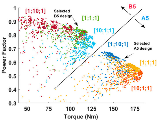
Figure 3.
The optimization results for A5 and B5 HAPMVMs with three different weights for average torque, power factor, and torque ripple, respectively.
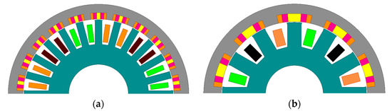
Figure 4.
Selected A5 and B5 designs from optimization results: (a) selected A5 design; (b) selected B5 design.
After investigating optimization results, an A5 design with a reasonable PF that is 0.61 and a torque output of 160 N·m, and a B5 design with a high PF that is 0.85 and also near the maximum possible torque, are selected for detailed analysis. These selected designs are marked in Figure 3 and exact geometries are shown in Figure 4.
The stack length of both designs is adjusted to meet the requirement of 150 N·m torque at 7 A/mm2 current density, in which the A5 design stack length decreased to 65 mm, but the stack length of B5 design increased to 100 mm. Variables and obtained results of the selected designs are summarized in Table 3.
It is clear that the B5 design needs more magnet and core material to reach the specified torque constraint. The torque per magnet volume (TPMV) that shows the relation between generated average torque and magnet volume is 53% higher in A5 design. Additionally, the total volume of A5 design is 54% lower than total volume of B5 design. These comparisons also indicate the lower total cost of A5 design. Plus, the efficiency of B5 design is slightly better than A5 design due to its lower core loss at 300 r/min.
The only drawback of A5 design is its poor power factor (PF), which is 0.61 for a current density of 7 A/mm2. Although the drawback of most VMs is their low PF at high current densities, the PF of model B5 at a similar current density is 0.85. Furthermore, by utilizing a phase advance of 10 electrical degrees, the PF can be increased to 0.91 while keeping the output torque. It should be mentioned that such a high PF has not been reported in VM with a single rotor and single stator structure in the literature. So, this feature of model B5 is a privilege from a PF point of view.
The harmonics of the airgap are displayed in Figure 5a. A5 design utilizes 1st, 11th, and 23rd harmonics to generate positive torque, while B5 design utilizes 1st, 5th, and 11th harmonics. Moreover, from the harmonic spectrum, it can be inferred that B5 design has a higher harmonic content in the airgap, which results in higher torque ripples. The torque outputs and power factors of selected designs at various operating current densities are compared in Figure 5b. The results show that PFs of both A5 and B5 designs are better at lower current densities. Plus, A5 design has an acceptable PF (>0.8) up to A/mm2, where a torque of 105 N·m can be reached, and this torque value is sufficient for most of the driving experiences, as shown in Figure 1.
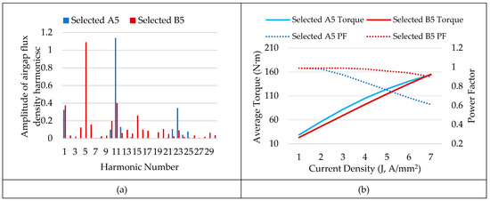
Figure 5.
(a) Harmonics of the airgap flux density; (b) performance parameters of selected A5 and B5 designs.
4.2. Operation of the Selected HAPMVMs at Full Speed Range including Flux Weakening Region
Considering several points is not sufficient to compare efficiencies and also to understand the effect of the low power factor on the inverter sizing. Thus, efficiency and power factor maps of the selected designs are investigated in the full speed range. The performance investigation of VMs in a wide speed range has not been addressed sufficiently in the literature. Hence, the results of this section are beneficial for evaluating the pros and cons of VMs in traction applications. The efficiency and power factor results are given in Figure 6.
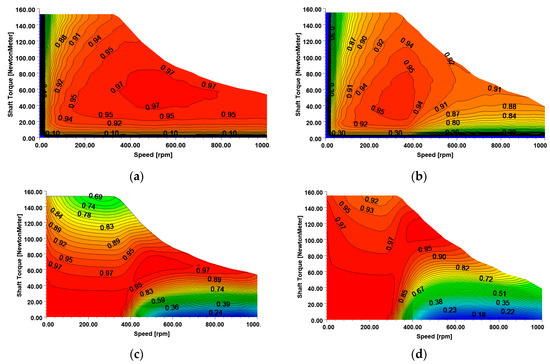
Figure 6.
Performance of selected designs in a wide speed range (including constant torque and constant power regions): (a) efficiency map of A5 design; (b) efficiency map of B5 design; (c) power factor map of A5 design; (d) power factor map of B5 design.
Efficiency is calculated only by considering the cooper and core losses. The other types of losses, such as windage, bearing, and PM losses, are ignored due to low rotational speed. It can be noted that A5 design has a higher efficiency value than B5 design for variable speed operation. However, the PF of A5 design is lower than B5 design in high torque regions around base speed.
After inspecting the operating points in WLTP1 5, operating points at 50 N·m torque with rotational speeds changing between 100–600 r/min with 100 r/min steps and 5 operating points at 25 N·m torque at the same speeds are averaged to compare the average efficiencies of the designs. These results are summarized in Table 4. A5 design is found to have higher average efficiencies in both cases.
Table 4.
Average efficiency and apparent power comparison.
To compare the inverter power ratings, the maximum required apparent input power values at 5.5 kW output at base and maximum speeds are calculated and listed in Table 4. As seen, A5 design’s maximum apparent power is 8.4 kVA, which occurs at base speed, and B5 design’s is 7.1 kVA, which occurs are maximum speed. Due to the lower PF of A5 design, the power rating of inverter for A5 design is required to be 18% higher than that of B5 design. Hence, the size and cost of the required inverter for A5 design is expected to be higher approximately with this percentage, too. However, the machine and total permanent magnet volumes of A5 design are 65% and 53% of the values of B5 design, respectively.
By comparing the specific power densities of inverters and electric machines reported in [1], the specific power density of the inverter can be assumed to be higher than that of electric machine. Even if the selected VMs have a very high torque density, their power densities are lower than the machines with a high speed given in the reference. Therefore, a drive system that uses A5 design is expected to be smaller in volume and weight. The cost of the drive systems is harder to compare due to the fluctuations in raw material prices. Therefore, we would like to make some rough comments. The drive systems of A5 needs an 18% bigger inverter but A5 design’s volume is 65% of the B5 design. Both drive systems are expected to have very close raw material prices if inverter cost per kVA is equal to twice the electric machine’s cost per kVA when B5 design is taken as reference.
5. Comparison of Single Segment PM, 3 Segment HAPM and 5 Segment HAPM VMs in Torque and Power Factor
One of the motivations of this study is to identify the influence of the number of Halbach array permanent magnet segments on the machine characteristics. So far, consequent pole five segment HAPMVMs are optimized and compared. However, manufacturing becomes more complex as the number of permanent magnet segments increases. Thus, it is important to show the effect of permanent magnet segments on machine characteristics and, accordingly, to decide on the number of permanent magnet segments.
To achieve this, four new models, which are shown in Figure 7a–d, are prepared. Models with three-segment permanent magnets are called A3 and B3, and models with single-segment permanent magnets are called A1 and B1. The related magnetization directions are displayed on the related figures. As can be seen, A1 and B1 models are regular consequent pole PMVMs. Model A3 with 24 slots and 44 poles was proposed in [20], with a double rotor topology. Model A1 with 24 slots and 44 poles was proposed in [11], with a double rotor topology. Hence, those four models are redesigned with an outer rotor structure to have a fair comparison with the proposed VMs. The same design constraints and optimization steps applied to five segment permanent magnet models are repeated for these models, as well.
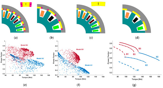
Figure 7.
The typical VMs from literature with one outer rotor and related optimizations results: (a) model A3 [20] (24–44 poles); (b) model B3 [20] (12–20 poles); (c) model A1 [11] (24–44 poles); (d) model B1 [11] (12–20 poles); (e) optimization results for A3 and B3 HAPMVMs; (f) optimization results for A1 and B1 VMs; (g) torque and PF trend lines of all the studied VMs.
Figure 7e,f demonstrates the optimization results for A1 and B1, and A3 and B3 HAPMVMs. The expected trend that A type designs can reach a higher torque but with a lower power factor compared to B type designs is observed.
Figure 7g summarizes torque and PF limit performance lines of all the studied VMs. It can be inferred that the segmentation of magnets and the utilization of different magnetization directions significantly improves the torque and PF of the VMs. On the other hand, it is interesting to see how the distribution of possible machine characteristics changes. The results can be summarized as:
- For A type VMs, the maximum achievable torque improves by 20% and 47% when the number of segments increased to three and five with respect to single-segment designs. Moreover, a maximum PF of 0.71 can be achieved with 131 N·m torque output;
- For B type VMs, the maximum achievable torque improves by 22% and 32% when the number of segments increased to three and five with respect to single-segment designs. Moreover, a maximum PF of 0.92 can be achieved with 84 N·m torque output;
- For A type PMs, the increase of torque and PF is so significant that the implementation of the five magnet structure pays off. However, there is a lower improvement between B3 and B5 designs.
6. A Deeper Dive into the Effect of Utilizing Five Magnet Structure in VMs
Furthermore, to look deeper into the effect of Halbach array magnets, a comparison is also conducted between the five-magnet Halbach array topology and its single-magnet counterpart. To do that, the selected A5 and B5 designs in Section 4 are changed into a single magnet configuration while maintaining all the variables identical. The models that are yielded from selected A5 and B5 designs and only have a single-segment magnet are called A51 design and B51 design, respectively. Hence, the only difference between A5 design and A51 design is the magnetization direction of the magnets.
The FEA results for output values of all four designs are presented in Table 5. The reduction of permanent magnet segments to one causes a high decrease in torque values—around a 40% decrease between A designs and around a 30% decrease in B designs. A decrease in power factor values is also observed. Moreover, core losses of single-segment magnet designs are halved compared to five-segment designs. It is important to mention that A51 and B51 designs are not optimized and are only generated to show the effects of the Halbach array configuration. The achievable torque and power factor with a single segment design is limited. Moreover, the high torque ripple value of B51 design should be disregarded because A51 and B51 design are not optimized.
Table 5.
Comparison of Halbach array magnet and single magnet structures.
Torque, power factor, and core loss results suggest a big difference in the magnetic flux density distributions of the designs with five and single-segment PMs. Therefore, magnetic flux density distributions of the machines are analyzed. Figure 8a–d shows the magnetic flux path of designs A5, B5, A51, and B51 at no load. It can be easily observed that A51 and B51 designs have a higher rotor flux leakage and a much lower fundamental flux in the stator back iron. To quantify this effect, airgap flux density harmonics of A5 and A51 designs are shown in Figure 8e, and B5 and B51 designs in Figure 8f. The fundamental airgap harmonics are almost halved in designs with one PM segment. Another torque producing harmonic, the 11th harmonic in A51, is around 71% of the value of A5, and the 5th harmonic in B51 is around 78% of the value of B5. These comparisons clearly show the reason behind the higher torque output and power factor values of VMs with HAPMs.
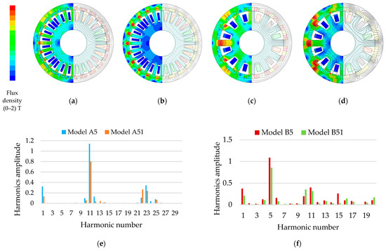
Figure 8.
Flux path and flux density of Halbach array (A5, B5) and single magnet counterpart (A51, B51) designs at open circuit (a–d) and their airgap flux density harmonics (e,f). (a) A5 design; (b) A51 design; (c) B5 design; (d) B51 design; (e) harmonics of airgap flux density for A5 and A51 designs, dominant working harmonics to generate positive torque are 1st, 11th and 23rd; (f) harmonics of airgap flux density for B5 and B51 designs; the dominant working harmonics to generate positive torque are 1st, 5th, and 11th.
The reported results confirm that VMs are promising candidates for direct drive applications and the capabilities of such machines can be further improved with the use of HAPMs.
7. Summary
A comprehensive design study of a direct drive traction machine for a light electric vehicle is presented in this study. VMs with a single stator and a single outer rotor that consist of consequent-pole Halbach array permanent magnets are evaluated based on their torque outputs, power factor values, and input power ratings.
Firstly, the required electric machine ratings are calculated with the help of the implemented vehicle model. For a motorcycle with a maximum speed of 80 km/h and 0–45 km/h acceleration in less than 7 s, 5.5 kW peak power and 150 N·m peak torque requirements were calculated. Drive cycle simulations carried out for WLTP1 show the operating points of the electric machine and validate the derivability of the vehicle.
Secondly, HAVMPMs with five-segment PMs were proposed and optimized. The proposed five-segment HAPMVMs were not mentioned in the literature. Two slot/pole combinations that are 24 slots/44 poles (model A) and 12 slots/20 poles (model B) were selected to show the trade-offs between the torque density and power factor. Investigation of the optimization results revealed that A5 HAPMVMs have higher torque density while B5 HAPMVMs have higher power factor. Two machines (selected A5 and B5 designs) were optimized to reach the peak torque requirement of 150 N·m based on the motorcycle application. The results showed that the selected A5 design can reach such torque with 1.65-L machine active volume, which means that A5 models offer higher torque density and significant cost reduction compared to the selected B5 design with 2.54-L machine active volume. It was noted that the selected A5 design has 50% less magnet volume. The PF of the selected A5 and B5 designs are 0.61 and 0.85 at a current density of 7 A/mm2, respectively. Though the results reveal that A5 design has a lower PF, PF drop happens in torques higher than 105 N·m, while the continuous torque is 65 N·m. Afterwards, the selected A5 and B5 designs were analyzed in the whole speed range. The torque vs. speed curves show that the proposed VMs can operate up to three times its base speed. Furthermore, the input apparent power requirements of both designs are compared considering the whole operation range by using the power factor and efficiency maps. It is found that the drive system of A5 design needs an inverter with 18% bigger ratings. So, A5 design is an acceptable design considering the 50% reduction in machine total active volume, even though it requires a bigger inverter.
To compare the proposed model A5 and model B5 with the literature, model A and model B are re-optimized with three-segment HAPMs and also with single-segment PMs. All the optimization results are compared, and the performance increase due to the use of HAPMs are clearly shown. Each slot/pole combination benefits from Halbach array PMs differently. When single-segment and five-segment designs are compared, Model A’s torque density is doubled and its power factor increases above 0.6, whereas model B’s torque density increases only by 50% and its power factor increases by 10%. This shows that the number of HAPM segments must be decided for each slot/pole combination differently, and the use of HAPMs pays off for the A model which has 24 slots/44 poles.
Finally, the effects of HAPMs on the magnetic field of VMs are shown, and the reasons behind the increase in torque and power factor are identified as the decrease in the rotor leakage flux and the increase in the torque-producing airgap flux harmonics.
The presented results clearly show the benefits of the use of the HAPMVMs in light electric vehicles with direct drive. Moreover, torque and power factor limitations of HAPMVMs with different slot/pole combinations and the number of HAPM segments are comparatively presented.
Moreover, even though there are challenges in the manufacture of such Halbach arrangements, three-segment HAVMs are manufactured in [26] and HAs with four-segment structure are manufactured in [27] for a linear VM. Hence, with careful design, the manufacture of five-segment HA is also possible.
8. Conclusions
The results of this research demonstrated that a considerably high torque density and acceptable PF can be reached in VMs with a single outer rotor and inner stator structure with utilizing the proposed Halbach array PMs. It was shown that with the usage of HAPMs, the vernier machine size can be reduced by around 50–70% (comparing single-segment to five-segment PMs), which is a considerable advantage for VMs. Moreover, it was found that selected slot/pole combinations highly affect torque density and PF. Hence, this selection should be conducted carefully. Moreover, the structure of the magnet segments and magnetization directions of magnets have considerable effects on the torque density and/or PF.
It should be mentioned that the proposed configurations of model A and model B have 22 and 10 consequent pole PMs, respectively. Hence, from the perspective of the number of magnets, these machines are simple. Furthermore, the mechanical structure of the proposed VMs is reasonable due to the existence of only one rotor/stator.
Furthermore, since one important objective of this research was to carefully select the slot/pole combination, future works can be directed toward inspecting the capabilities of other slot/pole combinations. In addition, research regarding the manufacture of the five-magnet structure could add considerable value to the ongoing research on vernier machines.
Author Contributions
Conceptualization, A.A.; methodology, A.A. and E.B.; validation, A.A. and E.B. and A.M.; formal analysis, A.A.; investigation, A.A.; resources, A.A. and E.B.; data curation, A.A. and E.B.; writing—original draft preparation, A.A.; writing—review and editing, A.A. and E.B and AM; visualization, A.A. and E.B.; supervision, E.B. and A.M. All authors have read and agreed to the published version of the manuscript.
Funding
This research received no external funding.
Data Availability Statement
Not applicable.
Conflicts of Interest
The authors declare no conflict of interest.
References
- Husain, I.; Ozpineci, B.; Islam, S.; Gurpinar, E.; Su, G.-J.; Yu, W.; Chowdhury, S.; Xue, L.; Rahman, D.; Sahu, R. Electric Drive Technology Trends, Challenges, and Opportunities for Future Electric Vehicles. Proc. IEEE 2021, 109, 1039–1059. [Google Scholar] [CrossRef]
- Cheng, M.; Han, P.; Hua, W. General Airgap Field Modulation Theory for Electrical Machines. IEEE Trans. Ind. Electron. 2017, 64, 6063–6074. [Google Scholar] [CrossRef]
- Qu, R.; Li, D.; Wang, J. Relationship between magnetic gears and vernier machines. In Proceedings of the 2011 International Conference on Electrical Machines and Systems, Beijing, China, 20–23 August 2011; pp. 1–6. [Google Scholar]
- Zou, T.; Li, D.; Chen, C.; Qu, R.; Jiang, D. A Multiple Working Harmonic PM Vernier Machine with Enhanced Flux-Modulation Effect. IEEE Trans. Magn. 2018, 54, 8109605. [Google Scholar] [CrossRef]
- Zou, T.; Li, D.; Qu, R.; Jiang, D.; Li, J. Advanced High Torque Density PM Vernier Machine with Multiple Working Har-monics. IEEE Trans. Ind. Appl. 2017, 53, 5295–5304. [Google Scholar] [CrossRef]
- Yu, J.; Liu, C.; Zhao, H. Design and Multi-Mode Operation of Double-Stator Toroidal-Winding PM Vernier Machine for Wind-Photovoltaic Hybrid Generation System. IEEE Trans. Magn. 2019, 55, 8700107. [Google Scholar] [CrossRef]
- Baloch, N.; Kwon, B.-I.; Gao, Y. Low-Cost High-Torque-Density Dual-Stator Consequent-Pole Permanent Magnet Vernier Machine. IEEE Trans. Magn. 2018, 54, 8206105. [Google Scholar] [CrossRef]
- Kwon, J.-W.; Kwon, B.-I. Investigation of Dual-Stator Spoke-Type Vernier Machine for EV Application. IEEE Trans. Magn. 2018, 54, 8206505. [Google Scholar] [CrossRef]
- Li, D.; Qu, R.; Lipo, T.A. High-Power-Factor Vernier Permanent-Magnet Machines. IEEE Trans. Ind. Appl. 2014, 50, 3664–3674. [Google Scholar] [CrossRef]
- Yu, J.; Liu, C. Design of a Double-Stator Magnetless Vernier Machine for Direct-Drive Robotics. IEEE Trans. Magn. 2018, 54, 8105805. [Google Scholar] [CrossRef]
- Allahyari, A.; Torkaman, H. A Novel High-Performance Consequent Pole Dual Rotor Permanent Magnet Vernier Machine. IEEE Trans. Energy Convers. 2020, 35, 1238–1246. [Google Scholar] [CrossRef]
- Liu, W.; Lipo, T.A. Analysis of Consequent Pole Spoke Type Vernier Permanent Magnet Machine with Alternating Flux Barrier Design. IEEE Trans. Ind. Appl. 2018, 54, 5918–5929. [Google Scholar] [CrossRef]
- Liu, W.; Lipo, T.A. A family of vernier permanent magnet machines utilizing an alternative rotor leakage flux blocking design. In Proceedings of the 2017 IEEE Energy Conversion Congress and Exposition (ECCE), Cincinnati, OH, USA, 1–5 October 2017; pp. 2461–2468. [Google Scholar]
- Liu, W.; Wang, J.; Lipo, T.A. A Consequent Pole Single Rotor Single Stator Vernier Design to Effectively Improve Torque Density of an Industrial PM Drive. IEEE Trans. Ind. Electron. 2023, 70, 255–264. [Google Scholar] [CrossRef]
- Xie, K.; Li, D.; Qu, R.; Gao, Y. A Novel Permanent Magnet Vernier Machine with Halbach Array Magnets in Stator Slot Opening. IEEE Trans. Magn. 2017, 53, 7207005. [Google Scholar] [CrossRef]
- Xu, L.; Liu, G.; Zhao, W.; Ji, J.; Fan, X. High-Performance Fault Tolerant Halbach Permanent Magnet Vernier Machines for Safety-Critical Applications. IEEE Trans. Magn. 2016, 52, 8104704. [Google Scholar] [CrossRef]
- Adnani, K.; Shafiei, S.; Millimonfared, J.; Moghani, J.S. Modified Unipolar Hybrid Permanent Magnet Vernier Machine Using Halbach Array Configuration. In Proceedings of the 2019 10th International Power Electronics, Drive Systems and Technologies Conference (PEDSTC), Shiraz, Iran, 12–14 February 2019; pp. 40–43. [Google Scholar] [CrossRef]
- Wei, L.; Nakamura, T. A Novel Dual-Stator Hybrid Excited Permanent Magnet Vernier Machine with Halbach-Array PMs. IEEE Trans. Magn. 2021, 57, 8101705. [Google Scholar] [CrossRef]
- Kataoka, Y.; Takayama, M.; Matsushima, Y.; Anazawa, Y. Design of surface permanent magnet-type vernier motor using Halbach array magnet. In Proceedings of the 18th International Conference on Electrical Machines and Systems (ICEMS), Pattaya, Thailand, 25–28 October 2015; pp. 177–183. [Google Scholar] [CrossRef]
- Allahyari, A.; Mahmoudi, A.; Kahourzade, S. High Power Factor Dual-Rotor Halbach Array Permanent-Magnet Vernier Machine. In Proceedings of the 2020 IEEE International Conference on Power Electronics, Drives and Energy Systems (PEDES), Jaipur, India, 16–19 December 2020; pp. 1–6. [Google Scholar] [CrossRef]
- Chen, Q.; Fan, Y.; Lei, Y.; Wang, X. Multiobjective Optimization Design of Unequal Halbach Array Permanent Magnet Vernier Motor Based on Optimization Algorithm. IEEE Trans. Ind. Appl. 2022, 58, 6014–6023. [Google Scholar] [CrossRef]
- Selvamuthu, T.; Thangadurai, M. Motorcycle Drag Reduction using a Streamlined Object Ahead of the Rider. J. Inst. Eng. (India) Ser. C 2019, 100, 801–810. [Google Scholar] [CrossRef]
- Larminie, J.; Lowey, J. Electric Vehicle Technology Explained; J. Wiley: West Sussex, UK, 2012; Chapter 8; pp. 187–216. [Google Scholar]
- Fu, W.N.; Liu, Y. A unified theory of flux-modulated electric machines. In Proceedings of the 2016 International Symposium on Electrical Engineering (ISEE), Hong Kong, China, 14 December 2016; pp. 1–13. [Google Scholar] [CrossRef]
- Li, D.; Qu, R.; Li, J. Topologies and analysis of flux-modulation machines. In Proceedings of the 2015 IEEE Energy Conversion Congress and Exposition (ECCE), Montreal, QC, Canada, 20–24 September 2015; pp. 2153–2160. [Google Scholar]
- Chen, Q.; Fan, Y.; Lei, Y.; Wang, X. Multi Objective Optimization Design of Unequal Halbach Array Permanent Magnet Vernier Motor Based on Optimization Algorithm. In Proceedings of the 2021 IEEE Energy Conversion Congress and Exposition (ECCE), Vancouver, BC, Canada, 10–14 October 2021; pp. 4220–4225. [Google Scholar] [CrossRef]
- Zhou, Y.; Qu, R.; Li, D.; Gao, Y.; Lee, C.H.T. Performance Investigation and Improvement of Linear Vernier Permanent Magnet Motor for Servo Application. IEEE/ASME Trans. Mechatron. 2023, 1–13. [Google Scholar] [CrossRef]
Disclaimer/Publisher’s Note: The statements, opinions and data contained in all publications are solely those of the individual author(s) and contributor(s) and not of MDPI and/or the editor(s). MDPI and/or the editor(s) disclaim responsibility for any injury to people or property resulting from any ideas, methods, instructions or products referred to in the content. |
© 2023 by the authors. Licensee MDPI, Basel, Switzerland. This article is an open access article distributed under the terms and conditions of the Creative Commons Attribution (CC BY) license (https://creativecommons.org/licenses/by/4.0/).