Article

Optimal Stator and Rotor Slots Design of Induction Motors for Electric Vehicles Using Opposition-Based Jellyfish Search Optimization

by
Ahamed Ibrahim Sithy Juhaniya
1,2,
Ahmad Asrul Ibrahim
2,3,4,*,
Muhammad Ammirrul Atiqi Mohd Zainuri
2,3,
Mohd Asyraf Zulkifley
2 and
Muhammad Akmal Remli
4,5
1
Department of Electrical and Telecommunication Engineering, Faculty of Engineering, South Eastern University of Sri Lanka, Oluvil 32360, Sri Lanka
2
Department of Electrical, Electronic and Systems Engineering, Faculty of Engineering and Built Environment, Universiti Kebangsaan Malaysia, Bangi 43600, Malaysia
3
Centre for Automotive Research, Faculty of Engineering and Built Environment, Universiti Kebangsaan Malaysia, Bangi 43600, Malaysia
4
Institute for Artificial Intelligence and Big Data, Universiti Malaysia Kelantan, City Campus, Pengkalan Chepa, Kota Bharu 16100, Malaysia
5
Faculty of Data Science and Computing, Universiti Malaysia Kelantan, City Campus, Pengkalan Chepa, Kota Bharu 16100, Malaysia
*
Author to whom correspondence should be addressed.
Machines 2022, 10(12), 1217; https://doi.org/10.3390/machines10121217
Submission received: 25 October 2022 / Revised: 9 December 2022 / Accepted: 13 December 2022 / Published: 14 December 2022
(This article belongs to the Special Issue Advanced and Efficient Electric Propulsion Systems)

Abstract

:
This study presents a hybrid optimization technique to optimize stator and rotor slots of induction motor (IM) design for electric vehicle (EV) applications. The existing meta-heuristic optimization techniques for the IM design, such as genetic algorithm (GA) and particle swarm optimization (PSO), suffer premature convergence, exploration and exploitation imbalance, and computational burden. Therefore, this study proposes a new hybrid optimization technique called opposition-based jellyfish search optimization (OBJSO). This technique adopts opposition-based learning (OBL) into a jellyfish search optimization (JSO). Apart from that, a multi-objective formulation is derived to maximize the main performance indicators of EVs, including efficiency, breakdown torque, and power factor. The proposed OBJSO is used to solve the optimal design of stator and rotor slots based on the formulated multi-objective. The performance is compared with conventional optimization techniques, such as GA, PSO, and JSO. OBJSO outperforms three other optimization techniques in terms of average fitness by 2.2% (GA), 1.3% (PSO), and 0.17% (JSO). Furthermore, the convergence rate of OBJSO is improved tremendously, where up to 13.6% reduction in average can be achieved compared with JSO. In conclusion, the proposed technique can be used to help engineers in the automotive industry design a high-performance IM for EVs as an alternative to the existing motor.

1. Introduction

Electric vehicles (EVs) have grown in popularity in the past few years because of their benefits, such as zero emissions, high efficiency, and low greenhouse gas emissions [1]. Internal combustion engines are replaced by an electric motor for the propulsion of EVs. The electric motor, considered as the heart of EVs, determines their performance. Major factors that hamper the penetration of EVs into the market are short mileage and high cost in conjunction with the performance of the electric motor [2]. Several types of electric motors are widely used for EVs, including DC-brushed motors, DC brushless motors, permanent magnet synchronous motors (PMSMs), induction motors (IMs), and switch-reluctant motors (SRMs) [3]. PMSMs and IMs have become preferable choices by manufacturers because of their favorable torque and power characteristics [2,4]. Although the efficiency of the PMSMs is good enough to reach the required mileage, the overall cost of EVs is expensive because of the high cost of permanent magnets to obtain the desired characteristics, which leads to the reduction in the number of EV users [5]. IMs and SRMs can be alternative solutions for the PMSMs because of less dependence on permanent magnets. Therefore, they are the cheapest option for EVs. However, SRMs have some disadvantages, such as low torque density, high torque ripples, and high noise [6]. Alternatively, the low-cost advantage and other exceptional features of IM, such as adequate efficiency, favorable field weakening characteristics, robustness, and control flexibility, make it a preferable option for EV applications [7,8]. The application of IM for EVs needs to be appropriately designed to give high performance in terms of starting torque, efficiency, breakdown torque, and power factor [9]. However, this study does not consider the starting torque because it can be controlled by adopting existing control schemes, such as vector control and direct torque control [10].
The performance of IM is strongly related to the geometry parameters of stator and rotor slots and other components. The effect of adjusting the core axial length toward efficiency improvement of IM is carried out in [11]. In [12], optimal rotor slot design to improve the torque characteristics of IM is investigated. A small-scale IM model for EVs is studied using finite element analysis (FEA) to improve efficiency by minimizing losses and temperature rise [13]. In [14], an optimal axial flux IM is designed for EVs by optimizing several design parameters, including air-gap length, the number of turns per slot, rotor slot width to slot pitch ratio, and stator slot width to slot pitch ratio. The axial flux IM is also optimized using FEA in [15] by considering different driving cycles. Temperature rise analysis on IM is carried out using FEA for EV application in [16,17]. Research work has been performed to test the effect of coil pitch on the performance of IM for propulsion-related applications [18]. A study on modeling and simulation of IM for starting conditions is analyzed in [19]. The benefits of solid bar conductors over conventional stranded winding for the IM in traction drive are investigated in [20]. A low starting current to increase the torque, a wider stator, and rotor slots to reduce iron and skin effects and a higher number of stator slots than the number of rotor slots to reduce the effect of harmonics are suggested in [21] to make IM suitable for EVs. The effects of leakage and mutual inductance on the constant power region and constant torque region in the torque speed characteristics of EV are studied using FEA in [22]. The review indicates that the previous works separately addressed three main performance indicators: efficiency, breakdown torque, and power factor. Furthermore, only a few design parameters of stator and rotor slots are considered because of the limitations of the FEA method. Therefore, a comprehensive number of design parameters should be considered, and all the main performance indicators need to be addressed simultaneously, which requires a good optimization technique to solve the optimal stator and rotor slots design problem.
Among the different types of optimization techniques, meta-heuristic optimization techniques provide a promising solution because of their ability to escape from local optimum traps [23]. Previous works have applied several meta-heuristic optimizations to improve the performance of IMs for EVs. Optimal modeling of stator and rotor slots is carried out using binary-coded GA in [9]. A IM model is optimized with PSO and GA by considering efficiency and power factor as a multi-objective function, derived using weight sum method in [24]. In [25], a multistage optimization technique is formulated by amalgamating evolutionary search and pattern search algorithms to solve the IM optimization problem. An optimal design of advanced IM is proposed for EVs using GA and FEA method in [26]. In [27], the efficiency and cost of IM are considered in the objective function, and the optimization problem is solved using GA. In [28], a Hooke Jeeves optimization technique is suggested to solve the optimal IM modeling after comparing it with GA. A new cost pattern value method is introduced in [29] for local search algorithms to obtain an optimal FEA-based IM design by maximizing the breakdown torque. However, the meta-heuristic techniques used in the previous works suffer from premature convergence, the imbalance between exploration and exploitation ability and computational burdens. A recent meta-heuristic technique, introduced in [30] as jellyfish search optimization (JSO), is a good alternative to replace the existing optimization techniques. Although JSO performs well in solving complex optimization problems, the optimization technique is subjected to low exploration ability [31] that affects its convergence rate.
Opposition-based learning (OBL) is normally adopted in meta-heuristic optimizations, such as GA [32], differential evaluation algorithm [33], ant colony optimization [34], gravitational search algorithm [35], firefly algorithm [36], and PSO [37], to enhance and accelerate their performance. Furthermore, OBL is also applied with JSO but limited to the initialization stage only [38]. No work has used OBL to update the population in each iteration for JSO. Therefore, a new hybrid meta-heuristic optimization technique called opposition-based jellyfish search optimization (OBJSO) is proposed in this study by adopting the OBL operator after the location updating procedure of JSO in each iteration to solve the optimal stator and rotor slots design of IM. An analytical model of IM is used and based on design constraints in [9] for preliminary study as the scope of work to evaluate performance of the proposed optimization technique and for comparison purposes. A more detailed explanation will be given in the following sections. Section 2 presents an analytical modeling of IM for EV application. Section 3 presents the optimization formulation to optimize the stator and rotor slots of the IM. Then, Section 4 showcases the performance of OBJSO by comparing it with the existing meta-heuristic optimization techniques. Finally, Section 5 draws the conclusion.

2. Induction Motor Modeling for Electric Vehicle

An analytical model of IM is used for investigation purposes in this work and the model parameters were identified based on 5-hp, 80-Hz ratings. IMs are normally designed to operate at 50-Hz or 60-Hz, but 80-Hz is used in this study to increase the motor’s base speed and provide an adequate constant torque speed range. The main design specifications of IM are given in Table 1, and the detailed procedure to design it is explained in [39].
This work mainly focuses on the stator and rotor slots design. The rest of the parameters are kept to constant values. The parameters are mostly the main design parameters defined according to the main design specifications in Table 1, and their settings are tabulated in Table 2. The number of stator slots is based on slot pitch at 7.85 mm and then, the number of rotor slots can be determined accordingly as suggested in [21]. A smaller number of rotor slots is used in this work and, therefore, more space of rotor tooth width can be explored in designing the rotor slots.

2.1. Performance Evaluation

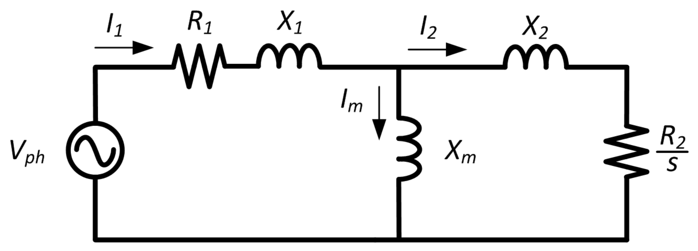
The three main performance indicators of EV motors are efficiency, breakdown torque, and power factor. In EVs, power is supplied from the battery to IM in which the battery capacity determines the driving range. Poor power factor leads to an oversizing of some supply system components which requires more space inside the EVs [40]. The motor’s efficiency needs to increase to reduce the losses through which the driving range can be improved. An adequate breakdown torque is important to have a wider constant power region. A steady-state equivalent circuit model of an induction motor, as shown in Figure 1, is used to derive the performance indicators [41]. In the figure, I 1 , I 2 , and I m represent the stator, rotor, and magnetization currents, respectively, and R 1 and X 1 denote the stator resistance and stator leakage reactance, respectively. R 2 and X 2 indicate the rotor resistance and rotor leakage reactance, respectively, and X m refers to the magnetization reactance.
The efficiency, η of IM is calculated from output power, P o u t and total losses, P l o s s as follows [42]:
η = P o u t P o u t + P l o s s
where P l o s s can be determined as the following [43]:
P l o s s = P s c + P r c + P m v + P i r o n + P s t r a y
The stator and rotor copper losses ( P s c and P r c , respectively) can be calculated as [43]:
P s c = 3 ( I 1 ) 2 R 1
P r c = 3 ( I 2 ) 2 R 2
In this work, 4 poles IM is considered where the mechanical and ventilation losses, P m v are 1.2% from P o u t [39]. The iron losses, P i r o n , can be determined from stator tooth iron losses, P s t , stator yoke iron losses, P s y , and tooth flux pulsation core losses, P t p , using the following expressions [43]:
P i r o n = P s t + P s y + P t p
P s t = K T P B T S b W T f m 50 1.3
P s y = K Y P B C b W Y f m 50 1.3
where P is between 2 and 3 W/kg [39]. B T S is the stator tooth flux density, B C is the stator yoke flux density, W T is the weight of the stator tooth, W Y is the weight of the stator yoke, K T is a coefficient governs core loss augmentation, K Y is a coefficient governs the mechanical machining of stator yoke, f m is a frequency of motor, and b is the Steinmetz coefficient which can be obtained from [39]. P t p can be neglected because it is relatively very small as compared to P s t and P s y . The stray losses, P s t r a y are related to the core losses associated with rotor surface and space harmonic cage losses. In most of the applications, P s t r a y is considered at 1% from P o u t [43]. P s t r a y and P m v in [44] are neglected but they are considered in this work to give more accurate efficiency calculation and consistent with [9].
The breakdown torque, τ b k can be calculated as [45]:
τ b k = 3 p V p h 2 2 ω [ R 1 + R 1 2 + ( X 1 + 1.15 X 2 ) 2 ]
where p represents the number of poles and ω is the angular frequency.
Finally, the power factor of the motor can be computed using the following expression:
cos ϕ = P o u t 3 V p h I 1 η

2.2. Stator Slot Design Parameters

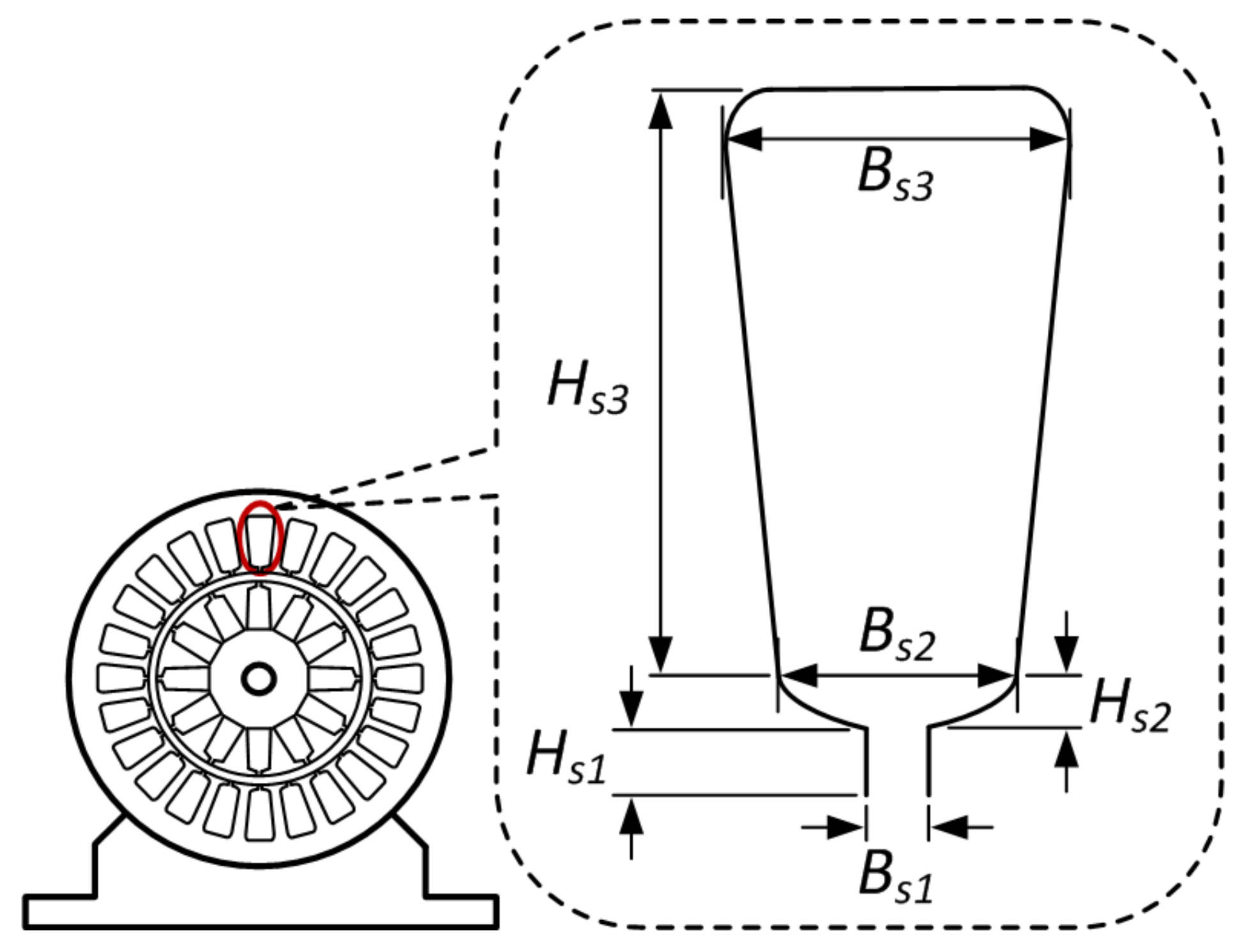
Stator slot geometries become the most relevant part of the IM performance enhancement because of the influence of stator resistance and leakage reactance on the three performance indicators [46]. The stator slot design in this work is based on stator shape, as illustrated in Figure 2. There are six parameters related to the stator slot, namely, stator slot opening width ( B s 1 ), upper width ( B s 2 ), lower width ( B s 3 ), opening height ( H s 1 ), wedge height ( H s 2 ), and height ( H s 3 ), as shown in the figure. Only B s 1 , B s 2 , and H s 3 are selected because they highly impact the magnetization characteristics and affect the stator resistance and reactance. The derivation of stator resistance and leakage reactance from the stator slot parameters is explained in [43]. The parameters are varied within certain limits to avoid the violation of mechanical motor dimensions and ensure the stator tooth flux density is within the allowed range. The parameter settings of stator slots are given in Table 3.
The stator resistance, R 1 , and the stator leakage reactance, X 1 , can be determined using the following expressions [39,43]:
R 1 = L C W ρ c o 80 A c o a 1
X 1 = 4 μ o ω L W 2 λ s p q
λ s 2 H s 3 3 ( B s 2 + B s 3 ) + 2 H s 2 ( B s 1 + B s 2 ) + H s 1 B s 1 1 + 3 K B 4
where L C is the total length of a turn in the stator, W is the number of turns per phase, A c o is the area of the stator conductor, ρ c o 80 is the resistivity of the conductor at 80 °C, a 1 is the number of parallel paths, L refers to the stack length, μ o is the permeability, q represents the number of stator slot per phase, and K B is the chording factor.

2.3. Rotor Slot Design Parameters

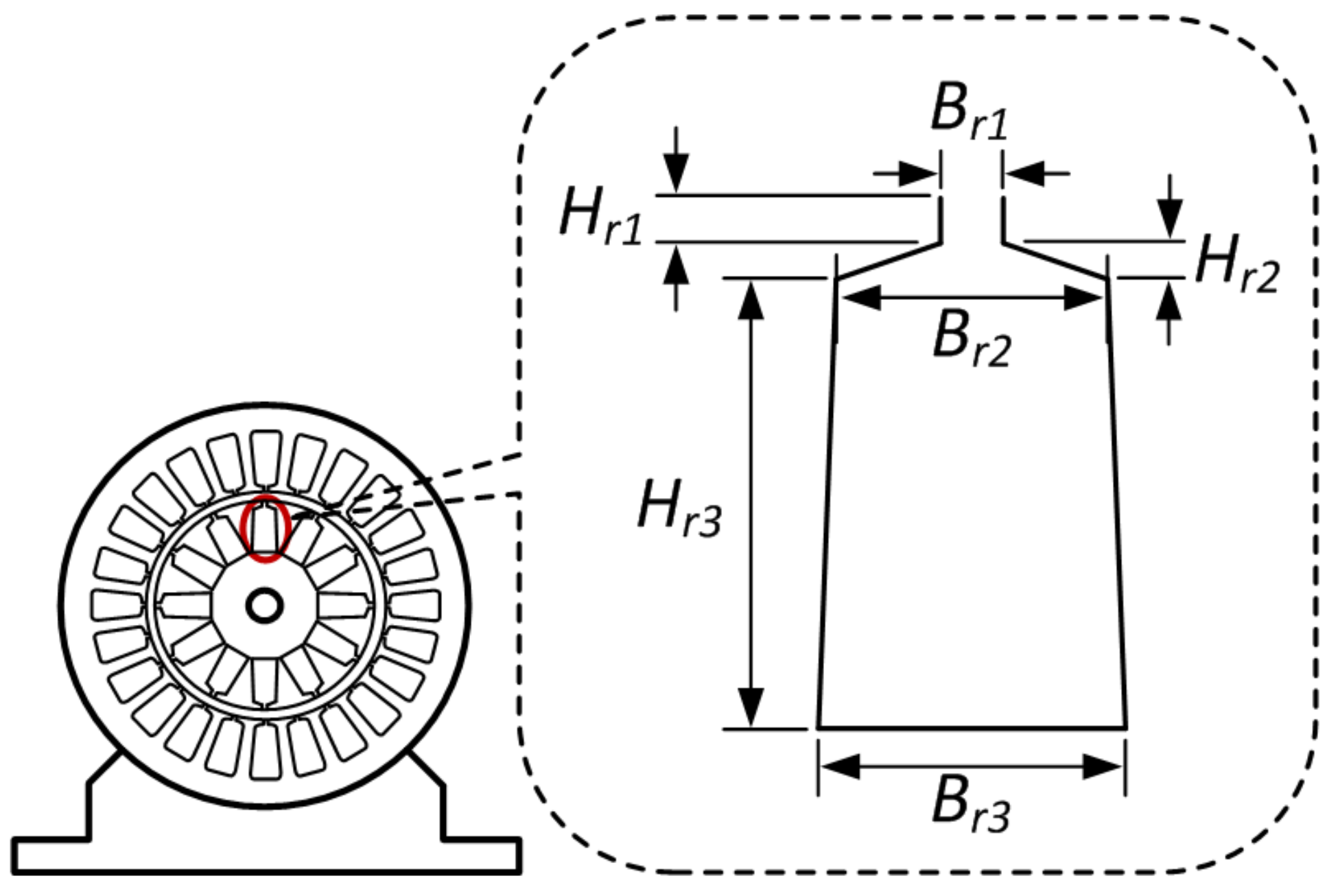
The rotor resistance, R 2 , and rotor reactance, X 2 , are derived from the rotor slot geometries that also influence the three performance indicators. Rotor resistance determines the copper losses related to IM rotor, reducing its efficiency. Furthermore, breakdown torque depends on rotor-leakage reactance, as given in (8). In addition, rotor reactance also has minor impact on reactive power consumption under typical operating conditions which affect the power factor. The rotor slot design parameters are illustrated in Figure 3. The six-rotor slot parametric geometries are rotor slot opening width ( B r 1 ), upper width ( B r 2 ), lower width ( B r 3 ), opening height ( H r 1 ), wedge height ( H r 2 ), and height ( H r 3 ). In this work, only B r 1 , B r 2 , and H r 3 are optimized within the specified limits as in Table 4 to ensure they are not violating the overall design of IM. Similar to the stator slot, the three rotor slot parameters are selected because they highly impact the rotor magnetization characteristics and significantly affect the resistance and reactance of the rotor.
Rotor resistance and reactance can be computed using the following expressions [39,43]:
R 2 = 4 N p h W K W ρ c o 80 L K R N r A b r
X 2 = 4 ( W K W ) 2 ω μ o L K X λ r N r
λ r 2 H r 3 3 ( B r 2 + B r 3 ) H r 1 B r 1 + 3 H r 2 2 B r 1
where N p h is the number of phases, K W is the winding factor, K R is the skin effect coefficient of resistance, N r is the number of rotor slots, A b r is the area of the rotor slot, and K X is the skin effect coefficient of reactance.
This section’s modeling of IM for EV application can be used to obtain an optimal stator and rotor slots design. Therefore, an optimization formulation is required to solve the design problem, which will be discussed in the next section.

3. Optimization Problem Formulation

The IM is modeled by considering the stator and rotor slots design parameters as presented in Section 2. The stator and rotor slots design of IM can be optimized to give the best performance while ensuring IM to operate within the acceptable limits for EVs. As discussed earlier, six parametric geometries of stator and rotor slots ( B s 1 , B s 2 , H s 3 , B r 1 , B r 2 , and H r 3 ) are selected as control variables to give the best performance, which can be performed by maximizing the performance indicators (efficiency, breakdown torque, and power factor) while keeping the control variables (the selected design parameters) within the permissible limits, as given in Table 3 and Table 4. A multi-objective function can be derived from the three performance indicators using the weighted sum method as follows:
f = m a x ( w 1 η + w 2 τ b k , p u + w 3 cos φ )
where τ b k , p u represents the per unit breakdown torque and w 1 , w 2 , and w 3 are weights assigned to each objective function. In this case, an equal weight is used for w 1 , w 2 , and w 3 . In the objective function, a per unit value of the breakdown torque is used, instead of the actual value, to give a balanced treatment between the three performance indicators during the optimization process.
The next following subsections will discuss the proposed OBJSO to solve the optimal stator and rotor slots design problem using the formulated multi-objective function, as expressed in (16). Given that the proposed optimization technique combines JSO and OBL, their original formulations are presented to understand better and highlight the modifications to develop OBJSO.

3.1. Jellyfish Search Optimization

JSO algorithm is a recently introduced swarm intelligent-based meta-heuristic optimization that mimics jellyfish behavior in the ocean [30]. The algorithm works based on the following three main principles:
  • Jellyfishes follow the ocean current;
  • Jellyfishes swim inside the swarm;
  • Time control mechanism.

3.1.1. Jellyfishes Follow the Ocean Current

The jellyfishes follow the ocean current because of a large amount of nutrients [47]. The direction of the ocean current can be determined by calculating the average distance between all jellyfishes and the best jellyfish, as expressed in the following expression [30]:
O c e a n C u r r e n t = i = 1 N p o p ( M * E c M i ) N p o p = M * E c i = 1 N p o p M i N p o p = M * E c μ
where M * is the current best location of jellyfish, E c is a factor that governs the attraction, and μ represents the mean location of all jellyfish. In a normal spatial distribution, jellyfishes are scattered from the mean location given by a distribution coefficient, β . Therefore, E c can be determined by multiplying β and a uniform random variable r 1 in a range between 0 and 1. The direction of the ocean current can be re-written as follows [30]:
O c e a n C u r r e n t = M * β r 1 μ
Then, a new bit k of the i-th jellyfish location can be updated as follows [30]:
M k i ( t + 1 ) = M k i ( t ) + r 2 O c e a n C u r r e n t
where r 2 is another random variable in range [0,1].

3.1.2. Jellyfishes Swim Inside the Swarm

Jellyfishes exhibit two types of motion when they swim inside the swarm: passive motion (type A) and active motion (type B). The jellyfishes in the swarm exhibit type A motion at the beginning of the swarm formation and exhibit type B motion over time. In the type A motion, the new bit k of i-th jellyfish location is now updated using the following expression [30]:
M k i ( t + 1 ) = M k i ( t ) + r γ ( U b , k L b , k )
where r is a random variable in range [0,1] and γ is a motion coefficient. U b , k and L b , k are the k-th bit of upper and lower bounds, respectively.
On the other hand, the new bit k of the i-th jellyfish location in type B motion is updated using the following expression [30]:
M k i ( t + 1 ) = M k i ( t ) + r M o t i o n
where M o t i o n is the direction of motion of jellyfish that exhibits type B motion. In this motion, another j-th jellyfish is required for comparison purposes to evaluate the current i-th jellyfish’s performance. The j-th jellyfish is selected at random. Then, M o t i o n can be determined using the following condition [30]:
M o t i o n = M j ( t ) M i ( t ) , if f ( M i ) f ( M j ) M i ( t ) M j ( t ) , if f ( M i ) < f ( M j )
A time control function is used to control the selection between passive and active motions. It is also used to select between swim inside the swarm and follow the ocean current.

3.1.3. Time Control Mechanism

A time control mechanism is used in JSO to regulate different movements. In the first stage, it is used to decide either the jellyfish will follow the ocean current or swim inside the swarm. The time control function, T c varies randomly in an initial range of [0,1], but it reduces monotonously along the iteration as expressed by the following [30]:
T c ( t ) = ( 1 t T ) × ( 2 r 1 )
where t is the current iteration and T is total number of iterations. The value of T c ( t ) is compared to a constant, T 0 . The jellyfishes are decided to follow the ocean current if T c ( t ) is greater or equal to T 0 or swim inside the swarm otherwise. In the second stage, when jellyfishes are decided to swim inside the swarm, a function is derived from T c as 1 T c ( t ) to select either type A or B motion. The value of 1 T c ( t ) is compared with r (a random variable in range [0,1]). Type A motion is selected if r is higher than 1 T c ( t ) ; or otherwise, type B motion is selected.
After all, the new location of jellyfish needs to be checked for any boundary violations. If the boundary is violated, the jellyfish is brought back into the search space using the following condition [30]:
M i = M k i U b , k + L b , k , if M k i > U b , k M k i L b , k + U b , k , if M k i < L b , k

3.2. Opposition-Based Learning

The OBL technique was introduced by Tizhoosh in 2005 [32]. It is employed in optimizations to allow simultaneous search in the opposite direction along with the current search direction. If the current solutions are far from the globally optimal solution (i.e., on the opposite side), their opposite direction could lead to the solution. Thus, it improves the exploration capability and helps to escape from the local optimum. The application of OBL to generate an opposition location in search space is explained in the next paragraph.
Let M R be a real number within a set interval, where M [ L b , U b ] . The opposite of M ( M ¯ ) can be determined as follows:
M ¯ = L b + U b M
In the same way, the opposition of a high-dimensional variable can be obtained. Let M ( m 1 , m 2 , m 3 , , m d ) be a location in a d dimensional space, where M k [ L b , k , U b , k ] and ( m 1 , m 2 , m 3 , , m p ) R . The opposition of the location in the search space can be obtained as follows [36]:
M k ¯ = L b , k + U b , k M k

3.3. Opposition-Based Jellyfish Search Optimization

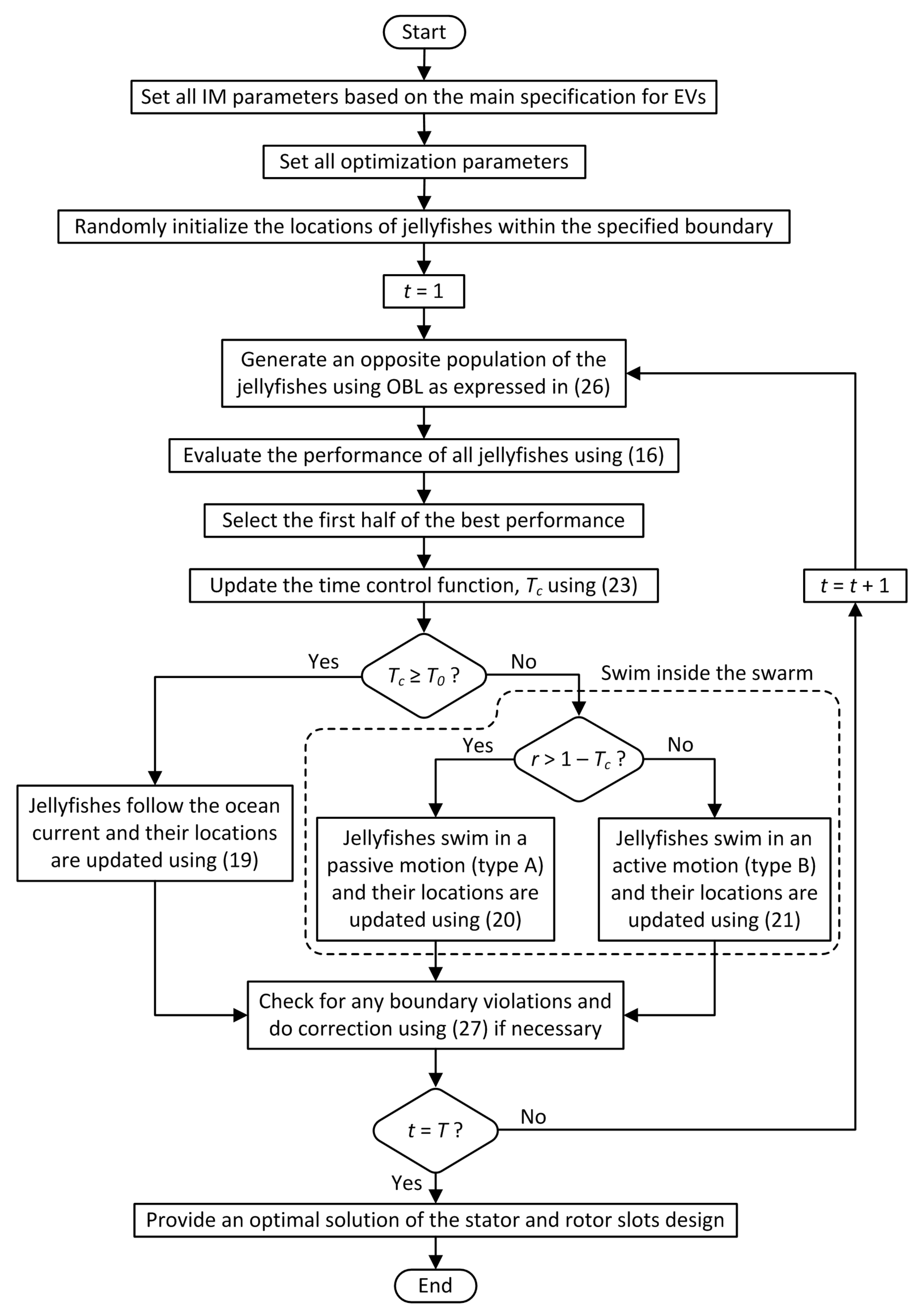
In this study, OBJSO is proposed to enhance the performance of JSO by adopting OBL. An opposition population, M ¯ p o p is generated from the obtained population using JSO, M p o p , by applying (26) after a new location is updated in each iteration or initialization in the first iteration. Then, the performance of M p o p and M ¯ p o p is evaluated, and only the first half of the best performance is selected to maintain the population size, N p o p for the optimization process. In this way, OBL explores any better solutions in opposite locations of the suggested solutions by JSO to improve exploration capability. This process continues until the stopping criteria is met. In this work, the optimization process is stopped when the number of iterations reaches the maximum for overall performance evaluation purposes.
Apart from adopting OBL, the boundary correction mechanism in (24) is modified because of a convergence issue. In the original mechanism, the violated jellyfish position is relocated to the opposite site of search space according to the distance from the violated boundary. This mechanism is almost similar to OBL, but it uses an outside position instead. The mechanism is unsuitable for OBJSO because of the redundancy of the operation, ultimately jeopardizing the decision of JSO. Therefore, the violated jellyfish position in OBJSO is relocated to the nearest boundary as follows:
M i = U b , k , if M k i > U b , k L b , k , if M k i < L b , k
In the suggested boundary correction, the jellyfish position is limited to the search space boundary in the same direction of the position updating procedure by JSO. The same boundary correction is used in other optimization techniques, including JSO, to highlight the effectiveness of the OBL application. In the OBL application, the original population is kept and evaluated together with the opposition population to maintain the advantages of JSO while getting the benefits of OBL. The proposed OBJSO is then applied to solve the optimal design of stator and rotor slots for EV application. Figure 4 shows an overall flowchart of the OBJSO application derived from the formulation discussed earlier. In the next section, the performance of OBJSO is tested and compared with the conventional meta-heuristic optimizations, such as GA, PSO, and JSO, in solving the optimal design of stator and rotor slots problem.
4. Results and Discussion

An analytical model of IM based on the EV requirement is modeled and optimized using OBJSO within a MATLAB software environment using a PC of 2.4 GHz and 8 GB RAM. The performance of OBJSO is compared with other conventional meta-heuristic optimizations, including GA [9], PSO [24], and JSO. The parameter settings for the optimization techniques are tabulated in Table 5. The performance of initial design of the IM, as suggested in [9], is carried out to showcase the improvement that can be achieved using the proposed technique. Table 6 shows the performance of IM based on the initial parameter settings of 1.3 mm, 5.1 mm, 22.9 mm, 0.91 mm, 3.75 mm, and 9.29 mm for B s 1 , B s 2 , H s 3 , B r 1 , B r 2 , and H r 3 , respectively. The performance of developed analytical model is very much similar to the reported performance in [9].

4.1. Optimization Performance Comparison

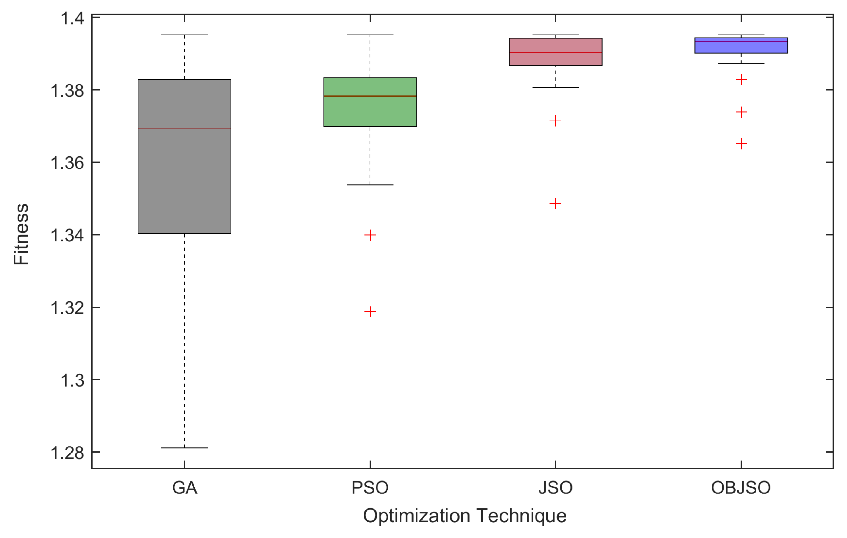
Figure 5 shows a performance comparison of the four optimization techniques in solving the optimal design of stator and rotor slots after 30 runs. The box plot with a narrow band at the higher position indicates more precise and accurate solutions. In this case, OBJSO provides the most precise and accurate solution because its box plot band is narrow and the inter-quartile range, average, median, and worst values are superior to others. The performance of JSO is not far behind OBJSO, which gives accurate solutions but is less precise as its box plot is wider than OBJSO. Significant gaps are found in inter-quartile ranges between JSO and the other two conventional optimization techniques indicating that JSO is more suitable to solve the optimal stator and rotor slots design problem than PSO and GA. Although PSO gives a narrower band than GA, the upper quartile of GA is higher than PSO, which means GA has a better capability to provide more accurate solution than PSO, but it is not consistent. All box plots in the figure show the same best fitness, but their average fitness values are different at 1.3606, 1.3734, 1.3887, and 1.3911 for GA, PSO, JSO, and OBJSO, respectively, which clearly shows that OBJSO outperforms GA, PSO, and JSO in terms of average fitness value by 2.2%, 1.3%, and 0.17%, respectively. Therefore, OBJSO is much better than GA, as suggested in [9], to solve the optimal stator and rotor slots design problem.
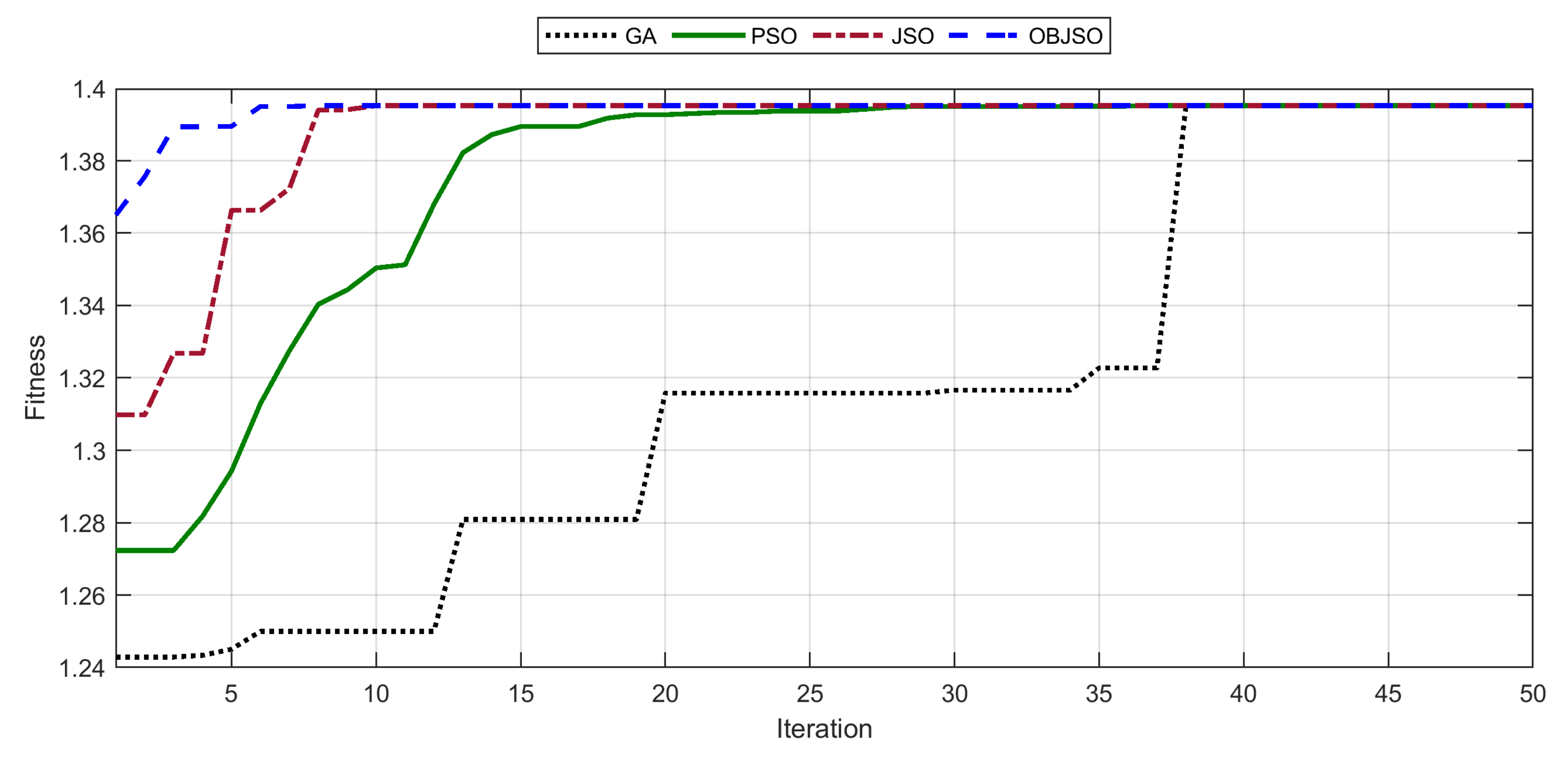
A performance comparison between the optimization techniques in terms of convergence is given in Table 7. According to the results, OBJSO obtains an optimal solution at the fastest convergence rate, where the number of iterations to obtain the optimal solution is the lowest among the optimization techniques in terms of best, average, and worst performance. Furthermore, the good performance of OBJSO is the most consistent as it gives the lowest standard deviation, σ . JSO follows the good convergence performance, and it is the best among the conventional techniques in all aspects. Among the optimization techniques, GA, which is used in [9], is the worst in terms of convergence. Figure 6 illustrates the convergence characteristics of the optimization techniques in obtaining the best fitness solution. It shows that OBL application gives better convergence or improves the exploration of JSO. Overall, the average convergence rate of OBJSO is better than GA, PSO, and JSO by 30.6%, 26%, and 13.6%, respectively. Although OBJSO is the best convergence, it is subjected to a computational burden, as shown by the time taken per iteration, T i t e r , which is mainly due to the adoption of OBL, where additional 1.1 ms per iteration is required after comparing with JSO to compute the OBL. However, the computational time of OBJSO is still better than GA or more specific at 3.67 ms per iteration faster than GA. Ultimately, given the time taken to obtain the best fitness, T b e s t for OBJSO is almost like JSO because it converges faster than JSO. Therefore, OBJSO is a good technique to solve the optimal stator and rotor slots design of IM for EV applications.

4.2. Induction Motor at Optimal Setting

The stator and rotor slots are optimized using OBJSO to maximize the three performance indicators; efficiency, breakdown torque, and power factor, subjected to the parameter settings in Table 3 and Table 4. The obtained optimal design of stator and rotor slots is given in Table 8. All the selected parameters are adjusted to new settings to give better performance. Among the selected parameters, H r 3 or rotor slot height is required the highest adjustment, where 6.29 mm is reduced from the initial setting, and it is followed by H s 3 or stator slot height at 2.9 mm reduction, indicating the initial design is not good when considering other performance indicators, such as breakdown torque and power factor. B r 1 or rotor slot opening width only requires the lowest adjustment for the optimum performance. Overall, the results show that bigger dimensions are required for B s 1 , B s 2 , B r 1 , and B r 2 , and smaller dimensions for H s 3 and H r 3 to give better performance.
Table 9 shows the IM performance based on the optimal stator and rotor slots design parameters. The results are compared with the IM performance at the initial setting to showcase the improvement achieved when the parameters are optimized. The results show that both cases’ efficiency remains the same at 89%. The optimized stator and rotor slots design shows a significant improvement in terms of breakdown torque with an increment of 7.21 Nm or 14.3% improvement. The power factor is slightly increased by 0.005 or 0.6% improvement compared with the initial setting. The optimized motor is further validated by using a finite element method and discussed in the following subsection.

4.3. Model Validation Using Finite Element Method

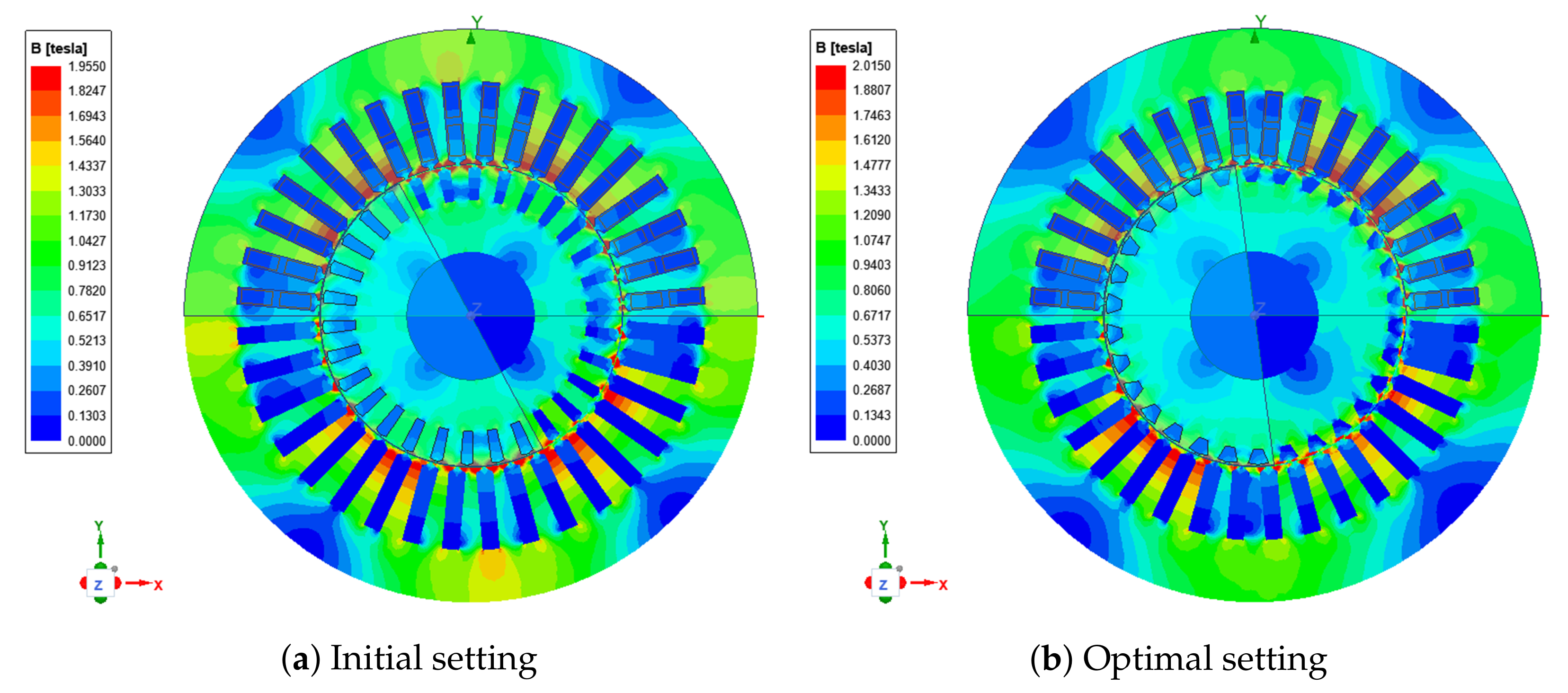
Ansys Maxwell 2D software is used to carry out a finite element analysis for IM model validation in this work. Figure 7 shows the magnetic flux density distribution in IMs from the finite element analysis at initial and optimal settings. The results show that high flux density can be observed near to the stator and rotor slot wedges where the readings are between 1.82 and 1.95 T for initial setting and 1.88 and 2.01 T for optimal setting. The magnetic flux density in the narrowest stator teeth at some places show almost the same readings. However, the high values of flux density only occur at small parts of the IMs and most of the readings are roughly between 1.04 and 1.34 T in both optimal and initial settings. In a comparison between the optimal and initial settings, the optimized motor gives higher flux density than the initial setting especially at narrow places. The higher flux density is mainly due to a significant rotor slot width increment and rotor slot depth reduction from the initial setting. Nevertheless, the magnetic flux density is still below than the design constraints at 2.1 and 2.2 T for stator and rotor teeth, respectively [9]. This clearly indicates that the optimal setting is a feasible IM design solution for EV applications.

5. Conclusions

This work introduces a new optimization technique called OBJSO, which combines JSO and OBL, to solve the optimal stator and rotor slots design of IM for EV applications. Three performance indicators, namely, efficiency, breakdown torque, and power factor, are formulated as a multi-objective function using the weighted sum method. The performance of OBJSO is tested and compared with three existing meta-heuristic optimization techniques, such as GA, PSO, and JSO. The results show that OBJSO outperforms GA, PSO, and JSO in terms of average fitness by 2.2%, 1.3%, and 0.17%, respectively. On the other hand, the convergence rate of OBJSO is improved tremendously, reaching up to a 13.6% reduction on average compared with JSO. The optimized IM provides adequate efficiency in the initial setting and improves the breakdown torque and power factor by 14.3% and 0.6%, respectively. Therefore, the proposed optimal motor design technique can be useful for automotive engineers to design a high performance of IM for EVs at a preliminary stage as an alternative to the used expensive permanent magnet motors. However, the investigated IM based on design parameters in [9] operates at high flux density and it becomes the main limitation of this work. A more suitable IM design that operates at lower flux density or applied field model can be considered in the future to address the limitation. Furthermore, additional parameters and control schemes can be included to evaluate the potential performance improvement for EV applications.

Author Contributions

Conceptualization, A.I.S.J. and A.A.I.; methodology, A.I.S.J. and A.A.I.; software, A.I.S.J. and A.A.I.; validation, A.A.I. and M.A.A.M.Z.; formal analysis, A.I.S.J. and A.A.I.; investigation, A.I.S.J. and A.A.I.; resources, A.I.S.J.; data curation, A.I.S.J. and A.A.I.; writing—original draft preparation, A.I.S.J.; writing—review and editing, A.A.I., M.A.A.M.Z., M.A.Z. and M.A.R.; visualization, A.I.S.J. and A.A.I.; supervision, A.A.I. and M.A.A.M.Z.; project administration, A.A.I. and M.A.A.M.Z.; funding acquisition, A.A.I. All authors have read and agreed to the published version of the manuscript.

Funding

This research was funded by Ministry of Higher Education Malaysia and Universiti Kebangsaan Malaysia under grant FRGS/1/2021/TK0/UKM/02/9 and GGPM-2019-031.

Institutional Review Board Statement

Not applicable.

Informed Consent Statement

Not applicable.

Data Availability Statement

Not applicable.

Conflicts of Interest

The authors declare no conflict of interest.

Nomenclature

β Distribution coefficient
cos ϕ Power factor
η Efficiency
γ Motion coefficient
μ Mean location of jellyfishes
μ o Permeability
ω Angular frequency
ρ c o Resistivity of the conductor
τ b k Breakdown torque
a 1 Number of parallel paths
A b r Area of the rotor slot
A c o Area of the stator conductor
bSteinmetz coefficient
B C Stator yoke flux density
B r 1 Rotor slot opening width
B r 2 Rotor slot upper width
B r 3 Rotor slot lower width
B s 1 Stator slot opening width
B s 2 Stator slot upper width
B s 3 Stator slot lower width
B T S Stator tooth flux density
E c Factor of attraction
f m Motor operating frequency
H r 1 Rotor slot opening height
H r 2 Rotor slot wedge height
H r 3 Rotor slot height
H s 1 Stator slot opening height
H s 2 Stator slot wedge height
H s 3 Stator slot height
I 1 Stator current
I 2 Rotor current
I m Magnetization current
K B Chording factor
K R Skin effect coefficient for resistance
K T Coefficient governs core loss augmentation
K W Winding factor
K X Skin effect coefficient for reactance
K Y Coefficient governs mechanical machining of stator yoke
LStack length
L b Lower boundary
L c Total length of a stator turn
MVector of a jellyfish location
N r Number of rotor slots
N p h Number of phases
N p o p Population size
pNumber of poles
P Specific losses in W/kg
P i r o n Iron losses
P l o s s Power losses
P m v Mechanical and ventilation losses
P o u t Power output
P r c Rotor copper losses
P s c Stator copper losses
P s t r a y Stray losses
P s t Stator tooth iron losses
P s y Stator yoke iron losses
P t p Tooth pulsation core losses
qNumber of stator slot per phase
rRandom variable in range [0,1]
R 1 Stator resistance
R 2 Rotor resistance
sSlip of the motor
TMaximum number of iteration
tIteration
T c Time control function
U b Upper boundary
V p h Input voltage
WNumber of turns per phase
w 1 Weight factor for efficiency
w 2 Weight factor for breakdown torque
w 3 Weight factor for power factor
W Y Weight of stator yoke
W T Stator tooth weight
X 1 Stator reactance
X 2 Rotor reactance
X m Magnetization reactance

References

  1. Chan, C.C.; Bouscayrol, A.; Chen, K. Electric, hybrid, and fuel-cell vehicles: Architectures and modeling. IEEE Trans. Veh. Technol. 2010, 59, 589–598. [Google Scholar] [CrossRef]
  2. Wang, Z.; Ching, T.Z.E.W.; Huang, S.; Wang, H.; Xu, T. Challenges faced by electric vehicle motors and their solutions. IEEE Access. 2021, 9, 5228–5249. [Google Scholar] [CrossRef]
  3. Swaraj, R.J.; Archana, T. Comparison of electric motors for electric vehicle application. Int. J. Res. Eng. Technol. 2017, 6, 12–17. [Google Scholar]
  4. Zeraoulia, M.; Benbouzid, M.E.H.; Diallo, D. Electric motor drive selection issues for hev propulsion systems: A comparative study. IEEE Trans. Veh. Technol. 2006, 55, 1756–1764. [Google Scholar] [CrossRef] [Green Version]
  5. Habib, A.; Zainuri, M.A.A.M.; Che, H.S.; Ibrahim, A.A.; Rahim, N.A.; Alaas, Z.M.; Ahmed, M.M.R. A systematic review on current research and developments on coreless axial-flux permanent-magnet machines. IET. Electr. Power. Appl. 2022, 16, 1095–1116. [Google Scholar] [CrossRef]
  6. Ayob, A.; Halim, S.A.; Yusof, Y. Simulation of energy dump converter topology for switched reluctance motors. Int. J. Eng. Technol. 2018, 7, 99–104. [Google Scholar] [CrossRef] [Green Version]
  7. Othman, M.S.; Nuawi, M.Z.; Mohamed, R. Induction motor bearing fault diagnostics using i-kaz™ and decision tree classification. Int. J. Automot. Mech. Eng. 2016, 13, 3361–13372. [Google Scholar] [CrossRef]
  8. Mehmet, C.; Ramzan, A. Design optimization of induction motor by genetic algorithm and comparison with existing motor. Math. Comput. Appl. 2006, 11, 193–203. [Google Scholar]
  9. Akhtar, M.J.; Behera, R.K. Optimal design of stator and rotor slot of induction motor for electric vehicle applications. IET Electr. Syst. Transp. 2018, 9, 35–43. [Google Scholar] [CrossRef]
  10. Xiaoqing, Z. Simulation and research of automobile induction motor drive control system based on MATLAB/Simulink software. In Proceedings of the 2nd International Conference on Materials Science, Machinery and Energy Engineering, Dalian, China, 13–14 May 2017. [Google Scholar]
  11. Alberti, L.; Bianchi, N.; Boglietti, A.; Cavagnino, A. Core axial lengthening as effective solution to improve the induction motor efficiency classes. IEEE Trans. Ind. Appl. 2014, 50, 218–225. [Google Scholar] [CrossRef]
  12. Lee, G.; Min, S.; Hong, J.P. Optimal shape design of rotor slot in squirrel-cage induction motor considering torque characteristics. IEEE Trans. Magn. 2013, 49, 2197–2200. [Google Scholar] [CrossRef]
  13. Cheng, S.; Li, S.; Chai, F.; Gong, H. Research on induction motor for mini electric vehicles. In Proceedings of the 2012 International Conference on Future Electrical Power and Energy Systems, Sanya, China, 21–22 February 2012. [Google Scholar]
  14. Dianati, B.; Kahourzade, S.; Mahmoudi, A. Axial-Flux Induction Motors for Electric Vehicles. In Proceedings of the 2019 IEEE Vehicle Power and Propulsion Conference, Hanoi, Vietnam, 14–17 October 2019. [Google Scholar]
  15. Dianati, B.; Kahourzade, S.; Mahmoudi, A. Optimization of axial-flux induction motors for the application of electric vehicles considering driving cycles. IEEE Trans. Energy Convers. 2020, 35, 1522–1533. [Google Scholar] [CrossRef]
  16. Khazi, S.; Vadde, A.; Manickavasagam, K.; Kadambi, G.R.; Narayanan, V.; Lokesh, B.M.; Sarkar, S. Analyzation of Temperature Rise in Induction Motor for Electric Vehicles. In Proceedings of the 1st International Conference on Energy, Materials Sciences & Mechanical Engineering 2020, Delhi, India, 31 October–1 November 2020. [Google Scholar]
  17. Priyanka, C.P.; Nithin, S.N.; Jagdanand, G. Thermal Analysis of Multi phase Induction Motor for Electric Vehicle Applications. In Proceedings of the IEEE Transportation Electrification Conference & Expo, Anaheim, CA, USA, 15–17 June 2022. [Google Scholar]
  18. Gundogdu, T.; Zhu, Z.Q.; Mipo, J.C. Analysis of coil pitch in induction machines for electric vehicle applications. IET Electr. Power Appl. 2020, 14, 2525–2536. [Google Scholar] [CrossRef]
  19. Yushaizad, Y.; Kamarulzaman, M. Modeling, simulation and analysis of induction motor for electric vehicle application. Int. J. Eng. Technol. 2018, 7, 145–150. [Google Scholar]
  20. Sinisa, J.; Khwaja, M.R.; John, C.M.; Peter, J.S. Induction machine design and analysis for general motors e-assist electrification technology. IEEE Trans. Ind. Appl. 2014, 51, 631–639. [Google Scholar]
  21. Wang, T.; Zheng, P.; Zhang, Q.; Cheng, S. Design characteristics of the induction motor used for hybrid electric vehicle. IEEE Trans. Magn. 2005, 41, 505–508. [Google Scholar] [CrossRef]
  22. Guan, Y.; Zhu, Z.Q.; Afinowi, I.; Mipo, J.C. Influence of machine design parameters on flux weakening performance of induction machine for electrical vehicle application. IET Electr. Syst. Transp. 2015, 5, 43–52. [Google Scholar] [CrossRef]
  23. Ibrahim, A.A.; Mohamed, A.; Shareef, H.; Ghoshal, S.P. Optimal Power Quality Monitor Placement in Power Systems Based on Particle Swarm Optimization and Artificial Immune System. In Proceedings of the 3rd Conference on Data Mining and Optimization (DMO), Putrajaya, Malaysia, 28–29 June 2011. [Google Scholar]
  24. Duan, Y.; Harley, R.G. A novel method for multiobjective design and optimization of three phase induction machines. IEEE Trans. Ind. Appl. 2011, 47, 1707–1715. [Google Scholar] [CrossRef]
  25. Nell, M.; Kubin, A.; Hameyer, K. Multi-stage optimization of induction machines using methods for model and parameter selection. Energies 2021, 14, 5537. [Google Scholar] [CrossRef]
  26. Gundogdu, T.; Zhu, Z.Q.; Mipo, J.C. Optimization and Improvement of Advanced Non overlapping Induction Machines for EVs/HEVs. IEEE Access. 2022, 10, 13329–13353. [Google Scholar] [CrossRef]
  27. Mallik, S.; Mallik, K.; Barman, A.; Maiti, D.; Biswas, S.K.; Deb, N.K.; Basu, S. Efficiency and cost optimized design of an induction motor using genetic algorithm. IEEE Trans. Ind. Electron. 2017, 64, 9854–9863. [Google Scholar] [CrossRef]
  28. Tutelea, L.; Boldea, I. Induction Motor Electromagnetic Design Optimization: Hooke Jeeves Method Versus Genetic Algorithms. In Proceedings of the 12th International Conference on Optimization of Electrical and Electronic Equipment, Brasov, Romania, 20–22 May 2010. [Google Scholar]
  29. Lee, D.; Jung, H.C. Cost pattern value method for local search algorithms applied to optimal FEA-based design of induction motors. IEEE Trans. Magn. 2017, 54, 1–8. [Google Scholar] [CrossRef]
  30. Chou, J.S.; Truong, D.N. A novel metaheuristic optimizer inspired by behavior of jellyfish in ocean. Appl. Math. Comput. 2020, 389, 1–47. [Google Scholar] [CrossRef]
  31. Abdel-Basset, M.; Reda Mohamed, R.; Chakrabortty, R.K.; Ryan, M.J.; El-Fergany, A. An improved artificial jellyfish search optimizer for parameter identification of photovoltaic models. Energies 2021, 14, 1867. [Google Scholar] [CrossRef]
  32. Tizhoosh, H.R. Opposition-Based Learning: A New Scheme for Machine Intelligence. In Proceedings of the International Conference on Computational Intelligence for Modelling, Control and Automation, and International Conference on Intelligent Agents, Web Technologies and Internet Commerce, Vienna, Austria, 28–30 November 2005. [Google Scholar]
  33. Rahnamayana, S.; Tizhoosh, H.R.; Salama, M.M.A. Opposition-Based Differential Evolution. Adv. Differ. Evol. 2008, 143, 155–171. [Google Scholar]
  34. Malisia, A.R.; Tizhoosh, H.R. Applying Opposition-Based Ideas to the Ant Colony System. In Proceedings of the 2007 IEEE Swarm Intelligence Symposium, Honolulu, HI, USA, 1–5 April 2007. [Google Scholar]
  35. Shaw, B.; Mukherjee, V.; Ghoshal, S.P. A novel opposition-based gravitational search algorithm for combined economic and emission dispatch problems of power systems. Int. J. Electr. Power Energy Syst. 2012, 35, 21–33. [Google Scholar] [CrossRef]
  36. Wong, L.A.; Shareef, H.; Mohamed, A.; Ibrahim, A.A. An enhanced opposition-based firefly algorithm for solving complex optimization problems. J. Kejuruteraan. 2014, 26, 89–96. [Google Scholar]
  37. Zhou, J.; Fang, W.; Wu, X.; Sun, J.; Cheng, S. An Opposition-Based Learning Competitive Particle Swarm Optimizer. In Proceedings of the 2016 IEEE Congress on Evolutionary Computation, Vancouver, BC, Canada, 24–29 July 2016. [Google Scholar]
  38. Rajpurohit, J. A modified jellyfish search optimizer with opposition based learning and biased passive swarm motion. Ingénierie Systèmes d’Information 2021, 26, 577–584. [Google Scholar] [CrossRef]
  39. Boldea, I.; Nasar, S.A. The Induction Machines Design Handbook, 2nd ed.; Taylor & Francis Group: Boca Raton, FL, USA, 2010; pp. 447–473. [Google Scholar]
  40. Elie, L.; Elisa, K.; Arijit, B.; Krein, P.T. Inverter design considerations for variable-pole induction machines in electric vehicles. IEEE Trans. Power Electron. 2022, 37, 13554–13565. [Google Scholar]
  41. Jagdish, S.; Khushdeep, S.; Harleen, K. Designing of three phase squirrel cage induction motor for good efficiency. Int. J. Eng. Innov. Technol. 2016, 5, 40–45. [Google Scholar]
  42. Ramprasath, E.; Manojkumar, P. Modelling and analysis of induction motor using LabVIEW. Int. J. Power Electron. Drive Syst. 2015, 5, 344–354. [Google Scholar] [CrossRef]
  43. Juhaniya, A.I.S.; Ibrahim, A.A.; Zainuri, M.A.A.M.; Zulkifley, M.A. An analytical model of induction motors for rotor slot parametric design performance evaluation. Int. J. Adv. Comput. Sci. Appl. 2022, in press. [Google Scholar]
  44. Dems, M.; Komeza, K.; Lecointe, J.P. Variation of additional losses at no load and full load for a wide range of rated power induction motors. Electr. Power Syst. Res. 2017, 143, 692–702. [Google Scholar] [CrossRef]
  45. Zhao, N.; Schofield, N. An induction machine design with parameter optimization for a 120-kW electric vehicle. IEEE Trans. Transp. Electr. 2020, 6, 592–601. [Google Scholar] [CrossRef]
  46. Yetgin, A.G.; Turan, M.; Cevher, B.; Canakoglu, A.C.; Gun, A. Squirrel cage induction motor design and the effect of specific magnetic and electrical loading coefficient. Int. J. App. Math. Electron. Comput. 2018, 7, 1–8. [Google Scholar] [CrossRef]
  47. Chou, J.S.; Truong, D.N. Multi objective optimization inspired by behavior of jellyfish for solving structural design problems. Chaos Solitons Fractals 2020, 135, 1–26. [Google Scholar] [CrossRef]
Figure 1. IM steady-state equivalent circuit.
Machines 10 01217 g001
Figure 2. Stator slot shape of induction motor and its parameters.
Machines 10 01217 g002
Figure 3. Rotor slot shape of induction motor and its parameters.
Machines 10 01217 g003
Figure 4. Flowchart of OBJSO for optimal stator and rotor slots design.
Machines 10 01217 g004
Figure 5. A performance comparison in terms of fitness.
Machines 10 01217 g005
Figure 6. Convergence curves for best fitness value.
Machines 10 01217 g006
Figure 7. Magnetic flux density distribution in the investigated IMs.
Machines 10 01217 g007
Table 1. Main design specifications of IM [9].
Design SpecificationParameter Settings
Power rating (hp)5
Voltage ( V p h )110
Number of phases3
Number of poles4
Stator winding connectionDelta
Rotor typeSquirrel cage
Base frequency (Hz)80
Rated current (A)15.4
Synchronous speed (rpm)2400
Table 2. Main dimensions of IM [9].
Dimension ParametersSettings
Core length (mm)109
Stator outer diameter (mm)170
Stator inner diameter (mm)90
Airgap length (mm)0.35
Rotor outer diameter (mm)89.3
Rotor inner diameter (mm)38
Number of stator slots36
Number of rotor slots30
Table 3. Parameter settings of stator slot [9].
Stator Slot ParametersSettings (mm)Type
B s 1 0.5–2Variable
B s 2 2–5.2Variable
B s 3 5.1Fixed
H s 1 0.5Fixed
H s 2 1.0Fixed
H s 3 20–30Variable
Table 4. Parameter settings of rotor slot [9].
Rotor Slot ParametersSettings (mm)Type
B r 1 0.2–1Variable
B r 2 3–6Variable
B r 3 2.75Fixed
H r 1 0.5Fixed
H r 2 0.5Fixed
H r 3 3–15Variable
Table 5. Optimization parameter settings.
ParametersGAPSOJSOOBJSO
SelectionRoulatte wheel---
Mutation rate20%---
Crossover rate90%---
Control-Monotonously decreaseMonotonously decrease
mechanism weight factorselection probability
C 1 , C 2 -1.8--
T 0 --0.5
β --3
γ --0.1
Table 6. Performance of IM based on the initial design settings.
Performance IndicatorsValue
Efficiency, η 89%
Breakdown torque, τ b k 43.22 Nm
Power factor, cos ϕ 0.828
Table 7. A performance comparison in terms of convergence.
ParametersGAPSOJSOOBJSO
Best3837108
Average41.4039.973631.70
Worst45423230
σ 8.658.458.318.08
T i t e r * (ms)6.372.401.602.70
T b e s t * (s)0.240.090.020.02
* Time taken based on the best convergence to obtain the best fitness.
Table 8. Optimal setting of stator and rotor slots.
ParametersValue (mm)Adjustment (mm)
B s 1 2+0.7
B s 2 5.2+0.1
H s 3 20−2.9
B r 1 1+0.09
B r 2 6+2.25
H r 3 3−6.29
Table 9. Performance of IM after optimization.
Performance IndicatorsValueIncrement
Efficiency, η 89%-
Breakdown torque, τ b k 50.43 Nm7.21 Nm (14.3%)
Power factor, cos ϕ 0.8330.005 (0.6%)
Publisher’s Note: MDPI stays neutral with regard to jurisdictional claims in published maps and institutional affiliations.