Abstract
To replace the worn-out cutter of tunnel boring machines timely, it is crucial to inspect the cutter’s wear. In this work, a novel detection method based on magnetic force is proposed to overcome the drawback of nonlinearity in current detecting technology. The principle is that the magnetic force between the cutter and the permanent magnet linearly decreases with increasing wear. Firstly, the magnetic force is investigated by the finite element simulation to find the optimal placement of the permanent magnet to realize both high linearity and sensitivity. Secondly, a highly-sensitive force sensor with an S shape is designed to measure the magnetic force. The four strain gauges in the force sensor are combined into a Wheatstone bridge to suppress the common-mode effect, such as temperature. Experimental testing on the magnetic force is performed to verify the feasibility of the detection method. The testing result shows that the magnetic force linearly decreases with the increasing wear loss at a rate of −793 mN/mm. The accuracy of the detecting method approaches 1 mm, which is of the same order of magnitude as those in previous studies.
1. Introduction
Due to the advantages of safety, efficiency, and low interference to the surrounding environment, full-face tunnel boring machines (TBMs) have been applied to various rock tunnel projects, such as water delivery, transportation, and mine tunneling [1,2]. The new cutter must replace the worn-out one to ensure the working efficiency of TBM [3]. Thus, it is crucial to inspect the wear during downtime. In the early days, wear detection was mainly accomplished through manual inspection. In recent years, wear prediction or detection has been developed to improve efficiency and safety.
Alber et al. proposed that the rock abrasive index can be used to estimate the cutter wear and investigated the stress dependency of the rock abrasive index [4]. Ren et al. proposed a wear prediction model based on stress analysis and friction energy for TBM in the heterogeneous ground [5]. Wang et al. investigated the cutter wear prediction for a hard rock TBM based on energy analysis [6]. Yang et al. established a wear prediction model involving geological parameters, tunneling data, and other related factors based on the wear mechanism [7]. Sahinoglu et al. proposed the prediction of cutter wear from temperature measurements on TBM discs and cutting face [8]. Su et al. established a prediction model based on the cutter rings’ plastic removal abrasiveness and motion analysis [9]. Based on the contact mechanics, Wang et al. investigated the wear mechanism of the cutter to propose a new theoretical model for cutter wear evolution [10]. Pu et al. predicted the wear state of the cutter by using brain-like artificial intelligence to process and analyze the vibration signal in the dynamic contact between the disc cutter and the rock [11].
The cutter’s wear is related not only to the rock-breaking mechanism, but also to the geometric dimensioning of the disc cutter, rock body-breaking process characteristics, and rock properties mechanism [12]. Thus, it is very difficult to ensure the precision of the prediction model. On the contrary, direct wear detection using sensors or other technology is more reliable and has higher precision.
Wirth added a MOLYUAN additive with a special odor to the disc cutter-bearing lubricants [13]. Oil leakage occurs when the disc cutter is worn to a certain extent. Wang et al. proposed a detection method based on Chirped Fiber Bragg Gratings (GFBG) [14]. The wear shortens the grating area and then narrows the reflection spectrum bandwidth. Ji et al. utilized the series resistance attached to the cutter to detect the wear, wherein the resistance decreases with increasing wear [15].
The aforementioned methods using additive, GFBG, and series resistance increase the manufacturing difficulty of the cutter and cannot be reused. To overcome the above drawback, many researchers proposed non-contact detecting methods. Zhang et al. designed a device for TBM cutter wear based on the principle that the number of laser lines changes with the cutter wear [16]. Bing et al. also utilized the parallel laser light path to realize the detection of cutter wear [17]. Zhang et al. [18] and Guo et al. [19] proposed a technique based on an ultrasonic wave to detect cutter wear. However, the laser and ultrasonic wave both have a significant drawback of inaccurate measurement after rocks cover the disc cutter.
Because the magnetic field has the advantage of being immune to rocks, detections based on magnetic effects, such as eddy current sensors and magnetoresistances sensors, were proposed. Lan et al. designed an online system based on an eddy current sensor to monitor disc cutter wear, and the effects of three types of rock and muddy water mixture on the measurement data were compared [13,20]. Zhang et al. designed a cutter wear monitoring system based on eddy-current sensor technology with a maximum measurement range of 40 mm [21]. Zheng et al. designed a wire-less detecting system for cutter wear using an eddy-current sensor, and the error of cutter wear was less than 0.5 mm in the laboratory [22]. Ren et al. [23] and Sun et al. [24] also developed wireless cutter wear-detecting systems for cutter wear based on eddy-current sensors. Li et al. carried out the temperature compensation for the eddy-current sensor to improve the wear-detecting accuracy [25]. Zhang et al. designed a 3D visual detecting system for disc cutter wear [26]. The eddy current sensor was installed on the linear actuator to obtain the wear on each axial section of the disc cutter. Wang et al. used Ansoft Maxwell simulation to optimize the coil geometry parameters and circuit structure of the eddy current sensor to meet the requirement of TBM disc cutter wear detection [27]. Besides the eddy current sensor, Bai used the inductive proximity sensor to detect the cutter wear [28]; however, a displacement platform is needed to move the sensor, so the volume and cost are both high. Gong et al. designed a magnetoresistive sensor with a Wheatstone bridge structure to detect cutter wear [29]. The magnetic field around the magnetoresistive sensor changes with increasing wear, so the sensor’s resistances change.
However, the above methods based on magnetic effect have the disadvantage of a nonlinear relationship between the output and wear [26,28]. The nonlinearity makes the sensitivity low when the wear is large and increases the calibration workload. In this work, a novel detection method based on magnetic force is proposed to overcome the drawback of nonlinearity. The technique has the advantages of high linearity, high precision, and low cost.
In this paper, the work is arranged as follows. Firstly, the principle and architecture of the detecting system are described in Section 2. Then, the best placement of the permanent magnet is found by finite element simulation in Section 3 to ensure the linear relationship between the magnetic force and wear. In Section 4, a high-precision force sensor is designed to detect the magnetic force. Finally, experimental testing is performed in Section 5 to verify the feasibility and discuss the precision of the detecting method.
2. Principle and Architecture of the Detecting System
The working principle of the detection system for cutter wear using magnetic force is explained by a step-by-step block diagram, as shown in Figure 1. Firstly, the wear makes the diameter of the steel cutter ring decrease. As a result, the volume of steel in front of the permanent magnet is reduced, which makes the magnetic force between the permanent magnet and steel cutter ring decrease. Then, a high-precision force sensor is employed to detect the decreased magnetic force. The output voltage of the force sensor is transformed into the signal processor board to complete the amplification, noise filtering, and analog-digital conversion. Finally, the digital output signal is transformed into a computer for recording.
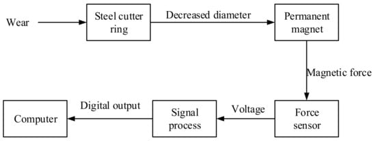
Figure 1.
A step-by-step block diagram describing the working principle of the detection system for cutter wear.
The architecture of the detecting system adopted in this work is shown in Figure 2a. There exist a permanent magnet, a force sensor, and a framework in the detecting system. The permanent magnet and force sensor are fixed together by adhesives to ensure the force sensor can respond to the magnetic force quickly. In current research [20,21,22,23,24,25,26,27], the sensor for cutter wear is commonly located in front of the cutter ring to detect the distance variation induced by the wear, as shown in Figure 2b. However, this commonly used scheme is given up in this work because the relationship between the magnetic force and distance from the steel to a magnet is highly nonlinear [30]. This nonlinearity makes the sensitivity of the magnetic force to the wear become very low when the wear is considerable.
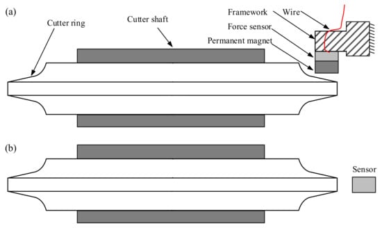
Figure 2.
The architecture of the detecting system, (a) Architecture adopted in this work; (b) Architecture commonly adopted in current research.
On the contrary, the force sensor and permanent magnet are located on the sidewall of the cutter ring in this work. The finite element simulation in Section 3 will show that the magnetic force linearly decreases with the increase in wear. Thus, the sensitivity does not decrease with increasing wear, so the detecting precision can be ensured to be high even though the cutter wear is large. As a result, the robustness of the detecting method is not influenced by the increased wear. Because the detecting method is based on the magnetic effect, the rock or dirt covered on the cutter does not impede the detection. This robustness to rock or dirt is similar to the methods based on eddy current sensors or magnetoresistive sensors [26,28]. Furthermore, the impact resulting from rocks is a major threat to the safety of the wear-detecting system. However, the proposed method has fewer restrictions on the sensors’ protective materials because the magnetostatic field can penetrate a variety of metals or alloys. As a result, the safety of the detecting system can be well guaranteed.
3. Effect of the Placement of the Permanent Magnet on Magnetic Force
The location and orientation of the permanent magnet are crucial for the accuracy of the detection method. This work utilizes finite element simulation to find the optimal placement of the permanent magnet.
3.1. Finite Element Model
The finite element model for the magnetic force is shown in Figure 3a. The cutter shaft is neglected in the model because it is far away from the permanent magnet and has little effect on the magnetic field. A cutter ring made of steel produced by China Railway Construction Heavy Industry Corporation Limited is adopted. For a new cutter, the diameter and width of the cutter ring are 431.6 mm and 76.2 mm, respectively. The blade width is 55 mm, and the acute angle is 40°, as shown in Figure 4. The steel cutter ring and air have a relative permeability of 4000 and 1, respectively. According to the datasheet from the supplier Guangdong Dawa Magnetoelectricity, a remanent magnetization of about 800 [kA/m] is within the permanent magnet, and the length, width, and thickness of the permanent magnet are 50 mm, 30 mm, and 20 mm, respectively, as shown in Figure 4.
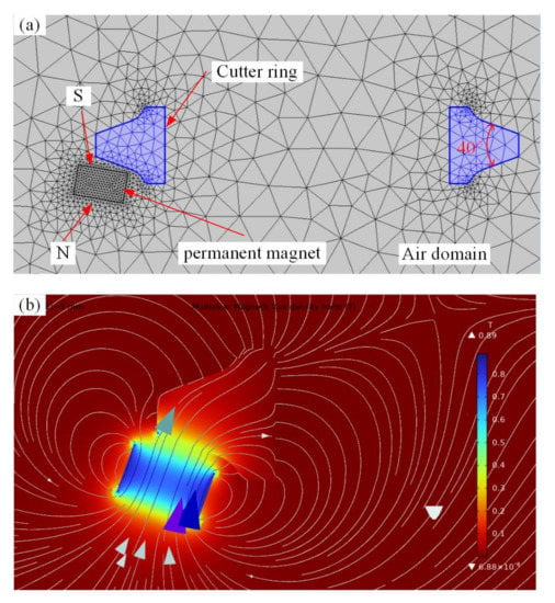
Figure 3.
Finite element simulation of magnetic force: (a) Finite element model; (b) Simulation results of the magnetic field.
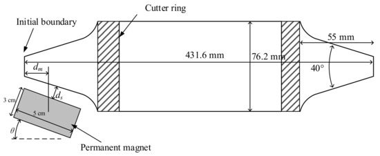
Figure 4.
Schematic diagram of the location and orientation of the permanent magnet.
To describe the wear, an annulus cuts off a portion of the cutter from the outer boundary by Boolean operation. In this work, the location of the permanent magnet is represented by the lateral distance from the permanent magnet’s center to the initial boundary of the cutter ring (dm), and the normal distance from the permanent magnet’s surface to the cutter ring’ surface (ds). The inclination of the permanent magnet represents the orientation (θ), as shown in Figure 4.
The magnetic field between the cutter ring and the permanent magnet is simulated by the Magnetostatics module in the commercial finite element software of COMSOL Multiphysics 6.0 [31]. The simulation result of the magnetic field is shown in Figure 3b. The color in Figure 3b represents magnetic flux density, and the darker the color, the higher the magnetic flux density. The magnetic force between the permanent magnet and cutter ring is calculated through the built-in Force Calculation function of the Magnetostatics module in COMSOL Multiphysics 6.0.
3.2. Simulating Results
The relationships between the magnetic forces and wear losses obtained from the finite element simulation are shown in Figure 5. To investigate the effect of the permanent magnet’s placement on magnetic forces, the lateral distance (dm) varies from 0 mm to 15 mm, the normal distance (ds) varies from 10 mm to 15 mm, and the orientation (θ) varies from 5° to 20°. According to practical engineering experience, the limit of wear is commonly 25~30 mm, so the wear loss increases from 5 mm to 30 mm with a step of 5 mm.
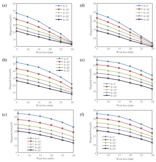
Figure 5.
Effect of the location and orientation of the permanent magnet on the magnetic force: (a) dm = 0 mm, ds = 10 mm; (b) dm = 7.5 mm, ds = 10 mm; (c) dm = 15 mm, ds = 10 mm; (d) dm = 0 mm, ds = 15 mm; (e) dm = 7.5 mm, ds = 15 mm; (f) dm = 15 mm, ds = 15 mm.
It can be seen from Figure 5 that the magnetic force dramatically decreases with increasing wear. It is because the volume of the steel in front of the permanent magnet decreases with increasing wear. It can also be seen that the linearity of the relationship between the magnetic force and wear loss is mainly affected by the inclination of the permanent magnet. The linearity increases with the increasing inclination of the permanent magnet (θ). The reason may be that the volume of the steel in front of the permanent magnet inhomogeneously decreases with increasing wear loss when the inclination (θ) is low.
It can be seen from Figure 5 that the normal distance (ds) has little effect on the linearity of the relationship. However, the magnetic force’s amplitude dramatically decreases when the normal distance (ds) increases from 25 mm to 30 mm, a reduction of about 50%, as shown in Figure 5a,d. The reason is that the magnetic force is inversely proportional to the square of the normal distance [30]. A higher magnetic force leads to a stronger output of the force sensor, so it is supposed to make the permanent magnet close to the cutter surface.
Additionally, it can be seen from Figure 5a–c that the magnetic force increases slightly when the lateral distance (dm) increases. However, the sensitivity of the magnetic force to the wear loss decreases obviously. As a result, it is supposed to adopt a short lateral distance.
As a whole, the lateral distance (dm), normal distance (ds), and orientation (θ) are chosen to be 0 mm, 10 mm, and 20° to realize both high linearity and sensitivity in this work.
4. Force Sensor
This work designs a force sensor to detect the magnetic force. The force sensor is based on the principle that the resistance of strain gauges is sensitive to the strain induced by the force [32]. As shown in Figure 6a, the force sensor contains two flexible parallel beams, and four identical strain gauges are attached to the ends of the two beams. Then, a frame with an S shape fixes the beams’ ends. The frame can be assumed to be rigid because it is much thicker than the flexible beams. When a tensile force applies, the flexible beams bend, and high strains concentrate on the areas attaching the strain gauges. Thus, the bending gives the sensor the advantage of high sensitivity compared to uniaxial tension. Simultaneously, the force sensor has the advantage of low cost because of its simple structure and low-cost strain gauges and material.
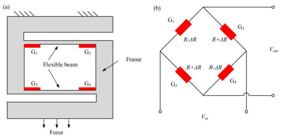
Figure 6.
Principle of the force sensor: (a) schematic diagram of the structure; (b) Wheatstone bridge.
To explain how the force applied on the sensor is converted into the strains, coordinate systems for the two beams are established, wherein the x-axis is along the mid-plane of the beams, as shown in Figure 7a. According to the Euler–Bernoulli beam theory [33], the governing equation and boundary conditions of beams are expressed as
where w denotes the transverse displacement, E denotes Young’s modulus, I the cross-sectional moment of inertia, Q denotes the shear force, l denotes the length of the beam, and F denotes the load applied on the force sensor.
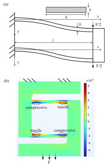
Figure 7.
Bending and strain computation for the flexible beams of the force sensor: (a) schematic diagram of the bending beams; (b) Strain distribution obtained from the finite element simulation.
Integrating Equation (1) with the boundary conditions leading to
According to Equation (2), the strain in the beams is expressed as
In the established systems, the coordinates of G1, G2, G3, and G4 are (0, b/2), (l, b/2), (0, −b/2), and (l, −b/2), respectively. Using these coordinates in Equation (3), the strains of four strain gauges are expressed as
where b denotes the thickness of the beams, as shown in Figure 7a.
It can be seen from Equation (4) that G1 and G4 compress, and G2 and G3 stretch. The strain distribution given in (4) is verified by the finite element simulation, as shown in Figure 7b. Under the applied load, the resistances of the four strain gauges become into
where R denotes the fundamental resistance of the strain gauges, and SS means the sensitivity of resistance to the strain. The four strain gauges are identical, so they must have equal fundamental resistances and sensitivity.
Another advantage of the force sensor is that the four strain gauges can be composed into a Wheatstone bridge to suppress the common-mode effect, such as temperature, as shown in Figure 6b. According to Kirchhoff’s law, the output voltage can be expressed as
where Vout and Vin denote the output and input voltages, respectively. Substituting Equation (5) into (6) leads to the relationship between the output voltage and the input force
The manufactured force sensor is shown in Figure 8a. The width and height are 25 mm and 30 mm, respectively. The flexible beams and frame are both made of steel, and the strain gauges are attached by a white adhesive. The output voltage generated from the force sensor is then input into the differential amplifier and low pass filter to amplify the signal and filter out the high-frequency noise, as shown in Figure 8b. Additionally, an A/D converter is employed to convert the analog signal into a digital signal. Finally, a Bluetooth module transforms the signal into the computer wirelessly. After the calibration, the measuring range of the force sensor is about ±50 N, and the resolution reaches 25 mN.
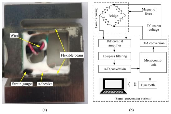
Figure 8.
The manufactured force sensor and its signal processing scheme: (a) sensor; (b) signal processing.
5. Experimental Testing
5.1. Experimental Method
The cutter wear testing is shown in Figure 9. Its main components include a permanent magnet, force sensor, turntable, printed circuit board for signal processing, computer, etc. The permanent magnet is connected with the front end of the force sensor through the adhesive. The magnetic force between the cutter and permanent magnet is tensile for the force sensor. The cutter is mounted on a rotary table to control the direction so that the wear loss in multiple directions can be measured. The adjustable frame for the force sensor adjusts the location and orientation of the permanent magnet to obtain the best performance. The differential amplifier, low pass filter, A/D converter, and Bluetooth module are all integrated into a printed circuit board to realize the signal transmission and processing.
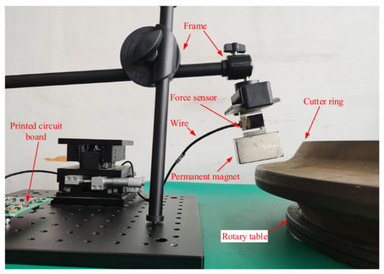
Figure 9.
Experimental testing on the wear detection.
This paper carefully selects six cutters through manual diameter measurement to guarantee their wear loss is about 0 mm, 5 mm, 10 mm, 15 mm, 20 mm, and 25 mm, respectively. The six cutters have identical geometrical dimensions and material properties except for the different wear losses. In actual situations, the wears of the cutter ring along different orientations are inhomogeneous. Meanwhile, the imperfections resulting from the manufacture of the cutter and the installation of the experimental testing system also result in errors, such as the decentration and tilt of the cutter rings. To suppress the effect of these errors, the rotary table rotates with a step of 45° to ensure that every cutter is measured eight times with directions of 0°, 45°, 90°, 135°, 180°, 225°, 270°, and 315°, respectively.
5.2. Experimental Results
The testing relationship between the wear loss and the magnetic force is shown in Figure 10. The inner box is the local zoom of the data points corresponding to the wear loss of 0 mm. It can be seen that there are eight data points corresponding to every wear loss because the cutter is measured eight times with directions of 0°, 45°, 90°, 135°, 180°, 225°, 270°, and 315°. The measured force is lower than the simulated one shown in Figure 5a. This is because there exists an attraction between the steel frame of the force sensors and the permanent magnet. This attraction compensates for a portion of the magnetic force between the cutter ring and the permanent magnet.
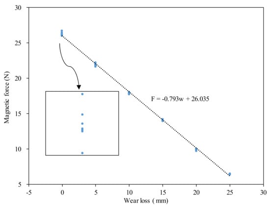
Figure 10.
Experimental test results of cutter wear loss.
It can be seen that when the wear loss increases from 0 mm to 25 mm, the magnetic force almost linearly decreases from 26 N to 6.5 N. Thus, the sensitivity of the proposed method does not decrease with increasing wear loss. On another hand, the methods proposed in [26,28] exhibit obvious nonlinearity, and the sensitivity decreases quickly when the wear loss increases.
To obtain the linear relationship, the least square method is used to fit the data. In other words, the linear relationship must minimize the variance given in Equation (8).
where k0 and k1 are the coefficients to be determined, wi and Fi denote the wear loss and magnetic force of the ith data point, and N denotes the number of data points.
By minimizing the variance, it is found that k0 and k1 are equal to 26.035 N and −0.793 N/mm, respectively. The fitted linear relationship between the wear loss and the magnetic force is also shown in Figure 10. It can be seen that the linear decreasing rate of the magnetic force with the wear loss reaches −793 mN/mm, which is much higher than the resolution of the force sensor at 25 mN. Thus, the detecting method has a high resolution.
To estimate the testing accuracy, the residue errors after the data fitting are calculated by
where Rei denotes the residue error of the ith data point, and ‘k0 + k1wi’ denotes the predicted force using the fitted relationship. In Equation (9), the residue error is divided by k1 to transform the unit of residue error into that of the wear loss. It is convenient in this way to estimate the testing accuracy.
The computed residue errors are shown in Figure 11. There are also eight data points corresponding to every wear loss because the cutter is measured in eight directions. It can be seen that the maximal residue error is lower than 1 mm. In other words, the accuracy of the linear wear-detecting method proposed in this work approaches 1 mm, which is of the same order of magnitude as those obtained in [13,21]. The accuracy of 1 mm is sufficient for decision making regarding changing the disc cutter of TBM because the deviation of 1 mm has little effect on boring efficiency.
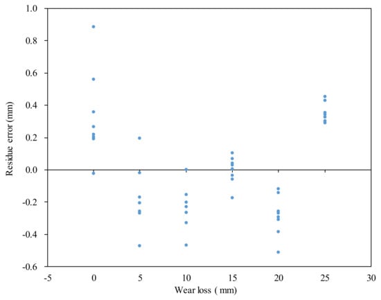
Figure 11.
The residue errors after the linear relationship fitting.
As a whole, the method for detecting the wear of the disc cutter using magnetic force is sufficiently precise and has the advantage of linearity and being low cost.
6. Conclusions
This work proposes a new method using the magnetic force between the cutter and a permanent magnet to detect the cutter’s wear of TBM. Based on the finite element simulation, the lateral distance, normal distance, and orientation of the permanent magnet are chosen to be 0 mm, 10 mm, and 20° to realize both high linearity and sensitivity. A force sensor with two flexible beams is designed to measure the magnetic force. The mechanics’ analysis shows that the force sensor has the advantages of high sensitivity and suppression of the common-mode effect, such as temperature.
The experimental result shows that the magnetic force linearly decreases with increasing wear. The linear change rate of the magnetic force with the wear loss reaches −793 mN/mm. Thus, the sensitivity of the proposed method does not decrease with increasing wear loss. The maximal residue error after linear fitting is lower than 1 mm. In other words, the accuracy of the wear-detecting method proposed in this work approaches 1 mm, which is of the same order of magnitude as those obtained in previous studies. The accuracy of 1 mm is sufficient for decision making regarding changing the disc cutter of TBM because the deviation of 1 mm has little effect on boring efficiency.
One disadvantage of the proposed method is that the force sensor based on the strain gauge is sensitive to temperature. Thus, how to compensate for the temperature effect will be the main focus of future work. Additionally, environmental vibration can also affect the precision by changing the distance from the permanent magnet to the cutter ring. Thus, how to suppress environmental vibration will also be a critical focal point in future work.
Author Contributions
Conceptualization, Investigation, Writing—original draft, J.H. (Jialin Han); Methodology, H.X.; Software, Q.F.; Supervision, Funding acquisition, J.H. (Jiangbo He); Data curation, R.L.; Visualization, W.Z. All authors have read and agreed to the published version of the manuscript.
Funding
This research was funded by the National Natural Science Foundation of China (No. 52205604), the Natural Science Foundation of Sichuan Province of China (No. 2022NSFSC2013), the Chunhui Project Foundation of the Education Department of China (No. 182559).
Data Availability Statement
Data available on request from the authors.
Conflicts of Interest
The authors declare no conflict of interest.
References
- Yang, B.; Chen, S.; Sun, S.; Deng, L.; Li, Z.; Li, W.; Li, H. Vibration suppression of tunnel boring machines using non-resonance approach. Mech. Syst. Signal Process 2020, 145, 106969. [Google Scholar] [CrossRef]
- Chen, G.; Yang, Y.; Huang, T. Vibration analysis of open TBM gripping-thrusting-regripping mechanism. Mech. Mach. Theory 2019, 134, 95–116. [Google Scholar] [CrossRef]
- She, L.; Zhang, S.-r.; Wang, C.; Li, Y.-l.; Du, M. A new method for wear estimation of TBM disc cutter based on energy analysis. Tunn. Undergr. Space Technol. 2023, 131, 104840. [Google Scholar] [CrossRef]
- Alber, M. Stress dependency of the Cerchar abrasivity index (CAI) and its effects on wear of selected rock cutting tools. Tunn. Undergr. Space Technol. 2008, 23, 351–359. [Google Scholar] [CrossRef]
- Ren, D.J.; Shen, S.L.; Arulrajah, A.; Cheng, W.-C. Prediction Model of TBM Disc Cutter Wear During Tunnelling in Heterogeneous Ground. Rock Mech. Rock Eng. 2018, 51, 3599–3611. [Google Scholar] [CrossRef]
- Wang, L.; Kang, Y.; Zhao, X.; Zhang, Q. Disc cutter wear prediction for a hard rock TBM cutterhead based on energy analysis. Tunn. Undergr. Space Technol. 2015, 50, 324–333. [Google Scholar] [CrossRef]
- Yang, J.; Yan, C. Wear Predication of Tunnel Boring Machine Cutters Based on In-situ Measured Data. J. Southwest Jiaotong Univ. 2019, 54, 1283–1292. [Google Scholar]
- Sahinoglu, K.U.; Ozer, U. The prediction of cutter wear from temperature measurements on TBM discs and cutting face. Arab. J. Geosci. 2020, 13, 207. [Google Scholar] [CrossRef]
- Su, W.; Li, X.; Jin, D.; Yang, Y.; Qin, R.; Wang, X. Analysis and prediction of TBM disc cutter wear when tunneling in hard rock strata: A case study of a metro tunnel excavation in Shenzhen, China. Wear 2020, 446–447, 203190. [Google Scholar] [CrossRef]
- Wang, L.; Li, H.; Zhao, X.; Zhang, Q. Development of a prediction model for the wear evolution of disc cutters on rock TBM cutterhead. Tunn. Undergr. Space Technol. 2017, 67, 147–157. [Google Scholar] [CrossRef]
- Pu, X.; Jia, L.; Shang, K.; Chen, L.; Yang, T.; Chen, L.; Gao, L.; Qian, L. A New Strategy for Disc Cutter Wear Status Perception Using Vibration Detection and Machine Learning. Sensors 2022, 22, 6686. [Google Scholar] [CrossRef] [PubMed]
- Burd, H.J.; Houlsby, G.T.; Augarde, C.E.; Liu, G. Modelling tunnelling-induced settlement of masonry buildings. Geotech. Eng. 2000, 143, 17–29. [Google Scholar] [CrossRef]
- Lan, H.; Xia, Y.; Ji, Z.; Fu, J.; Miao, B. Online monitoring device of disc cutter wear—Design and field test. Tunn. Undergr. Space Technol. 2019, 89, 284–294. [Google Scholar] [CrossRef]
- Wang, J.; Zhu, W.; Jiang, L.; Jiang, J.; Liu, T. A multi-channel real-time detection method for tunnel boring machine cutter wear based on Chirped Fiber Bragg Gratings. AIP Adv. 2019, 9, 015312. [Google Scholar] [CrossRef]
- Ji, Z.Y.; Xia, Y.M.; Lan, H.; Yang, M.; Lin, L.K. Cutterhead mud-caking detection method and application based on cutter wear and temperature measurement. J. Adv. Mech. Des. Syst. Manuf. 2019, 13, 13. [Google Scholar] [CrossRef]
- Zhang, B.; Liu, J.Q.; Guo, W. TBM Cutter Wear Detection Device. Patent CN103512527A, 15 January 2014. [Google Scholar]
- Zhang, B.; Liu, J.Q.; Guo, W. Monitoring Device of Disc Cutter Wear on TBM. Patent CN103234903B, 19 August 2015. [Google Scholar]
- Zhang, M.; Yuan, D.; Huang, Q.; Huang, C. Analysis of dynamic abrasion of shield cutters in sandy cobble stratum. Chin. J. Rock Mech. Eng. 2008, 27, 397–402. [Google Scholar]
- Guo, J.B.; Wang, Y.J.; Liu, J.Z.; Niu, J.C. The Research and Design of a New Shield Cutter Wear Detection System. Adv. Mat. Res. 2013, 711, 381–384. [Google Scholar] [CrossRef]
- Lan, H.; Xia, Y.; Zhu, Z.; Ji, Z.; Mao, J. Development of on-line rotational speed monitor system of TBM disc cutter. Tunn. Undergr. Space Technol. 2016, 57, 66–75. [Google Scholar] [CrossRef]
- Zhang, X.B.; Liu, Q.S.; Zhang, J.M. Real-time monitoring technology for wear of cutters and monitoring and analysis of cutterhead vibration of TBM. Tunnel. Constr. 2017, 37, 380–385. [Google Scholar]
- Zheng, W.; Zhao, H.M.; Lan, H.; Tan, Q.; Shu, B.; Xia, Y.M. Design of on-line monitoring system for tunnel boring machine’s disc cutter wear. Instrum. Tech. Sen. 2015, 4, 46–50. [Google Scholar]
- Ren, D.Z.; Sun, X.P. Design on wear detection system for TBM cutter based on CC1101. Min. Process. Equip. 2015, 43, 120–124. [Google Scholar]
- Sun, Z.H.; Zhang, D.L.; Zhang, J.N. Wireless real-time disc cutter wear monitoring system for composite shield machine. Tunnel Constr. 2016, 36, 485–489. [Google Scholar]
- Li, D.; Sun, Z.; Ren, D.; Sun, W. Study of Application of Eddy-current Sensor to Disc-cutter Wear Monitoring System of Shield Machines. Tunnel Constr. 2016, 5, 766–770. [Google Scholar]
- Zhang, M.; Cao, M.; Wei, H. Design of 3D Visual Monitoring System for Shield Disc Cutter Wear. Instr. Tech. Sens. 2021, 9, 58–62. [Google Scholar]
- Wang, F.; Men, C.; Kong, X.; Meng, L. Optimum Design and Application Research of Eddy Current Sensor for Measurement of TBM Disc Cutter Wear. Sensors 2019, 19, 4230. [Google Scholar] [CrossRef]
- Bai, X. TBM cutting tool wear detection system based on displacement sensor. Master’s Thesis, Wuhan University, Wuhan, China, 2018. [Google Scholar]
- Gong, Q.; Wu, F.; Wang, D.; Qiu, H.; Yin, L. Development and Application of Cutterhead Working Status Monitoring System for Shield TBM Tunnelling. Rock. Mech. Rock. Eng. 2021, 54, 1731–1753. [Google Scholar] [CrossRef]
- Schomburg, W.K.; Reinertz, O.; Sackmann, J.; Schmitz, K. Equations for the approximate calculation of forces between cuboid magnets. J. Mag. Mag. Mat. 2020, 506, 166694. [Google Scholar] [CrossRef]
- COMSOL—Software for Multiphysics Simulation. Available online: http://www.comsol.com (accessed on 5 March 2023).
- Liu, M.; Zhang, Q.; Shao, Y.; Liu, C.; Zhao, Y. Research of a Novel 3D Printed Strain Gauge Type Force Sensor. Micromachines 2019, 10, 20. [Google Scholar] [CrossRef]
- Wang, C.; Reddy, J.; Lee, K. Shear Deformable Beams and Plates. Relationships with Classical Solutions; Elsevier: Amsterdam, The Netherlands, 2000. [Google Scholar]
Disclaimer/Publisher’s Note: The statements, opinions and data contained in all publications are solely those of the individual author(s) and contributor(s) and not of MDPI and/or the editor(s). MDPI and/or the editor(s) disclaim responsibility for any injury to people or property resulting from any ideas, methods, instructions or products referred to in the content. |
© 2023 by the authors. Licensee MDPI, Basel, Switzerland. This article is an open access article distributed under the terms and conditions of the Creative Commons Attribution (CC BY) license (https://creativecommons.org/licenses/by/4.0/).