Abstract
To reduce engine vibration, a semi-active controlled magnetorheological suspension is designed. First, the magnetic circuit of the new magnetorheological suspension is simulated. Furthermore, the non-parametric forward and inverse dynamic models of the magnetorheological suspension with the Elman neural network are established, where the modeling results and accuracy are analyzed. Second, according to the characteristics of semi-active vibration control of engine suspension, an improved fruit fly optimized proportional-integral-differential (PID) controller is proposed. Compared with the original fruit fly optimized PID controller and particle swarm optimization PID controller, the control strategies based on the proposed methods are simulated by MATLAB. Then, a vibration control experiment is carried out under different control strategies. The simulation and experiment results show that the PID controller based on the improved fruit fly optimization algorithm has the advantages of short adjustment time and fast dynamic response.
1. Introduction
Magnetorheological fluid (MRF) is a new type of magnetic functional material, which is mainly composed of non-magnetic fluids and small magnetic particles with high permeability and low hysteresis uniformly dispersed in them. In the absence of an applied magnetic field, MRF behaves as a well-flowing Newtonian fluid, whereas, under the action of a magnetic field, it can change from a well-flowing Newtonian fluid to a Bingham semi-solid within an instant (about 10 milliseconds), and this change is reversible [1]. MRF with the characteristics of continuous, reversible, rapid, and easy to control, has a very wide application prospect in aviation, aerospace, automobile industry, hydraulic transmission, biotechnology, and other fields [2,3].
Magnetorheological suspension is an engine suspension device based on MRF. In 2002, Foumani et al. [4] proposed an embedded memory alloy in the rubber main spring of suspension and changed the dynamic characteristics of the suspension through the deformation of the memory alloy. Barber et al. [5] proposed two flow modes of magnetorheological suspension, the dynamic characteristics of which were compared. Khameneifar et al. [6] applied piezoelectric material to the decoupled membrane of active suspension, the decoupled membrane can be controlled according to voltage, so that the dynamic characteristics of suspension can be changed. In 2011, Mansour et al. [7] proposed auxiliary fluid chamber magnetorheological suspension to solve the vibration and noise problems caused by the application of closed-cylinder technology in engines. However, further simplification of magnetorheological suspension structure is an urgent problem to be solved.
Due to the strong nonlinearity of the magnetorheological suspension, it is difficult to establish an effective control method to ensure real-time control. Jones et al. [8] tried to apply fuzzy control to vehicle suspension. Biglarbegian et al. [9] proposed a fuzzy neural network controller for vehicle semi-active suspension. Nguyen et al. [10] designed a magnetorheological support for engines and pump motors, tested with a vibration control scheme based on the skyhook algorithm, which reduced the transfer rate and amplitude of the vibration. Kecikd et al. [11] proposed a closed-loop dynamic control method based on pendulum amplitude and velocity, and a pulse control method based on MR Damper excitation. Braz-Cesar et al. [12] designed a semi-active neural fuzzy controller. Kim [13] proposed a semi-active shared tuned mass damper to adjust the control power on each building in real time, and a multi-input multi-output fuzzy logic controller is developed to control the command voltage. Ata et al. [14] studied the semi-active control method of the suspension system of a tracked vehicle, and three typical control algorithms were simulated. Bathaei [15] studied the seismic performance of a semi-active tuned mass damper and an adaptive magnetorheological damper for an 11-DOF building model by using two fuzzy controllers. In order to evaluate the driving performance of cars, Oh et al. [16] designed a robust sliding mode controller. Mehmet [17] adopted a multi-objective genetic algorithm with six objective functions to optimize the coefficients of the designed PID controller. Aylin et al. [18] proposed a meta-heuristic optimization method for active-tuned mass dampers, where a PID controller was used to control the system. Serdar et al. [19] used a PID controller for an active cable control system of different combinations of multi-layer structures. Serdar et al. [20] proposed an active structural control using a meta-heuristic tuned PID controller to consider time delay and feasible control force. In the meantime, many researchers also studied machine learning for the control of structures [21].
Based on the above studies, this paper proposed a semi-active controlled magnetorheological suspension with improved fruit fly optimization algorithm control strategy. Firstly, a hybrid mode magnetorheological suspension for vehicle engine is designed. Secondly, a non-parametric forward and inverse model of the magnetorheological suspension with Elman neural network is established, where the modeling results and accuracy are analyzed. Thirdly, the improved fruit fly optimization algorithm (IFOA) is applied to the parameter adjustment of the magnetorheological suspension PID controller, so as to improve the vibration isolation performance of the magnetorheological engine and effectively reduce the vibration displacement and vibration acceleration of the body. Finally, the vibration control simulation experiment is established to verify the effectiveness of the proposed control strategy.
2. Structure Design and Magnetic Field Simulation of Magnetorheological Suspension
2.1. Structure Design of Magnetorheological Suspension
The structure and components of the MRF suspension of the engine are shown in Figure 1. Between the upper cover 3 and the lower cover 8 of the engine MRF suspension of the mixed mode, a moving piston 12 and a piston sleeve 6 with a conformal fit and a piston chuck 4 and 7 with an inertial channel are arranged. The liquid chamber is divided into an upper liquid chamber and a lower liquid chamber. An annular decoupling film 11 is arranged outside the piston sleeve in the matching gap of the chuck, and the annular decoupling film is provided with a throttling hole that is misaligned with the inertial channel. The piston is covered with a permanent magnet ring 5 and its outer diameter is machined with thread, which can reduce the settling stability of the MRF. A permanent magnet makes the coil in the absence of current, there will be a certain magnetic field to produce the corresponding damping vibration, which can effectively avoid the occurrence of suspension fault.
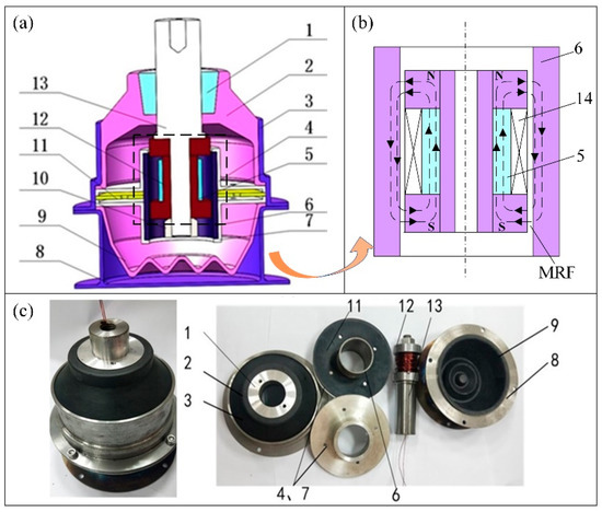
Figure 1.
(a) Schematic diagram of magnetorheological suspension (b) magnetic circuit of magnetorheological suspension (c) physical map. 1 Reinforcing block; 2 rubber main spring; 3 upper cover; 4 upper piston chuck; 5 permanent magnet ring; 6 piston sleeve; 7 lower piston chuck; 8 lower cover; 9 rubber bottom film; 10 nuts; 11 decoupling film; 12 piston; 13 shafts; 14 coil.
2.2. Simulation of Magnetic Field of Magnetorheological Suspension
In order to ensure that the magnetic field required in the damping channel can meet the actual working requirements, magnetic field simulation analysis was carried out using Ansoft Maxwell, and the magnetic field direction and intensity of the working gap were obtained. In this study, KT-450 mineral oil-based magnetorheological fluid developed in the laboratory was used and working temperature of −40 °C~150 °C. B-H curve of MRF KT-450 is shown in Figure 2.

Figure 2.
B-H curve of MRF KT-450.
Using electrical pure iron as the core material, the coil parameters are determined to be 260 turns and 1 mm wire. The magnetic field direction and magnetic field strength of the working gap are shown in Figure 3a,b, respectively, which show the flux path and magnetic induction intensity of the coil cross-section with or without a permanent magnet when the current is 3.0 A. When there is no permanent magnet in the magnetic circuit, the maximum magnetic field strength is 0.79 T, and the magnetic field strength in the damped channel is 0.49 T. In the case of the permanent magnet, the maximum magnetic field intensity is 1.2 T, and the magnetic flux density in the damped channel is about 0.9 T, which can meet the requirements of magnetic saturation of MRF, and the magnetic field intensity is about 320 kA/m, much higher than the case without a permanent magnet.

Figure 3.
(a) The result without permanent magnets (b) the result with permanent magnets.
3. Dynamic Modeling and Control Algorithm of Magnetorheological Suspension
The magnetorheological suspension has strong nonlinear characteristics such as hysteresis, yield, and saturation. A non-parametric model can avoid complex defects of the parametric model, and accurately simulate the dynamic characteristics of the suspension [22,23]. Therefore, the non-parametric model is adopted for the dynamic modeling of the designed magnetorheological suspension. Artificial neural networks can approximate some functions by “learning” from observed data, this is its greatest strength. The positive model obtained by neural networks using experimental data identification can be used to predict the performance of the suspension under other excitation currents. Additionally, the inverse model of the magnetorheological suspension can predict the current to be passed through the excitation coil based on excitation amplitude, frequency, damping force, and other information.
3.1. Elman Neural Network
Elman network is a kind of dynamic feedback network, and travel hysteresis has a short-term memory function. Compared with BP neural network, the Elman network has stronger computing power and a more stable network [24,25]. The structure of the Elman network is shown in Figure 4, which consists of an input unit, implicit unit, output unit, and undertaking unit, and the connection weights among the first three can be constantly changed through learning and correction. The undertaking layer, also known as the context layer or state layer, receives feedback signals from the hidden layer, and the nodes on the hidden layer are connected one-to-one with those on the undertaking layer. The output of the neurons of the accepting layer is delayed and stored so that the input of the hidden layer is the hidden layer state of the previous moment and the network input of the current moment. In this way, the historical state is added, the ability of the network to process dynamic information is also strengthened, and its connection weight is fixed. Generally, the nonlinear function is the transfer function of the hidden layer, and the output layer and the correlation layer are linear functions.
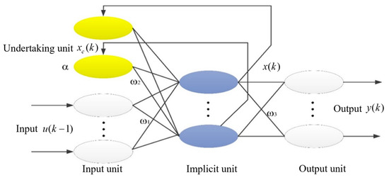
Figure 4.
The structure of Elman network.
The mathematical model of Elman neural network is as follows:
where u is the input of the network, is the output of the hidden layer, is the output of the undertaking layer and is the output of the output unit; is the connection weight of input layer and hidden layer, is the connection weight of undertaking layer and hidden layer, and is the connection weight of hidden layer and output layer; is the self-feedback gain factor of the undertaking layer; f is the transfer function of the neurons in the hidden layer, and is the sigmoid function:
The gradient descent method is used for the training of Elman neural network, aiming to minimize the mean square error of sample output and network identification output, and constantly adjusting the weights of each layer of the network. The specific learning algorithm is as follows:
Define the error function as:
where is the actual output of the network obtained by using the fastest gradient descent method, is the expected output.
3.2. Modeling Results and Analysis of Suspension Positive Model
(1) Processing of original data
Most of the large amount of data obtained by the experiment is used to train the neural network, while the remaining small amount of data are used to verify the accuracy of the network. Due to the different units and ranges of experimental data, some large ranges of data will lead to slow convergence of neural networks and long training time, so the data after normalization processing can be used for neural network train.
(2) Determine the input and output variables of the network
The suspension positive model can predict the suspension damping force. Therefore, take the velocity of the previous time vk−1, displacement xk−1, damping force Fk−1, current Ik−1, and the current excitation frequency fk, velocity vk, displacement xk, current Ik as the input of the neural network, determine the output of the network, that is, the output damping force F at the current moment, D represents the delay unit sampling time, and the identification block diagram is shown in Figure 5.
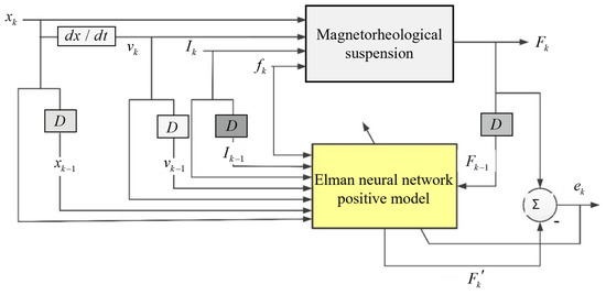
Figure 5.
Identification block diagram of suspension positive model.
(3) Establish an evaluation index of modeling accuracy
Quantitatively evaluate the prediction accuracy of the Elman neural network positive model, and establish the evaluation index:
where is the prediction accuracy of damping force; is the output damping force of suspension measured by experiment; is the positive model identification result of Elman neural network, namely the predicted output damping force of magnetorheological suspension at the current time; is the number of discrete points.
When the excitation frequency is 15 Hz and the amplitude is 5 mm, currents of 0.5 A, 1.5 A, and 3 A are applied, respectively. The relationship between damping force and displacement of the magnetorheological suspension obtained by the test, and the predicted results of the Elman neural network positive model is shown in Figure 6, where the thick solid line represents the experimental results, and the thin dotted line represents the predicted results of the model. As can be seen from the figure, the identification results of the Elman neural network positive model are consistent with the experimental data trend of the dynamic characteristics of the magnetorheological suspension, indicating that the positive model has a high identification accuracy. According to Equation (4), the prediction accuracy of the forward model of the neural network for the suspension damping force can be calculated, as shown in Table 1.
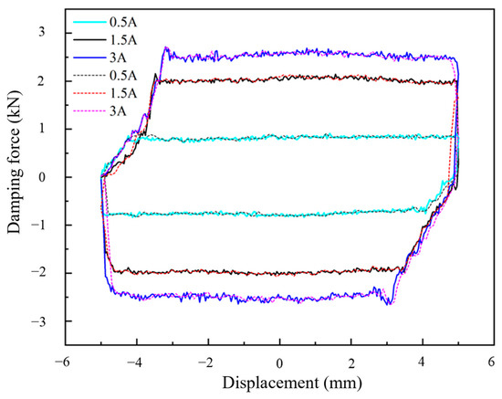
Figure 6.
Curves of experimental and positive model identification results of mounting damping force and displacement under different currents.

Table 1.
Relative approximation accuracy of MR positive model.
3.3. Modeling Results and Analysis of Suspension Inverse Model
(1) Determine the input and output variables of the network
When establishing the non-parametric inverse model of magnetorheological suspension, it is also necessary to normalize the original data of the dynamics experiment first, and then determine the input and output variables of the Elman inverse model [26,27]. The input variable of the inverse model is the displacement x at the previous time k−1, current Ik−1, excitation frequency fk−1, damping force Fk−1, velocity vk−1. Additionally, the current speed vk, displacement xk, excitation frequency fk, damping force Fk, control current Ik required by the current working state of the suspension is the output of the network, D represents the delay unit sampling time, and the identification block diagram is shown in Figure 7.
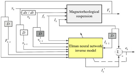
Figure 7.
Identification block diagram of suspension inverse model.
(2) Establish the evaluation index of modeling accuracy
In order to evaluate the accuracy of Elman neural network inverse model, and predict the required excitation current [28], evaluation indexes should also be established:
where is the prediction accuracy of current; is the actual input current in the experiment; is the identification result of Elman neural network inverse model, namely, the required input excitation current at the current moment; is the number of discrete points.
Taking the excitation frequency of 15 Hz and the amplitude of 5 mm as an example, the experimental results of the excitation current required by the magnetorheological suspension and the predicted results of the Elman neural network inverse model are shown in Figure 8. Where the thick solid line represents the experimental results, and the thin dotted line represents the predicted results of the model. It can be seen that the current identified by the Elman neural network inverse model is in good agreement with the current applied in the experiment of the dynamic characteristics of the magnetorheological suspension. This inverse model lays a foundation for the semi-active control of the magnetorheological suspension. Table 2 shows the relative approximation accuracy of the inverse model for magnetorheological suspension. It can be seen that the lowest approximation accuracy of the inverse model of the Elman neural network is 97.18%, indicating that the inverse model of magnetorheological suspension based on the Elman neural network meets the engineering needs.
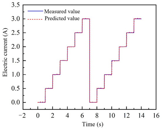
Figure 8.
Curves of identification results of magnetorheological suspension inverse model.

Table 2.
Relative approximation accuracy of magnetorheological suspension inverse mode.
3.4. Neural Network PID Algorithm
PID neuron of neural network is three inputs corresponding to one output [29,30], with three weights of proportional Kp, integral Ki and differential Kd. Among them, the three input neurons, respectively, , and ; The output of the neuron is .
Output of neuron:
Error function:
Neuron weights are adjusted as follows:
where , are the interest rate, and similarly, the adjustment of integral and differential coefficients can be written as:
Thus, the neuron weights (the three parameters of PID) are adjusted as follows:
As the is related to the model of the controlled object, the calculation will be more difficult for the unknown controlled object, so be expressed in the following formula.
In addition, there are many uncertainties in the calculation related to the future output. A controlled system in which the equation () must hold, and which will be introduced into the learning rate:
In order to avoid the oscillation phenomenon caused by too large PID gain coefficient, normalization processing is required, as follows:
Then
3.5. Improved Fruit Fly Optimization Algorithm
The steps of the classical fruit fly optimization algorithm (FOA) can be represented as follows [31]:
(1) The population is initialized to determine the number PA, the maximum number of iterations INmax, the random flight distance FR and the initial position (X-axis, Y-axis) of the Drosophila population.
(2) Each individual fly is given random directions and distances to find food by smell:
Xi = X-axis + 2 × FR × Randi-FR
Yi = Y-axis + 2 × FR × Randi-FR
(3) The between the individual fruit flies and the origin, and the taste concentration determination value Si are calculated, which is the reciprocal of the distance:
(4) By substituting Si into the fitness function, the Smelli value of flavor concentration of Drosophila population is calculated, and the optimal concentration of Drosophila population is found:
(5) The optimal concentration value and its coordinates are retained, and the optimal position is defined as:
(6) When the maximum number of iterations or preset precision value of odor concentration is reached, stop the cycle; otherwise, repeat steps 2 to 4.
In this work, the cloud model algorithm [32,33] is used to adjust the rand function values in the interval [0, 1], shown in Figure 9. Firstly, using known information about the location and concentration of each fly, quantitative data are converted by the reverse cloud generator algorithm into numerical characteristics of qualitative concepts: expected Ex, entropy En, super entropy He. That is, the original fruit fly population is randomly divided to obtain group samples, and each group contains r flies. The in-group sample variance of each group is calculated, and then the forward cloud generator is used to obtain a cloud droplet and its determination, namely the Randk function. In this way, there is a step length in the whole fruit fly population, and each group of fruit fly has the same step length. Sample variance, expected Ex, entropy En, super entropy He, and determinacy can be calculated by the following formula:
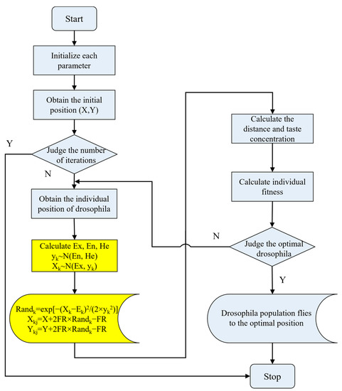
Figure 9.
Improved fruit fly algorithm flowchart.
Among them,
where
There are six steps for the improve fruit fly optimization algorithm (IFOA):
(1) The number of fruit fly population PA, the maximum number of iterations INmax, the number of groups , individual fly distance FR and position X-axis and Y-axis are initialized.
(2) According to the reverse cloud generator algorithm, the expected Ex, entropy En and super entropy He are calculated, respectively, from each group of grouped flies to further determine .
(3) According to the forward cloud generator, the fruit fly and certainty are obtained, and the individual position of the fruit fly is updated.
(4) The distance Disti between each individual fruit fly and the taste concentration decision value Si are calculated.
(5) The flavor concentration of each individual fruit fly is calculated, and the minimum value of flavor concentration and the location information of the corresponding individual fruit fly are saved.
(6) Taking the minimum flavor concentration as the optimal value, the optimal flavor concentration obtained in this optimization is compared with the current preserved optimal flavor concentration. If the optimization result is less than the current value, the optimal flavor concentration value of the fruit fly population is updated, and the corresponding individual position of the fruit fly is saved; otherwise, go to step (2).
4. Simulation Analysis and Experimental Verification
4.1. Establishment of Simulation Module of Magnetorheological Suspension
According to the dynamic equation of the engine mounting system, MATLAB/Simulink module is used to establish the simulation model of a single-degree-of-freedom engine mounting system, as shown in Figure 10 and Figure 11.
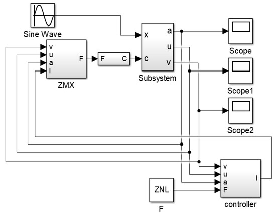
Figure 10.
Simulation model of magnetorheological suspension.
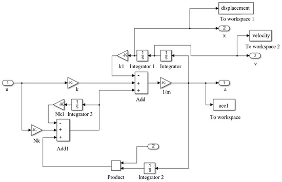
Figure 11.
Subsystem model of magnetorheological suspension.
4.2. Simulation Analysis Based on PID Control
In order to verify the effectiveness of vibration control of IFOA PID controller, vibration control simulation was carried out by using the established single degree of freedom engine mount simulation model. The stiffness of the magnetorheological suspension is set as 165,000 N/m, the variable damping range is 400~2500 Ns/m, the value of N is 3, and the weight of the powertrain is 210 kg. Since the engine adopts three-point suspension, the weight of the powertrain borne by a single suspension is 70 kg. In order to simulate the vibration of the engine, so the input excitation of the simulation model is simple harmonic vibration, the excitation frequency is 29.7 Hz, i.e., idle speed n = 890 r/min, frequency is 99 Hz, i.e., speed n = 2980 r/min of the system were, respectively, carried out PID control simulation. The changes in body acceleration and displacement under PID control based on FOA, PSO-FOA (particle swarm optimization–fruit fly optimization algorithm), and IFOA are compared in Figure 12.
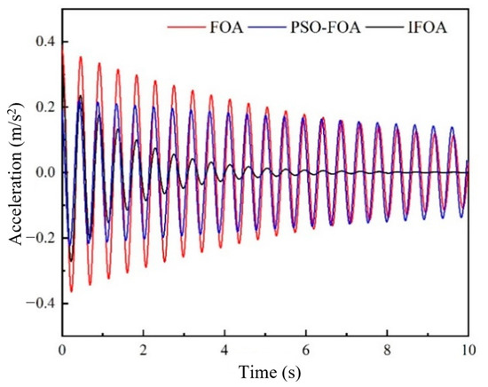
Figure 12.
Vibration acceleration of vehicle body (n = 890 r/min).
Figure 12, Figure 13, Figure 14 and Figure 15 show the acceleration and displacement response of the vehicle body under simple harmonic vibration. Figure 12 and Figure 13 show the acceleration and displacement response of the vehicle body when engine speed n = 890 r/min, respectively. Through comparative analysis of simulation data, it can be found that compared with the other two controllers, the acceleration and displacement peaks obtained by the IFOA method are the smallest. The stability time is the shortest and the vibration acceleration of the body is finally close to zero. Figure 14 shows the acceleration response of the body when the engine speed n = 2980 r/min. It can be seen that, based on FOA, the amplitude-of-PID control of the PSO-FOA algorithm is larger than that of the PID control optimized by the IFOA algorithm, among which FOA has the worst control effect and the peak acceleration is 0.32 m/s2. The acceleration amplitude controlled by the PSO-FOA algorithm is followed by that controlled by the IFOA algorithm, and the acceleration amplitude controlled by the IFOA algorithm is the best, which is 0.16 m/s2. Figure 15 shows the body displacement response when engine speed n = 2980 r/min. The peak-to-peak value of body vibration displacement controlled by the IFOA algorithm decreases by 19.05% and 38.9%, respectively, compared with that of the original FOA and PSO-FOA. Compared with the PID controllers of FOA and PSO-FOA, the PID controller optimized by the IFOA algorithm has better control performance, and the vibration isolation effect of the engine at idle speed and high speed is satisfactory. Due to the limitation of the characteristics of the magnetorheological suspension, it is difficult to achieve the goal of zero vibration displacement of the frame at present.
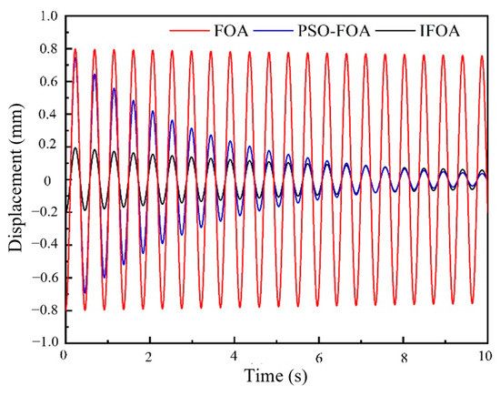
Figure 13.
Vibration displacement of vehicle body (n = 890 r/min).
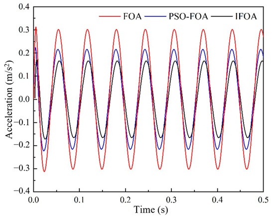
Figure 14.
Vibration acceleration of vehicle body (n = 2980 r/min).
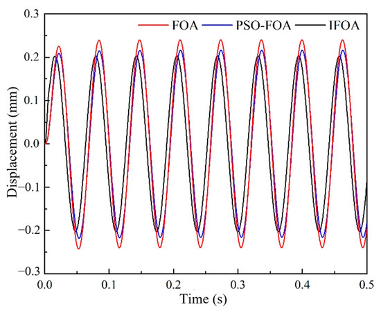
Figure 15.
Vibration displacement of vehicle body (n = 2980 r/min).
4.3. Establishment of the Test Platform for the Magnetorheological Suspension System
Parameters optimization and simulation analysis were carried out on the three PID controllers of FOA, PSO-FOA, and IFOA designed above. In order to verify the controllability of the magnetorheological suspension and the effectiveness of the controller in the practical application process, a simulation test platform for vibration control of magnetorheological engine suspension was built in this chapter. The LabVIEW platform is used for vibration analysis and current control.
In order to test the vibration-damping performance of the magnetorheological suspension system, the schematic diagram of the experimental platform built is shown in Figure 16. The experimental system includes a vibration motor, frequency converter, data acquisition system, and vibration control system. The vibration motor is used to simulate the vibration of the engine itself, and the frequency converter can adjust the speed of the vibration motor to simulate different working states of the engine. The data acquisition system is composed of acceleration, displacement sensor, data acquisition card, etc., which is used to collect, store, and transmit the vibration signal of the test platform. The vibration control system, as the core part of the whole experiment system, is composed of a frequency converter, programmable DC power supply, and host unit. PC LabVIEW platform processes the data collected by the PCI data acquisition card and obtains the control signal of magnetorheological suspension through analysis, namely the excitation current signal required by magnetorheological suspension in the current working state, and sends it to the programmable DC power supply, which then acts on the magnetorheological suspension to realize the control of damping force. Figure 17 shows the experimental platform of the magnetorheological suspension control system.
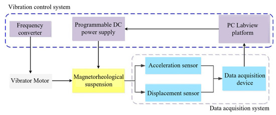
Figure 16.
Schematic diagram of magnetorheological suspension control system.
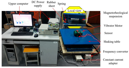
Figure 17.
Test bench of magnetorheological suspension system.
4.4. Experimental Study of Magnetorheological Suspension System
In order to test the actual vibration control effect of the proposed FOA-PID controller, PSO-PID controller, and IFOA-PID controller under various working conditions of the magnetorheological suspension system, a variable speed and frequency modulation system composed of a vibration motor and frequency converter were adopted to simulate different working conditions of the engine under the temperature of 25 °C ± 2 °C. The current control experiment and simple harmonic vibration control experiment were carried out.
(1) DP811A programmable power control experiment
In this paper, the semi-active control of the suspension system is mainly to change the current applied on the suspension according to different vibration states and use the current change to adjust the damping ratio of the MRF to control the actual output damping force of the suspension, so as to achieve the effect of vibration reduction. The current input in the experiment is to transmit the current signal to the DP811A DC power supply through the current control module in the LabVIEW platform. Therefore, the key to the whole vibration reduction experiment is to ensure the accuracy of the output current of the current source. The current control experiment is mainly to check whether the communication between the current source and the LabVIEW current control module in the upper computer is successful and verify whether the output error of the DP811A DC power supply meets the requirements.
The output current commands of 0.5 A and 2 A are applied to the programmable current source through LabVIEW, respectively. The comprehensive results are shown in Figure 18. It can be seen that the DC power supply can complete the required output current command, so it can be seen that the communication between the DC power supply and the LabVIEW current control module is intact, but there is some error in the output current. Through the analysis of the experimental data of 0.5 A current, the average deviation of the output current is 7.543 × 10−0.3, and the relative average deviation is 1.5088%. The peak-to-peak value of the error is 0.0138 A, and the current output is within a reasonable range.
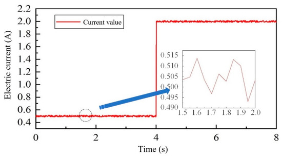
Figure 18.
Control output for programmable current source.
(2) Simple harmonic vibration control experiment
In this experiment, the magnetorheological suspension system is taken as the research object, and the vibration of the vibration motor is used to simulate the simple harmonic motion of the engine itself. The semi-active control experiments are carried out on the magnetorheological suspension system controlled by FOA PID, PSO-FOA PID, and IFOA PID, respectively. During the experiment, the displacement and acceleration signals of the “frame” are collected in real time, and the vibration information is stored for time domain analysis. The experimental results of FOA PID control, PSO-FOA PID control, and IFOA PID control are compared, and the control effect of the designed control algorithm on the mounting system is verified.
Under different control algorithms, the variation curve of the performance index of the engine mounting system is shown in Figure 19, Figure 20, Figure 21 and Figure 22. It can be seen that the peak value of displacement and acceleration of the mounting system controlled by the IFOA PID algorithm is the smallest compared with that controlled by the other two algorithms, indicating that the IFOA PID control algorithm has a better control effect. As shown in Figure 21, the high-frequency acceleration of the suspension system controlled by FOA has a large amplitude oscillation at 1.8 s~2.2 s, and the same oscillation also exists in the suspension system controlled by PSO-FOA within 1.5 s~1 s. The reason is that the vibration motor resonates with other parts in a short time during the vibration process of the suspension system. However, the amplitude controlled by PSO-FOA decreases a lot relatively, while the high-frequency acceleration controlled by FOA does not have instantaneous oscillation of large amplitude, which indicates that the control effect of FOA PID is better.
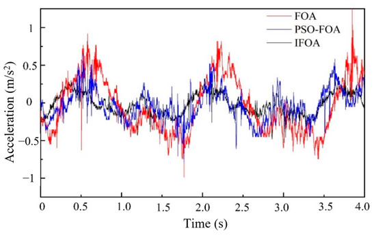
Figure 19.
Acceleration of frame at low-frequency.

Figure 20.
Displacement of frame t at low frequencies.
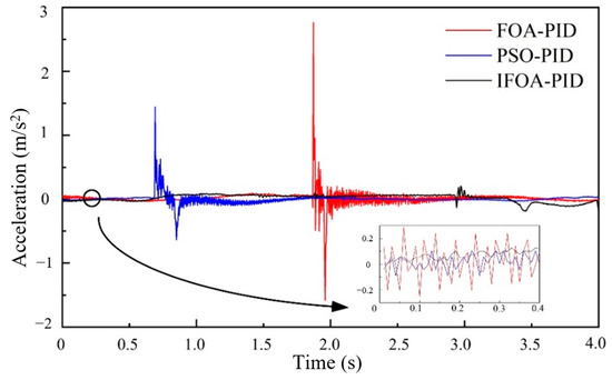
Figure 21.
Acceleration of frame at high-frequency.
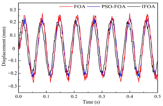
Figure 22.
Displacement of frame t at high frequencies.
In order to analyze the experimental results more accurately, the root mean square value (RMS) of vibration acceleration and displacement of the mounting system controlled by these three algorithms is shown in Table 3. According to the calculation, compared with the FOA PID control algorithm, the low-frequency acceleration and root mean square of displacement of the engine mounting system controlled by the IFOA PID algorithm are improved by 59.80% and 80.03%, respectively, while the high-frequency acceleration and root mean square of displacement are improved by 52.80% and 14.82%, respectively. Compared with the PSO-FOA PID control algorithm, the root mean square values of low-frequency acceleration and displacement of the suspension system controlled by the IFOA PID algorithm are reduced by 30.88% and 67.58%, respectively, and the root mean square values of high-frequency acceleration and displacement are reduced by 21.63% and 5.01%, respectively. It can be proved that the PID control optimized by the IFOA algorithm makes the magnetorheological engine mounting system have better working performance, and further reflects the optimal control effect of the algorithm.

Table 3.
RMS of different frequencies.
5. Conclusions and Future Works
In this work, a hybrid mode semi-active control of magnetorheological suspension is designed, and a non-parametric forward and inverse model of magnetorheological suspension is established. Furthermore, a PID control strategy with an improved fruit fly optimization algorithm is proposed, and the semi-active control of the suspension vibration isolation system is studied experimentally, and the following conclusions are drawn:
(1) Based on the working principle of MRF, a new high-efficiency magnetorheological suspension is designed, and its magnetic field is simulated and analyzed. The results show that: when no permanent magnet, the maximum magnetic induction intensity is 0.79 T, and the magnetic induction intensity in the damping channel is 0.49 T, which is not enough to make MRF reach magnetic saturation. When a permanent magnet is added, the maximum magnetic induction intensity is 1.2 T, the magnetic induction intensity in the damping channel is about 0.9 T, and the magnetic field intensity is about 320 kA/m, which can meet the requirements of the magnetorheological suspension, proving that the suspension structure design is reasonable.
(2) The non-parametric forward and inverse model of magnetorheological suspension based on the Elman neural network and the evaluation index of model prediction accuracy are established. When the applied current of suspension is 0.5 A, 1.5 A, and 3 A, the prediction accuracy of the forward model is 94.98%, 98.26%, and 99.93%, respectively. When the excitation frequency is 15 Hz, the prediction accuracy of the forward model is 94.98%, 98.26%, and 99.93%. When the amplitude is 5 mm, the current value is predicted by the inverse suspension model, and the lowest prediction accuracy is 97.18%, which proves that the established forward and inverse model of magnetorheological suspension can truly predict the output of suspension. The fruit fly optimization algorithm was improved based on the cloud model theory. The results show that when the engine speed n = 890 r/min, the peak value of acceleration and displacement of the vehicle body obtained by the IFOA method is the minimum, and the stability time is the shortest. When the engine speed n = 2980 r/min, the acceleration amplitudes of PID control based on FOA, PSO-FOA, and IFOA are 0.32 m/s, 0.23 m/s2, and 0.16 m/s2, respectively. The peak-to-peak value of body vibration displacement controlled by the IFOA algorithm is reduced by 19.05% and 38.9% compared with the original FOA and PSO-FOA. It can be seen that the PID controller based on IFOA has better control performance and can effectively attenuate vibration.
(3) The control experiment platform of the magnetorheological suspension system is built, and the control experiments were carried out, including the programmable power control experiment and the simple harmonic vibration control experiment. The results show that the DP811A DC power supply achieves effective communication with LabVIEW’s current control module. Compared with FOA PID and PSO-FOA PID control algorithms, the root means square values of the low-frequency acceleration and displacement of the engine mounting system controlled by the IFOA PID algorithm are improved by 59.80%, 80.03%, 30.88%, and 67.58%, respectively. The root mean square values of high-frequency acceleration and displacement are improved by 52.80%, 14.82%, 21.63%, and 5.01%, respectively, which proves that the IFOA PID controller proposed in this paper has a better vibration reduction effect.
However, the IFOA PID semi-active control strategy designed in this paper can effectively control the vibration of the engine mounting system, it is still necessary to further improve the stability and response speed of the control system so that the whole mounting system can obtain a better vibration reduction effect. At the same time, this paper uses a vibration motor to carry out a simulation experiment. Vehicles will be used in the future, which has a positive role in promoting the application of magnetorheological suspension.
Author Contributions
Methodology, L.D.; software, C.F. and D.H.; formal analysis, H.L. and Y.Y.; data curation, X.L. All authors have read and agreed to the published version of the manuscript.
Funding
This research was funded by National Natural Science Foundation of China under Grant 51975568, the Independent Innovation Project of “Double-First Class” Construction of China University of Mining and Technology under Grant 2022ZZCX06, the Natural Science Foundation of Jiangsu Province under Grant BK20191341, the Jiangsu Funding Program for Excellent Postdoctoral Talent under Grant 2022ZB519, the China Postdoctoral Science Foundation under Grant 2022M723387 and Priority Academic Program Development of Jiangsu Higher Education Institutions (PAPD).
Data Availability Statement
Not applicable.
Conflicts of Interest
The authors declare that there are no conflict of interest regarding the publication of this article.
References
- Rabinow, J. Magnetic Fluid Clutch. Trans. Am. Inst. Electr. Eng. 1948, 32, 54–60. [Google Scholar]
- Wang, D.M.; Hou, Y.F.; Tian, Z.Z. A novel high-torque magnetorheological brake with a water-cooling method for heat dissipation. Smart Mater. Struct. 2013, 22, 025019. [Google Scholar] [CrossRef]
- Song, X.M.; Wang, Y.Y. Speed Control of MRF Hydraulic Cylinder. J. Shenyang Univ. Nat. Sci. Ed. 2016, 28, 166–169. [Google Scholar]
- Foumani, M.S.; Khajepour, A.; Durali, M. Application of Shape Memory Alloys to a New Adaptive Hydraulic Mount. In Proceedings of the International Body Engineering Conference and Exhibition and Automotive and Transportation Technology Conference, Paris, France, 9–11 July 2002. [Google Scholar]
- Barber, D.E.; Carlson, J.D. Performance characteristics of prototype MR engine mounts containing LORD glycol MR fluids. J. Intell. Mater. Syst. Struct. 2010, 20, 012035. [Google Scholar] [CrossRef]
- Khameneifar, F.; Arzanpour, S.; Moallem, M. Piezo-actuated active decoupler hydraulic engine mount. In Proceedings of the ASME 2010 International Mechanical Engineering Congress and Exposition, New York, NY, USA, 15 June 2010; pp. 195–200. [Google Scholar]
- Mansour, H.; Arzanpour, S.; Golnaraghi, M.F.; Parameswaran, A.M. Semi-active engine mount design using auxiliary magneto-rheological fluid compliance chamber. Veh. Syst. Dyn. 2011, 49, 449–462. [Google Scholar] [CrossRef]
- Jones, R.P.; Cherry, A.S.; Farrall, S.D. Application of intelligent control in automotive vehicles. In Proceedings of the International Conference on Control, IET, Coventry, UK, 21–24 March 1994; Volume 1, pp. 159–164. [Google Scholar]
- Biglarbegian, M.; Melek, W.; Golnaraghi, F. A novel neuro-fuzzy controller to enhance the performance of vehicle semi-active suspension systems. Veh. Syst. Dyn. 2008, 46, 691–711. [Google Scholar] [CrossRef]
- Nguyen, T.; Elahinia, M.; Wang, S. Hydraulic hybrid vehicle vibration isolation control with magneto-rheological fluid mounts. Int. J. Veh. Des. 2013, 63, 199–222. [Google Scholar] [CrossRef]
- Kecik, K.; Mitura, A.; Sado, D.; Warminski, J. Magnetorheological damping and semi-active control of an autoparametric vibration absorber. Meccanica 2014, 49, 1887–1900. [Google Scholar] [CrossRef]
- Braz-César, M.; Barros, R. Optimization of a fuzzy logic controller for mr dampers using an adaptive neuro-fuzzy procedure. Int. J. Struct. Stab. Dyn. 2015, 17, 1740007. [Google Scholar] [CrossRef]
- Kim, H.S. Seismic response control of adjacent buildings coupled by semi-active shared TMD. Int. J. Steel Struct. 2016, 16, 647–656. [Google Scholar] [CrossRef]
- Ata, W.G.; Salem, A.M. Semi-active control of tracked vehicle suspension incorporating magnetorheological dampers. Veh. Syst. Dyn. 2017, 53, 626–647. [Google Scholar] [CrossRef]
- Bathaei, A.; Zahrai, S.M.; Ramezani, M. Semi-active seismic control of an 11-DOF building model with TMD plus MR damper using type-1 and-2 fuzzy algorithms. J. Vib. Control 2018, 24, 2938–2953. [Google Scholar] [CrossRef]
- Oh, J.S.; Choi, S.B. Ride quality control of a full vehicle suspension system featuring magnetorheological dampers with multiple orifice holes. Front. Mater. 2019, 28, 8. [Google Scholar] [CrossRef]
- Koç, M.A. A new expert system for active vibration control (AVC) for high-speed train moving on a flexible structure and PID optimization using MOGA and NSGA-II algorithms. J. Braz. Soc. Mech. Sci. Eng. 2022, 44, 151. [Google Scholar] [CrossRef]
- Kayabekir, A.E.; Nigdeli, S.M.; Bekdaş, G. A hybrid metaheuristic method for optimization of active tuned mass dampers. Comput. Aided Civ. Infrastruct. Eng. 2022, 37, 1027–1043. [Google Scholar] [CrossRef]
- Ulusoy, S.; Bekdaş, G.; Nigdeli, S.; Kim, S.; Geem, Z. Performance of Optimum Tuned PID Controller with Different Feedback Strategies on Active-Controlled Structures. Appl. Sci. 2021, 11, 1682. [Google Scholar] [CrossRef]
- Ulusoy, S.; Nigdeli, S.M.; Bekdaş, G. Novel metaheuristic-based tuning of PID controllers for seismic structures and verification of robustness. J. Build. Eng. 2021, 33, 101647. [Google Scholar] [CrossRef]
- Aliramezani, M.; Koch, C.R.; Shahbakhti, M. Modeling, diagnostics, optimization, and control of internal combustion engines via modern machine learning techniques: A review and future directions. Prog. Energy Combust. Sci. 2022, 88, 100967. [Google Scholar] [CrossRef]
- Yang, G.; Spencer, B.F.; Jung, H.; Carlson, J.D. Dynamic modeling of large-scale magnetorheological damper systems for civil engineering applications. J. Eng. Mech. ASCE 2004, 130, 1107–1114. [Google Scholar] [CrossRef]
- Stanway, R.; Sproston, J.L.; Stevens, N.G. Non-linear modelling of an electro-rheological vibration damper. J. Electrost. 1987, 20, 167–184. [Google Scholar] [CrossRef]
- Wang, D.H.; Liao, W.H. Neural network modeling and controllers for magnetorheological fluid dampers. In Proceedings of the IEEE International Conference on Fuzzy Systems, Melbourne, VIC, Australia, 2–5 December 2001; IEEE: New York, NY, USA, 2001; pp. 1323–1326. [Google Scholar]
- Wang, D.H.; Liao, W.H. Modeling and control of magnetorheological fluid dampers using neural networks. Smart Mater. Struct. 2005, 14, 111–126. [Google Scholar] [CrossRef]
- Wu, J.; Liu, Z. Study on control strategy of magneto rheological semi-active suspension with neural network inverse model. In Proceedings of the 33rd Chinese Control Conference, Nanjing, China, 28–30 July 2014; IEEE: New York, NY, USA, 2014; pp. 257–262. [Google Scholar]
- Kong, X.; Li, B.; Quan, L.; Yi, B.; Zhang, Y. Study on dynamic Bingham-polynomial model of an MRF damper. J. Mech. Eng. 2017, 53, 179–186. [Google Scholar] [CrossRef]
- Spencer, B.F., Jr.; Dyke, S.J.; Sain, M.K.; Carlson, J.D. Phenomenological model of a magnetorheological damper. J. Eng. Mech. 1997, 123, 230–238. [Google Scholar] [CrossRef]
- Raizada, A.; Singru, P.; Krishnakumar, V.; Raj, V. Development of an experimental model for a magnetorheological damper using artificial neural networks (Levenberg-Marquardt Algorithm). Adv. Acoust. Vib. 2016, 2016, 7027259. [Google Scholar] [CrossRef]
- Hu, L.Y.; Chen, A.L. Research on fuzzy-PID control for a tension system of rotary magnetorheological damper. Appl. Mech. Mater. 2009, 16, 93–99. [Google Scholar] [CrossRef]
- Xing, B.; Gao, W.-J. Fruit Fly Optimization Algorithm. In Innovative Computational Intelligence: A Rough Guide to 134 Clever Algorithms; Springer: Cham, Switzerland, 2013; Volume 62, pp. 167–170. [Google Scholar]
- Deyi, L.; Shi, X.M.; Gupta, M.M. Soft interface mechanism based on cloud models. In Proceedings of the 1st International Workshop on Logic Programming and Soft Computing: Theory and Applications, Bonn, Germany, 2–6 September 1996. [Google Scholar]
- Li, D.; Han, J.; Shi, X.; Chan, M.C. Knowledge representation and discovery based on linguistic atoms. Knowl. Based Syst. 1998, 10, 431–440. [Google Scholar] [CrossRef]
Disclaimer/Publisher’s Note: The statements, opinions and data contained in all publications are solely those of the individual author(s) and contributor(s) and not of MDPI and/or the editor(s). MDPI and/or the editor(s) disclaim responsibility for any injury to people or property resulting from any ideas, methods, instructions or products referred to in the content. |
© 2023 by the authors. Licensee MDPI, Basel, Switzerland. This article is an open access article distributed under the terms and conditions of the Creative Commons Attribution (CC BY) license (https://creativecommons.org/licenses/by/4.0/).