Article

Expert System Based on Autoencoders for Detection of Broken Rotor Bars in Induction Motors Employing Start-Up and Steady-State Regimes

by
Martin Valtierra-Rodriguez
,
Jesus Rooney Rivera-Guillen
,
J. Jesus De Santiago-Perez
,
Gerardo Israel Perez-Soto
and
Juan Pablo Amezquita-Sanchez
*
CA-Dynamic Systems and Control, Faculty of Engineering, Autonomous University of Queretaro, San Juan del Rio 76010, Queretaro, Mexico
*
Author to whom correspondence should be addressed.
Machines 2023, 11(2), 156; https://doi.org/10.3390/machines11020156
Submission received: 31 December 2022 / Revised: 17 January 2023 / Accepted: 20 January 2023 / Published: 23 January 2023

Abstract

:
Induction motors are indispensable, robust, and reliable machines for industry; however, as with any machine, they are susceptible to diverse faults. Among the faults that a motor can suffer, broken rotor bars (BRBs) have become one of the most studied ones because the motor under this fault condition can continue operating with apparent normality, yet the fault severity can quickly increase and, consequently, generate the whole collapse of the motor, raising repair costs and the risk to people or other machines around it. This work proposes an expert system to detect BRB early, i.e., half-BRB, 1-BRB, and 2-BRB, from the current signal analysis by considering the following two operating regimes: start-up transient and steady-state. The method can diagnose the BRB condition by using either one regime or both regimes, where the objective is to somehow increase the reliability of the result. Regarding the proposed expert system, it consists of the application of two autoencoders, i.e., one per regime, to diagnose the BRB condition. To automatically separate the regimes of analysis and obtain the envelope of the current signal, the Hilbert transform is applied. Then, the particle swarm optimization method is implemented to compute the separation point of both regimes in the current signal. Once the signal is separated, the two autoencoders and a simple set of if-else rules are employed to automatically determine the BRB condition. The proposed expert system proved to be an effective tool, with 100% accuracy in diagnosing all BRB conditions.

1. Introduction

In recent decades, electrical machines, especially induction motors (IMs), have played an important role in the industry’s growth. Features such as low cost, robustness, and easy control make IMs widely used in industrial and domestic applications [1,2]. Their relevance in different sectors is such that they represent around 60% of global electricity consumption and more than 80% in the industrial sector [3,4]. Despite their robustness, IMs are susceptible to presenting faults due to their natural operation as well as the mechanical and electrical stress conditions to which they are subjected during their operation [5]. The rotor is an IM element where some faults can occur; damage due to broken bars is one of the most common [6]. The fault of broken rotor bars (BRBs) is not easy to detect, especially when it appears in an incipient manner, that is, when the damage is beginning. In this state, the IM does not present apparent alterations in its operation, but the failure can worsen and collapse into shutdowns that cause time and money losses and sometimes catastrophic damages [7]. Therefore, carrying out monitoring and maintenance activities is necessary to avoid this unwanted scenario. There are three types of maintenance: reactive, preventive, and predictive, where the last one is focused on frequently analyzing the state of the IMs and identifying when maintenance actions are necessary due to the early detection of a fault. Hence, the development of systems and methodologies capable of detecting BRB failures in IMs is important since it contributes to reduced maintenance costs and improved productivity times [8].
BRB fault is a widely studied research topic where several methodologies have been proposed based on the monitoring and processing of various physical signals, such as vibrations, current, acoustic emission, thermography, and magnetic flux, among others [1]. Regarding the reported techniques, the motor current signature analysis (MCSA) stands out as one of the most used methods due to different advantages, such as the fact that it is a non-invasive tool, requires few sensors, and has versatility in implementing different processing algorithms [9]. The MCSA focuses on the study of frequency and time-frequency spectra; however, the generated results require the intervention of a specialist for their interpretation. This situation has led to the need for expert systems, that is, processing systems that can automatically interpret the results and determine a failure diagnosis without requiring expert personnel. An expert system, applied to the detection of BRBs in IMs, consists of three fundamental stages: (1) monitoring of a physical signal, (2) processing of the signal to extract features, and (3) an intelligent algorithm for automatic classification [10].
In particular, BRB faults add frequency components to the current signals during both the start-up and steady-state regimes; therefore, the MCSA has been very useful in highlighting, isolating, and detecting the signal features associated with the fault [4]. In this regard, the literature reports different processing and classification techniques related to current analysis during the start-up regime. For instance, in [1], a methodology based on a mathematical model, the Hilbert transform (HT), and statistical features of the signal envelope are proposed. An algorithm based on homogeneity measurement, kurtosis, and an artificial neuronal network (ANN) is presented in [2]. An algorithm based on the short-time Fourier transform (STFT), named the “Tooth-FFT methodology,” is developed in [6] for extracting the fault components of the current signals, where the classification is accomplished by means of error and correlation measurements of the extracted components. In [11], the analysis of current signals and magnetic flux is carried out using STFT and statistical indicators; a feature reduction algorithm and an automatic classifier based on ANN are also implemented. In [12], the STFT is implemented for the current signal processing, and a convolutional neural network (CNN) is trained for the fault classification. The implementation of the successive variational mode decomposition (SVMD) and the classification by the energy values are investigated in [13]. Additionally, an algorithm based on the Stockwell transform and adaptive filters is presented in [14]. The image processing is also investigated for the BRB fault detection in [15], where an image segmentation algorithm and the classification by means of the kurtosis measurement are presented. On the other hand, some investigations have focused on the analysis of signals during the steady-state regime. In this sense, an empirical mode decomposition (EMD) of vibration signals and a support vector machine (SVM) classifier are presented in [7]. In [10], a harmonic order tracking analysis (HOTA) and a SVM classifier are developed. Vibration signals are processed by FFT and orthogonal matching pursuit (OMP) in [16], where the k-singular value decomposition (k-SVD) algorithm is implemented for the signal classification. Several methodologies and techniques have been explored for the analysis of signals in the steady-state regime, such as the Teager energy operator [17], the Dragon transform [18], the STFT and finite element method analysis [19], image contrast estimation and fuzzy logic classifier [20], Park’s vector [21], the Hilbert Huang transform and the discrete wavelet transform (DWT) [22], and the Prony method [23], among others. Despite obtaining promising results, most of the previous research presents different signal processing and classification algorithms for the analysis of only one single regime, i.e., the start-up transient or steady-state regime, which can compromise its applicability. Also, although most of the works report good effectiveness, higher than 90%, they are based on some techniques with complex calculations (such as HHT, EMD, and DWT, among others), requiring a high computational load, which makes their implementation difficult. Therefore, it is valuable to propose a low-complexity method or methodology with the capability of evaluating both regimes automatically, mainly considering early faults.
The novelty of this work is the presentation of an expert system based on a dual analysis for the detection of BRBs in IMs through MCSA. The dual analysis consists of monitoring current signals that contain both regimes (the startup transient and the steady-state). In general, the methodology automatically separates the signal into its two regimes by using the particle swarm optimization (PSO) method, which uses the envelope of the current signal estimated by the HT. Once both regimes are isolated in the current signal, they are decimated and subsequently processed by an autoencoder network in order to extract suitable features from each one and diagnose the IM condition. Finally, the expert system combines the results of both autoencoders by means of a set of if-else rules to provide a more reliable result about the IM condition. The dual analysis is contemplated when the signal contains both work regimes, but eventually, the methodology can also carry out the diagnosis independently if the signal only presents either a start-up or stable-state regime. The proposed methodology was validated with experimental signals, where 100% effectiveness was obtained for the diagnosis of healthy conditions and half-, 1-, and 2-broken rotor bars.

2. Proposed Methodology

The proposed expert system for automatic motor diagnosis follows the methodology shown in Figure 1. Firstly, both regimes, the start-up transient and the steady-state, are monitored by a current sensor. HT then estimates its envelope to separate the information of each regime, i.e., the start-up transient and steady-state, using the PSO method. The separated signals are then processed by two autoencoders in order to obtain the IM condition for each analyzed regime. The expert system can provide a motor diagnosis by examining either the start-up transient current or the steady-state current. In addition, the proposal is able to combine both diagnoses for a reliable motor condition. In the following subsections, the methods employed for the proposed expert system are described in detail.

2.1. Hilbert Transform

In the HT, the positive frequency components of the transformed data are stored, and their phase angles are shifted by −90 degrees. Similarly, it takes the negative frequency components of the input data and shifts their phase angles by +90 degrees [24]. The combined function is the output of the HT. The Hilbert transform, H T ( u ) , of the input data u ( t ) can be computed using the following equation [25]
H T ( u ( t ) ) = 1 π t | u ( t ) | + | u ( τ ) | t τ d τ
Next, a composed signal, f ( t ) , by combining the time series of the input signal, u ( t ) , and its HT, H T ( u ( t ) ) , is calculated by using
f ( t ) = u ( t ) + j H T ( u ( t ) )
where j is the imaginary number.
Finally, the signal envelope, y ( t ) , is determined through
y ( t ) = u 2 ( t ) + H T 2 ( u ( t ) )

2.2. PSO

The PSO method is a population-based search algorithm to solve optimization problems based on an objective function [26]. In this method, the particles, i.e., possible solutions, are randomly generated according to the constraints of the problem [26,27]. For each particle, its location (i.e., possible solution), Xi, and velocity (i.e., step size), Vi, are determined by the best personal position, Pbest, and the best group position, Gbest. Iteratively, new values for position and velocity are recalculated until the particles converge on the optimum solution. The updating is calculated as follows [27,28]
V i ( t + 1 ) = W × V i ( t ) + c 1 r 1 ( P b e s t X i ) + c 2 r 2 ( G b e s t X i )
X i ( t + 1 ) = X i ( t ) + V 1 ( t + 1 )
where W is the inertia weight and c1 and c2 are the acceleration factors that represent the cognitive coefficient and social coefficient, respectively, in a swarm intelligence context. r1 and r2 represent two numbers randomly generated between [0, 1] to have a stochastic influence on the updating process.
In order to apply the PSO method, the objective function has to be established. As was previously mentioned, the goal is to automatically find the point (or sample) that separates the start-up transient and the steady-state from the envelope of the current signal, as depicted in Figure 2. With the aim of doing that, the proposal is to generate two straight lines (SL) that share an intersection point and minimize the mean squared error (MSE) between the points that represent these two SL, y ^ i , and the points that comprehend the envelope, y i . In this regard, the objective function is given by:
M i n i m i z e   ( M S E = 1 N i = 1 N ( y i y ^ i ) 2 )
where N is the number of samples.
The points for y ^ are generated by
y ^ = [ y ^ 1         y ^ 2 ]
y ^ 1 = b 2 b 1 a 2 a 1 ( x a 1 ) b 1
y ^ 2 = b 3 b 2 a 3 a 2 ( x a 2 ) b 2
where a1 = 0 (i.e., the initial sample), b1 = max(y) (i.e., the peak value of the analyzed signal), a3 = length(y) (i.e., the length of the analyzed signal), and b3 = ya3 (i.e., the last sample of the analyzed signal). The values of a2 and b2 are the values of the particle location from PSO and the result of its evaluation in y ^ , respectively. It is worth noting that these values are constrained to take values between 0 and b1 (i.e., possible values of the analyzed signal).
Once the current signal has been separated into the start-up transient and steady-state, the pattern recognition for fault classification based on autoencoders has to be carried out.

2.3. Autoencoder

In machine learning, an “autoencoder” is a neural network trained in an unsupervised manner to reproduce its input at its output (see Figure 3a) [29]. In general, it consists of two stages: the encoder and the decoder. The encoder uses an encoding stage defined by v(m) = f(u(n)), whereas the decoder uses a decoding stage defined by w(n) = g(v(m)). As v(m) is a reduced representation of u(n), autoencoders are typically used for dimensionality reduction. From the facts previously mentioned, an autoencoder can be described as [30]
g(f(u(n))) = w(n)
where w(n) is as close to the original input u(n) as possible. More specifically and in terms of matrices, the encoder maps the vector u to another vector v as follows
v= h(WE u + bE)
where h is a transfer function, W is the weight matrix, and b is the bias vector. In this work, the logsig function is used as a transfer function, h [31]. The superscript E stands for the values of the encoder stage. Once the signal has been encoded, the decoder maps back an approximation of the input vector as follows
w= h(WD v + bD)
where the superscript D stands for the values of the decoder stage.
In order to have a classification algorithm based on autoencoders, a SoftMax layer-based neural network, which is trained in a supervised way, can be used (see Figure 3b). This layer can classify the reduced current signal, v(m), to diagnose the induction motor condition. For training, the scaled conjugate gradient backpropagation and the cross entropy function are used to assess the loss function [31].
Figure 3c shows the proposed classification structure. It consists of the encoder trained in an unsupervised way for data reduction and the SoftMax layer for recognition of the induction motor condition: HLT, HBRB, 1BRB, and 2BRB. It is worth noting that this structure is used twice, once for the current during the startup transient and again for the current in the steady state. After that, both results can be combined to provide a more reliable result.
Although the encoder stage already performs a dimensionality reduction, its input size can also be reduced to further impact the computational cost. With the aim of doing that, the input current signal is first passed through a decimation stage by using an eighth-order low-pass Chebyshev Type I filter. This stage reduces the sampling frequency and, consequently, the number of samples of the analyzed signal, but the frequency information related to the BRB is kept. Results for different decimation values are discussed in the following sections. It is worth noting that this stage also regulates the input size for the autoencoders in the case of small differences in the current signal size when different current signals are analyzed.

2.4. Rules for Determining the IM Condition

The expert system can provide an IM diagnosis by processing either the IM start-up transient current or the steady-state current. In addition, the proposal is capable of combining both diagnoses in order to obtain a more reliable IM condition through the following rules:
  • Rule 1. If both diagnoses are equal, the IM condition corresponds to any autoencoder output.
  • Rule 2. If both diagnoses indicate a fault but with a different level of severity, the diagnosis is the presence of a fault, and it is recommended to repeat the analysis.
  • Rule 3. If one diagnosis indicates a healthy IM condition and the other one indicates IM damage, the expert system indicates an unknown motor condition but recommends repeating the analysis in a more detailed way.

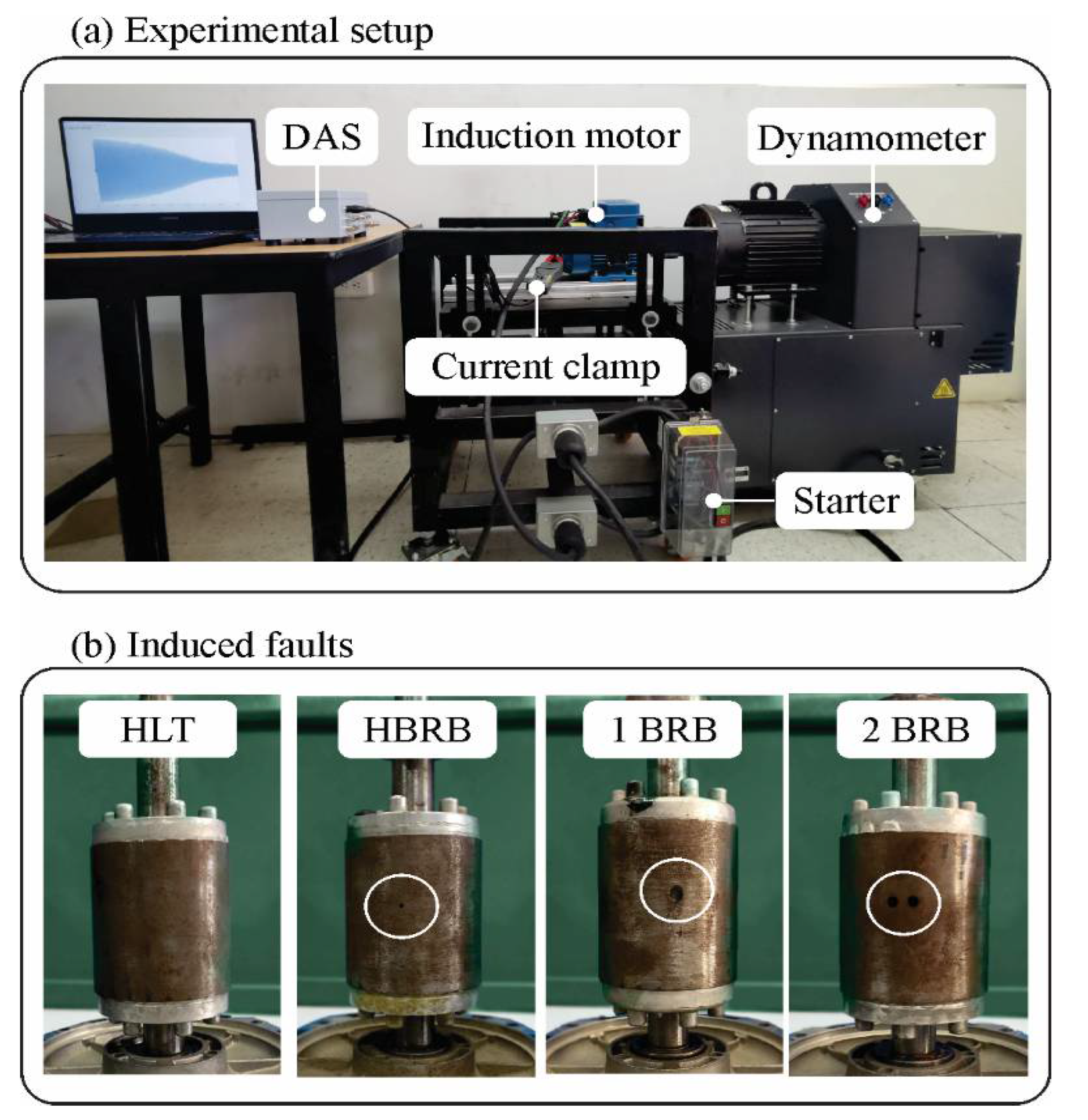
3. Experimental Setup

The BRB fault creates a particular behavior in the motor current during the start-up transient and steady-state response. In particular, in the IM start-up transient, time-varying frequency components appear in the current in the presence of a BRB fault [4]; similarly, fixed frequency components appear in the steady-state current when the IM is under a BRB fault [4]. For this reason, the proposed experimental setup considers monitoring the IM current in both regimes, start-up transient and steady-state, because both regimes provide relevant information about the IM condition. As shown in Figure 4a, the experimental setup includes a three-phase F-class IM model, WEG-00136APE48T. It is instrumented with a current clamp model (Fluke i200) for monitoring a single-phase current during the start-up transient and steady-state response. The motor characteristics are: 2 poles and 28 bars, 1 HP nominal power, 0.87 power factor, 3355 rev/min rated speed, and 2.9 A rated current (when the motor is fed with 230 VAC). The motor is fed by using a power source of 220 VAC at 60 Hz, and an 8540 dynamometer from LabVolt is employed for inducing 25% of the nominal load in the IM. The data acquisition is performed through a NI-USB 3211 from National Instruments with a setup of 1.5 kHz as the sampling rate and a time window of 8190 samples (5.46 s). The data acquisition system also has a passive resistor-capacitor (RC) low-pass filter with a cutoff frequency of 1500 Hz to avoid aliasing errors. The analyzed study cases are four: HLT, HBRB, 1BRB, and 2BRB, where 100 tests are performed in each case. As can be seen in Figure 4b, the damage in the rotor is induced by drilling a bar partially (HBRB), drilling a bar (1BRB), and drilling two adjacent bars (2BRB), respectively.

4. Results

Following the methodological steps, the HT is applied to the current signals, which include the start-up and steady-state regimes for the four induction motor conditions (healthy condition and half-, 1-, and 2-BRBs) in order to estimate their envelopes. Figure 5 shows the measured current signals for the four induction motor conditions (healthy condition and half-, 1-, and 2-BRBs) and their estimated envelopes, where the yellow and blue rectangles indicate the start-up transient and steady-state, respectively. According to this figure, it should be pointed out that significant patterns or differences among the analyzed IM conditions cannot be visually detected; hence, additional processing is required to identify suitable features in the measured current signals for associating them with the IM conditions.
Once the envelopes of the current signals are estimated, they are evaluated through PSO for identifying the start-up and steady-state regimes in order to analyze both states in a separate way, allowing a more flexible tool to diagnose the IM condition by employing the following two options: (1) To analyze the signal measured in one single regime in order to obtain the IM condition, or (2) to analyze both regimes and combine the obtained results in order to determine the IM condition in a more reliable manner according to the rules proposed in Section 2.3. Figure 6a illustrates an example of the sample number (denoted by a blue circle at the intersection point of both straight lines) estimated by PSO with the aim of dividing the monitored current signal into its two regimes: start-up and steady-state. Figure 6b depicts PSO convergence for determining the sample from which the acquired signal must be separated. Based on this figure, the PSO method allows one to correctly determine the sample (in this case, the sample number 3974 is identified) for dividing the acquired signals into their start-up transient and steady-state regimes.
The divided current signals are then used as inputs for two autoencoders (one to analyze the start-up transient regime and the other to analyze the steady-state) to identify suitable features in the analyzed signals, allowing the IM condition to be automatically determined. To reduce the computational complexity of autoencoders (i.e., the input size), a decimation stage is applied to the input signals. As the decimation factor is unknown, values from 2 to 6 are investigated. It is important to note that these values allow for a reduction in the number of samples while maintaining the frequency content related to the phenomenon under investigation [32]. Only for illustrative purposes, Figure 7 and Figure 8 show the original and decimated signals by using values from 2 to 6 for both regimes of the HLT condition, i.e., start-up transient and steady-state, respectively; in addition, their spectra estimated by Fourier are also included in order to demonstrate that the bandwidth of interest, i.e., the main frequency (60 Hz) and the interharmonic components around it, is not affected by the decimation stage, but with the benefit of reducing (1) the number of samples and, consequently, (2) the computational complexity of autoencoders. This stage also performs either padding or truncation of some samples of the input current signal in order to achieve the input size of the autoencoders when it does not match exactly with the input signal. This condition can occur since the analyzed current signal can present small differences between each running of the IM; therefore, the intersection point between the start-up transient and steady-state can slightly change, making their sizes change. In the tests carried out, the number of samples that have to be padded or truncated is between ±7 samples, which do not compromise the performance of the autoencoder.
After dividing and decimating the current signals, they are used to identify the most adequate quantity of neurons for the encoder stage, i.e., the M value in Figure 3a. This value allows establishing a trade-off between the accuracy for evaluating the IM condition and the computational complexity (i.e., the autoencoder size). In this regard, after an exhaustive analysis, a decimation value of 6 and 165 neurons for both autoencoders are identified as the most reliable values. The value of 165 corresponds to the output of the encoder stage and the input of the SoftMax layer for estimating the IM condition automatically (see Figure 3c). Hence, the final architecture for both autoencoders is 670 inputs (this value results from decimating the input signal, whether start-up transient or steady-state, with a factor of 6), 165 neurons at the encoder stage, and 4 outputs in the SoftMax, which correspond with the IM condition (healthy condition and half-, 1-, and 2-BRBs). Figure 9 presents the results achieved in the loss function when the autoencoders are trained, where it is possible to observe that the method converges after iteration 130 (denoted by a gray rectangle). It is important to mention that for performing the training and validation of both autoencoders, 70% and 30% of the data are used, respectively. Figure 10 illustrates the confusion matrices obtained for both regimes, without and with the decimation stage, respectively. From this figure, it is observed that the autoencoders without the decimation stage are not capable of identifying suitable patterns for differentiating among the different IM conditions during start-up transient and steady-state regimes since 82.5% and 91.7% of accuracy are reached, respectively. On the contrary, if the analyzed signals are decimated, the autoencoders assess the IM conditions in both regimes with 100% accuracy because a perfect match is obtained between the target class and the output class (see Figure 10b). As can be observed, the confusion matrices indicate that the IM condition is correctly classified since the 30 tests for each condition are found in the diagonal for both analyzed regimes (green rectangles in Figure 10b); in contrast, if one of the analyzed tests is off-diagonal, the values in the red rectangles would indicate that the IM condition is not correctly cataloged (e.g., from the 30 tests in the HRBR condition (see Figure 10a), 25 and 26 tests are correctly identified for each regime, but 5 and 4 tests were mistakenly cataloged with the 1BRB condition for each analyzed regime, respectively). As a result of these findings, it is possible to conclude that the decimation stage is useful for (1) reducing the computational complexity of the autoencoder and (2) improving accuracy during the evaluation of IM conditions because decimated signals concentrate in a smaller range of the frequency content related to the fault [32]. Further, it is worth noting that the decimation stage is initially used to identify the suitable size of the autoencoders; however, once this value is identified, the sampling frequency of the acquired signal can be adapted from the beginning.
Finally, to determine the IM condition in a more reliable way, the estimated results of both autoencoders are combined according to the previously established rules. Since the obtained results show 100% accuracy in each analyzed regime, the proposed expert system also has 100% accuracy, which does not increase the accuracy obtained by each autoencoder but strengthens the suitability of the result. Also, it should be pointed out that the proposed expert system attempts to be a general strategy that can be adapted and integrated into any other IM, mainly for larger motors where the fault can represent more dangerous and expensive situations. However, a proper calibration for the in-test motor has to be conducted since the amplitude of the current signal and the duration of the start-up transient change according to both the rated power of the motor and its mechanical load.

Discussion

Detection of incipient damages as HBRB (i.e., a partially cracked bar) is a challenging task because they are characterized by producing slight modifications to the IM operation as well as the measured signals. Hence, it is of great interest to propose expert systems, such as the one proposed in this work, which can correctly assess the IM condition under initial or incipient damages. In this regard, Table 1 compares the results obtained by the proposal with the latest expert systems-based methods described in the literature for the detection of BRBs in IM. In particular, it includes the techniques or methods employed in each proposal, the analyzed state, the fault severity, and the efficacy achieved for evaluating the IM condition.
According to Table 1, it is observed that the proposed expert system is capable of identifying the presence of BRBs in both states, i.e., start-up transient and steady-state, with high accuracy, starting from incipient BRBs and consolidating them, unlike other reported works in the literature, where they have only studied one regime and consolidated BRB faults [2,10,11]. However, in HBRB detection works [1,6,16], values greater than 90% accuracy are obtained, which is very promising. In particular, the method introduced in [1] presents 99% accuracy, which is obtained by integrating the HT and Gaussian probability density function to identify the presence of incipient faults in the IM using the start-up regime. Nonetheless, the method presented in this paper outperforms the accuracy of both regimes for assessing the IM condition, making it a more desirable method for the industry. Furthermore, it should be noted that the proposed method offers two significant attributes: (1) it presents an autoencoder-based methodology to identify diverse levels of automatically and accurately BRB severity, and (2) it uses directly the monitored current signals without the need of any domain transformation, allowing the generation of a solution of low computational complexity.

5. Conclusions

IMs are characterized by being the main electric machines used in industrial processes; evaluating their condition is therefore vital. In this regard, an expert system based on the integration of HT, PSO, and autoencoders is proposed in this work for detecting BRBs in both regimes (start-up transient and steady-state), starting from incipient to consolidated faults. Four IM conditions are studied in this work (healthy condition and half-, 1-, and 2-BRBs), where 100% accuracy is reached for all the evaluated cases, which demonstrates the capability of the proposed expert system for fault diagnosis in both regimes.
In summary, the stages of the described methodology were combined to build an expert system that can classify the different IM conditions analyzed in this work with 100% effectiveness. Each of the stages was carefully designed to determine the appropriate parameters to obtain the best performance. Initially, the HT is used to estimate the envelope of the acquired current signal; later, the PSO method is used to divide the measured signal into its start-up transient and steady-state components. The PSO performance allows the separation of the current signal by locating the intersection point in less than 100 iterations of the algorithm. Then, different decimation factors were analyzed, determining that the signal can be decimated with a value of 6 without losing the features associated with the different failure levels, so each signal was adjusted to 670 samples for its subsequent analysis. Also, it was determined that the autoencoder presents a good performance with 165 neurons, achieving its convergence in a maximum of 130 epochs. A comparison of the classifier performance for signals with and without decimation was accomplished; in the case of signals without decimation, 82.5% and 91.7% of accuracy were obtained for the analysis of the start-up and steady-state regimes, respectively. On the contrary, 100% effectiveness was obtained with the decimated signals in both regimes, thus reducing the computational load and improving the effectiveness.
It should be noted that the proposal can be considered a reliable tool for evaluating the IM condition in industrial processes because it only requires acquiring the IM current to automatically diagnose the BRB fault without interfering with the machine’s normal operation. In future work, other faults, e.g., bearing defects, unbalance, and short circuits, among others, as well as their combinations, will be evaluated or investigated for the purpose of developing and integrating a more general and robust expert system that evaluates the IM condition.

Author Contributions

Writing—review, writing—original draft preparation, and editing, all authors; methodology, M.V.-R., J.R.R.-G. and J.P.A.-S.; Conceptualization, J.P.A.-S. and M.V.-R.; visualization, resources, and investigation, G.I.P.-S., J.P.A.-S. and M.V.-R.; data curation, J.P.A.-S. and J.J.D.S.-P.; formal analysis, validation, and software, all authors; funding acquisition, J.R.R.-G. and G.I.P.-S.; project administration and supervision, M.V.-R. and J.P.A.-S. All authors have read and agreed to the published version of the manuscript.

Funding

This work was partially sponsored by Facultad de Ingeniería-Problemas Nacionales 2021 No., Project 202112.

Institutional Review Board Statement

Not applicable.

Informed Consent Statement

Not applicable.

Data Availability Statement

The data presented in this study are not publicly available due to privacy issues.

Conflicts of Interest

The authors declare no conflict of interest.

References

  1. Abd-el-Malek, M.; Abdelsalam, A.K.; Hassan, O.E. Induction motor broken rotor bar fault location detection through envelope analysis of start-up current using Hilbert transform. Mech. Syst. Signal Proc. 2017, 93, 332–350. [Google Scholar] [CrossRef]
  2. Martinez-Herrera, A.L.; Ferrucho-Alvarez, E.R.; Ledesma-Carrillo, L.M.; Mata-Chavez, R.I.; Lopez-Ramirez, M.; Cabal-Yepez, E. Multiple fault detection in induction motors through Homogeneity and Kurtosis computation. Energies 2022, 15, 1541. [Google Scholar] [CrossRef]
  3. Drakaki, M.; Karnavas, Y.L.; Karlis, A.D.; Chasiotis, I.D.; Tzionas, P. Study on fault diagnosis of broken rotor bars in squirrel cage induction motors: A multiagent system approach using inteligente classifiers. IET Electr. Power Appl. 2020, 14, 245–255. [Google Scholar] [CrossRef]
  4. Amezquita-Sanchez, J.P.; Valtierra-Rodriguez, M.; Perez-Ramirez, C.A.; Camarena-Martinez, D.; Garcia-Perez, A.; Romero-Troncoso, R.J. Fractal dimension and fuzzy logic systems for broken rotor bars detection in induction motors at start-up and steady-state. Meas. Sci. Technol. 2017, 28, 075001. [Google Scholar] [CrossRef]
  5. Tahkola, M.; Szucs, A.; Halme, J.; Zeb, A.; Keranen, J. A Novel Machine Learning-Based Approach for Induction Machine Fault Classifier Development—A Broken Rotor Bar Case Study. Energies 2022, 15, 3317. [Google Scholar] [CrossRef]
  6. Rivera-Guillen, J.R.; De Santiago-Perez, J.J.; Amezquita-Sanchez, J.P.; Valtierra-Rodriguez, M.; Romero-Troncoso, R.J. Enhanced FFT-based method for incipient broken rotor bar detection in induction motors during the startup transient. Measurement 2018, 124, 277–285. [Google Scholar] [CrossRef]
  7. Kafeel, A.; Aziz, S.; Awais, M.; Khan, M.A.; Afaq, K.; Idris, S.A.; Alshazly, H.; Mostafa, S.M. An expert system for rotating machine fault detection using vibration signal analysis. Sensors 2021, 21, 7587. [Google Scholar] [CrossRef]
  8. Seera, M.; Lim, C.P.; Nahavandi, S.; Loo, C.K. Condition monitoring of induction motors: A review and an application of an ensemble of hybrid intelligent models. Expert Syst. Appl. 2014, 41, 4891–4903. [Google Scholar] [CrossRef]
  9. Asad, B.; Vaimann, T.; Belahcen, A.; Kallaste, A.; Rassolkin, A.; Iqbal, M.N. Broken rotor bar fault detection of the grid and inverter-fed induction motor by effective attenuation of the fundamental component. IET Electr. Power Appl. 2019, 13, 2005–2014. [Google Scholar] [CrossRef]
  10. Burriel-Valencia, J.; Puche-Panadero, R.; Martinez-Roman, J.; Sapena-Bano, A.; Pineda-Sanchez, M.; Perez-Cruz, J.; Riera-Guasp, M. Automatic fault diagnostic system for induction motors under transient regime optimized with expert systems. Electronics 2018, 8, 6. [Google Scholar] [CrossRef]
  11. Navarro-Navarro, A.; Zamudio-Ramirez, I.; Biot-Monterde, V.; Osornio-Rios, R.A.; Antonino-Daviu, J.A. Current and stray flux combined analysis for the automatic detection of rotor faults in soft-started induction motors. Energies 2022, 15, 2511. [Google Scholar] [CrossRef]
  12. Misra, S.; Kumar, S.; Sayyad, S.; Bongale, A.; Jadhav, P.; Kotecha, K.; Abraham, A.; Gabralla, L.A. Fault detection in induction motor using time domain and spectral imaging-based transfer learning approach on vibration data. Sensors 2022, 22, 8210. [Google Scholar] [CrossRef] [PubMed]
  13. Liu, X.; Yan, Y.; Hu, K.; Zhang, S.; Li, H.; Zhang, Z.; Shi, T. Fault diagnosis of rotor broken bar in induction motor based on successive variational mode decomposition. Energies 2022, 15, 1196. [Google Scholar] [CrossRef]
  14. Atta, M.E.E.-D.; Ibrahim, D.K.; Gilany, M.A. Broken bar faults detection under induction motor starting conditions using the optimized Stockwell Transform and adaptive time-frequency filter. IEEE Trans. Instrum. Meas. 2021, 70, 3518110. [Google Scholar]
  15. Lopez-Ramirez, M.; Ledesma-Carrillo, L.M.; Garcia-Guevara, F.M.; Munoz-Minjarez, J.; Cabal-Yepez, E.; Villalobos-Pina, F.J. Automatic early broken-rotor-bar detection and classification using otsu segmentation. IEEE Access 2020, 8, 112624–112632. [Google Scholar] [CrossRef]
  16. Morales-Perez, C.; Rangel-Magdaleno, J.; Peregrina-Barreto, H.; Amezquita-Sanchez, J.P.; Valtierra-Rodriguez, M. Incipient broken rotor bar detection in induction motors using vibration signals and the orthogonal matching pursuit algorithm. IEEE Trans. Instrum. Meas. 2018, 67, 2058–2068. [Google Scholar] [CrossRef]
  17. Li, H.; Feng, G.; Zhen, D.; Gu, F.; Ball, A.D. A normalized frequency domain energy operator for broken rotor bar fault diagnosis. IEEE Trans. Instrum. Meas. 2020, 70, 3500110. [Google Scholar] [CrossRef]
  18. Fernandez-Cavero, V.; Pons-Llinares, J.; Duque-Perez, O.; Morinigo-Sotelo, D. Detection of broken rotor bars in nonlinear startups of inverter-fed induction motors. IEEE Trans. Ind. Appl. 2021, 57, 2559–2568. [Google Scholar] [CrossRef]
  19. Panagiotou, P.A.; Arvanitakis, I.; Lophitis, N.; Antonino-Daviu, J.A.; Gyftakis, K.N. A new approach for broken rotor bar detection in induction motors using frequency extraction in stray flux signals. IEEE Trans. Ind. Appl. 2019, 55, 3501–3511. [Google Scholar] [CrossRef] [Green Version]
  20. Ferrucho-Alvarez, E.R.; Martinez-Herrera, A.L.; Cabal-Yepez, E.; Rodriguez-Donate, C.; Lopez-Ramirez, M.; Mata-Chavez, R.I. Broken rotor bar detection in induction motors through contrast estimation. Sensors 2021, 21, 7446. [Google Scholar] [CrossRef]
  21. Messaoudi, M.; Flah, A.; Alotaibi, A.A.; Althobaiti, A.; Sbita, L.; El-Bayeh, C.Z. Diagnosis and fault detection of rotor bars in squirrel cage induction motors using combined Park’s vector and extended Park’s vector approaches. Electronics 2022, 11, 380. [Google Scholar] [CrossRef]
  22. Lee, C.-Y.; Wen, M.-S.; Zhuo, G.-L.; Le, T.-A. Application of ANN in induction-motor fault-detection system established with MRA and CFFS. Mathematics 2022, 10, 2250. [Google Scholar] [CrossRef]
  23. Guajardo, L.A.T.; Garza, M.A.P.; Maldonado, J.R.; Vazquez, M.A.G.; Alfaro, L.H.R.; Salinas, F.S. Prony method estimation for motor current signal analysis diagnostics in rotor cage induction motors. Energies 2022, 15, 3513. [Google Scholar] [CrossRef]
  24. Feldman, M. Hilbert transform in vibration analysis. Mech. Syst. Signal Proc. 2011, 25, 735–802. [Google Scholar] [CrossRef]
  25. Amezquita-Sanchez, J.P.; Park, H.S.; Adeli, H. A novel methodology for modal parameters identification of large smart structures using MUSIC, empirical wavelet transform, and Hilbert transform. Eng. Struct. 2017, 147, 148–159. [Google Scholar] [CrossRef]
  26. Mezura-Montes, E.; Coello, C.A.C. Constraint-handling in nature-inspired numerical optimization: Past, present and future. Swarm Evol. Comput. 2011, 1, 173–194. [Google Scholar] [CrossRef]
  27. Marini, F.; Walczak, B. Particle swarm optimization (PSO). A tutorial. Chemom. Intell. Lab. Syst. 2015, 149, 153–165. [Google Scholar] [CrossRef]
  28. Lee, C.Y.; Cheng, Y.H. Motor fault detection using wavelet transform and improved PSO-BP neural network. Processes 2020, 8, 1322. [Google Scholar] [CrossRef]
  29. Du, B.; Xiong, W.; Wu, J.; Zhang, L.; Zhang, L.; Tao, D. Stacked convolutional denoising auto-encoders for feature representation. IEEE Trans. Cybern. 2016, 47, 1017–1027. [Google Scholar] [CrossRef]
  30. Liu, P.; Zheng, P.; Chen, Z. Deep learning with stacked denoising auto-encoder for short-term electric load forecasting. Energies 2019, 12, 2445. [Google Scholar] [CrossRef] [Green Version]
  31. Agarwala, A.; Pennington, J.; Dauphin, Y.; Schoenholz, S. Temperature check: Theory and practice for training models with softmax-cross-entropy losses. arXiv 2020, arXiv:2010.07344. [Google Scholar]
  32. Romero-Troncoso, R.J.; Garcia-Perez, A.; Morinigo-Sotelo, D.; Duque-Perez, O.; Osornio-Rios, R.A.; Ibarra-Manzano, M.A. Rotor unbalance and broken rotor bar detection in inverter-fed induction motors at start-up and steady-state regimes by high-resolution spectral analysis. Electr. Power Syst. Res. 2016, 133, 142–148. [Google Scholar] [CrossRef]
Figure 1. Expert system methodology for induction motor diagnosis.
Machines 11 00156 g001
Figure 2. PSO-based strategy for regime separation.
Machines 11 00156 g002
Figure 3. (a) Autoencoder structure; (b) SoftMax structure; and (c) Proposed classification structure.
Machines 11 00156 g003
Figure 4. (a) Experimental setup and (b) rotor conditions.
Machines 11 00156 g004
Figure 5. (a) Measured current signals for the analyzed IM conditions and (b) their estimated envelopes.
Machines 11 00156 g005
Figure 6. (a) The sample estimated by PSO for dividing both regimes and (b) the convergence of PSO.
Machines 11 00156 g006
Figure 7. (a) Original and decimated current signals obtained using the start-up regime, and (b) their spectrums estimated by Fourier transform.
Machines 11 00156 g007
Figure 8. (a) Original and decimated current signals obtained using the steady-state regime and (b) their spectrums estimated by Fourier transform.
Machines 11 00156 g008
Figure 9. Obtained loss for autoencoders training.
Machines 11 00156 g009
Figure 10. Confusion matrices for the analyzed current signal in both regimes (a) without and (b) with decimation stage.
Machines 11 00156 g010
Table 1. Qualitative comparison between the proposed expert system and recent approaches introduced in the literature.
WorkMethodAnalyzed RegimeDetected FaultAccuracy Rate (%)
Burriel-Valencia et al. [10]
  • Fourier transform and harmonic order tracking analysis are employed for extracting features.
  • Support vector machine and a neural network are utilized for classifying the extracted patterns.
Start-up and Steady-state regimes1 BRB98.89
Morales-Perez et al. [16]
  • Orthogonal machine pursuit method and Fourier method are utilized for extracting features.
  • Tree decision algorithm is utilized for classifying the extracted patterns.
Steady-state regimeHBRB and 1BRB90
Abd-el-Malek et al. [1]
  • HT is employed for pattern extraction.
  • Gaussian distribution is employed for classifying the extracted patterns.
Start-up regimeHBRB and 1BRB99
Navarro-Navarro et al. [11]
  • Signal transformation is performed by Fourier transform.
  • Statistical methods are employed for feature extraction.
  • Neural networks are used for feature classification.
Start-up regime1 and 2 BRB94.4
Rivera-Guillen et al. [6]
  • Signal decomposition is performed by a STFT-based algorithm.
  • A weight function is employed for component extraction.
  • Index-based measurement is employed to classify the extracted component.
Start-up regimeHBRB, 1BRB, and 2BRB97.5
Martinez-Herrera et al. [2]
  • Homogeneity and kurtosis are employed for feature extraction.
  • Artificial neural network is employed for classifying the extracted patterns.
Start-up regime1BRB and 2BRB100
Proposed work
  • HT and PSO are employed for dividing the regimes acquired.
  • Decimation and autoencoders are employed for pattern extraction and classification.
Start-up and steady-state regimesHBRB, 1BRB, and 2BRB100
Disclaimer/Publisher’s Note: The statements, opinions and data contained in all publications are solely those of the individual author(s) and contributor(s) and not of MDPI and/or the editor(s). MDPI and/or the editor(s) disclaim responsibility for any injury to people or property resulting from any ideas, methods, instructions or products referred to in the content.

