Article

Thermal Elastohydrodynamic Analysis of a Worm Gear

1
Gear Research Center (FZG), Department of Mechanical Engineering, School of Engineering & Design, Technical University of Munich, Boltzmannstraße 15, 85748 Garching near Munich, Germany
2
Division of Machine Elements, Luleå University of Technology, 97187 Luleå, Sweden
*
Author to whom correspondence should be addressed.
Machines 2023, 11(1), 89; https://doi.org/10.3390/machines11010089
Submission received: 21 November 2022 / Revised: 4 January 2023 / Accepted: 5 January 2023 / Published: 10 January 2023
(This article belongs to the Special Issue Elastohydrodynamic Lubrication)

Abstract

:
This study explores the elastohydrodynamic lubrication (EHL) between the contacting tooth flanks of a worm gear with nonconjugate meshing action. The contact is characterized by a slender-like elliptical shape and high sliding. The geometry and contact conditions for the considered worm gear were obtained using tooth contact analysis. Based on that, the complete area of the worm gear contact was analyzed using a validated numerical EHL model considering non-Newtonian, thermal, and transient effects. The geometrical and kinematic design factors that influence EHL film formation in worm gears were identified and discussed. The results show the specific characteristics of worm gear EHL contacts, such as the very slender contact in the tooth root flank area, which diminishes the effect of the entrainment speed on film thickness. EHL film formation could be supported by increasing conformity between the flanks to make the contact less slender. By comparing the film thickness results against analytically obtained ones, relatively large differences were observed except for one formula for minimum film thickness.

1. Introduction

Worm gears have a wide application in industry. They allow large gear ratios up to 300:1 in a single gear stage. They can transfer motion through a 90° axis angle, have a compact design, are quiet in operation, and are typically self-locking, which prevents back-driving [1]. As such, they are used in industrial machinery, heavy equipment, and even in the consumer industry for applications, such as elevators, conveyor belts, lifting machines, presses, and ship steering systems [1,2].
Worm gears are typically manufactured by a machining process called hobbing. In this process, the cutting hob for the wheel can be nominally of the same size or slightly oversized than the cutting hob for the worm. Theoretically, under zero load conditions, the contact between these two cases differs. When a wheel hob is not oversized, the meshing action is conjugate, and the contact between the teeth flanks occurs in a line [2,3,4]. When a wheel hob is oversized, the meshing action is nonconjugate, and the contact occurs at a point [2,3,4]. To support lubricant film formation and prevent edge contacts, usually, an oversized wheel hob is used [2]. The following explanations and references are focused on this type of worm gears.
Under the influence of load, the point contact develops an elliptical contact area [4]. Depending on the direction of lubricant entrainment, elliptical contacts are generally divided into wide and narrow or so-called slender contacts. In wide elliptical contacts, the main lubricant entrainment direction coincides with the minor axis of the contact ellipse. In slender elliptical contacts, the main lubricant entrainment direction coincides with the major axis of the contact ellipse. Depending on the meshing position in worm gears, the main lubricant entrainment direction in the contact is at a low angle or fully coincides with the major axis of the contact ellipse. Hence, worm gears are characterized by slender-like elliptical contacts.
Worm gear contacts are also characterized by high sliding between contacting gear teeth. This results in high heat generation and relatively high power losses [1]. Wear is unavoidable in the worm gear contact and particularly important during the running-in phase [1]. Usually, a softer material, typically bronze or plastic, is used for the wheel so that it can wear out sooner and prolong service life.
One of the first people to analyze worm gear EHL contacts was Simon in 1997 [3]. He investigated the EHL film formation in a worm gear by solving the Reynolds, energy, elasticity, and Laplace equations. The performance characteristics of the considered worm gear were analyzed and compared. In 2001, Sharif et al. [5,6] used a modified Reynolds equation to simulate the EHL worm gear contact by considering the non-Newtonian behavior and thermal effects. The surface temperature was calculated by using a one-dimensional heat conduction equation. The tooth normal load was chosen to give the desired contact pressure. Additionally, the authors performed an elastic solid contact analysis with the aim of characterizing the dry contact between the flanks. The authors discovered poor oil film formation capability due to unfavorable heat convection to the primary inlet by gear flanks, which significantly decreases oil viscosity in the inlet zone. In 2006, the same authors developed a wear model of the worm gear contact based on the extended Archard’s wear law coupled with the Reynolds equation to account for pressure and film thickness variations over the contact area [7]. The model could calculate the wear rate, and it is highly affected by the considered relation between film thickness and wear rate. In 2012, Magyar [8] presented a calculation model for the local coefficient of friction of worm gears operating under mixed lubrication. The tooth flanks were discretized by substituting them with a set of rollers at discretized points along meshing positions. The minimum film thickness calculation was based on Venner’s formula for EHL line contacts [9]. The authors validated their calculations with experimental measurements on a worm gear test rig. Oehler et al. [10] built on the calculation model of Magyar to develop a simulation method for the efficiency and heat balance of worm gear drives.
The literature review shows that more than two decades have passed since a detailed EHL analysis of worm gears [5,6] was performed. In the meantime, the capability and accuracy of numerical modeling have improved. As industry aims at increasing power density and efficiency, EHL simulation models are an important method to aid the understanding and development of worm gears. This work demonstrates a numerical model for EHL worm gear contacts by using a state-of-the-art FEM model with fully coupled governing equations, considering non-Newtonian, thermal, and transient effects. The most influencing contact conditions on EHL film thickness formation are identified and discussed in terms of existing knowledge on slender EHL contacts. The computed film thickness is compared against established analytical approaches.

2. Methods

This section describes the object of investigation and the tooth contact analysis to obtain contact conditions across the area of gear contact. Furthermore, the main equations of the numerical EHL model of worm gear contacts are explained.

2.1. Object of Investigation

A standard reference worm gear pair of the common ZI type is considered, where the worm is an involute helicoid [2]. The center distance of the considered pair is a = 100   mm , and the gear ratio is i = 20.5 . A torque of T 2 = 400   Nm , rotational speed of n 1 = 2000   min 1 , and oil temperature of ϑ o i l = 65   are specified as input conditions. The lubricant used is polyglycol gear oil PG460, also used in previous worm gear EHL analyses [2,5,6,7,10]. The worm gear geometry and operating conditions, as well as solid material and oil properties, are listed in Table 1.

2.1.1. Tooth Contact Analysis

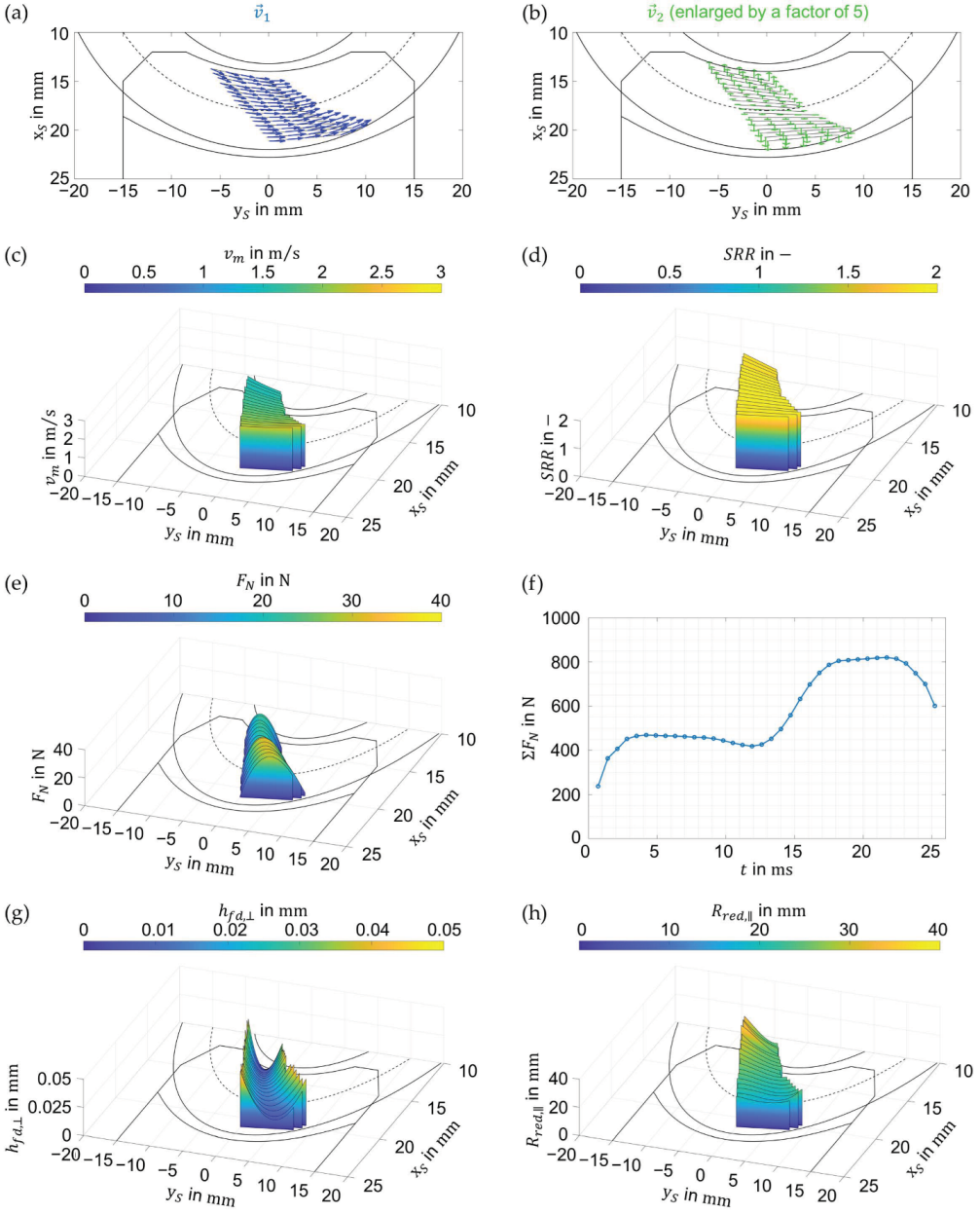
Geometries of the contacting tooth flanks, velocities, and load distributions for each meshing position across the area of gear contact are obtained from a tooth contact analysis (TCA) by the worm gear software SNETRA [12,13,14]. SNETRA data are transformed from the coordinate system of SNETRA ( x S ,   y S ,   z S ) to the coordinate system of the numerical EHL model ( x ,   y ,   z ). Figure 1 illustrates the considered worm gear and the schematic contact pattern or area of gear contact. As Figure 1c shows, the contact pattern develops from the tooth tip to the tooth root. Oil is entrained from inlet to outlet side.
Figure 2 shows the contact conditions for each meshing position across the area of gear contact obtained from SNETRA. These include the velocity vectors v 1 and v 2 of the worm and wheel, entrainment speed v m = ( v 1 + v 2 ) / 2 with v i = 1 , 2 = v i , x 2 + v i , y 2 , slide-to-roll ratio S R R = ( v 1 v 2 ) / v m , normal force F N and sum of the normal force F N , flank distance in the direction parallel to the meshing position h f d , , and reduced radius of curvature in the transverse direction to the meshing position R r e d , . In total, 36 meshing positions were analyzed.
The TCA in SNETRA assumes that there are numerous points of contact along each meshing position. With the help of the general approaches of analytical geometry, the points of contact between the flanks are replaced by an equivalent contact of a pair of rollers that rotate relative to each other in the transverse direction to the meshing position [8,10]. The reduced radius of curvature ( R r e d , ) of the pair of rollers corresponds to the geometry of the contacting flanks in the mentioned direction. This simplification also allows applying an analytical formula for minimum film thickness calculation, which will be compared to the minimum film thickness results from this study in Section 3.3.
An oversized cutting hob for the wheel results in a nonconjugate meshing action. The number of teeth considered in the calculation of the contact pattern is determined by the contact ratio ϵ , referring to the number of engaged teeth within one meshing position. The scattered data of the geometries and velocities are smoothed by fitting high-order polynomials. The scattered data of load are integrated along each meshing position to obtain the integral load value. The center of the coordinate system of the numerical EHL model ( x ,   y ,   z ) is placed at the location of h f d , minimum at each meshing position, as illustrated in Figure 1c.

2.1.2. Implementation of Contact Conditions in EHL Model

Figure 2a,b show that the magnitude and direction of the velocity vectors v 1 and v 2 of the worm and wheel vary across the area of gear contact. In order to take this into account in the numerical EHL model (see Section 2.2), after interpolation of the scattered data, velocity fields from SNETRA are implemented in the EHL model by determining the velocity in the parallel and transverse directions to the meshing position; v i , x = v i , = f ( x , t ) , and v i , y = v i , = f ( x , t ) , where i = ( 1 , 2 ) .
The worm and wheel flank are geometrically characterized as double-curved surfaces, which means that they have curvature in tooth height and width direction. For the sake of saving computational effort, the contact between the tooth flanks is transferred to an equivalent contact between a rigid ellipsoid and an elastic body, as performed for hypoid gears in [15]. In the equivalent contact, the radius of curvature of the rigid ellipsoid in the y -direction is described by the function R r e d , y = R r e d , = f ( x , t ) , while the curvature of the rigid ellipsoid in the x -direction is described by the flank distance curvature h f d , x = h f d , = f ( x , t ) (see Figure 2g). The undeformed gap between the rigid ellipsoid and the elastic body in the dimensional form can therefore be expressed as:
g ( x , y , t ) = h f d , x ( x , t ) + y 2 2 R r e d , y ( x , t )
The elastic properties of the contacting tooth flanks are taken into consideration through the equivalent modulus of elasticity E e q and equivalent Poisson’s ratio ν e q , whose definitions can be found in [15].

2.1.3. Solid Contact Analysis

Since the shape of the rigid ellipsoid in the equivalent contact is not described by two radii of curvatures but by the flank distance in the x -direction h f d , x ( x , t ) and the radius of curvature in the y -direction R r e d , y ( x , t ) , simple Hertzian equations cannot be applied for the determination of the dry contact area. Therefore, a state-of-the-art contact mechanics numerical model developed by Almqvist and his team [16] is used. The contact mechanics model is based on continuous convolution fast Fourier transform (CC–FFT) and a variational principle.
The accuracy of the model was verified against Hertzian analytical equations for point contacts. The sensitivity of the solution to mesh size was tested for three mesh resolutions N x = N y = { 256 ,   512 ,   1054 } at the most loaded meshing position ( t = 22.41   ms ). The maximum solid contact pressure p s , m a x for the three considered mesh resolutions was p s , m a x = { 635.67 ,   634.22 ,   633.44 }   M P a . Because p s , m a x results converge with a difference around 0.12   % , the mesh with N x = N y = 1054 elements is used for the solid contact analysis.

2.2. Thermal Elastohydrodynamic Lubrication Model

In the following section, the governing equations are presented, followed by the dimensionless formulation and the introduction of equations that describe lubricant properties. Finally, the numerical implementation into a finite element model (FEM) is presented.

2.2.1. Governing Equations

To determine the fluid flow, the generalized Reynolds equation for point contacts with bidirectional oil entrainment is solved, which reads [17]:
x ( ε p f x ) y ( ε p f y ) + ρ x * x + ρ y * y + ρ e t + ξ p f Θ ( p f ) penalty term = 0 ,
where
ε = η e η e ρ ρ ,   ρ = z 1 z 2 ρ z 1 z d z η d z ,   ρ = z 1 z 2 ρ z 1 z z d z η d z , ρ x * = ρ e v 1 , x + η e v g , x ρ ,   ρ y * = ρ e v 1 , y + η e v g , y ρ , 1 η e = z 1 z 2 d z η ,   1 η e = z 1 z 2 z d z η   and   ρ e = z 1 z 2 ρ d z .
Cavitation problem is treated by adding the penalty term to the Reynolds equation. The corresponding velocity and shear stress field components are defined by Equations (3) and (4) [17]:
v f , x = v 1 , x + p f x ( z 1 z z d z η η e η e z 1 z d z η ) + η e v g , x z 1 z d z η , v f , y = v 1 , y + p f y ( z 1 z   z d   z η η e η e z 1 z d   z η ) + η e v g , y z 1 z d   z η ,
τ f , zx = z p f x + τ zx 0   with   τ zx 0 = τ zx 0 ( z = 0 )   and   z 1 z 2 z p f x + τ zx 0 η d z = v 2 , x v 1 , x , τ f , zy = z p f y + τ zy 0   with   τ zy 0 = τ zy 0 ( z = 0 )   and   z 1 z 2 z p f y + τ zy 0 η d z = v 2 , y v 1 , y .
The energy equations for fluids and solids are defined by Equations (5) and (6), respectively:
x ( λ T x ) + y ( λ T y ) + z ( λ T z ) ρ c p ( v f , x T x + v f , y T y ) T ρ ρ T ( v f , x p f x + v f , y p f y ) + η [ ( v f , x z ) 2 + ( v f , y z ) 2 ] = ρ c p T t ,
x ( λ i T x ) + y ( λ i T y ) + z ( λ i T z ) ρ i c p , i ( v i , x T x + v i , y T y ) = ρ i c p , i T t
where i = 1,2.
The film thickness equation reads:
h ( x , y , t ) = h 0 ( t ) + g ( x , y , t ) + δ ( t ) ,
where g ( x , y , t ) is the geometry of the undeformed gap defined in Equation (1).
The elastic deformation of an equivalent body is obtained by solving the linear elasticity equation, which reads:
· σ = 0 ,   σ = C · ε ( U ) ,   U = ( u x u y u z ) ,   δ = u z .
The applied load and generated fluid pressure are balanced in each time step using the load balance equation, which reads:
Ω P p f ( x , y , t ) d x d y = F N ( t ) .

2.2.2. Dimensionless Formulation

The following set of dimensionless parameters is used to transform the governing equations in the dimensionless form [17]:
X = x a x ,   Y = y a y ,   Z = { solids : z a x   fluid :   z h H = h R r e d , x 0 a x 2 ,   U X = u x R r e d , x 0 a x 2 ,   U Y = u y R r e d , x 0 a x 2 ,   U Z = u z R r e d , x 0 a x 2 ,   δ ¯ = δ R r e d , x 0 a x 2 t ¯ = t v m , 0 a x ,   P = p f p H , m a x   ,   T ¯ = T T 0 ,   ρ ¯ = ρ ρ 0 ,   η ¯ = η η 0   and   τ ¯ = τ p H , m a x  
The radius of curvature in the x -direction at the contact center R r e d , x 0 ( x = 0 , t ) is determined from the flank distance h f d , x ( x = 0 , t ) (see Figure 2g) by applying the formula for radius of curvature that reads:
R r e d , x 0 ( x = 0 , t ) = | ( 1 + ( h f d , x ( x = 0 , t ) ) 2 ) 3 2 ( h f d , x ( x = 0 , t ) ) |
The parameters R r e d , x 0 ( x = 0 , t ) and v m , 0 ( x = 0 , y = 0 , t ) are evaluated at the contact center for each time step, and the mean values over the considered time period are chosen for the dimensionalization. In the same way, the maximum value of the normal force F N ( t ) over the considered time period is used to calculate the time-independent dimensionless Hertzian parameters, a x and a y . In this way, in each time step, the contact area in the X - and Y -direction is within ~ ( 1.0 ,   1.0 ) . A similar strategy was applied in [18].
The time step between two meshing positions is constant. The choice of the time step size t is based on the following relationship:
t = t E f t n E
where t E is the meshing time of a single tooth of the worm gear, calculated as:
t E = 60 n 2 z 2 ϵ
The number of considered meshing positions n E = 36 is obtained from the TCA in SNETRA. The factor f t in Equation (12) determines the number of interpolated meshing positions between two meshing positions as obtained from the TCA. The factor f t was varied in the range f t = { 3 , 6 , 9 } , and no major change in the results was noticed for the considered range of f t . A value of f t = 9 is used in this study, resulting in the time step size of t = 0.0778   ms and a total of 370 time steps.

2.2.3. Lubricant Equations

The effects of pressure and temperature on oil viscosity μ ( p f , T ) are modeled by an improved Yasutomi temperature–pressure–viscosity correlation [19] that reads:
μ ( p f , T ) = μ g   exp [ 2.303 C 1 ( T T g ) F C 2 + ( T T g ) F ] ,
where
T g ( p f ) = T g 0 + A 1 ln ( 1 + A 2 p f ) ,   and   F ( p f ) = ( 1 + b 1 p f ) b 2 .
The parameters used in Equation (14) are fitted to the experimentally measured low-shear viscosity at the elevated pressure of up to p f = 1.2   GPa and three temperatures   ϑ o i l = { 40 ,   65 ,   100 }   , published in [20].
A multicomponent modified Carreau model for mixtures [20] describes the influence of the shear stress on the oil viscosity η ( τ ) , as follows:
η ( p f , T , τ ) = μ ( p f , T ) i = 1 N f i [ 1 + ( τ G i ) 2 ] ( 1 1 n c , i ) 2 ,   i = 1 N f i = 1
The density of the oil ρ ( p f , T ) is described by the Dowson–Higginson model [21], improved by Bos [22], which reads:
ρ ( p f , T ) = ρ 0 ( 1 + D 1 p f 1 + D 2 p f ) [ 1 ε ( T T 0 ) ] ,
where
ε = ε 0 exp ( λ ρ p f ) .
The thermal conductivity and specific heat capacity per volume are described by the models of Larsson and Andersson for polyglycol oils [23]:
λ ( p f ) = λ 0 ( 1 + d λ 1 p f 1 + d λ 2 p f ) ,
( c p ρ ) ( T , p f ) = ( c p ρ ) ( 295   K ) ( 1 + A c 1 p f 1 + A c 2 p f ) [ 1 + A c 3 ( 1 + A c 4 p f + A c 5 p f 2 )   ( T 295   K ) ] .
The parameters for modeling properties of the considered oil PG460 (see Table 1) are listed in Table 2.

2.2.4. Numerical Modeling

The numerical EHL model is based on Habchi’s full-system approach [17] and the work of Ziegltrum et al. [24]. It is an extension of the FEM model of the authors in [25], where it was validated for slender thermal EHL contacts operating under a wide range of entrainment speeds and slide-to-roll ratios ( S R R s). Additionally, the sensitivity of the solution on mesh resolution was checked in [25].
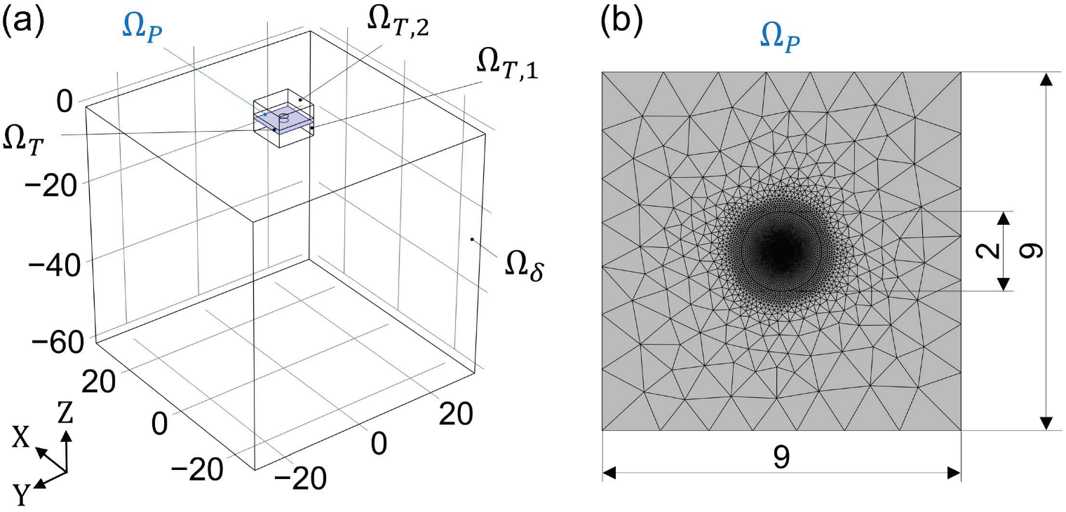
Figure 3 shows the dimensionless calculation domains (a) and the meshed fluid domain (b) of the numerical EHL model. The generalized Reynolds equation is solved in the two-dimensional domain Ω P , while the energy equations for fluids and solids are solved in the three-dimensional domains Ω T , Ω T , 1 , and Ω T , 2 . The elastic deformation of an equivalent body is computed in the three-dimensional computational domain Ω δ . The pressure field obtained from the Reynolds equation is mapped in the gap height direction. The shear stress distribution in the gap height direction is solved by the shear stress distribution over the two-dimensional oil film domain, and the oil property variations with pressure, temperature, and shear stress over the entire oil film domain are thus obtained.
.
Triangular and tetrahedral elements are used for the domains Ω P , Ω δ , Ω T , 1 , and Ω T , 2 . For Ω P , a finer mesh is used in the regions where high-pressure gradients are expected to occur, that is, within the contact area (see Figure 3b). Additionally, a fine mesh within the contact area improves interpolation of the TCA input data of SNETRA. In the gap height direction, uniformly distributed prism elements are used, which speeds up the computation of the integral terms [17]. A fine mesh with a total of n e = 104 , 705 elements is used. In the validating work [25], where model symmetry was employed due to unidirectional entrainment, it was found that convergence of the solution was fully achieved at n e = 51 , 356 . Hence, it can be concluded that the results of the current model are independent of the mesh resolution.

3. Results and Discussion

The first part of the section shows the reference results from a dry contact analysis. The second part shows the results from the EHL contact analysis. This is followed by a classification of the film thickness results into established analytical approaches. Note that the results shown in this section were obtained with the coordinate system of the numerical EHL model ( x ,   y ,   z ) and then transformed back to the coordinate system of SNETRA ( x S ,   y S ,   z S ).

3.1. Dry Contact Analysis

The reference results from the dry contact analysis, according to Section 2.1.3, are shown in Figure 4. Figure 4a shows the computed dry contact area for each meshing position of a meshing cycle. From these results, the ellipticity ratio k = a y a x was calculated and is plotted in Figure 4b against the radii of curvatures R r e d , x 0 and R r e d , y 0 , evaluated at the center of the equivalent contact.
Figure 4a shows that the dry contact area between the contacting tooth flanks has an elliptical shape, which becomes more elongated and slenderer toward the tooth root of the wheel, as k reduces. This is due to the increase in conformity between the flanks in the x -direction (see Figure 2g and R r e d , x 0 in Figure 4b), as well as the decrease in the radius of curvature in the y -direction (see Figure 2h and R r e d , y 0 in Figure 4b). The increase in the dry contact area is mainly caused by the increase in load over the meshing cycle.
The results from the dry contact analysis show the influence of geometry and load on the shape and extent of the dry contact area between the contacting flanks. This supports a deeper understanding of the results of the EHL contact analysis, presented in the following section.

3.2. EHL Contact Analysis

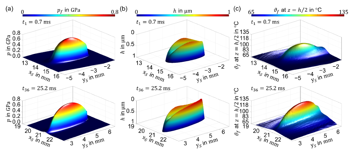
Exemplary results from the EHL contact analysis, according to Section 2.2, are presented in Figure 5. Thereby, three-dimensional surface plots of fluid pressure p f , film thickness h , and fluid temperature ϑ f at z = h 2 are shown for two meshing positions at t 1 = 0.7   ms and t 36 = 25.2   ms . The meshing position at t 1 is the closest meshing position to the tooth tip of the wheel, while the meshing position at t 36 is the closest one to the tooth root of the wheel.
Figure 5 shows that the EHL contact is slenderer in the tooth root flank area ( t 36 ) than in the tooth tip flank area ( t 1 ), which corresponds to the results of the dry contact analysis (see Section 3.1). Figure 5a shows a higher fluid pressure p f in the tooth root flank area. Figure 5b indicates an asymmetrical distribution of the film thickness h , as it is different in the side lobes. From Figure 5c, it can be observed that ϑ f at z = h 2 is higher in the tooth root flank area, which is a sign of more severe conditions in this part of the meshing cycle.
Figure 6 shows the contours of fluid pressure p f , film thickness h , and fluid velocity v f at z = h 2 for eight positions of the meshing cycle. The contour of the dry contact area obtained in Section 3.1 was added to the contour plots of p f and v f .
From the fluid pressure contours p f shown in Figure 6a, the EHL-pressurized area closely matches the dry contact area in the tooth tip flank area. In the tooth root flank area, the difference between the EHL-pressurized area and the dry contact area is larger. The difference occurs because the EHL-pressurized area is not only affected by the tooth flank geometry ( h f d , and R r e d , ) and load F N like the dry contact area, but also by an increase in entrainment speed v m in the direction of the tooth root, as shown in Figure 2c and Figure 6c, respectively.
From the film thickness contours h in Figure 6b, it can be clearly seen that h decreases toward the tooth root and that its shape is fully governed by the orientation of the entrainment velocity vector v m . Figure 6c shows that the fluid velocity v f at z = h 2 increases toward the tooth root. The zone of the primary inlet, from where the largest quantity of the oil is entrained in the contact, is highlighted and characterized by a region of lower v f at the inlet. This can be caused by the steep shape of h at this location and a fluid backflow.
From Figure 2c,e,f it can be seen that toward the tooth root, both F N and v m increase. From classical EHL theory on slender elliptical contacts [26,27], it is known that v m has a much higher influence on h than F N . In a previous work of the authors [25], it was shown that in slender EHL contacts with constant k operating under constant F N and high sliding conditions, an increase in v m causes a strong increase in the central film thickness h c but has almost a negligible effect on the minimum film thickness h m . Figure 6b,c show that in slender EHL contacts with varying k operating under varying F N and high sliding conditions, the increase in v m toward the tooth root does not have an increasing effect, either for h m or for h c . The reason for this can be understood by noticing that the zone of the primary inlet, marked in Figure 6c, shrinks in size as k decreases toward the tooth root. As a result, a lower quantity of oil is entrained in the contact, which results in low h . Additionally, as k decreases, the side flow increases [28], which results in less oil being available for maintaining the oil film and thus lower h in the contact. The interested reader is referred to [28], where the relationship between h and k in EHL contacts was investigated in detail by quantifying the side flow for a wide range of k .
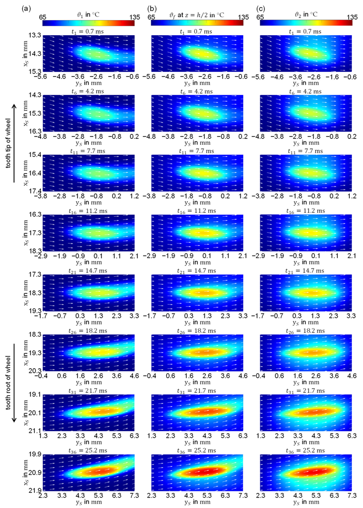
Figure 7 shows the contour plots of the temperature of the worm tooth flank ϑ 1 , fluid ϑ f at z = h 2 , and wheel tooth flank ϑ 2 .
Figure 7 shows that there is an almost steady high contact temperature throughout the meshing cycle correlating with an almost constant S R R (see Figure 2d). It increases from the tooth tip flank area to the tooth root flank area due to more severe contact conditions in the tooth root flank area (higher v m and higher F N ; see Figure 2c,e,f). The temperature distribution on the worm and wheel tooth flank, ϑ 1 and ϑ 2 in Figure 7a and Figure 7c, is governed by the orientation of their velocity vectors (see Figure 2a,b). The fluid temperature ϑ f at z = h 2 in Figure 7b is governed by the orientation of v m . The worm tooth flank shows a lower temperature than the wheel tooth flank because the heat is more efficiently removed via convection from the worm tooth flank. This can be understood by observing the significantly higher magnitude of the velocity vectors on the worm tooth flank in Figure 2a,b. Additionally, by comparing the temperature tails in Figure 7a,c, it can be seen that the heat on the worm tooth flank is efficiently removed toward the outlet, while the heat on the wheel tooth flank is, much less efficiently, removed toward the wheel tooth tip and the wheel tooth root.
The film thickness results presented in Figure 6b show no occurrence of dimples. Dimples are typically found in EHL contacts operating under high sliding conditions, high entrainment speeds, and low oil temperatures with solids featuring significantly different thermal effusivity (e.g., steel-on-glass contact in optical tribometer). This causes unequal temperature distribution in gap height direction, which results in a strong temperature-viscosity wedge that is responsible for the occurrence of dimples [25]. In this study, the thermal effusivities of worm and wheel are not significantly different, and the chosen oil temperature is relatively high (see Table 1). Hence, the temperature distribution in the gap height direction is relatively uniform. This can be seen in Figure 7 (see also Figure 8b), by observing that the highest temperature occurs in the middle of the oil film. It can be concluded that for the considered worm gear EHL contacts, temperature-viscosity wedges are not strong enough to cause the occurrence of dimples.
The results from Figure 6 and Figure 7 are further evaluated in terms of minimum and maximum values in Figure 8, complemented with the results for the time steps not shown in previous figures. In Figure 8a, the minimum and central film thicknesses h m and h c and the maximum fluid pressure p f , m a x are shown over a meshing cycle. Similarly, Figure 8b shows the maximum temperature of the worm and wheel tooth flank ϑ 1 , m a x and ϑ 2 , m a x and the maximum fluid temperature ϑ f ,   m a x at z = h 2 .
Figure 8a clearly shows that both h c and h m decrease towards the wheel tooth root, as the contact becomes slenderer (see k in Figure 4b). As shown in Figure 6, as k decreases, less oil is entrained in the contact, and more oil leaves the contact through the sides, which in turn results in less oil being available to maintain the oil film in the contact. On the other hand, p f , m a x is highest in the vicinity of tooth tip and root flank, reaching relatively constant values in between. From Figure 8b, it can be seen that the wheel flank made of bronze is hotter than the worm flank made of steel, while the maximum temperature is reached in the middle of the oil film. As shown in Figure 7, this can be attributed to less efficient heat removal by convection from the wheel tooth flank.

3.3. Classification of Film Thickness Results

To classify the results presented in Section 3.2, h c and h m from the EHL analysis are compared against analytically calculated values from established analytical approaches. The considered analytical approaches are based on the
  • h m calculation in worm gear contacts according to DIN 3996 (performed by SNETRA) [29];
  • h c and h m formulae for point contacts with lubricant entrainment at some intermediate angle, by Chittenden et al. [27];
  • h c and h m formulae for slender EHL contacts, by Wolf et al. [30,31].
According to the DIN 3996 standard for worm gears, h m can be calculated by assuming a line contact of two rollers with the reduced radius of curvature determined by the tooth flank geometries in the transverse direction to the meshing position [8,10]. Depending on the orientation of the entrainment velocity vector, the contacting rollers rotate relative to each other. Under this assumption, only the entrainment velocity component in the transverse direction to the meshing position is considered.
The input conditions for the analytical formulae of Chittenden et al. [27] and Wolf et al. [30,31] are taken at the center of the equivalent contact ( x = 0 ,   y = 0 ). The oil properties for all three analytical approaches ( μ 0 and α p ) are fitted using the Barus viscosity model to the experimentally measured low-shear viscosity data of PG460 at high pressure and ϑ o i l = 65   , given in [20].
In Figure 9, the h c and h m obtained from this study and the considered analytical approaches are compared. For Chittenden et al. [27] and Wolf et al. [30,31], the trends of h m and h c over the meshing cycle are similarly compared to the results from this study. However, significantly higher values are predicted except by Wolf et al. [30,31] for h m , which shows good agreement. Differences might be caused by the neglected non-Newtonian and thermal effects in the derivation process of the analytical formulae. As can be seen from Figure 2d and Figure 8b, the slide-to-roll ratio is S R R 2 , and the maximum fluid temperature ϑ f , m a x is above 100 °C for the whole meshing cycle. In the case of the calculation according to the DIN 3996, a different trend over the meshing cycle was predicted compared to the results from this study. This can be due to the assumption of a line contact between a set of rollers in the transverse direction to the meshing position.

4. Conclusions

This study introduced a numerical procedure for investigating the transient thermal EHL contact of worm gears with nonconjugate meshing action. Based on the presented results, the following conclusions can be drawn:
  • Worm gears with nonconjugate meshing action are characterized by a slender-like elliptical contact with small ellipticity ratio.
  • As the contact becomes slenderer toward the tooth root of the wheel, the quantity of the oil entrained in the contact decreases, and the side flow increases, which in turn results in a lower film thickness. In other words, as the worm gear contact becomes slenderer, the effect of entrainment speed on EHL film thickness diminishes.
  • The positive effect of the increasing entrainment speed toward the tooth root of the wheel on EHL film thickness could be restored by making the contact less slender. This could be achieved by increasing conformity between the flanks in the transverse direction to the meshing position.
  • The worm tooth flank is cooler than the wheel tooth flank, which is a consequence of more efficient heat removal via convection by the worm.
  • In terms of analytical approaches, the film thickness is overestimated, except for the minimum film thickness by Wolf et al. [30,31]. Calculation by DIN 3996 predicts a different trend of the minimum film thickness over the meshing cycle compared to the results from this study. This shows the difficulty in applying simple analytical formulae to capture the complex contact conditions of worm gears.
The presented results show that numerical modeling supports the understanding of mechanisms and is necessary to predict tribological details of slender-like EHL contacts in worm gears. Recent developments in using machine learning algorithms for film thickness predictions in EHL contacts [32] could be a promising way to transfer findings from complex numerical models to accurate and fast approaches. Because solid contacts are unavoidable in worm gear contacts, the adaption of the developed numerical model for modeling mixed lubrication and wear will be the focus of further investigations.

Author Contributions

Conceptualization, M.T., T.L., K.S. and R.L.; methodology, M.T., T.L., K.S. and R.L.; software, M.T.; validation, M.T.; formal analysis, M.T.; investigation, M.T.; resources, K.S., T.L. and M.T.; data curation, M.T.; writing—original draft preparation, M.T. and T.L.; writing—review and editing, M.T., T.L., K.S. and R.L.; visualization, M.T.; supervision, K.S., T.L. and R.L.; project administration, K.S. and T.L.; funding acquisition, K.S., T.L. and M.T. All authors have read and agreed to the published version of the manuscript.

Funding

This work was financially supported by the German Academic Exchange Service (DAAD).

Data Availability Statement

Not applicable.

Acknowledgments

The authors gratefully acknowledge Scott Bair for kindly providing PG460 parameters for an improved Yasutomi correlation.

Conflicts of Interest

The authors declare no conflict of interest. The funders had no role in the design of the study; in the collection, analyses, or interpretation of data; in the writing of the manuscript, or in the decision to publish the results.

Nomenclature

Latin symbols
A 1 Oil parameter for improved Yasutomi temperature–pressure–viscosity correlation
A 2 Oil parameter for improved Yasutomi temperature–pressure–viscosity correlation GPa 1
A c 1 , , 5 Coefficients of the oil heat capacity model
a Center distance of the considered worm gear pair
a x Semi-major Hertzian contact length m
a y Semi-minor Hertzian contact length m
b 1 Oil parameter for improved Yasutomi temperature–pressure–viscosity correlation GPa 1
b 2 Oil parameter for improved Yasutomi temperature–pressure–viscosity correlation
C Compliance matrix Pa
c p Specific heat capacity J / ( kg   K )
C 1 Oil parameter for improved Yasutomi temperature–pressure–viscosity correlation
C 2 Oil parameter for improved Yasutomi temperature–pressure–viscosity correlation
d i Reference diameter m
d λ 1 ,   d λ 2 Coefficients of the oil thermal conductivity model
D 1 Oil parameter for Dowson–Higginson density model GPa 1
D 2 Oil parameter for Dowson–Higginson density model GPa 1
e Thermal effusivity J / ( K s m 2 )
E Modulus of Elasticity Pa
E e q Equivalent Modulus of Elasticity Pa
f t Number of interpolated meshing positions between two meshing positions
F N Normal force N
F Dimensionless relative thermal expansivity of the free volume
g Undeformed gap between rigid ellipsoid and elastic body m
G i Carreau model parameter Pa
h Film thickness m
h c Central film thickness m
h m Minimum film thickness m
h f d , Flank distance in the direction parallel to the meshing position ( x -direction) m
H Dimensionless film thickness
h 0 Constant parameter of the film thickness equation
i Gear ratio
k Ellipticity ratio
n i Rotational speed min 1
n C , i Carreau model parameter
n E Number of the considered meshing positions
N x | y Mesh resolution in x - and y -direction of the contact mechanics numerical model
p f Hydrodynamic pressure Pa
P Dimensionless hydrodynamic pressure
p H Hertzian pressure Pa
p H , m a x Maximum Hertzian pressure Pa
R red , x ,   R red , y Reduced radii of curvatures in x - and y -directionm
R red , x 0 ,   R red , y 0 Reduced radii of curvatures in x - and y -direction at the contact center ( x = 0 , y = 0 ) m
R r e d , Reduced radius of curvature in the transverse direction to the meshing position(-direction) m
S R R Slide-to-roll ratio
T i Torque Nm
T Temperature K
T 0 Oil temperature K
T g Glass transition temperature
T g 0 Reference glass transition temperature
T ¯ Dimensionless temperature
t Time s
t ¯ Dimensionless time
t E Meshing time of a single tooth of the worm gears
U Displacement vector m
v f , x Fluid velocity in x -directionm/s
v f , y Fluid velocity in y -directionm/s
v i Velocity vector
Sliding speed in x -directionm/s
v g , y Sliding speed in y -direction m / s
v m Entrainment speedm/s
v m , 0 Entrainment speed evaluated at the contact center ( x = 0 , y = 0 ) m / s
v 1 , x Worm velocity component in x -direction m / s
v 1 , y Worm velocity component in x -directionm/s
v 2 , x Wheel velocity component in x -direction m / s
v 2 , y Wheel velocity component in y -direction m / s
x S ,   y S ,   z S Coordinates of SNETRA m
x ,   y ,   z Coordinates of the numerical EHL model m
X ,   Y ,   Z Dimensionless coordinates of the numerical EHL model
z i Number of teeth
Greek symbols
α p Pressure-viscosity coefficientPa−1
δ Elastic deflection of an equivalent body
δ ¯ Dimensionless elastic deflection of an equivalent body
t Time step sizes
ε Oil thermal expansivity K 1
ε 0 Oil thermal expansivity at ϑ o i l and atmospheric pressure K 1
ϵ Contact ratio
ϑ f Fluid temperature
ϑ f , m a x Maximum fluid temperature
ϑ o i l Reference oil temperature
ϑ 1 Temperature of worm flank surface
ϑ 2 Temperature of wheel flank surface
η Dynamic viscosity Pa   s
η ¯ Dimensionless dynamic viscosity
η 0 Oil dynamic viscosity at ϑ o i l and atmospheric pressure Pa   s
λ Thermal conductivity W / ( m   K )
λ 0 Oil thermal conductivity at ϑ o i l and atmospheric pressure W / ( m   K )
λ ρ Coefficient in the thermal expansivity model GPa 1
μ g Parameter for improved Yasutomi temperature–pressure–viscosity correlation Pa   s
ν Poisson’s ratio
ν e q Equivalent Poisson’s ratio
ν 40 Kinematic viscosity at ϑ o i l = 40   mm 2 / s
ν 100 Kinematic viscosity at ϑ o i l = 100   mm 2 / s
ρ Density kg / m 3
ρ ¯ Dimensionless density
ρ 0 Oil density at ϑ o i l and atmospheric pressure kg / m 3
ρ 15 Oil density at ϑ o i l = 15   and atmospheric pressure kg / m 3
F N Sum of the normal force over the meshing position N
τ Shear stress Pa
τ ¯ Dimensionless shear stress
τ ¯ z , x 0 ,   τ ¯ z , y 0 Shear stress components in the x - and y -direction over the computational domain
Indices
1 Worm
2 Wheel
f Fluid

References

  1. Niemann, G.; Winter, H. Maschinenelemente Band 3: Schraubrad-, Kegelrad-, Schnecken-, Ketten-, Riemen-, Reibradgetriebe, Kupplungen, Bremsen, Freiläufe [Machine Elements Volume 3: Helical, Bevel, Worm, Chain, Belt, Friction Gears, Clutches, Brakes, Freewheels]; 2., völlig neu bearbeitete Auflage; Springer: Berlin/Heidelberg, Germany, 2004; ISBN 978-3-642-62101-7. [Google Scholar]
  2. Kong, S.; Sharif, K.J.; Evans, H.P.; Snidle, R.W. Elastohydrodynamics of a Worm Gear Contact. ASME J. Tribol. 2001, 123, 268–275. [Google Scholar] [CrossRef] [Green Version]
  3. Simon, V. EHD Lubrication Characteristics of a New Type of Ground Cylindrical Worm Gearing. ASME J. Mech. Des. 1997, 119, 101–107. [Google Scholar] [CrossRef]
  4. Yang, F.; Su, D.; Gentle, C.R. Finite element modelling and load share analysis for involute worm gears with localized tooth contact. Proc. Inst. Mech. Eng. C J. Mech. Eng. Sci. 2001, 215, 805–816. [Google Scholar] [CrossRef]
  5. Sharif, K.J.; Kong, S.; Evans, H.P.; Snidle, R.W. Contact and elastohydrodynamic analysis of worm gears Part 1: Theoretical formulation. Proc. Inst. Mech. Eng. C J. Mech. Eng. Sci. 2001, 215, 817–830. [Google Scholar] [CrossRef] [Green Version]
  6. Sharif, K.J.; Kong, S.; Evans, H.P.; Snidle, R.W. Contact and elastohydrodynamic analysis of worm gears Part 2: Results. Proc. Inst. Mech. Eng. C J. Mech. Eng. Sci. 2001, 215, 831–846. [Google Scholar] [CrossRef] [Green Version]
  7. Sharif, K.J.; Evans, H.P.; Snidle, R.W.; Barnett, D.; Egorov, I.M. Effect of elastohydrodynamic film thickness on a wear model for worm gears. Proc. Inst. Mech. Eng. J J. Eng. Tribol. 2006, 220, 295–306. [Google Scholar] [CrossRef] [Green Version]
  8. Magyar, B. Tribo-dynamische Untersuchungen von Zylinderschneckengetrieben [Tribo-Dynamic Studies of Cylindrical Worm Gears]. Ph.D. Thesis, University of Kaiserslautern, Kaiserslautern, Germany, 2012. [Google Scholar]
  9. Venner, C.H. Multilevel Solution of the EHL Line and Point Contact Problems. Ph.D. Thesis, University of Twente, Enschede, The Netherlands, 1991. [Google Scholar]
  10. Oehler, M. Methodische Ansätze zur Optimierung des Wirkungsgrades von Schneckengetrieben [Methodical Approaches to Optimizing the Efficiency of Worm Gears]. Ph.D. Thesis, University of Kaiserslautern, Kaiserslautern, Germany, 2018. [Google Scholar]
  11. Habchi, W.; Bair, S. The role of the thermal conductivity of steel in quantitative elastohydrodynamic friction. Tribol. Int. 2019, 142, 105970. [Google Scholar] [CrossRef]
  12. Roth, P.; Sigmund, W.; Born, S.; Kadach, D.; Stahl, K. A Numerical Approach to the Calculation of the Surface Temperature Distribution of Worm Gears. In Proceedings of the ASME 2017 International Design Engineering Technical Conferences and Computers and Information in Engineering Conference, Cleveland, OH, USA, 6–9 August 2017. [Google Scholar] [CrossRef]
  13. Roth, P.; Hein, M.; Stahl, K. Scuffing load capacity calculation of worm gears. Forsch. Ing. 2022, 86, 503–511. [Google Scholar] [CrossRef]
  14. Daubach, K.; Oehler, M.; Sauer, B. Wear simulation of worm gears based on an energetic approach. Forsch. Ing. 2022, 86, 367–377. [Google Scholar] [CrossRef]
  15. Mohammadpour, M.; Theodossiades, S.; Rahnejat, H. Transient mixed non-Newtonian thermo-elastohydrodynamics of vehicle differential hypoid gears with starved partial counter-flow inlet boundary. Proc. Inst. Mech. Eng. J J. Eng. Tribol. 2014, 228, 1159–1173. [Google Scholar] [CrossRef] [Green Version]
  16. Almqvist, A.; Pérez-Ràfols, F. Scientific Computing with Applications in Tribology: A Course Compendium. 2019. Available online: http://urn.kb.se/resolve?urn=urn:nbn:se:ltu:diva-72934 (accessed on 25 October 2022).
  17. Habchi, W. Finite Element Modeling of Elastohydrodynamic Lubrication Problems; John Wiley & Sons Incorporated: Newark, NJ, USA, 2018. [Google Scholar]
  18. Farrenkopf, F.; Schwarz, A.; Lohner, T.; Stahl, K. Analysis of a Low-Loss Gear Geometry Using a Thermal Elastohydrodynamic Simulation including Mixed Lubrication. Lubricants 2022, 10, 200. [Google Scholar] [CrossRef]
  19. Bair, S.; Mary, C.; Bouscharain, N.; Vergne, P. An improved Yasutomi correlation for viscosity at high pressure. Proc. Inst. Mech. Eng. J J. Eng. Tribol. 2013, 227, 1056–1060. [Google Scholar] [CrossRef]
  20. Bair, S. High Pressure Rheology for Quantitative Elastohydrodynamics, 2nd ed.; Elsevier: Cambridge, MA, USA, 2019. [Google Scholar]
  21. Dowson, D.; Higginson, G.R. Elasto-Hydrodynamic Lubrication: The Fundamentals of Roller and Gear Lubrication, 1st ed.; Pergamon Press: Oxford, UK, 1966. [Google Scholar]
  22. Bos, J. Frictional Heating of Tribological Contacts. Ph.D. Thesis, University of Twente, Enschede, The Netherlands, 1994. [Google Scholar]
  23. Larsson, E.; Andersson, O. Lubricant thermal conductivity and heat capacity under high pressure. Proc. Inst. Mech. Eng. J J. Eng. Tribol. 2000, 214, 337–342. [Google Scholar] [CrossRef]
  24. Ziegltrum, A.; Lohner, T.; Stahl, K. TEHL Simulation on the Influence of Lubricants on the Frictional Losses of DLC Coated Gears. Lubricants 2018, 6, 17. [Google Scholar] [CrossRef] [Green Version]
  25. Tošić, M.; Larsson, R.; Lohner, T. Thermal Effects in Slender EHL Contacts. Lubricants 2022, 10, 89. [Google Scholar] [CrossRef]
  26. Chittenden, R.J.; Dowson, D.; Dunn, J.F.; Taylor, C.M. A Theoretical Analysis of the Isothermal Elastohydrodynamic Lubrication of Concentrated Contacts. I. Direction of Lubricant Entrainment Coincident with the Major Axis of the Hertzian Contact Ellipse. Proc. R. Soc. Lond. 1985, 397, 245–269. [Google Scholar] [CrossRef]
  27. Chittenden, R.J.; Dowson, D.; Dunn, J.F.; Taylor, C.M. A Theoretical Analysis of the Isothermal Elastohydrodynamic Lubrication of Concentrated Contacts. II. General Case, with Lubricant Entrainment along Either Principal Axis of the Hertzian Contact Ellipse or at Some Intermediate Angle. Proc. R. Soc. Lond. 1985, 397, 271–294. [Google Scholar]
  28. Wheeler, J.D.; Fillot, N.; Vergne, P.; Philippon, D.; Morales-Espejel, G. On the crucial role of ellipticity on elastohydrodynamic film thickness and friction. Proc. Inst. Mech. Eng. J J. Eng. Tribol. 2016, 230, 1503–1515. [Google Scholar] [CrossRef]
  29. DIN 3996:2019; Calculation of load capacity of cylindrical worm gear pairs with rectangular crossing axis(in German). German Institute for Standardization: Berlin, Germany, 2019.
  30. Wolf, M.; Solovyev, S.; Fatemi, A. Film thickness in elastohydrodynamically lubricated slender elliptic contacts: Part I—Numerical studies of central film thickness. Proc. Inst. Mech. Eng. J J. Eng. Tribol. 2022, 236, 1043–1055. [Google Scholar] [CrossRef]
  31. Wolf, M.; Sperka, P.; Fryza, J.; Fatemi, A. Film Thickness in Elastohydrodynamically Lubricated Slender Elliptic Contacts: Part II—Experimental Validation and Minimum Film Thickness. Proc. Inst. Mech. Eng. J J. Eng. Tribol. 2022, 236, 2477–2490. [Google Scholar] [CrossRef]
  32. Marian, M.; Mursak, J.; Bartz, M.; Profito, F.; Rosenkrantz, A.; Wartzack, S. Predicting EHL film thickness parameters by machine learning approaches. Friction 2022. [Google Scholar] [CrossRef]
Figure 1. (a) Considered worm gear; (b) zoomed section of the wheel showing selected meshing positions; (c) schematic area of gear contact on the wheel.
Machines 11 00089 g001
Figure 2. Contact conditions across the area of gear contact obtained from SNETRA (the number of meshing positions was reduced for illustration purposes). (a) Velocity vectors of the worm v 1 ( x S ,   y S , t ) ; (b) velocity vectors of the wheel v 2 ( x S ,   y S , t ) ; (c) entrainment velocity v m ( x S ,   y S , t ) ; (d) slide-to-roll ratio S R R ( x S ,   y S , t ) ; (e) normal force F N ( x S ,   y S , t ) ; (f) sum of normal force F N ( t ) ; (g) flank distance in the direction parallel to the meshing position h f d , ( x S ,   y S , t ) ; (h) reduced radius of curvature in the transverse direction to the meshing position R r e d , ( x S ,   y S , t ) .
Machines 11 00089 g002
Figure 3. Numerical EHL model. (a) Dimensionless computational domains; (b) top view of meshed fluid domain Ω P .
Machines 11 00089 g003
Figure 4. (a) Dry contact area over a meshing cycle (the number of meshing positions was reduced for illustration purposes). (b) Ellipticity ratio k and reduced radii of curvatures R r e d , x 0 and R r e d , y 0 .
Machines 11 00089 g004
Figure 5. Three-dimensional surface plots at t 1 = 0.7   ms and t 36 = 25.2   ms . (a) Fluid pressure p f ; (b) film thickness h ; (c) fluid temperature ϑ f at z = h 2 .
Machines 11 00089 g005
Figure 6. Contour plots with entrainment velocity vector v m for eight meshing positions ( t i = { 0.7 ,   4.2 ,   7.7 ,   11.2 ,   14.7 ,   18.2 ,   21.7 ,   25.2 }   ms ) of a meshing cycle. (a) Fluid pressure p f ; (b) film thickness h ; (c) fluid velocity v f at z = h 2 .
Machines 11 00089 g006
Figure 7. Contour plots with entrainment velocity vector v m for eight meshing positions ( t i = { 0.7 ,   4.2 ,   7.7 ,   11.2 ,   14.7 ,   18.2 ,   21.7 ,   25.2 }   ms ) of a meshing cycle. (a) Temperature of the worm tooth flank ϑ 1 ; (b) fluid temperature ϑ f at z = h 2 ; (c) temperature of the wheel tooth flank ϑ 2 .
Machines 11 00089 g007
Figure 8. Minimum and maximum values over a meshing cycle. (a) Minimum and central film thicknesses h m and h c and maximum fluid pressure p f , m a x ; (b) maximum temperature on worm and wheel tooth flank ϑ 1 , m a x and ϑ 2 , m a x and maximum fluid temperature ϑ f , m a x at z = h 2 .
Machines 11 00089 g008
Figure 9. Comparison of h c (a) and h m (b) derived from this study and analytical approaches over a meshing cycle.
Machines 11 00089 g009
Table 1. Considered worm gear geometry, operating conditions, material, and oil properties.
Worm (1)Wheel (2)
Worm gear geometry
Reference diameter d 1 | 2 36 164 mm
Number of teeth z 1 | 2 2 41
Center distance a 100 mm
Gear ratio i 20.5
Contact ratio ϵ 1.681
Operating conditions
n 1 | 2 2000 97.56 min 1
T 1 | 2 19.51 400 Nm
ϑ o i l 65
Solid material properties
MaterialSteel 16MnCr5 [10]Bronze CuSn12Ni2-C [10]
E 210 98.1 GPa
ν 0.3 0.35
c p 431 385 J / ( kgK )
λ 21 [11] 56 W / ( mK )
ρ 7760 8710 kg / m 3
e = λ ρ c p 8381 13 , 704 J / ( K s m 2 )
Oil properties of PG460 [10]
ν 40 460 mm 2 / s
ν 100 71 mm 2 / s
ρ 15 1073 kg / m 3
Table 2. Parameters for modeling the properties of the considered oil PG460.
Improved Yasutomi Correlation
μ g 1 × 10 12 Pa   s
T g 0 71.67
A 1 268.5
A 2 0.2558 GPa 1
b 1 7.36 GPa 1
b 2 0.3746
C 1 14.84
C 2 22.35
Multicomponent-modified Carreau viscosity model for mixtures [20]
n C , 1 0.63
n C , 2
G 1 2.7 × 10 5 Pa
G 2
Dowson-Higginson equation parameters [5]
D 1 0.67   GPa 1
D 2 2.68 GPa 1
ε 0 7.1 × 10 4 K 1
λ ρ 1.5 GPa 1
Disclaimer/Publisher’s Note: The statements, opinions and data contained in all publications are solely those of the individual author(s) and contributor(s) and not of MDPI and/or the editor(s). MDPI and/or the editor(s) disclaim responsibility for any injury to people or property resulting from any ideas, methods, instructions or products referred to in the content.