Article

Analysis of Elastohydrodynamic Lubrication (EHL) Characteristics of Port Plate Pair of a Piston Pump

School of Mechanical and Automotive Engineering, Shanghai University of Engineering Science, Shanghai 201620, China
*
Author to whom correspondence should be addressed.
Machines 2022, 10(12), 1109; https://doi.org/10.3390/machines10121109
Submission received: 5 October 2022 / Revised: 15 November 2022 / Accepted: 19 November 2022 / Published: 22 November 2022
(This article belongs to the Special Issue Elastohydrodynamic Lubrication)

Abstract

:
This article presents a steady-state elastohydrodynamic lubrication model for the contact and sliding interface of an axial piston pump’s port plate pair. The wedge-shaped oil film thickness, pressure, viscosity, and elastic deformation distribution of the port plate pair were investigated by using the finite difference method. The elastohydrodynamic lubrication characteristics for different operating parameters and two materials of the port plate pair were analyzed for comparison. Existing conditions for the EHL were calculated, and variations in leakage and friction coefficients were investigated. The results show that the elastic deformation of the interface greatly influences the oil film’s overall performance, which is related to the material, inlet pressure, velocity, viscosity, and the minimum oil film thickness that determines the EHL. The deformation caused by oil film pressure greatly influences the model leakage and friction coefficient, especially when the deformation is equal to the oil film clearance.

1. Introduction

Due to its high flexibility, the hydraulic system has been widely used in many industrial and aerospace applications. The axial piston pump is the critical component of many hydraulic systems. Because of its compact structure and convenient flow adjustment, it is widely used in various working conditions [1,2]. One of the leading causes of degradation in the performance of axial piston pumps is the wear of the vital frictional pairs, so the design of the lubrication interface is key to the performance of a pump. In addition, the primary source of power loss of the axial piston pump is viscous dissipation and leakage of the lubrication interface, so the service life of the axial piston pump is affected by structural parameters [3,4,5,6,7,8]. Among the three lubricating interfaces, the cylinder block/valve plate interface has the maximum contact area, which determines the leakage and energy dissipation of the axial piston pump [9]. In addition, contact loads often affect the surface of the valve plate and cylinder block, producing sizeable local stress and leading to component failure [10,11]. Therefore, the cylinder block/valve plate interface is one of the most critical design elements in the axial piston pump [12]. In addition to the hydrodynamic effects, the oil film thickness is also affected by surface deformation due to high operating pressure, which is usually of the same magnitude as the oil film thickness [13,14]. Therefore, small surface deformations significantly affect the pressure distribution of the interface [15]. The strengthening effect of fluid-solid coupling makes the oil viscosity change sharply, the sealing lubrication performance decrease, the friction pair wears seriously, and the local elastic stress and deformation of the core rotating parts increase [16]. The formation of the EHL takes into account the viscous effect and the elastic deformation between two metal surfaces [17,18]. The EHL model dramatically improves the theoretical models’ simulation accuracy by considering the interface’s micro-surface deformation.
For more than half a century, scholars at home and abroad have carried out theoretical and experimental research on the axial piston pump. For the first time, Yamaguchi introduced a numerical calculation method to calculate the pressure field distribution of the oil film in the port plate pair of the axial piston pump [19,20,21]. Pan et al. used the finite difference method to calculate the oil film thickness between the cylinder block and the port plate [22]. Bergada studied the leakage problem between the axial piston pump’s cylinder block and valve plate [23]. Huang assumed that elastic deformation could occur in the cylinder block and used the finite element method to calculate the pressure elastic deformation. The real-time correction of the oil film thickness is realized based on considering the elastic deformation. The simulation data obtained are closer to reality but cannot be used to calculate the high-pressure condition [24]. According to the Reynolds equation, Wang deduced the formula for the oil film pressure of the port pair and numerically analyzed the distribution of the oil film pressure field and temperature field [25]. Lin and Hu solved the dynamic friction model of slipper bearing with a genetic algorithm. They discussed the influence of cylinder speed, loading pressure, and oil viscosity on oil film thickness [26]. Li et al. analyzed the hydrothermal structure coupling of the friction pair of the valve plate in the axial piston pump. They revealed the coupling mechanism of internal multi-physical fields [27]. In 2009, a multi-body dynamic model of complete fluid-structure–heat coupling for piston/cylinder pair was proposed by Pelosi [28]. In 2015, Schenk established a transient thermal elastohydrodynamic lubrication model for the slipper/swashplate of an axial piston engine, considering a non-isothermal fluid model, pressure, and thermal deformation [29,30]. Tang et al. proposed a new TEHD lubrication model for the axial piston pump’s slipper pair and discussed the slipper pair’s deformation, oil film thickness, and pressure distribution. The oil film thickness is consistent with the measured value [31]. Qian et al. propose a new direct measurement method to achieve a high-precision pneumatic cylinder friction test [32,33,34].
In summary, the abovementioned analytical studies reveal that the oil film thickness and pressure studies are relatively common and thorough. However, studies on fluid–solid coupling for surface contact model of port plate pair are relatively few, especially considering the influence law of each lubrication parameter under the EHL conditions and the variation law of minimum oil film thickness. Therefore, the numerical coupling model of the lubrication performance of the cylinder block and valve plate of the axial piston pump is established. The model considers the load adaptivity of the port plate pair and solves the oil film pressure using finite differential methods. The point contact elastohydrodynamic lubrication model is adopted, the solid deformation effect and viscous extrusion under pressure are considered, the different working conditions of the port plate pair are compared and analyzed, and the fluid structure coupling mechanism is revealed. The results reveal the variation of the oil film’s pressure, secondary stress, and deformation. Therefore, it can lay the foundation for the design and improvement of the port plate pair.

2. Establishment and Solution of the Port Plate Pair Mathematical Model

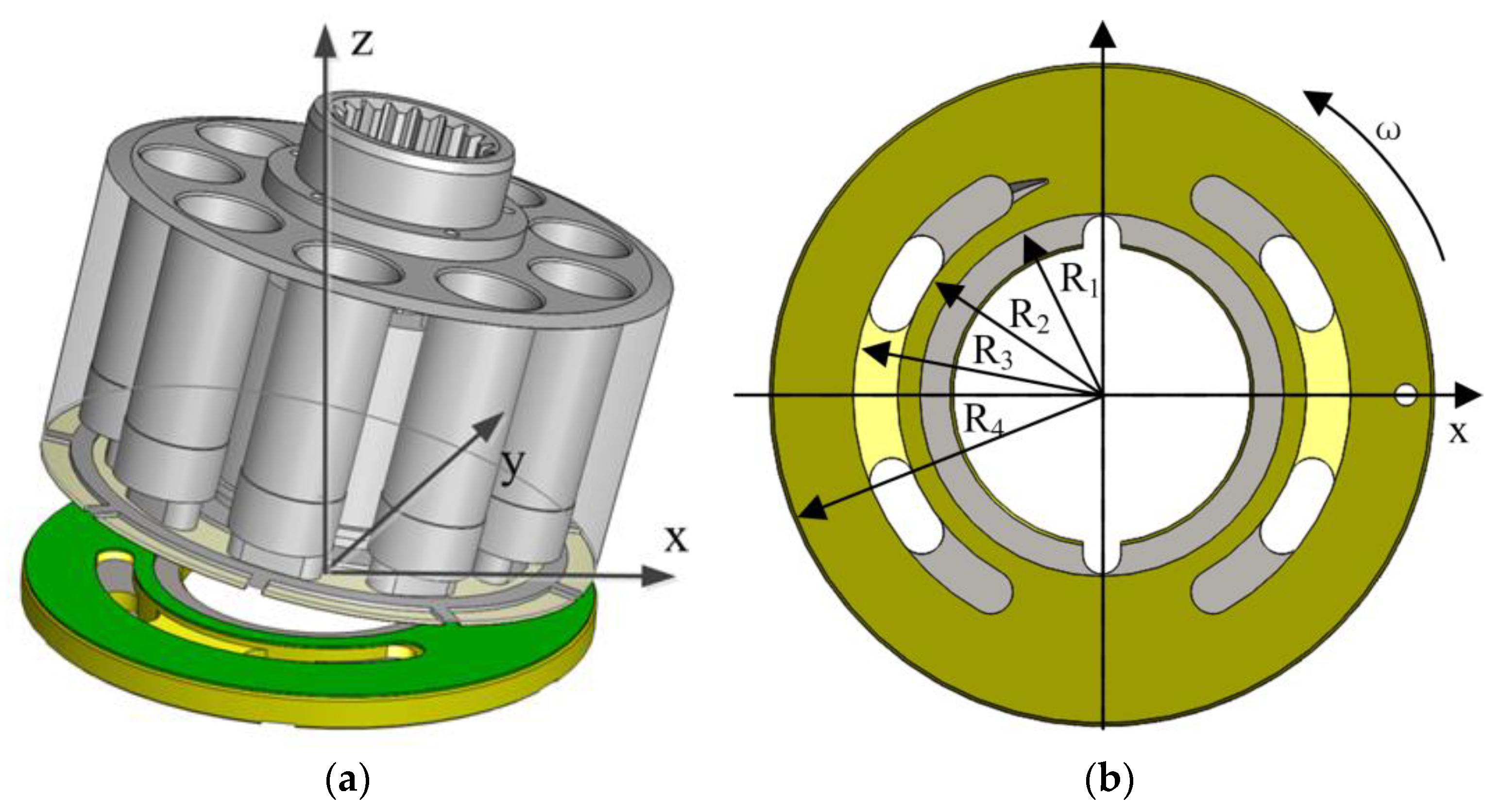
2.1. Model Calculation of the Port Plate Pair

Figure 1 shows the model of the port plate with an inclined cylinder block at the top of the valve plate: Figure 1a shows the assembly diagram of the valve plate and cylinder block; Figure 1b is a schematic diagram of the valve plate. The values of R1 to R4 are shown in Table 1. The cylinder block is tilted against the valve plate and rotated counterclockwise. The oil film in the contact area between the valve plate and the cylinder block is annular [35,36,37].
A low Reynolds number characterizes the fluid flow in the lubrication clearance. The governing equations of the lubrication model include the Reynolds equation, oil film thickness equation, deformation equation, and viscosity–pressure equation [38].
Reynolds equation:
r ( r h 3 η p r ) + 1 r θ ( h 3 η p θ ) = 6 ω r h θ
Oil film thickness equation:
h ( x , y ) = h c + v ( x , y ) h c = h O + R sin θ tan φ
Deformation equation:
v ( x , y ) = 2 π E Ω p ( s , t ) ( x s ) 2 + ( y t ) 2 d s d t 1 E = 1 2 ( 1 V 1 2 E 1 + 1 V 2 2 E 2 )
Under the EHL conditions, the elastic deformation of the valve plate and cylinder surface will change the shape of oil film clearance, and the deformation will be the surface settlement. Therefore, the elastic deformation equation is superimposed on the film thickness equation to calculate the EHL.
In addition to the elastic deformation of the contact surface in the EHL theory, the oil viscosity effect is also involved as a function of pressure according to the viscosity–pressure equation.
Viscosity–pressure equation:
η = η 0   e x p { ( ln η 0   + 9.67 ) [ 1 + ( 1 + p p 0 ) z ] } z = 0.68

2.2. Model Calculation of the EHL

The viscosity of the viscosity–pressure equation and the elastic deformation of the film thickness equation varies with the change in pressure. The initial pressure distribution for calculating the film thickness and viscosity is given. Then the new pressure distribution is solved by using the Reynolds equation, and the original pressure distribution is iteratively modified. The elastic deformation of the film is calculated, and the thickness of the film is changed. The iteration ends once the pressure difference between the two iterations is very close. The distribution of final pressure and film thickness with elastic deformation is obtained.
Figure 2 shows the EHL model: Figure 2a is an elastic deformation at any point of contact; Figure 2b is an elastic deformation of surface contact. The contact surface is discretized to solve the pressure distribution of each point. When solving elastic deformation, surface contact becomes point-to-point contact. We replace the elastic deformation of each point in the discrete state with the point contact model, and then extend to the whole surface contact in turn. This paper uses the deformation matrix method to solve the elastic deformation problem.
The deformation displacement:
δ x , y = 2 π E Ω p ( x , y ) x 2 + y 2 d x d y
Polar coordinates transformation:
x = r cos θ ,   y = r sin θ δ ( x , y ) = 2 π E Ω p ( r , θ ) d r d θ

2.3. Mesh Generation

A discrete form of elastic deformation Equation [39]:
δ k l = 2 π E i = 1 n j = 1 m D i j k l p i j
Compute all of D i j k l at once and store it. Then, calculate the deformation repeatedly during the iteration and substitute into Equation (6).
Isometric grid:
D i j k l = D k j i l D i j k l = D i l k j
The calculation formula of the elastic deformation:
δ i j = Δ x k = 1 N l = 1 N a i k , j l p k l
where:
a i k , j l = ( j l + 0.5 ) · l n [ f ( j l + 0.5 , i k + 0.5 ) f ( j l 0.5 , i k 0.5 ) ] + ( i k 0.5 ) · l n [ f ( i k 0.5 , j l 0.5 ) f ( i k + 0.5 , j l 0.5 ) ] + ( j l 0.5 ) · l n [ f ( j l 0.5 , i k 0.5 ) f ( j l + 0.5 , i k 0.5 ) ] + ( i k + 0.5 ) · l n [ f ( i k + 0.5 , j l + 0.5 ) f ( i k 0.5 , j l + 0.5 ) ]
where:
f ( x , y ) = x + x 2 + y 2

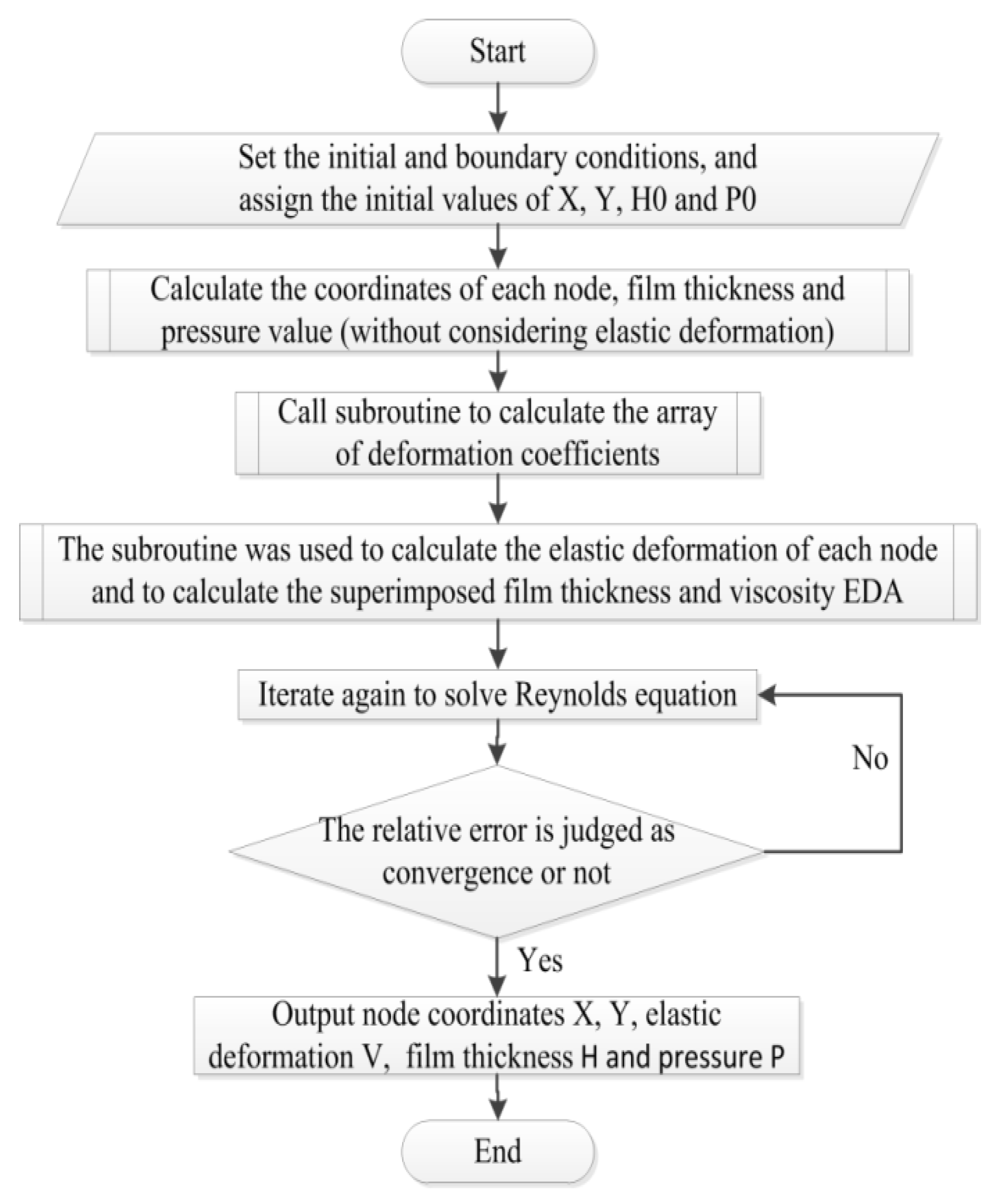
2.4. Program Block Diagram

The structure parameters of the port plate pair are determined. The lubrication interface of the port pair has meshed, and the boundary conditions are set. The finite difference method solves the Reynolds equation of oil film thickness and pressure. The over-relaxation iteration method is used to reduce computational complexity and time. The numerical calculation is carried out with the FORTRAN language. Figure 3 is the calculation block diagram of isothermal EHL.

3. Oil Film Clearance and Pressure Distribution under the EHL Characteristics

Table 1 shows the normal operating parameters of the port plate pair.

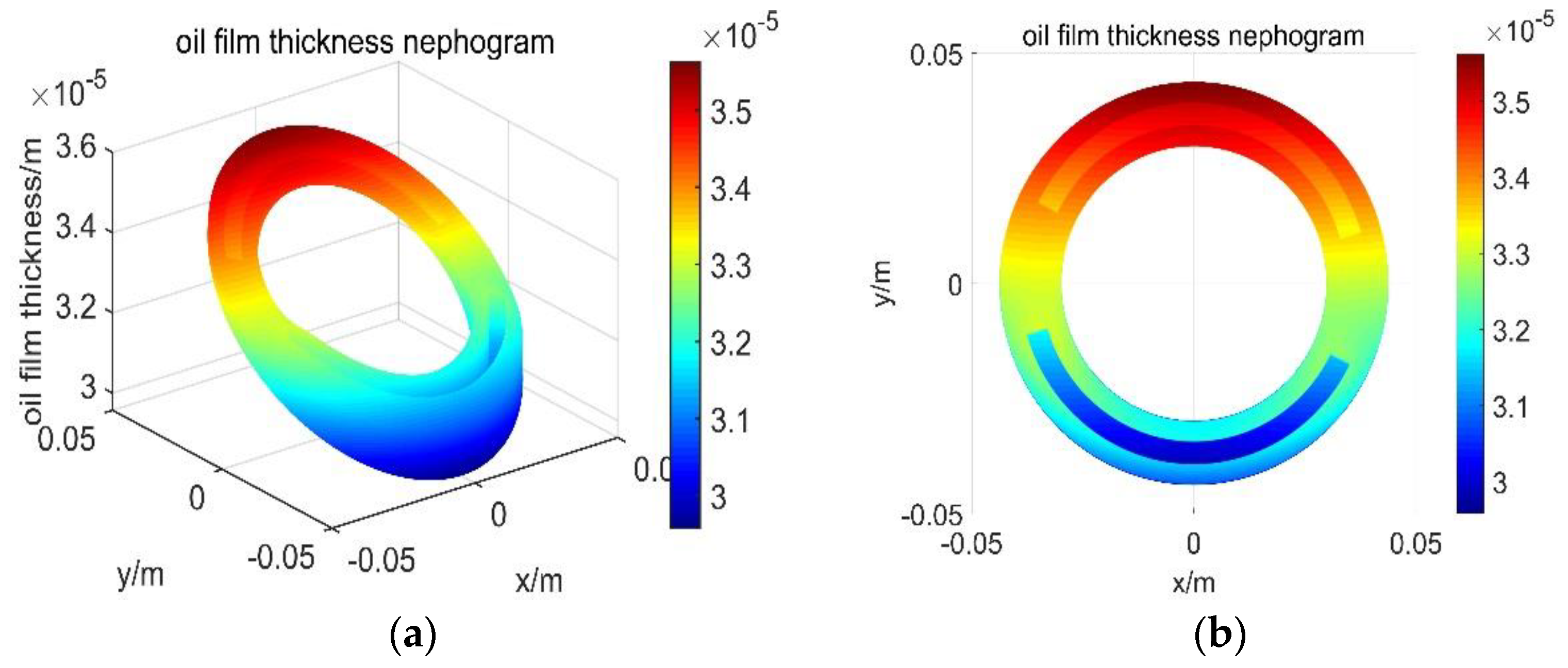
3.1. Distribution of the Oil Film Thickness

Figure 4 shows the distribution of oil film thickness: Due to the tilt of the cylinder, the oil film thickness distribution is not uniform, and its thickness varies with the circumferential angle. At 0°, the oil film is located on the inclined central axis, and the oil thickness is the initial oil film thickness h0 at this point. At 90°, the oil thickness reaches the maximum with the increase in angle. Then, the oil thickness begins to decrease as the circumferential angle increases. At 270° the side of the cylinder tilts, and the oil thickness reaches the minimum. Until the final 360°, the oil thickness increases again to the initial oil film thickness h0.

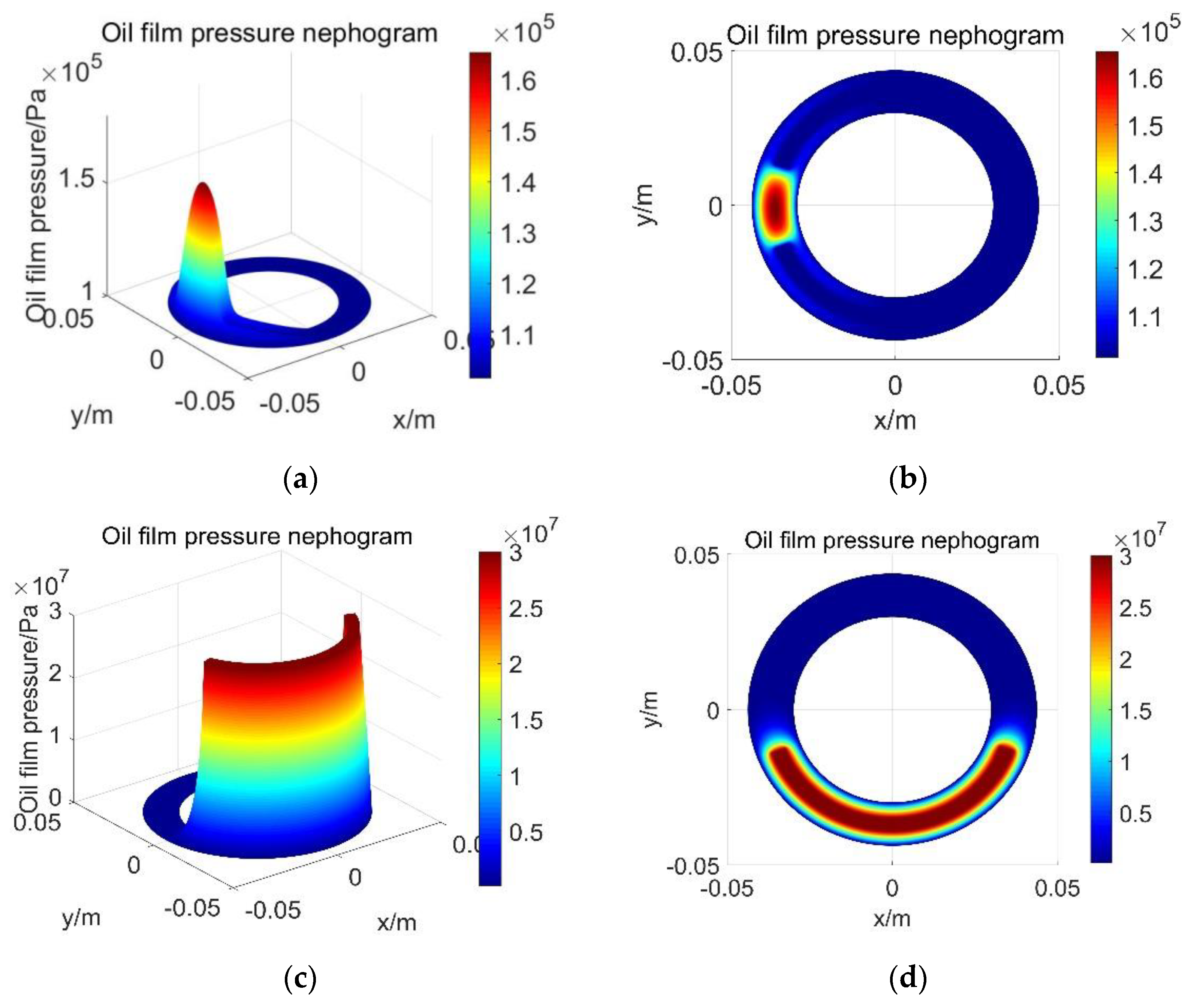
3.2. Oil Film Pressure Distribution

Figure 5 shows the distribution of oil film pressure. In the no-load condition, the oil film pressure is concentrated in the convergence area of the wedge-shaped oil film gap due to the hydrodynamic pressure effect, and the oil film pressure is in the form of a single peak, as shown in Figure 5a,b.
The wedge-shaped oil film of the port plate pair presents 35 MPa in working condition at the high-pressure oil port, and the hydrodynamic pressure effect appears in the convergence area of the wedge-shaped oil film at the counterclockwise boundary of the high-pressure oil port, as shown in Figure 5c,d.
As the high-pressure oil is passed into the high-pressure oil port at this time, resulting in excessive pressure at the high pressure oil port, the hydrodynamic pressure of the oil film is far less than the pushing force formed by the hydrostatic pressure. Therefore, the peak pressure generated by the hydrodynamic pressure effect is not easy to observe and compare.

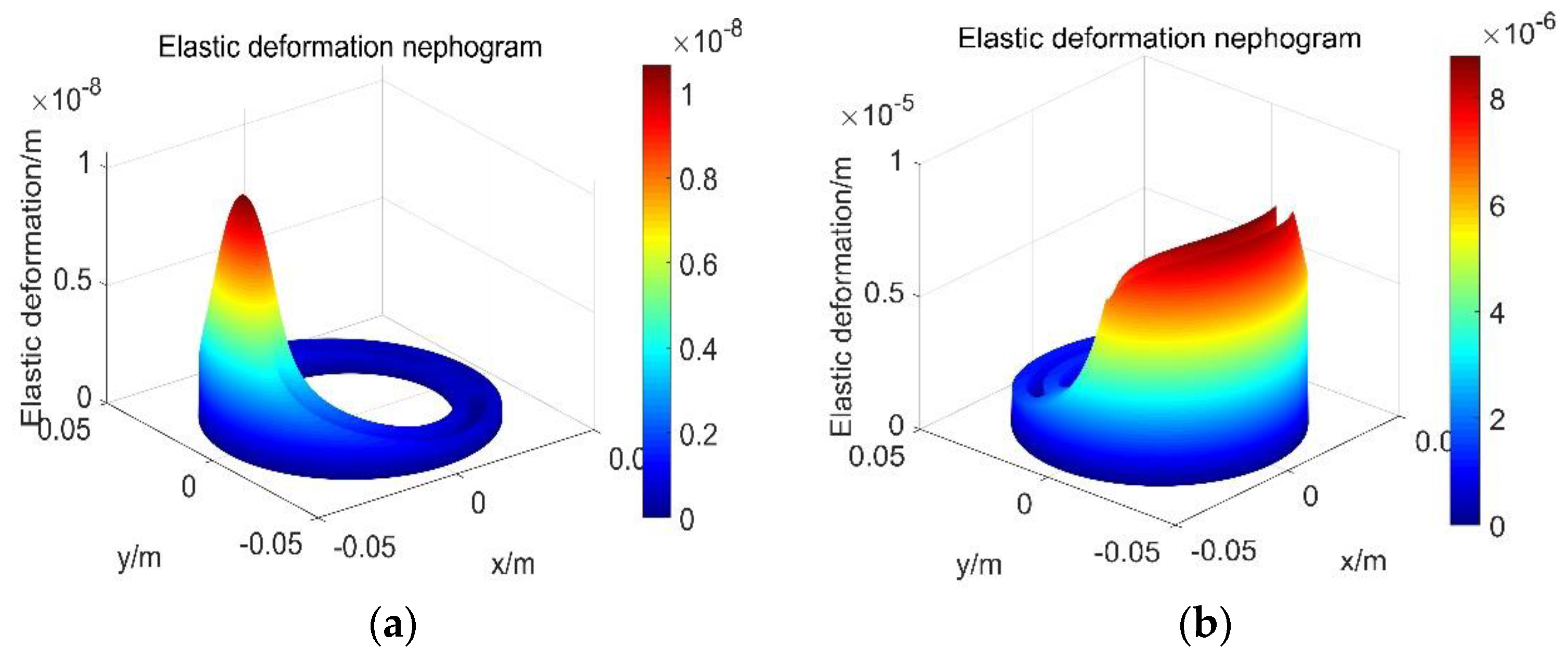
3.3. Elastic Deformation Distribution of Oil Film

Figure 6 shows the elastic deformation distribution of oil film. As the valve plate is a circular thick plate structure under the pressure of surface oil film, the surface of the valve plate will produce vertical deformation. Its deformation can be explained by the elastic deformation theory, which is related to the pressure on its surface and the material of the valve plate and cylinder, so the elastic deformation distribution of the valve plate will be similar to the oil film pressure distribution.
In no-load conditions, the elastic deformation is concentrated in the convergence area of wedge-shaped oil film, showing a single peak pattern. However, under the working pressure of 35 MPa, the elastic deformation is mainly concentrated in the sealing area around the high-pressure oil port.

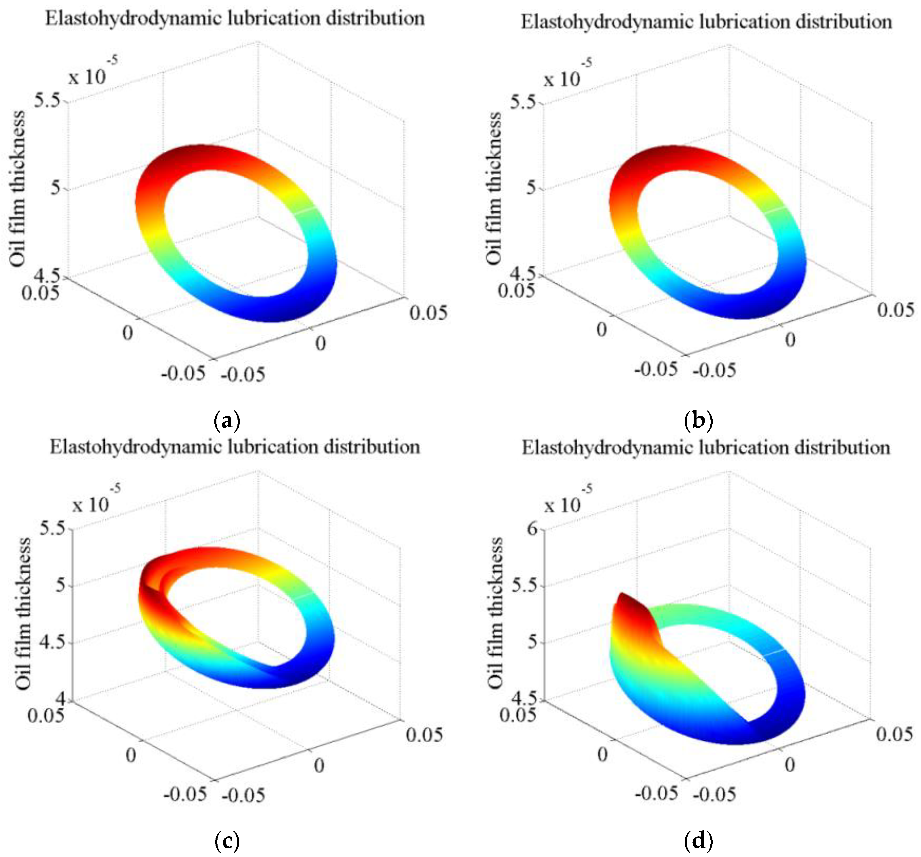
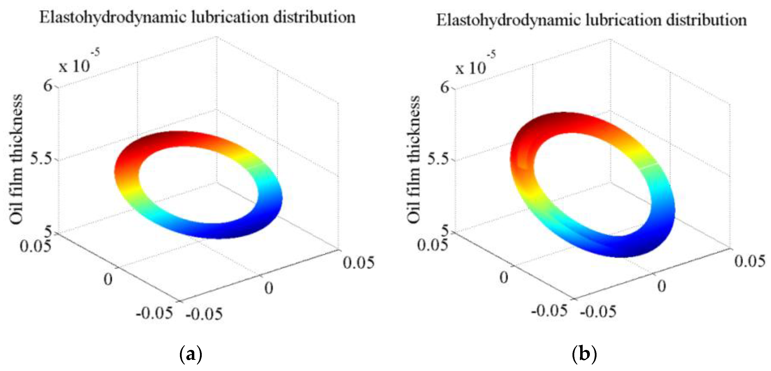
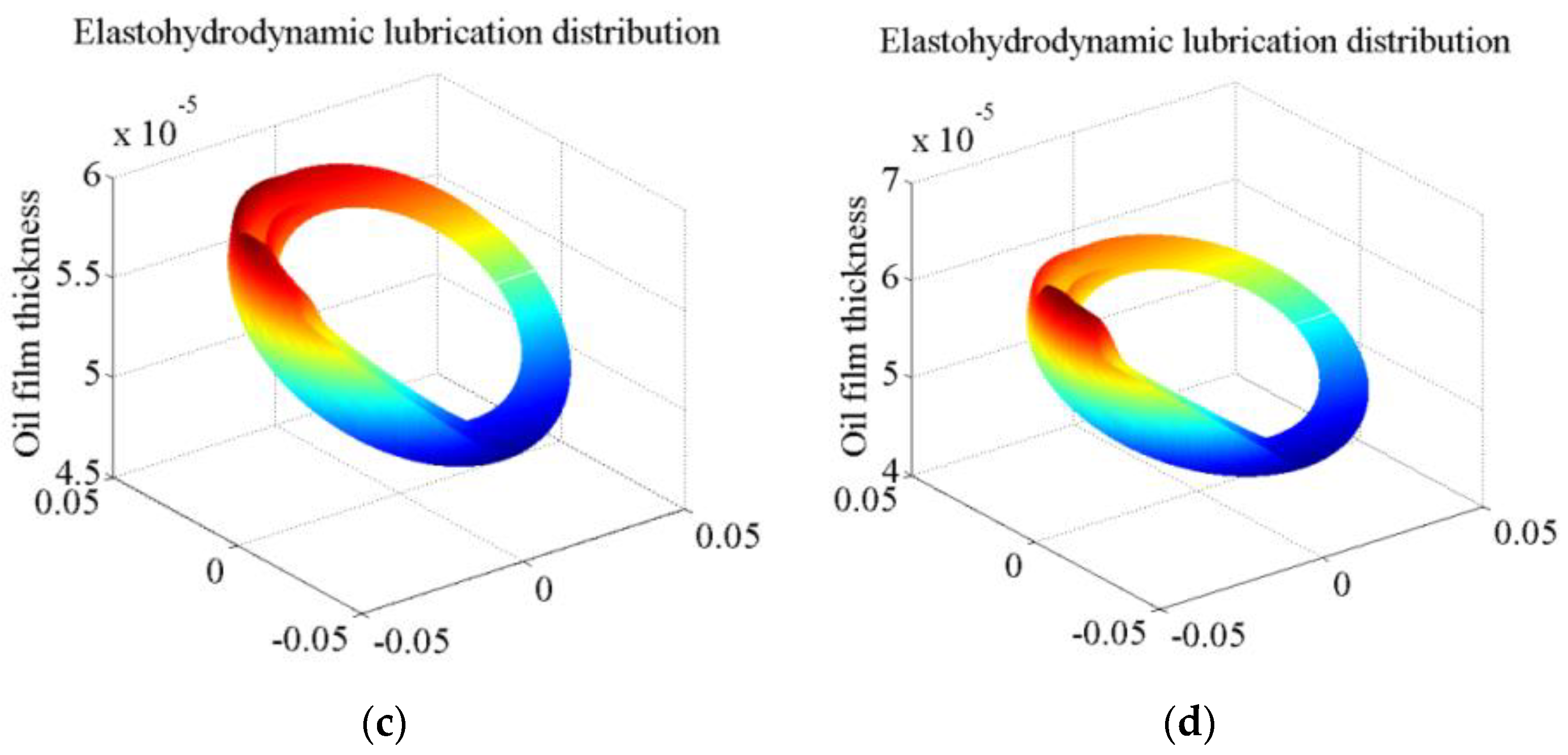
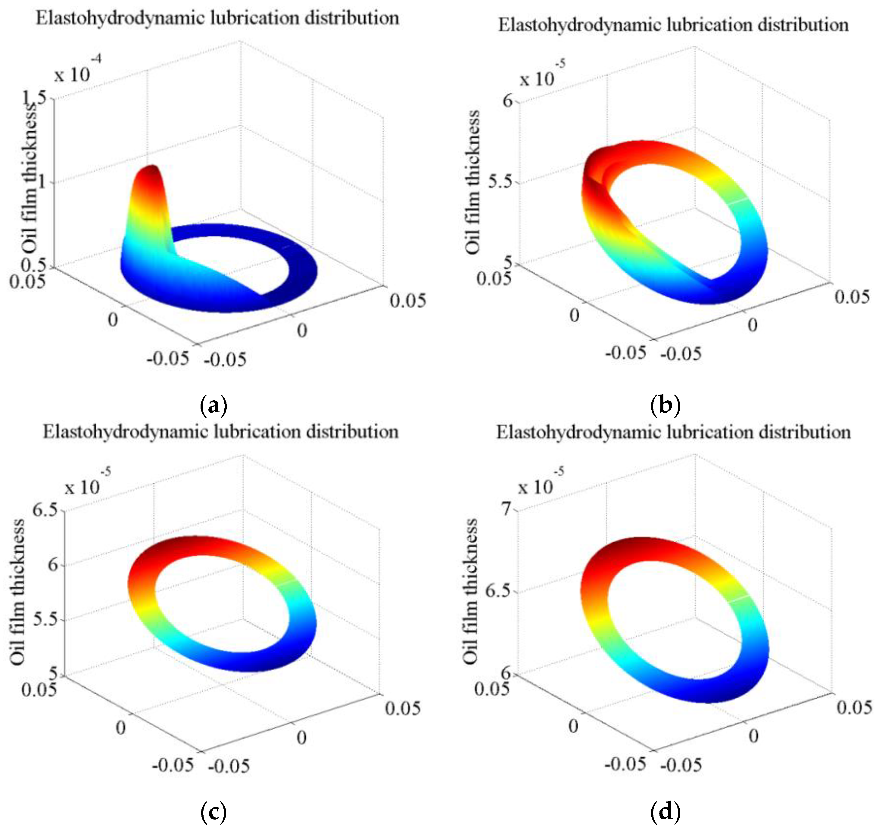
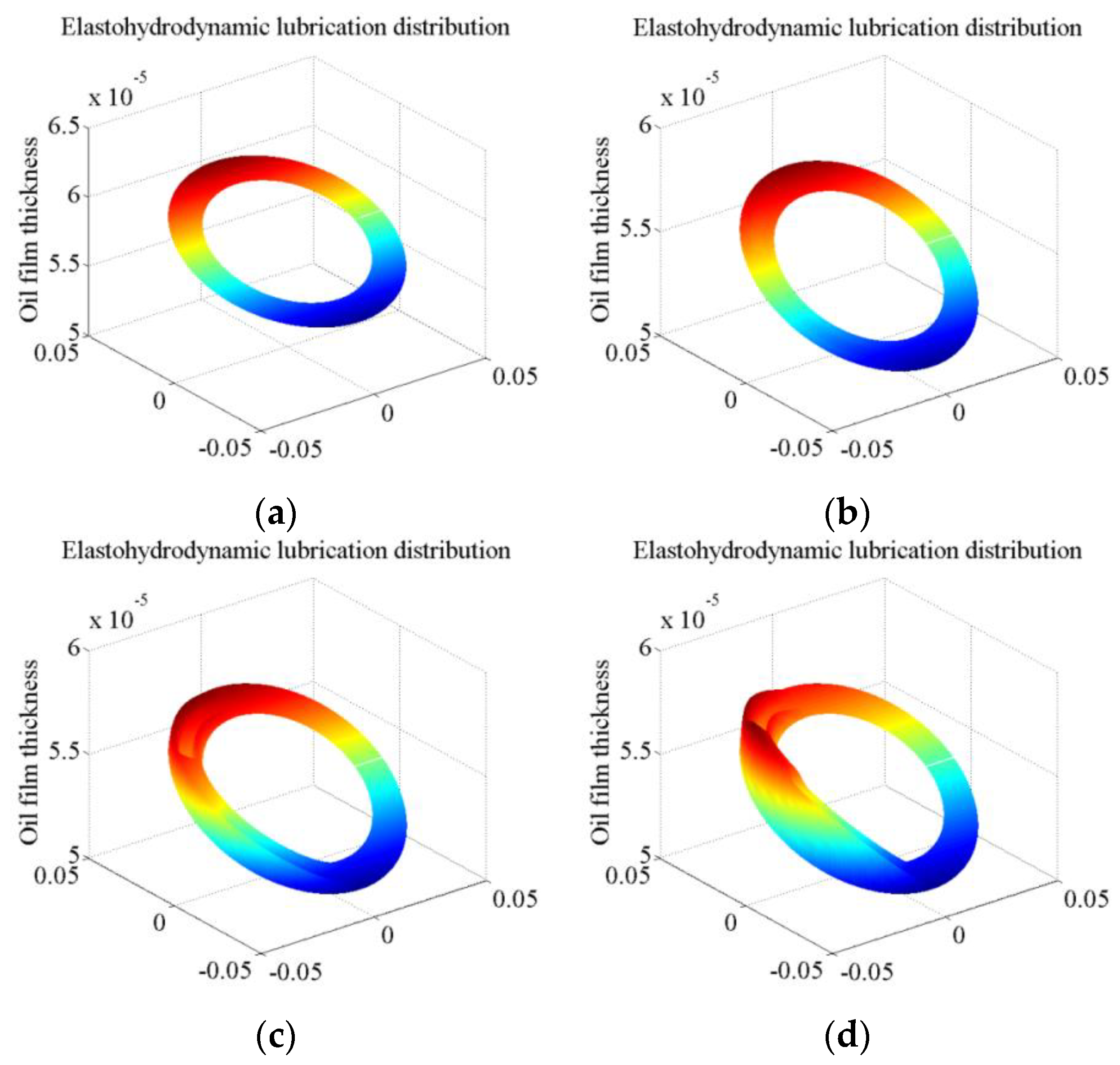
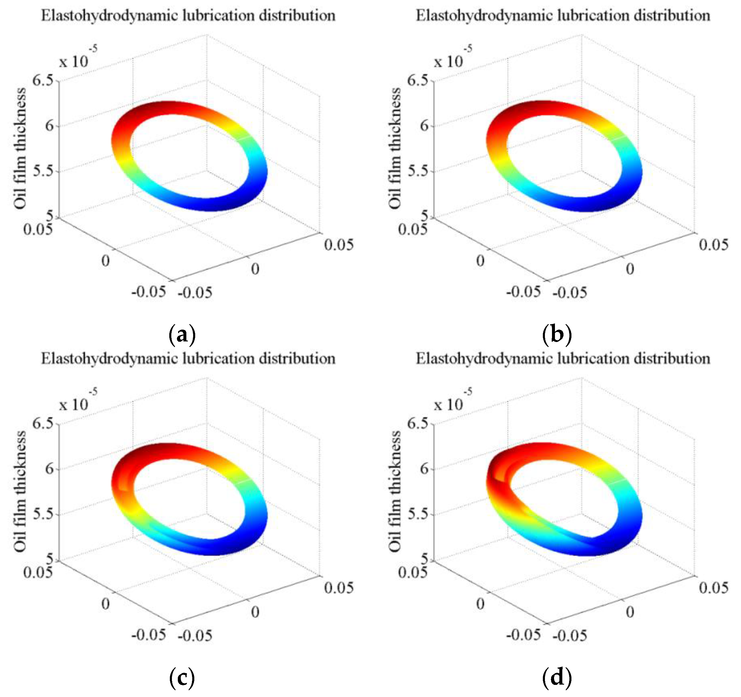
3.4. Oil Film EHL Distribution

Figure 7 shows the oil film clearance under elastic deformation: The oil film thickness distribution considering EHL can be obtained by accumulating the elastic deformation amount and the oil film thickness. Due to the tilting of the cylinder, the oil film pressure around the low-pressure oil port is small, the oil film thickness is thick, and the elastic deformation is inapparent compared with the oil film thickness without considering the EHL. In contrast, around the high-pressure oil port, the elastic deformation can be visually seen to increase significantly due to the higher oil film pressure.

3.5. Analysis of EHL Characteristics

Figure 4, Figure 5, Figure 6 and Figure 7 shows oil film thickness, elastic deformation, and pressure distribution. The following analysis can be obtained from the variation rules of the EHL characteristics presented in the figure.
(1)
Wedge oil film thickness varies with the inclination angle of the cylinder. It is thicker on the top and thinner on the bottom. Oil film pressure distribution in the sealing zone is nonlinear, resulting in dynamic changes in the oil film; oil film thickness in the low-pressure zone is thick. As the oil inlet and outlet of the valve plate are in a state of high pressure and low pressure, the cylinder block will be subjected to unloading torque, resulting in a slight inclination.
(2)
The elastic deformation is mainly concentrated in the anticlockwise transition of the high-pressure oil outlet. Therefore, the elastic deformation of the cylinder block/valve plate significantly influences the overall performance of fluid oil film.

4. Calculation of the EHL Characteristics of Two Pairs of Port Plate Pair

The high-pressure oil will leak through the sealing ring, forming static pressure support. The oil film and pressure distribution are formed by the combined action of static pressure, dynamic pressure, and elastic deformation. Table 2 shows the mechanical properties of the valve plate/cylinder block. Two port plate pairs with different materials are selected to study the EHL characteristics and make a comparison.

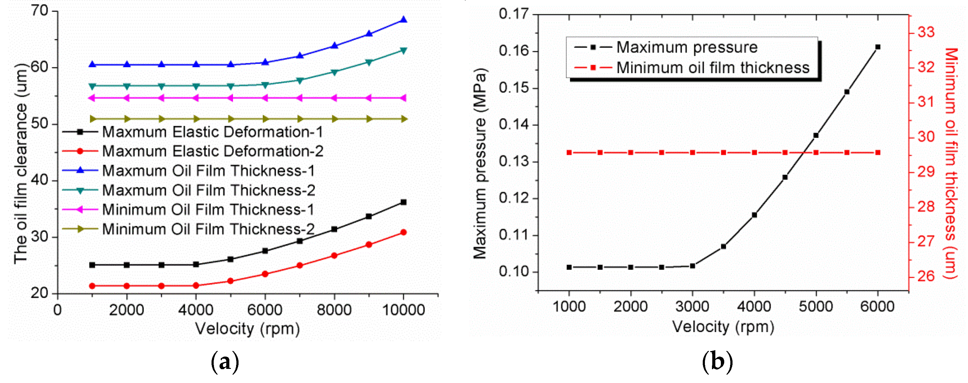
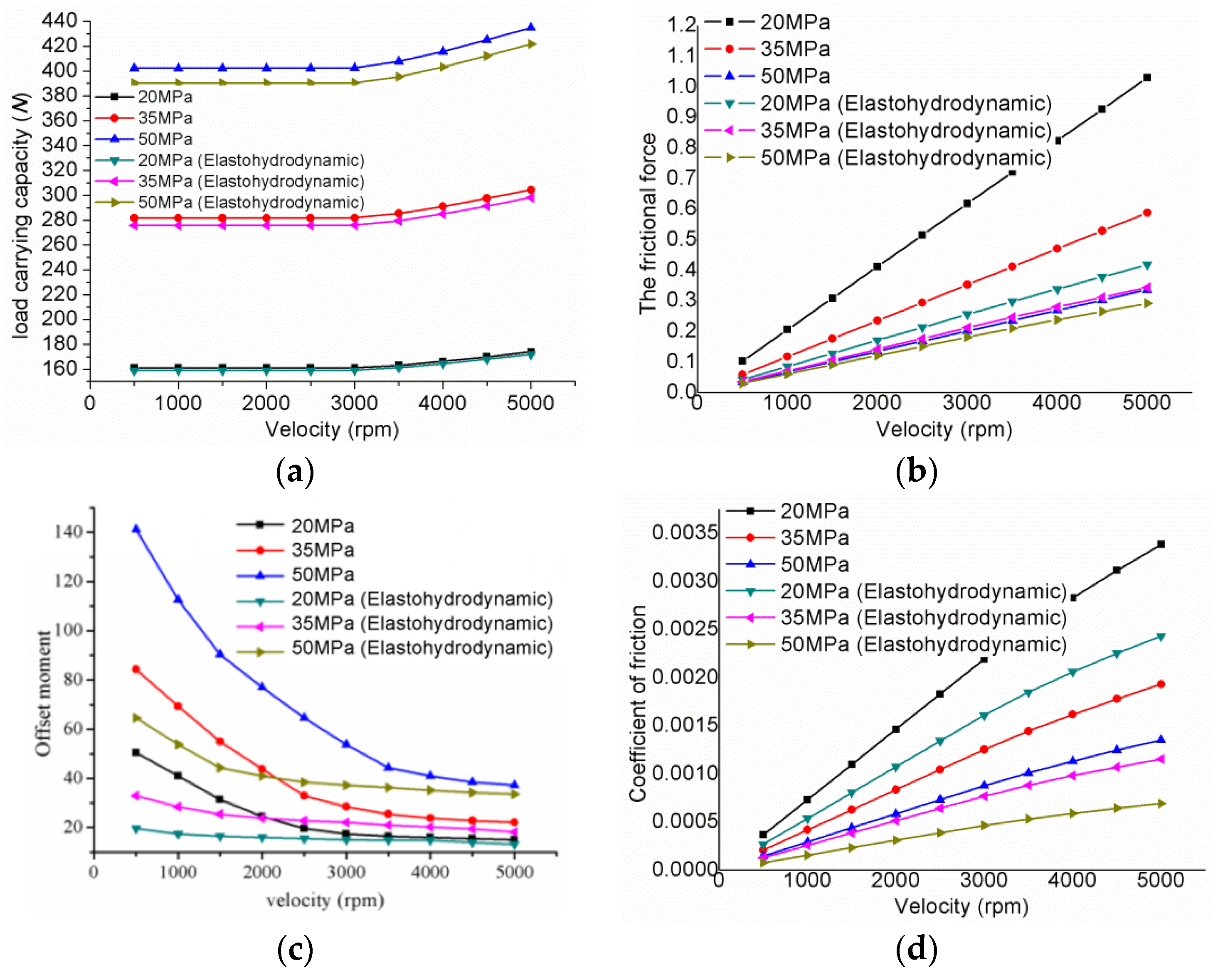
4.1. Influence of the Velocity on EHL Characteristics

Figure 8 shows the variation of oil film thickness with the velocity of rotation under elastic deformation: As the rotational velocity increases, the elastic deformation increases.
Figure 9 shows the effect of the velocity on the oil film clearance and pressure. The rotation velocity changes the oil film’s pressure distribution by generating a hydrodynamic pressure effect on the oil film. When the rotation velocity of the cylinder is increased, hydrodynamic pressure effects are more pronounced in the convergence region with a tiny wedge film thickness, which leads to an increase in the peak pressure and maximum oil film pressure in the convergence region.
Although the increase of the peak pressure will lead to more significant elastic deformation of the valve plate and thus increase the oil film thickness, the thickness change in the area of the minimum oil film thickness is three orders of magnitude smaller than that of the original film thickness and can be ignored.

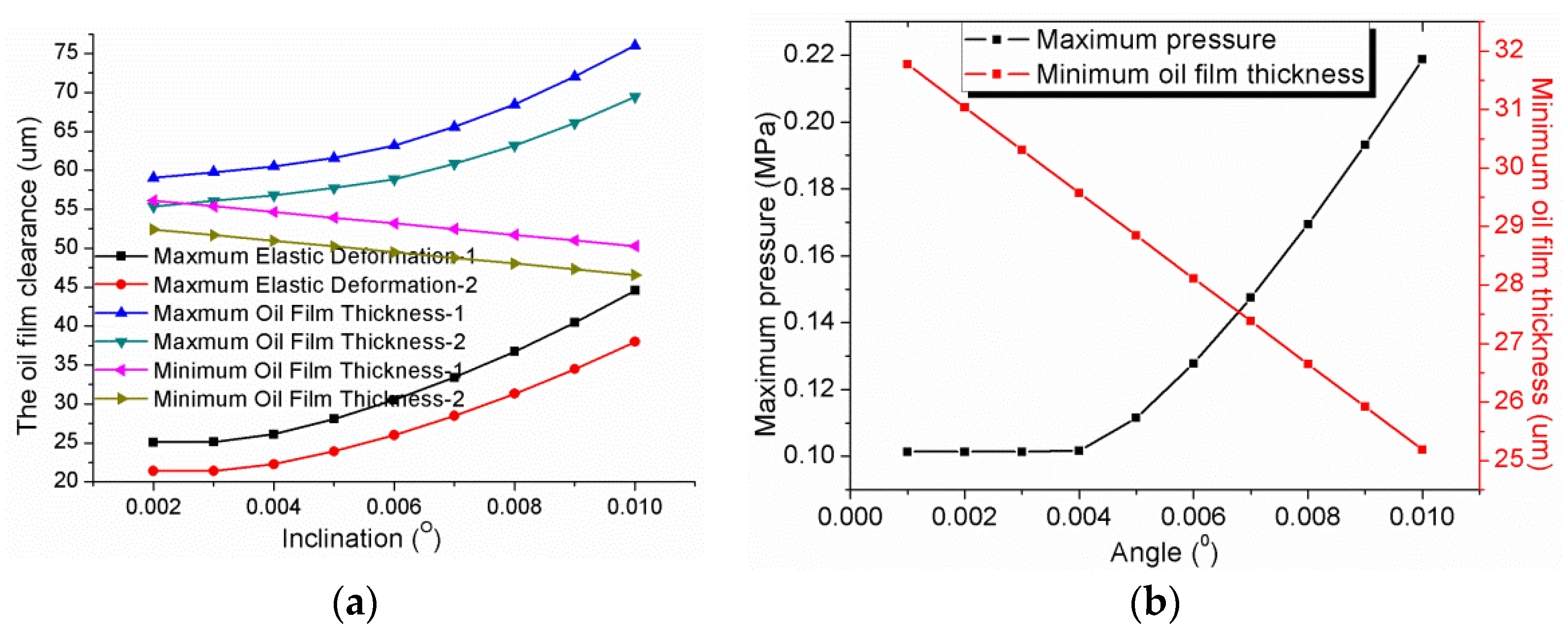
4.2. Influence of Cylinder Block Inclination on the EHL Characteristics

Figure 10 shows the variation of oil film thickness with inclination under elastic deformation: As the cylinder block inclination increases, the elastic deformation increases.
Figure 11 shows the effect of the inclination on the oil film clearance and pressure. The inclination of the cylinder block directly affects the angle of the lubricating film. The larger the inclination of the cylinder block, the larger the angle of the oil film, the larger the rate of film thickness change in the convergence zone, and the more pronounced the hydrodynamic pressure effect, which leads to an increase in the pressure peak value and the maximum pressure value of the oil film. At the same time, Equation (2) for the oil film thickness shows that the smaller the tilt angle of the cylinder, the smaller the minimum oil film thickness.

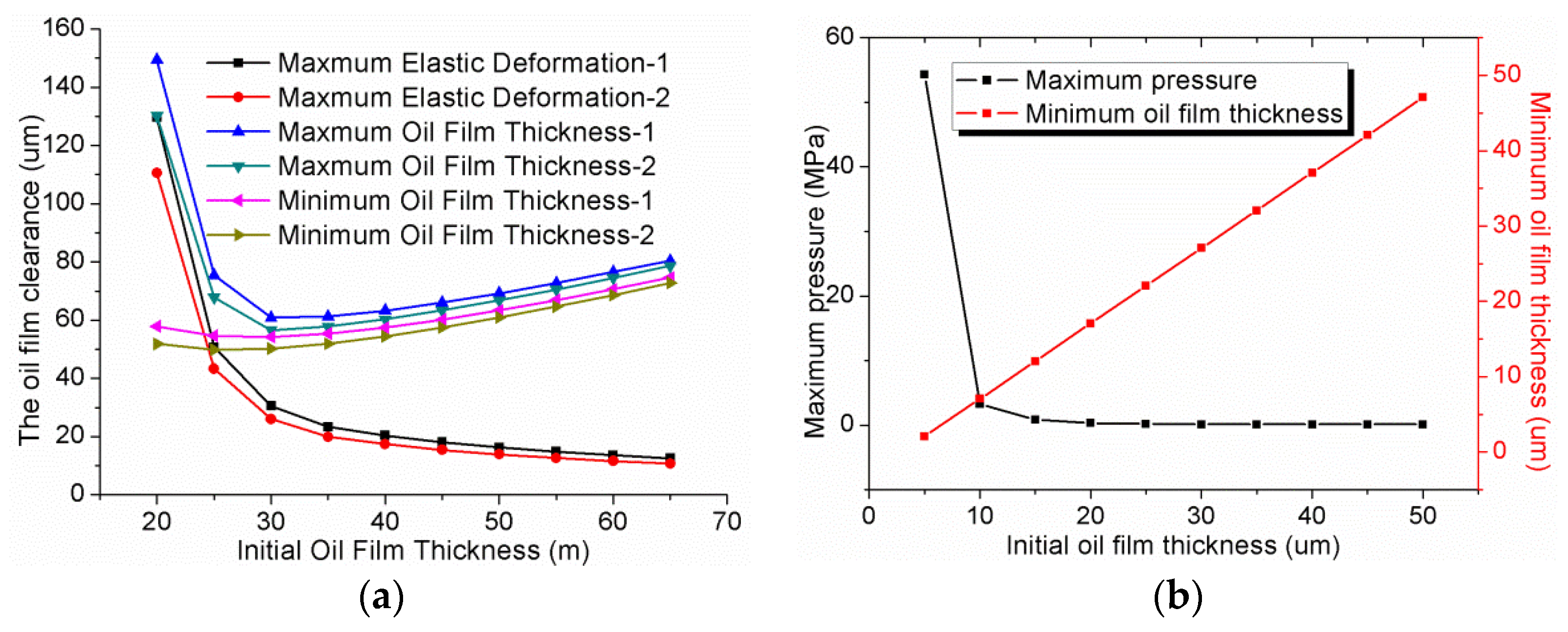
4.3. Influence of Initial Oil Film Thickness on the EHL Characteristics

Figure 12 shows the variation of oil film thickness with initial oil film thicknesses under elastic deformation: As the initial oil film thickness increases, the elastic deformation decreases.
Figure 13 shows the effect of the initial oil film thickness on the oil film clearance and pressure. On the one hand, the change in initial oil film thickness directly affects the distribution of oil film thickness to modify the solving process of the Reynolds equation, thus affecting the distribution of pressure. On the other hand, when the initial film thickness is increased, the film thickness in the convergence region of the wedge film increases simultaneously. In this case, the rate of film thickness change decreases, and the effect of hydrodynamic pressure becomes less pronounced. This will result in a decrease in the peak pressure and a decrease in the maximum oil film pressure.

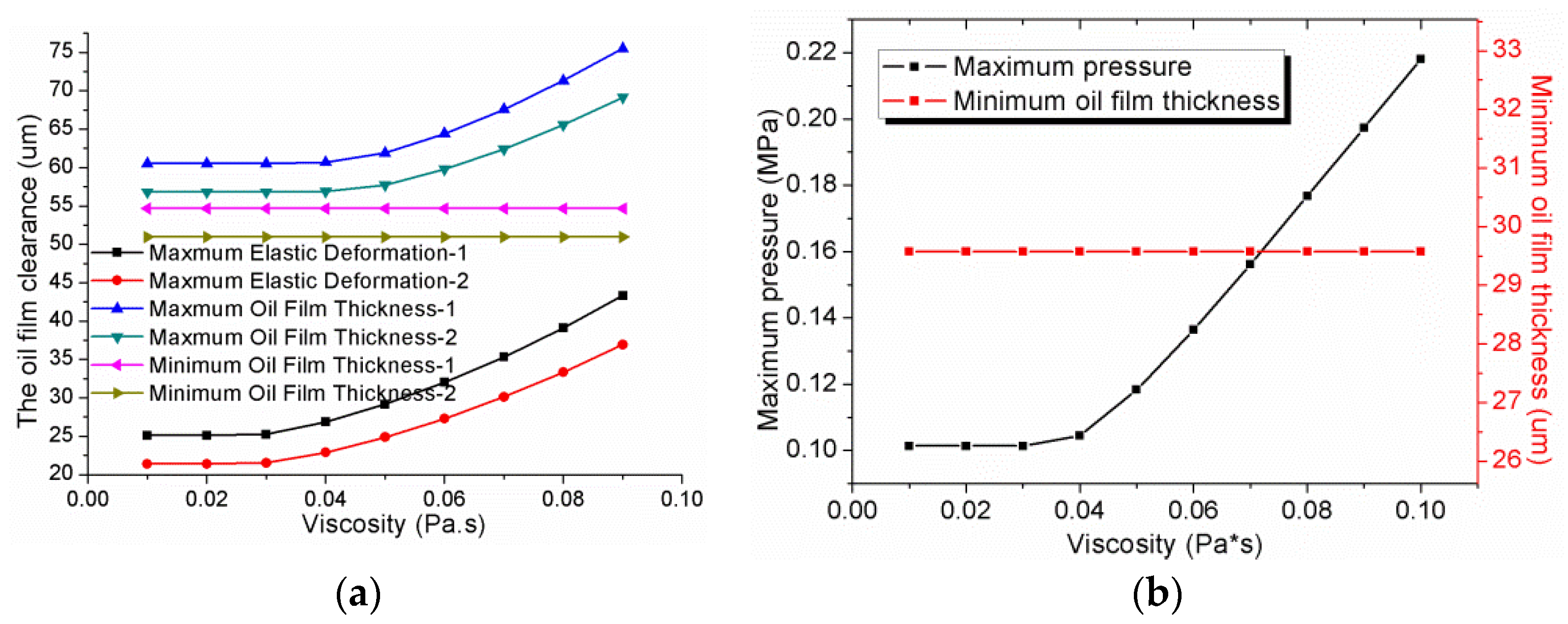
4.4. Influence of the Oil Film Viscosity on Elastohydrodynamic Characteristics

Figure 14 shows the variation of oil film thickness with viscosity under elastic deformation: as the oil film viscosity increases, the elastic deformation increases.
Figure 15 shows the effect of the viscosity on the oil film clearance and pressure. The lubricating oil viscosity is an essential factor affecting the hydrodynamic pressure effect. The hydrodynamic pressure effect becomes more pronounced when the lubricating oil viscosity increases, increasing the peak pressure and maximum oil film pressure values. The increase in the peak pressure will lead to an increase in the elastic deformation of the valve plate. However, the elastic deformation in the sealing area around the high-pressure oil port is tiny and negligible, so the minimum oil film thickness remains constant.

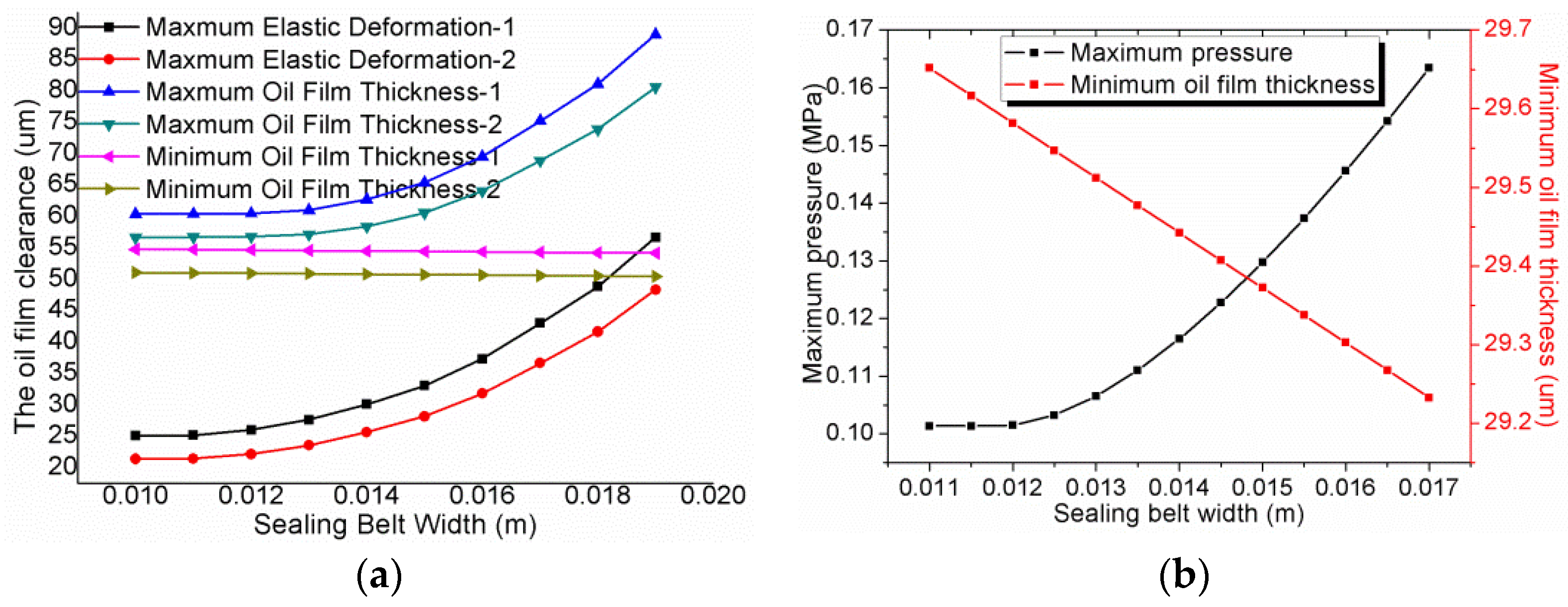
4.5. Influence of the Sealing Belt Width on EHL Characteristics

Figure 16 shows the variation of oil film thickness with sealing belt width under elastic deformation: As the width of the sealing belt increases, the elastic deformation increases.
Figure 17 shows the effect of the sealing belt width on the oil film clearance and pressure. As the width of the sealing belt increases, the area of the wedge-shaped oil film increases, which directly affects the thickness distribution of the oil film and changes the solution process of the Reynolds equation, which affects the pressure distribution. Consequently, the minimum oil film thickness also decreases, and the maximum pressure increases.

4.6. Comparison of the Operating Parameters on EHL Characteristics

The EHL characteristics of the contact surface of the port plate pair significantly impact the oil film’s overall performance. They are related to the port plate pair material, inlet pressure, velocity, and viscosity. Figure 8, Figure 9, Figure 10, Figure 11, Figure 12, Figure 13, Figure 14, Figure 15, Figure 16 and Figure 17 show the variation of the EHL characteristics with the operating parameters of the port plate pair. The elastic deformation value was magnified by 100 times for the convenience of observation.
(1)
The velocity of rotation: The tilt-gap dynamic pressure effect is evident when the cylinder block rotates at a high velocity. Dynamical pressure effects can only be formed when the two elements forming the seal gap form a relative motion and increase with increasing velocity.
(2)
The angle of inclination: The angle of inclination can change the oil film clearance. Dynamical pressure effects are evident as the tilt angle increases. The minimum film thickness is inversely proportional to the angle.
(3)
Initial oil film thickness: The initial oil film thickness between the cylinder and the valve plate can affect the oil film’s overall distribution and average stiffness. As the oil film becomes thinner, the pressure rises rapidly. The smaller the oil film gap, the larger the oil film squeeze, leading to more significant elastic deformation. The improper setting will fail to form a stable dynamic pressure effect, resulting in oil film rupture or leakage.
(4)
The lubricating oil viscosity: The dynamic pressure effect is evident as the viscosity increases. The greater the viscosity, the greater the shear force, higher pressure, and surface friction are formed, and the elastic deformation becomes more extensive and more profound.
(5)
Sealing belt width: The width of the valve plate’s inner and outer sealing belt can change the oil leakage speed, and the pressure gradient decreases along the width direction.

5. Lubricating Characteristics of the Port Plate Pair

The lubricating characteristics of the port plate pair were determined as the structural parameters were changed to obtain a comparative analysis.
Carrying capacity:
F = i = 1 n j = 1 m P i , j r i , j Δ θ Δ r
Offset load moment:
T 1 = i = 1 n j = 1 2 m P i , j r i , j 2 sin ( θ i , j ) Δ θ Δ r T 2 = i = 1 n j = 2 m m P i , j r i , j 2 cos ( θ i , j ) Δ θ Δ r T = T 1 T 2
Friction force:
F f = i = 1 n j = 1 m μ ω r i , j 2 h i , j Δ θ Δ r
Friction coefficient:
f = F f F
Leakage:
Q = φ h 3 12 μ Δ p ln R 2 R 1 + φ h 3 12 μ Δ p ln R 4 R 3

5.1. Calculation of Mechanical Lubrication Characteristics

The friction coefficient decreases significantly from boundary lubrication to mixed lubrication to dynamic lubrication to the EHL. The elastic deformation is neglected in dynamic pressure lubrication, and the elastic deformation and the viscosity pressure change are taken into account in the EHL. Figure 18 shows the variation of the lubrication property (carrying capacity, frictional force, offset load moment, friction coefficient) with speed.
The force of the port plate pair is not uniform to produce the unbalance load moment, and the low-pressure area friction lubrication effect is poor. The inlet pressure can increase the carrying capacity. Consider the EHL can reduce the bearing capacity, the friction, and the friction coefficient.

5.2. Calculation of Leakage Amount

The valve plate pair leakage is mainly divided into internal and external leakage, and the total leakage can reach 50% ~ 75% of the total leakage of the piston pump [40]. According to the theoretical model of leakage flow, the leakage flow of the valve plate pair is positively correlated with the velocity of the oil film along the radial direction, and the radial velocity of the oil film is correlated with the pressure of the oil film and the cylinder rotation speed. However, elastic deformation is closely related to these parameters. Therefore, the leakage of the valve plate pair needs to be analyzed in depth considering the elastic deformation to obtain the change rule of leakage under different parameters. Figure 19 shows the influence of different working conditions on the leakage quantity. In addition, it shows the comparison of leakage between the two groups of materials and whether elastic deformation is considered.
It can be seen from the figures that the valve plate pair leakage is closely related to the operating pressure and velocity, when the velocity and operating pressure are increased, the radial velocity of the oil increases, which improves the leakage.
The larger the inclination of the cylinder block, the larger the rate of film thickness change in the convergence zone, and the more pronounced the hydrodynamic pressure effect, which leads to an increase in the leakage.
Initial oil film thickness, either too thick or too thin, will cause elastic deformation and lead to increased leakage. However, the influence of elastic deformation can be ignored when the initial oil film thickness exceeds 30 um.
Too thin viscosity causes too thin minimum film thickness, causing severe leakage and elastic deformation, resulting in oil film rupture and unable to form full film lubrication.
A severe leak will cause the piston pump to fail to work thoroughly. Inadequate leakage will lead to insufficient lubrication of the port plate pair, forming direct contact solid friction between the cylinder block and the valve plate, producing high temperature, and significantly reducing the service life of the port plate pair.

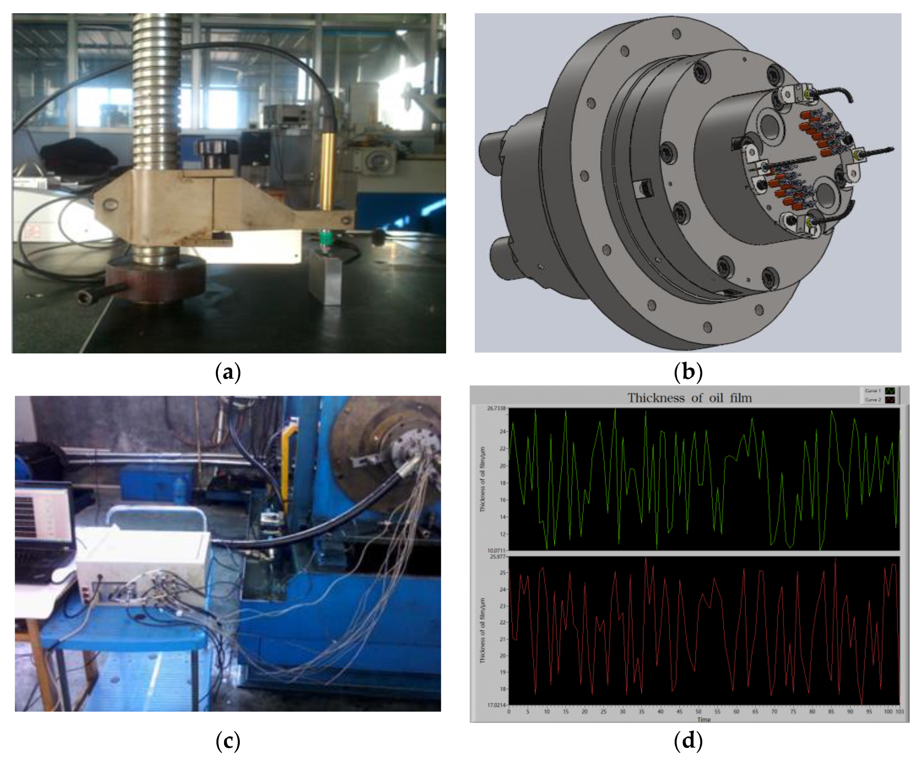
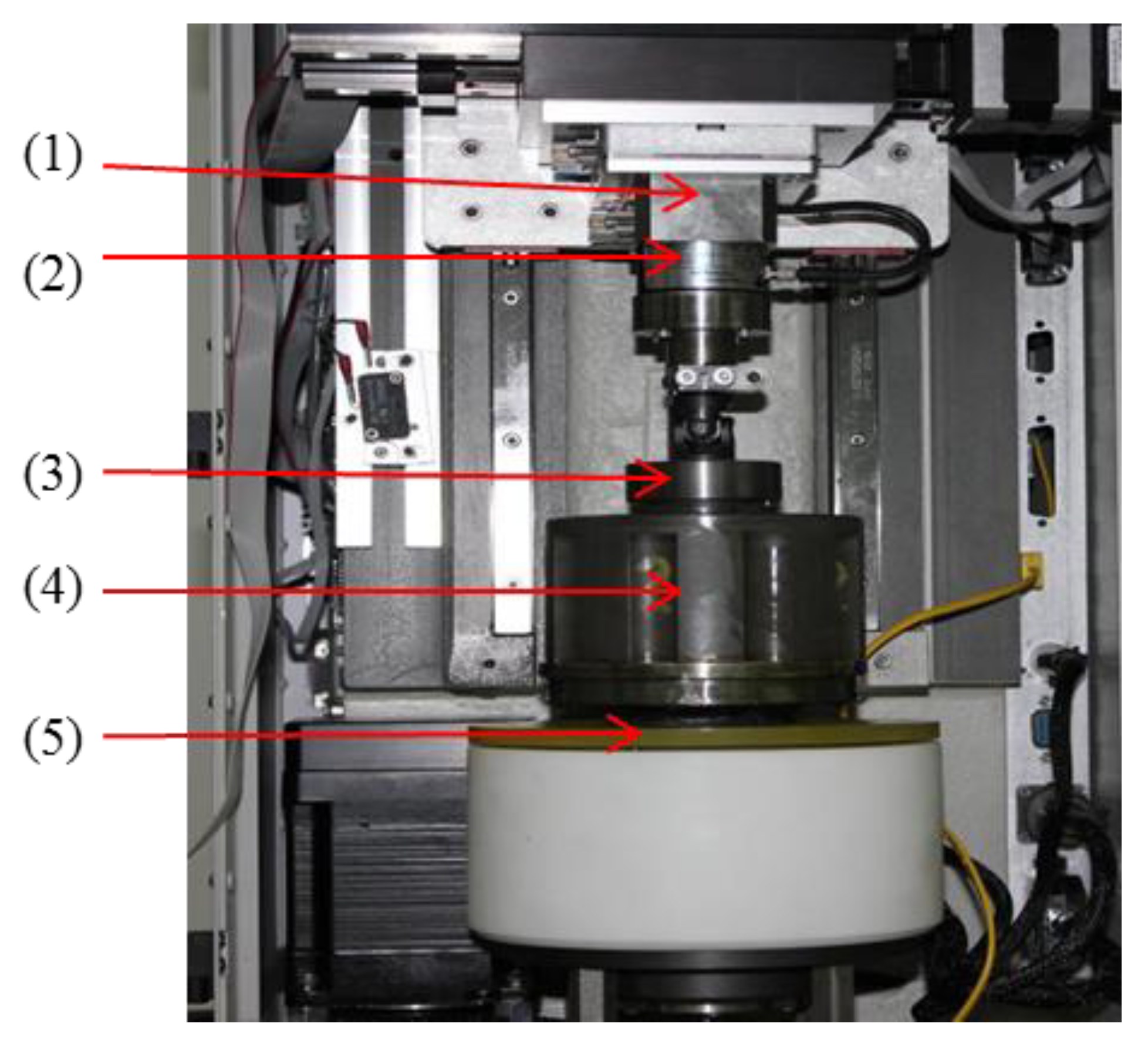
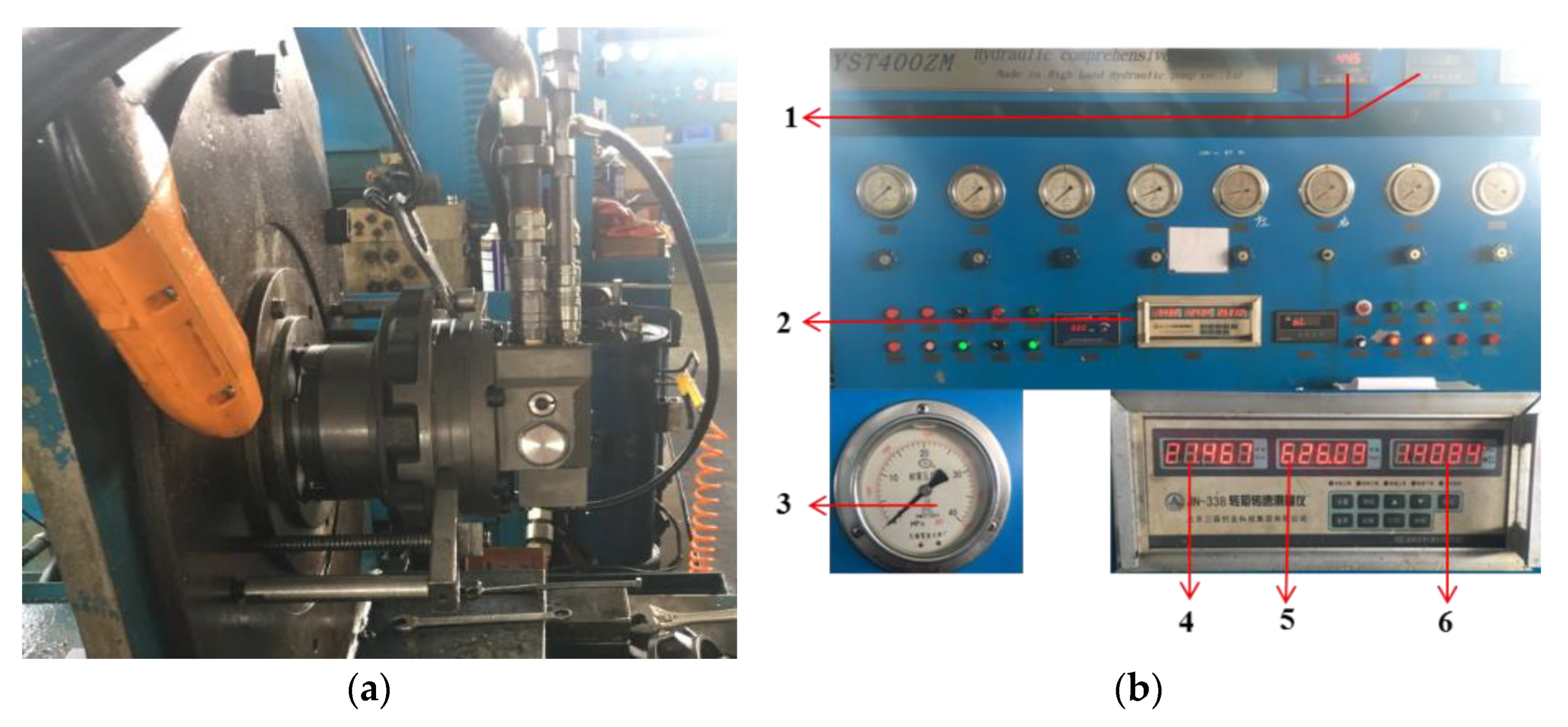
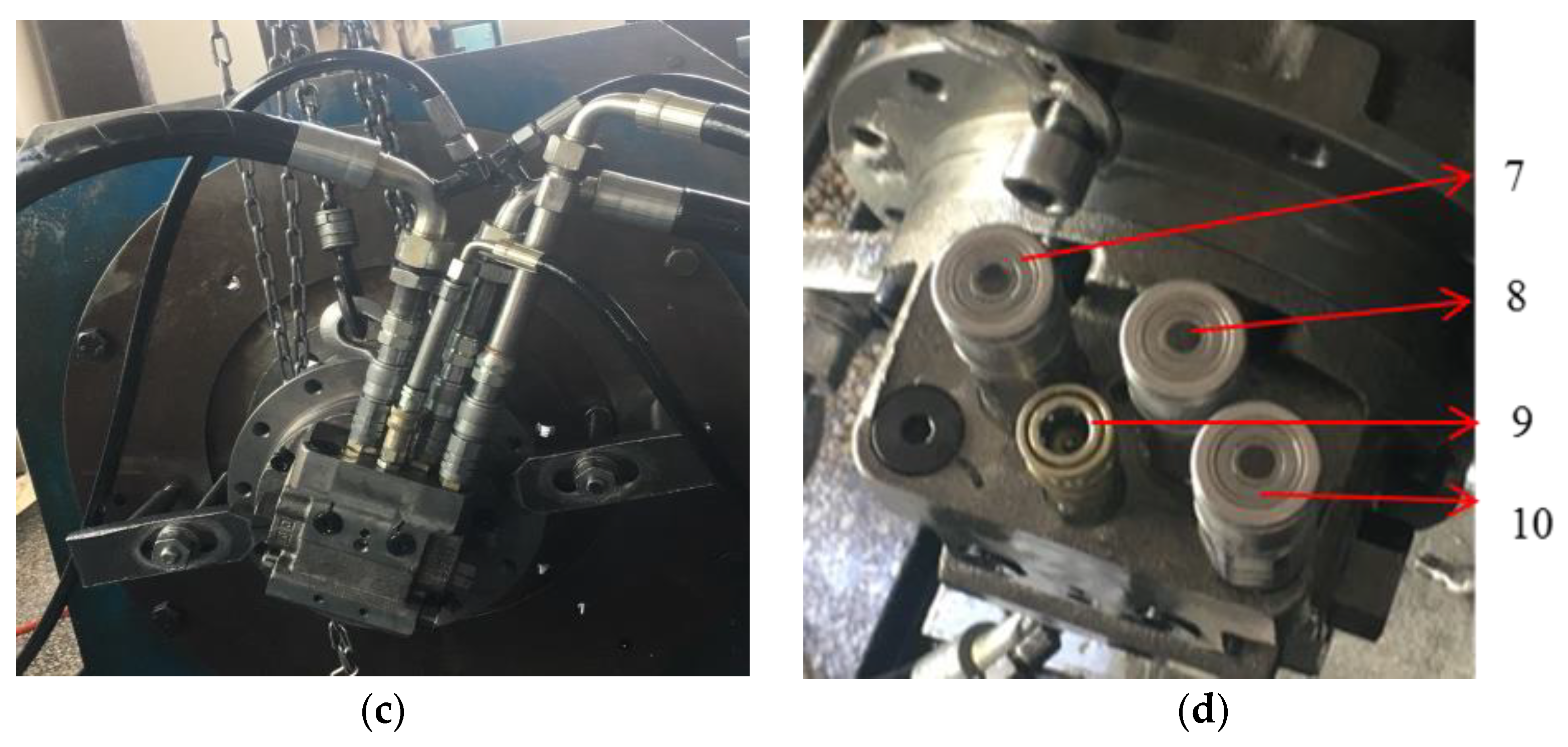
6. Oil Film Lubrication Characteristics Experiment of Port Plate Pair

Figure 20, Figure 21, Figure 22 and Figure 23 shows the experiment of the oil film thickness test; Figure 24, Figure 25 and Figure 26 shows the experiment of friction coefficient test; Figure 27 and Figure 28 shows the experiment of leakage and moment.

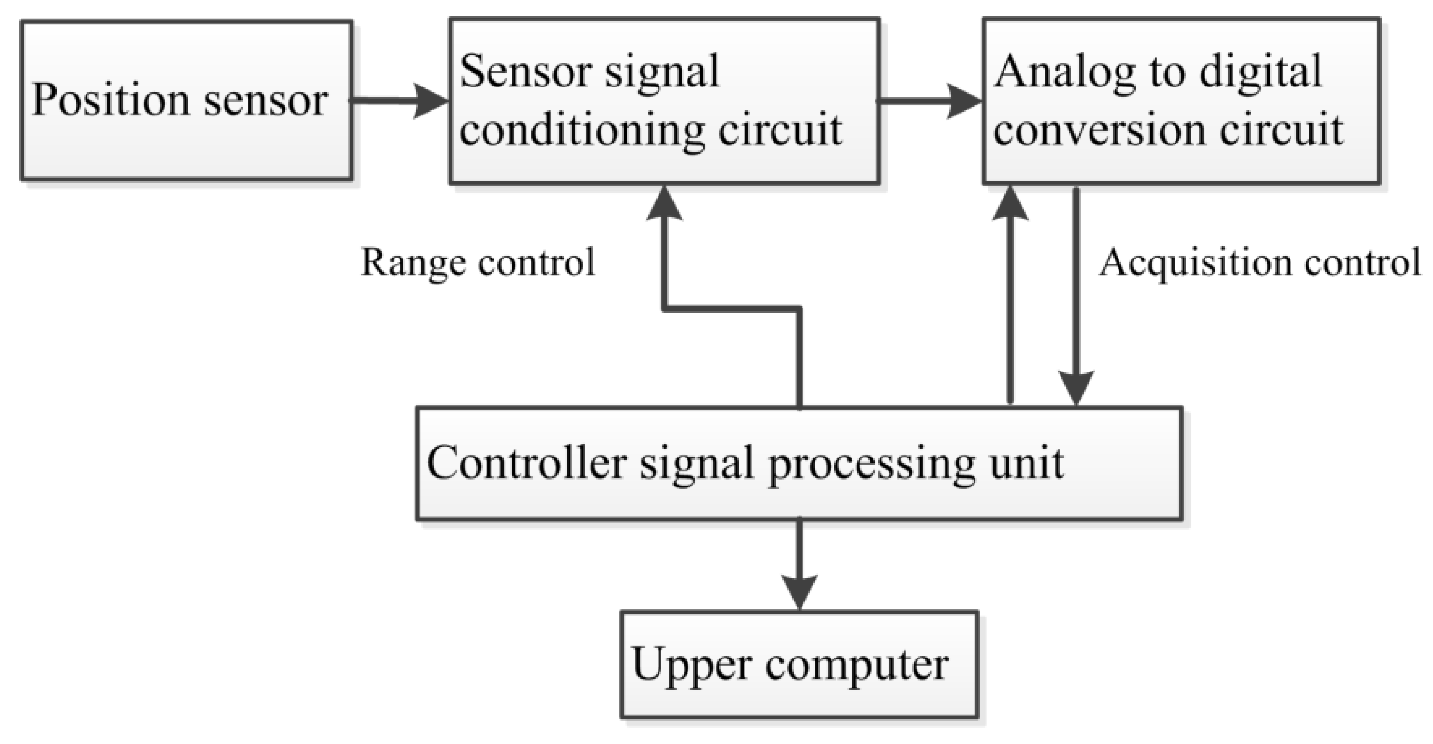
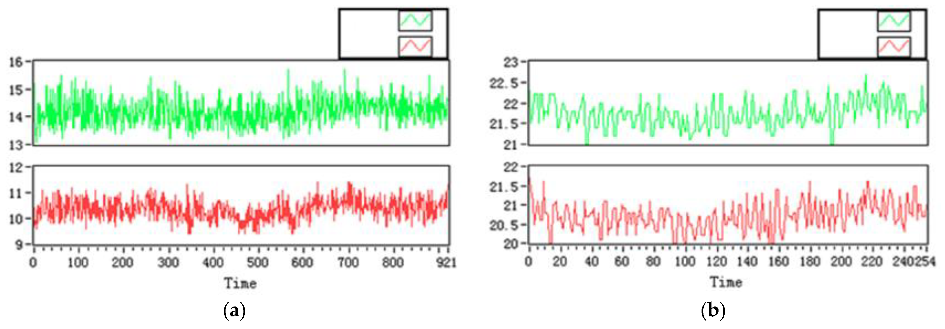
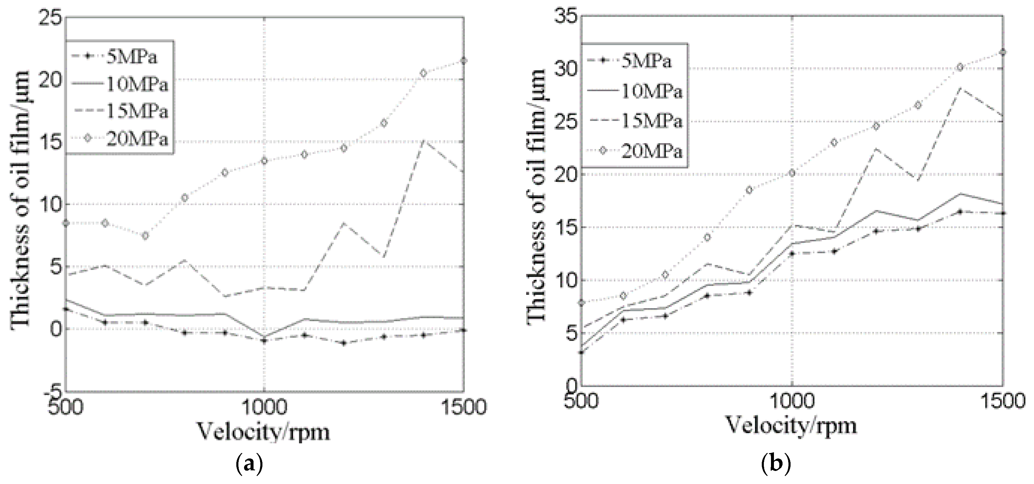
6.1. Experiment on Measuring the Oil Film Thickness of Port Plate Pair

Figure 20 shows the device for testing the oil film thickness. The upper computer software adopts LabVIEW for online measurement and data collection.
Figure 21 shows the schematic diagram of the internal circuit for measuring the displacement by the inductive micro-displacement sensor. The data are transmitted and displayed after communicating with the upper computer through the RS232 interface.
Figure 22 shows the oil film thickness test curve of the port plate pair at 1000 rpm and 20 MPa. Figure 22a is the oil film thickness at the oil inlet of the port plate pair. Figure 22b is the oil film thickness of the oil outlet. The upper side or lower side represents the position of the upper side or lower side of the kidney-shaped slot.
Figure 23 shows the oil film thickness experimental statistical curve under different pressures. From the experimental statistical data, the oil film thickness of the inlet is smaller than that of the outlet because the oil film was squeezed due to the pressure rise of the inlet pressure. The oil film thickness increases with the increase in rotating speed. At the same speed, the oil film thickness decreases with the pressure increasing. This also proves why the leakage increases when the oil pressure rises.

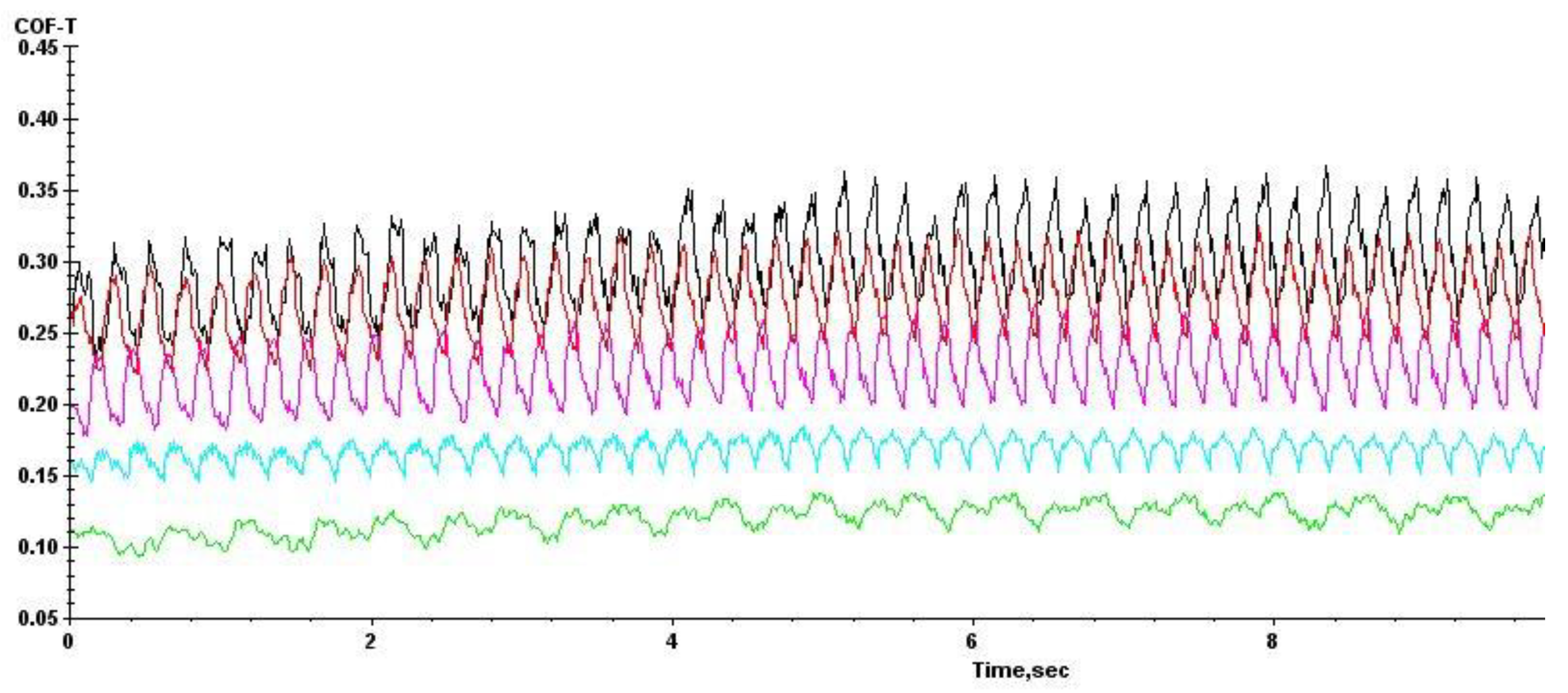
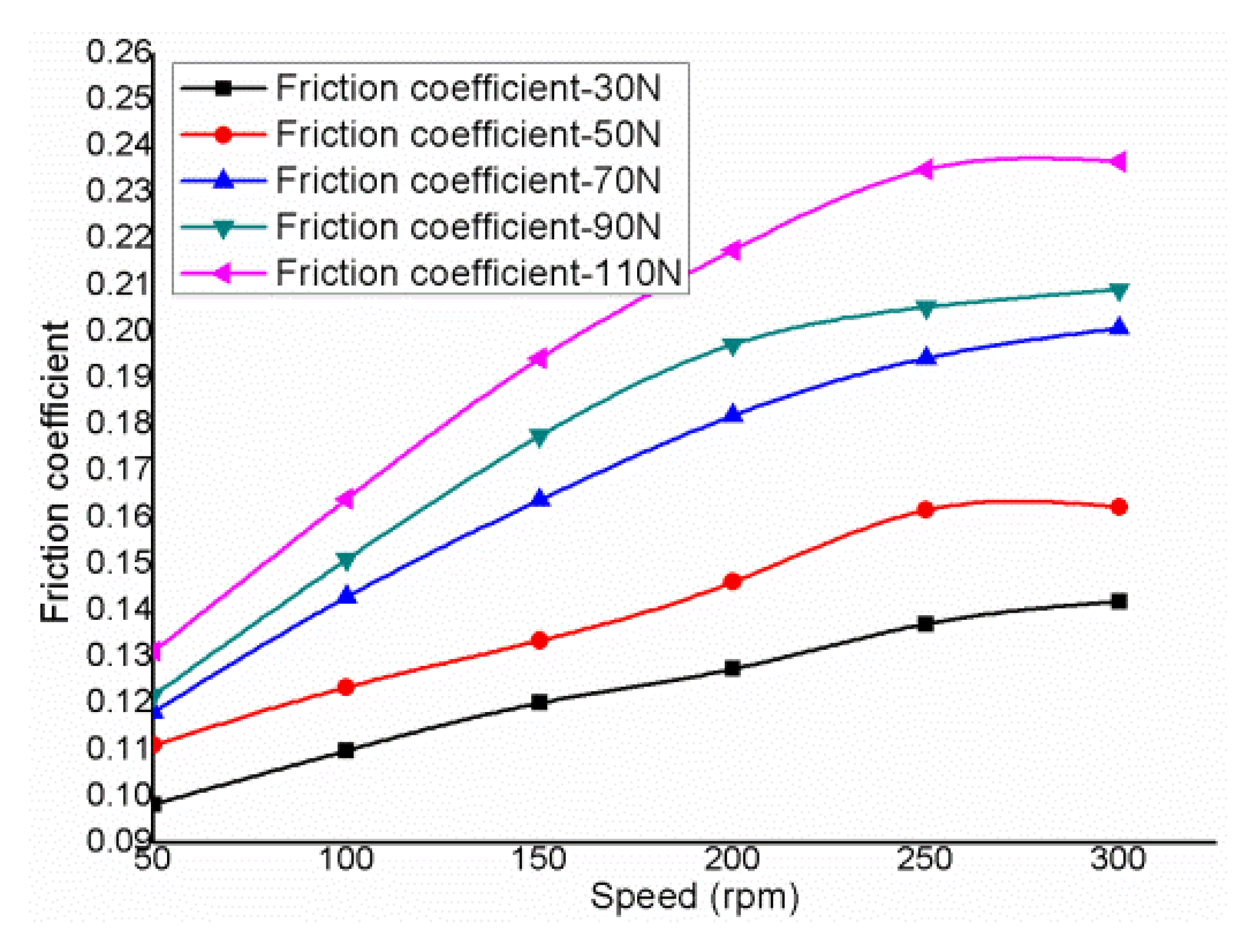
6.2. Experiment of Friction Coefficient

Figure 24 shows the setup for testing the friction coefficient for the valve plate on CETR UMT-3 (Type of Rub Tester): the speed of the friction test machine increased from 50 rpm to 300 rpm during operation.
Figure 25 shows the test curve for the friction coefficient for the valve plate on CETR UMT-3 as the pressure under 110 N, and the speed of the friction test machine increased from 50 rpm to 300 rpm; it partially demonstrates the increase in friction coefficient with increasing cylinder speed.
Figure 26 shows the test curve obtained for the friction coefficient for the valve plate as the pressure increased from 30 N to 110 N. In general, the cylinder speed increase can improve the oil film bearing capacity, the lubrication performance, and the oil film stiffness, which is conducive to reducing the piston pump operation process due to the cylinder and the contact with the plate pair caused by friction wear. However, at the same time, the increase in cylinder speed also brings friction, friction torque, and friction coefficient increases, which will reduce friction efficiency. These results are consistent with the trend in Figure 18.

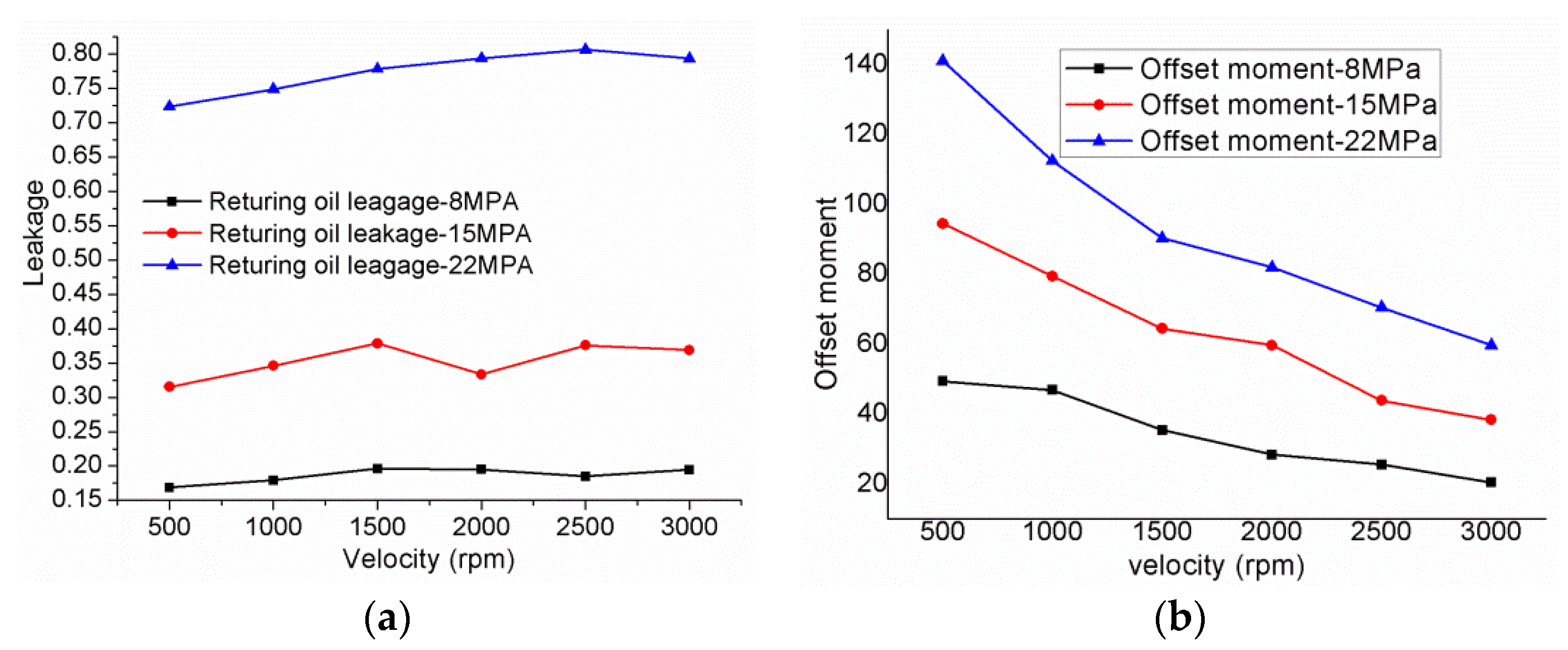
6.3. Leakage and Torque Experiments

Figure 27 shows the leakage of the port plate pair and the torque of the piston pump experimental device. Figure 27a is the side view of the experimental device; Figure 27b is an instrument display device; Figure 27c is the experimental installation diagram of the port plate pair; Figure 27d is the oil mouth device. The offset load torque and leakage are tested by changing the piston pump speed from 500 rpm to 3000 rpm. Due to the experimental conditions, the maximum speed is less than 3000 rpm.
Figure 28 shows the experimental data of leakage and torque. The increase in rotational velocity and working pressure will promote an increase in the radial velocity of the oil, thus increasing the leakage quantity of the port plate pair, as shown in Figure 28a. On the other hand, as the rotation speed increases, the piston pump’s torque decreases, as shown in Figure 28b. Therefore, the trends of the leakage and offset load torque experiments match those of the theoretical calculations.

7. Conclusions

In this paper, an EHL model is adopted to study the lubrication characteristics of two different port plate pairs on the interface of the axial piston pump under certain working conditions. The results show that the elastic deformation of the contact and sliding interfaces greatly influences the film’s overall performance.
(1)
The pressure field can be changed by the transient deformation change caused by pressure. The simulation results show that transient deformation extrusion pressure affects the overall fluid film thickness. Furthermore, the wedge gap between the cylinder block and the valve plate produces mixed friction.
(2)
The simulation results show that the fluid film of design 2 (as shown in Table 2) has better stability, thinner fluid film, and more minor deformation, which ensures the whole film’s hydrodynamic lubrication and improves the sealing performance. For the cylinder body/valve plate interface performance to be stable and reliable, it is necessary to conduct the structural design and material properties.
(3)
The deformation due to fluid pressure significantly impacts the modeling leakage and the friction coefficient, especially when the deformation magnitude becomes comparable to the oil film clearance. Due to the reduction in static pressure bearing capacity, friction force, and friction coefficient caused by elastic deformation, a large amount of hydrodynamic pressure production is needed. The EHL effect is evident at the convergence of oil film.
(4)
Under high load and high speed, the rotation of the cylinder block affects the oil pressure field of port plate pairs. The local pressure peak affects the elastic deformation of the cylinder body/valve plate, which improves the EHL effect. In addition, because of the EHL effect, the back edge of the valve plate is lifted off the cylinder block, effectively maintaining the film thickness.
(5)
The oil film elastic deformation is related to the structural parameters of the piston pump, working conditions parameters of the piston pump and lubrication parameters of the oil film. However, further simulations and experimental verification are required to provide a theoretical basis for a high-speed and high-pressure piston pump. The calculated friction coefficient and offset load torque showed good qualitative and quantitative agreement with the measurements. A discrepancy between experimental and simulation results could have been caused by the restrictions imposed by the conditions used in the experiment since the pump can only change the speed, lubricating oil viscosity, and inlet pressure during the experiment.

Author Contributions

Z.W. was in charge of the establishment of the model and the whole trial; B.H. and L.S. wrote the manuscript; B.H. and L.S. assisted with experimentation. All authors have read and agreed to the published version of the manuscript.

Funding

This study was funded by Project Nos. 51505272, 51505274 and 51876113, supported by the National Natural Science Foundation of China and Project No. GZKF-201514, supported by the Open Foundation of the State Key Laboratory of Fluid Power and Mechatronic Systems.

Institutional Review Board Statement

Not applicable.

Informed Consent Statement

Not applicable.

Data Availability Statement

Not applicable.

Conflicts of Interest

The authors declare that they have no known competing financial interest or personal relationship that could have influenced the work reported in this paper.

Nomenclature

SymbolNameSymbolName
hOil film thickness (m).PWorking pressure (Pa).
h 0 Initial oil film thickness. p 0 Standard atmospheric pressure
h c Oil film thickness without deformation.ηLubricating oil viscosity (Pa·s).
vElastic deformation (μm). η 0 Initial oil film viscosity.
v ( x , y ) Elastic deformation displacement caused by pressure.θCircumferential angle(°).
p i , j Pressure   at   node   ( i , j ) .δDeformation displacement.
ΩSolution domain. δ k l Elastic deformation at node (k, l).
a i k , j l The   integral   coefficient   of   the   D i j k l δ i j Elastic   deformation   at   node ( x i , y j ) .
p k l Pressure   at   node .   ( x k , y l )
D i j k l The amount of deformation produced on the node k, l. δ 1 Deformation displacement of valve plate (μm).
R 1 Inner diameter (interior sealing belt). δ 2 Deformation displacement of cylinder block (μm).
R 2 Outer diameter (interior sealing belt).ωVelocity of rotation.
R 3 Inner diameter (outer sealing belt).φTilt angle
R 4 Outer diameter (outer sealing belt).BSealing belt width (m).
E Comprehensive elastic modulus (Pa). V 1 Poisson’s ratio for valve plate.
E 1 Elastic modulus of valve plate (Pa). V 2 Poisson’s ratio for cylinder block.
E 2 Elastic modulus of cylinder block (Pa).fFriction coefficient.
FCarrying capacity (N).QLeakage (L/min).
TOffset load torque (N · m). F f Friction force (N).

References

  1. Ye, S.; Zhang, J.; Xu, B.; Hou, L.; Xiang, J.; Tang, H. A Theoretical Dynamic Model to Study the Vibration Response Characteristics of an Axial Piston Pump. Mech. Syst. Signal Process. 2021, 150, 107237. [Google Scholar] [CrossRef]
  2. Chen, Y.; Zhang, J.; Xu, B.; Chao, Q.; Liu, G. Multi-Objective Optimization of Micron-Scale Surface Textures for the Cylinder/Valve Plate Interface in Axial Piston Pumps. Tribol. Int. 2019, 138, 316–329. [Google Scholar] [CrossRef]
  3. Bae, J.-H.; Chung, W.-J.; Jang, J.-H.; Yoon, Y.-H.; Jeon, J.-Y. Study of Pressure and Flux Pulsation to Design Optimum Valve-Plate Notch and Pulsation-Variables Analysis of Swash-Plate-Type Piston Pump. J. Korean Soc. Manuf. Technol. Eng. 2015, 24, 244–250. [Google Scholar] [CrossRef] [Green Version]
  4. Zloto, T.; Nagórka, A. Analysis of the Pressure Distribution of Oil Film in the Variable Height Gap between the Valve Plate and Cylinder Block in the Axial Piston Pump. TEKA Kom. Mot. Energ. Roln. OL PAN 2007, 7, 293–301. [Google Scholar]
  5. Zloto, T.; Sochacki, D.; Stryjewski, P. Analysis of Oil Leaks in a Variable-Height Gap between the Cylinder Block and the Valve Plate in a Piston Pump by Means of Author-Designed Software and CFD Fluent. Teka Kom. Motoryz. I Energetyki Rol. 2014, 14, 211–216. [Google Scholar]
  6. Zhu, Y.; Chen, X.; Zou, J.; Yang, H. A Study on the Influence of Surface Topography on the Low-Speed Tribological Performance of Port Plates in Axial Piston Pumps. Wear 2015, 338–339, 406–417. [Google Scholar] [CrossRef]
  7. Wang, S. Robust Design of Piston Assemblies in an Axial Piston Pump. Int. J. Fluid Power 2014, 15, 69–76. [Google Scholar] [CrossRef]
  8. Zloto, T. Simulation of the Hydrostatic Load of the Valve Plate-Cylinder Block System in an Axial Piston Pump. Procedia Eng. 2017, 177, 247–254. [Google Scholar] [CrossRef]
  9. Ivantysynova, M. A New Approach to the Design of Sealing and Bearing Gaps of Displacement Machines. Proc. JFPS Int. Symp. Fluid Power 1999, 1999, 45–50. [Google Scholar] [CrossRef] [Green Version]
  10. Lijesh, K.P.; Amirthagadeswaran, K.S. Optimizing Interlayer and Coated Film Thickness for Minimum Stress Distribution under Elastohydrodynamic Lubrication Condition. In Proceedings of the Frontiers in Automobile and Mechanical Engineering-2010, Chennai, India, 25–27 November 2010; pp. 328–334. [Google Scholar]
  11. Chao, Q.; Zhang, J.; Xu, B.; Wang, Q. Discussion on the Reynolds Equation for the Slipper Bearing Modeling in Axial Piston Pumps. Tribol. Int. 2018, 118, 140–147. [Google Scholar] [CrossRef]
  12. Zhao, J.; Fu, Y.; Ma, J.; Fu, J.; Chao, Q.; Wang, Y. Review of Cylinder Block/Valve Plate Interface in Axial Piston Pumps: Theoretical Models, Experimental Investigations, and Optimal Design. Chin. J. Aeronaut. 2021, 34, 111–134. [Google Scholar] [CrossRef]
  13. Zecchi, M.; Ivantysynova, M. A Novel Fluid Structure Interaction Model for the Cylinder Block/Valve Plate Interface of Axial Piston Machines. In Proceedings of the 52nd National Conference on Fluid Power, Las Vegas, NV, USA, 23–25 March 2011; pp. 23–25. [Google Scholar]
  14. Achten, P.A.J.; Schellekens, M.P.A. Deformation Effects on the Load Carrying Capacity of the Barrel Bearing in Axial Piston Pumps and Motors. In Proceedings of the IMECE2006, Fluid Power Systems and Technology, Chicago, IL, USA, 5–10 November 2006; pp. 9–21. [Google Scholar]
  15. Manring, N.D.; Johnson, R.E.; Cherukuri, H.P. The Impact of Linear Deformations on Stationary Hydrostatic Thrust Bearings. J. Tribol. 2002, 124, 874–877. [Google Scholar] [CrossRef]
  16. Lin, X.; Jiang, S.; Zhang, C.; Liu, X. Thermohydrodynamic Analysis of High Speed Water-Lubricated Spiral Groove Thrust Bearing Considering Effects of Cavitation, Inertia and Turbulence. Tribol. Int. 2018, 119, 645–658. [Google Scholar] [CrossRef]
  17. Brown, S.R.; Hamilton, G.M.; Moore, S.L. Hydrodynamic Pressure under a Piston Ring. Nature 1975, 253, 341–342. [Google Scholar] [CrossRef]
  18. Johnson, K.L.; Roberts, A.D. Rheology of Oil Films at High Contact Pressures. Nature 1972, 240, 553–554. [Google Scholar] [CrossRef]
  19. Yamaguchi, A. Pressure Distribution on Valve Plate of Axial Plunger Pumps and Motors. Prod. Res. 1966, 18, 186–188. [Google Scholar]
  20. Yamaguchi, A.; Fujitani, Y.; Isoda, Y. Characteristics of Fluid Film between a Valve Plate and a Cylinder Block of Axial Piston Pumps and Motors. Hydraul. Pneum. 1984, 15, 64–72. [Google Scholar]
  21. Yamaguchi, A. Formation of a Fluid Film between a Valve Plate and a Cylinder Block of Piston Pumps and Motors: 2nd Report, A Valve Plate with Hydrostatic Pads: Heat Transfer, Combustion, Power, Thermophysical Properties. JSME Int. J. 1987, 30, 87–92. [Google Scholar] [CrossRef] [Green Version]
  22. Pan, H.; Sheng, J.; Lu, Y. Finite Difference Computation of Valve Plate Fluid Film Flows in Axial Piston Machines. Int. J. Mech. Sci. 1989, 31, 779–791. [Google Scholar] [CrossRef]
  23. Bergada, J.M.; Kumar, S.; Davies, D.L.; Watton, J. A Complete Analysis of Axial Piston Pump Leakage and Output Flow Ripples. Appl. Math. Model. 2012, 36, 1731–1751. [Google Scholar] [CrossRef]
  24. Huang, C. A New Approach to Predict the Load Carrying Ability of the Gap between Valve Plate and Cylinder Block. In Proceedings of the Bath Workshop of Power Transmission and Motion Control PTMC 2003, Bath, UK, 24 October 2003; pp. 225–239. [Google Scholar]
  25. Wang, B.; Zhou, H.; Yang, H. Real-Time Measurement on Lubrication Characteristic Parameters of Plane Port Pair in Axial Piston Pumps. Nongye Jixie Xuebao/Trans. Chin. Soc. Agric. Mach. 2009, 40, 170–213. [Google Scholar]
  26. Lin, S.; Hu, J. Tribo-Dynamic Model of Slipper Bearings. Appl. Math. Model. 2015, 39, 548–558. [Google Scholar] [CrossRef]
  27. Li, Y.; Ji, Z.; Yang, L.; Zhang, P.; Xu, B.; Zhang, J. Thermal-Fluid-Structure Coupling Analysis for Valve Plate Friction Pair of Axial Piston Pump in Electrohydrostatic Actuator (EHA) of Aircraft. Appl. Math. Model. 2017, 47, 839–858. [Google Scholar] [CrossRef]
  28. Pelosi, M.; Ivantysynova, M. A Novel Thermal Model for the Piston/Cylinder Interface of Piston Machines. In Proceedings of the DSCC2009, ASME 2009 Dynamic Systems and Control Conference, Hollywood, CA, USA, 12–14 October 2009; Volume 2, pp. 37–44. [Google Scholar]
  29. Schenk, A.; Ivantysynova, M. A Transient Thermoelastohydrodynamic Lubrication Model for the Slipper/Swashplate in Axial Piston Machines. J. Tribol. 2015, 137, 31701. [Google Scholar] [CrossRef]
  30. Shang, L.; Ivantysynova, M. Port and Case Flow Temperature Prediction for Axial Piston Machines. Int. J. Fluid Power 2015, 16, 35–51. [Google Scholar] [CrossRef]
  31. Tang, H.; Ren, Y.; Xiang, J. A Novel Model for Predicting Thermoelastohydrodynamic Lubrication Characteristics of Slipper Pair in Axial Piston Pump. Int. J. Mech. Sci. 2017, 124–125, 109–121. [Google Scholar] [CrossRef]
  32. Qian, P.; Pu, C.; Liu, L.; Li, X.; Zhang, B.; Gu, Z.; Meng, D. Development of a New High-Precision Friction Test Platform and Experimental Study of Friction Characteristics for Pneumatic Cylinders. Meas. Sci. Technol. 2022, 33, 65001. [Google Scholar] [CrossRef]
  33. Qian, P.; Pu, C.; Liu, L.; Lv, P.; Ruiz Páez, L.M. A Novel Pneumatic Actuator Based on High-Frequency Longitudinal Vibration Friction Reduction. Sens. Actuators A: Phys. 2022, 344, 113731. [Google Scholar] [CrossRef]
  34. Qian, P.; Pu, C.; He, D.; Lv, P.; Ruiz Páez, L.M. A Method to Improve the Motion Trajectory Tracking Accuracy of Pneumatic Servo System—By Exciting Longitudinal Resonance. J. Braz. Soc. Mech. Sci. Eng. 2022, 44, 376. [Google Scholar] [CrossRef]
  35. Edge, K.A.; Darling, J. The Pumping Dynamics of Swash Plate Piston Pumps. J. Dyn. Syst. Meas. Control 1989, 111, 307–312. [Google Scholar] [CrossRef]
  36. Brooks, D.W. Valve Plate for Axial Hydraulic Piston Pump or Motor. U.S. Patent 20,030,126,982, 1 January 2002. Available online: https://www.freepatentsonline.com/y2003/0126982.html (accessed on 10 July 2003).
  37. Nunomura, H. High-Pressure and Low-Pressure Selecting Valve and Swash-Plate Type Hydraulic Motor System. U.S. Patent 20,040,000,142, 27 June 2002. Available online: https://www.freepatentsonline.com/y2004/0000142.html (accessed on 1 January 2004).
  38. Wieczorek, U.; Ivantysynova, M. Computer Aided Optimization of Bearing and Sealing Gaps in Hydrostatic Machines—The Simulation Tool Caspar. Int. J. Fluid Power 2002, 3, 7–20. [Google Scholar] [CrossRef]
  39. Huang, P. Numerical Calculation of Elastohydrodynamic Lubrication: Methods and Programs; John Wiley & Sons: Hoboken, NJ, USA, 2015; ISBN 1-118-92098-8. [Google Scholar]
  40. Zhang, Y.; Zhang, H.; Zhao, Q.; Wang, X.; Zhang, T. Simulation of Pump Chamber Flow Field for Rotating-Sleeve Distributing-Flow System for Reciprocating Plunger Pump. Chin. Hydraul. Pneum. 2016, 11, 31–35. [Google Scholar]
Figure 1. The model of port plate pair for piston pump. (a) The assembly diagram of the valve plate and cylinder block; (b) A schematic diagram of the valve plate.
Machines 10 01109 g001
Figure 2. The EHL model for point and surface contact. (a) Elastic deformation of point contact; (b) elastic deformation of surface contact.
Machines 10 01109 g002
Figure 3. Isothermal EHL calculation block diagram.
Machines 10 01109 g003
Figure 4. Oil film thickness distribution: (a) three-dimensional diagram of oil film distribution; (b) top view of wedge oil film thickness.
Machines 10 01109 g004
Figure 5. Oil film pressure distribution (a) pressure distribution 3D diagram; (b) pressure distribution top view; (c) pressure distribution 3D diagram under 35 MPa; (d) pressure distribution top view under 35 MPa.
Machines 10 01109 g005
Figure 6. Elastic deformation distribution of oil film (a) elastic deformation distribution; (b) elastic deformation distribution under 35 MPa.
Machines 10 01109 g006
Figure 7. The distribution of the oil film thickness (considered EHL). (a) Three-dimensional diagram of EHL distribution; (b) top view of the EHL distribution.
Machines 10 01109 g007
Figure 8. Effect of the velocity of rotation on the oil film clearance under elastic deformation. (a) ω = 2000 rpm; (b) ω = 4000 rpm; (c) ω = 6000 rpm; (d) ω = 8000 rpm.
Machines 10 01109 g008
Figure 9. Effect of the velocity on the oil film clearance and pressure. (a) The oil film thickness and the elastic deformation with the velocity of rotation; (b) the minimum oil film thickness and maximum pressure with the velocity of rotation.
Machines 10 01109 g009
Figure 10. Effect of the angle of inclination on the oil film clearance under elastic deformation. (a) φ = 0.002°; (b) φ = 0.004°; (c) φ = 0.006°; (d) φ = 0.008°.
Machines 10 01109 g010aMachines 10 01109 g010b
Figure 11. Effect of the inclination on the oil film clearance and pressure. (a) The oil film thickness and the elastic deformation with the angle of inclination; (b) the minimum oil film thickness and maximum pressure with the angle of inclination.
Machines 10 01109 g011
Figure 12. Effect of the initial oil film thicknesses on the oil film clearance under elastic deformation. (a) h0 = 0.02 mm; (b) h0 = 0.03 mm; (c) h0 = 0.04 mm; (d) h0 = 0.05 mm.
Machines 10 01109 g012
Figure 13. Effect of the inclination on the oil film clearance and pressure. (a) The oil film thickness and the elastic deformation with the initial oil film thickness; (b) the minimum oil film thickness and maximum pressure with the initial oil film thickness.
Machines 10 01109 g013
Figure 14. Effect of the viscosity on the oil film clearance under elastic deformation. (a) η = 0.02 pa·s; (b) η = 0.04 pa·s; (c) η = 0.06 pa·s; (d) η = 0.08 pa·s.
Machines 10 01109 g014
Figure 15. Effect of the viscosity on the oil film clearance and pressure. (a) The oil film thickness and the elastic deformation with the viscosity; (b) the minimum oil film thickness and maximum pressure with the viscosity.
Machines 10 01109 g015
Figure 16. Effect of the sealing belt width on the oil film clearance under elastic deformation. (a) B = 0.010 m; (b) B = 0.011 m; (c) B = 0.012 m; (d) B = 0.013 m.
Machines 10 01109 g016
Figure 17. Effect of the sealing belt width on the oil film clearance and pressure. (a) the oil film thickness and the elastic deformation with the sealing belt width; (b) the minimum oil film thickness and maximum pressure with the sealing belt width.
Machines 10 01109 g017
Figure 18. Effect of the velocity on the lubrication property. (a) Carrying capacity; (b) friction force; (c) offset load moment; (d) friction coefficient.
Machines 10 01109 g018
Figure 19. The effect of the different working conditions on the leakage quantity. (a) Velocity; (b) angle of inclination; (c) initial oil film thickness; (d) viscosity; (e) sealing belt width; (f) inlet pressure.
Machines 10 01109 g019
Figure 20. The oil film thickness measurement device of the port plate pair. (a) Device for calibrating the micro displacement sensor; (b) three-dimensional view of the oil film thickness test; (c) oil film thickness testing device; (d) oil film thickness test interface.
Machines 10 01109 g020
Figure 21. Electrical schematic diagram of micro-displacement sensor.
Machines 10 01109 g021
Figure 22. The oil film thickness test curve of the port plate pair. (a) The oil film thickness at the oil inlet of the port plate pair; (b) the oil film thickness of the oil outlet. The green lines represent the oil film thickness measured on the upper side of the kidney slots. The red lines represent the oil film thickness measured on the lower side of the kidney slots.
Machines 10 01109 g022
Figure 23. Oil film thickness statistics of the port plate pair. (a) The oil film thickness of the inlet; (b) the oil film thickness of the outlet.
Machines 10 01109 g023
Figure 24. Friction coefficient test of port plate pair on CETR UMT-3 (1) pin holder, (2) force sensor, (3) link holder, (4) cylinder block, (5) rotary table.
Machines 10 01109 g024
Figure 25. Friction coefficient test curve for the valve plate on CETR UMT-3. The green line represents the friction coefficient under the condition of 30N. The blue line represents the friction coefficient under the condition of 50N. The purple line represents the friction coefficient under the condition of 70N. The red line represents the friction coefficient under the condition of 90N. The black line represents the friction coefficient under the condition of 110N.
Machines 10 01109 g025
Figure 26. Friction coefficient calculation results.
Machines 10 01109 g026
Figure 27. Leakage and torque experimental device. (a) is the side view of the experimental device; (b) is an instrument display device; (c) is the experimental installation diagram of the port plate pair; (d) is the oil mouth device. (1) Inlet and outlet flow and return oil, (2) JN338M-A torque speed measuring instrument, (3) vibration-proof pressure gauge, (4) torque, (5) velocity, (6) output power, (7) oil inlet port, (8) oil out port, (9) variable port, (10) oil returning port.
Machines 10 01109 g027aMachines 10 01109 g027b
Figure 28. Experimental data of the leakage and torque. (a) The leakage quantity of the port plate pair changes with the speed of rotation; (b) the torque of the piston pump changes with the speed of rotation.
Machines 10 01109 g028
Table 1. Working parameters of the port plate pair.
Parameterspωφh0η0
Numerical35 MPa3500 rpm0.004°32.5 μm0.0365 pa·s
ParametersR1R2R3R4B
Numerical0.0298 m0.0339 m0.0379 m0.0419 m0.0121 m
Table 2. Mechanical Properties of Valve Plate/Cylinder Block Materials.
ComponentMaterialsPoisson’s Ratio (V)Elastic Modulus (E)
Cylinder block-1Nodular cast iron (QT 500)0.24168 GPa
Cylinder block-2Manganese brass (HMn60-3-1-0.75)0.35110 GPa
Valve plate-1Cast copper alloy (LBC3)0.3103 GPa
Valve plate-2Nitriding steel (38CrMoAl)0.3210 GPa
Publisher’s Note: MDPI stays neutral with regard to jurisdictional claims in published maps and institutional affiliations.

