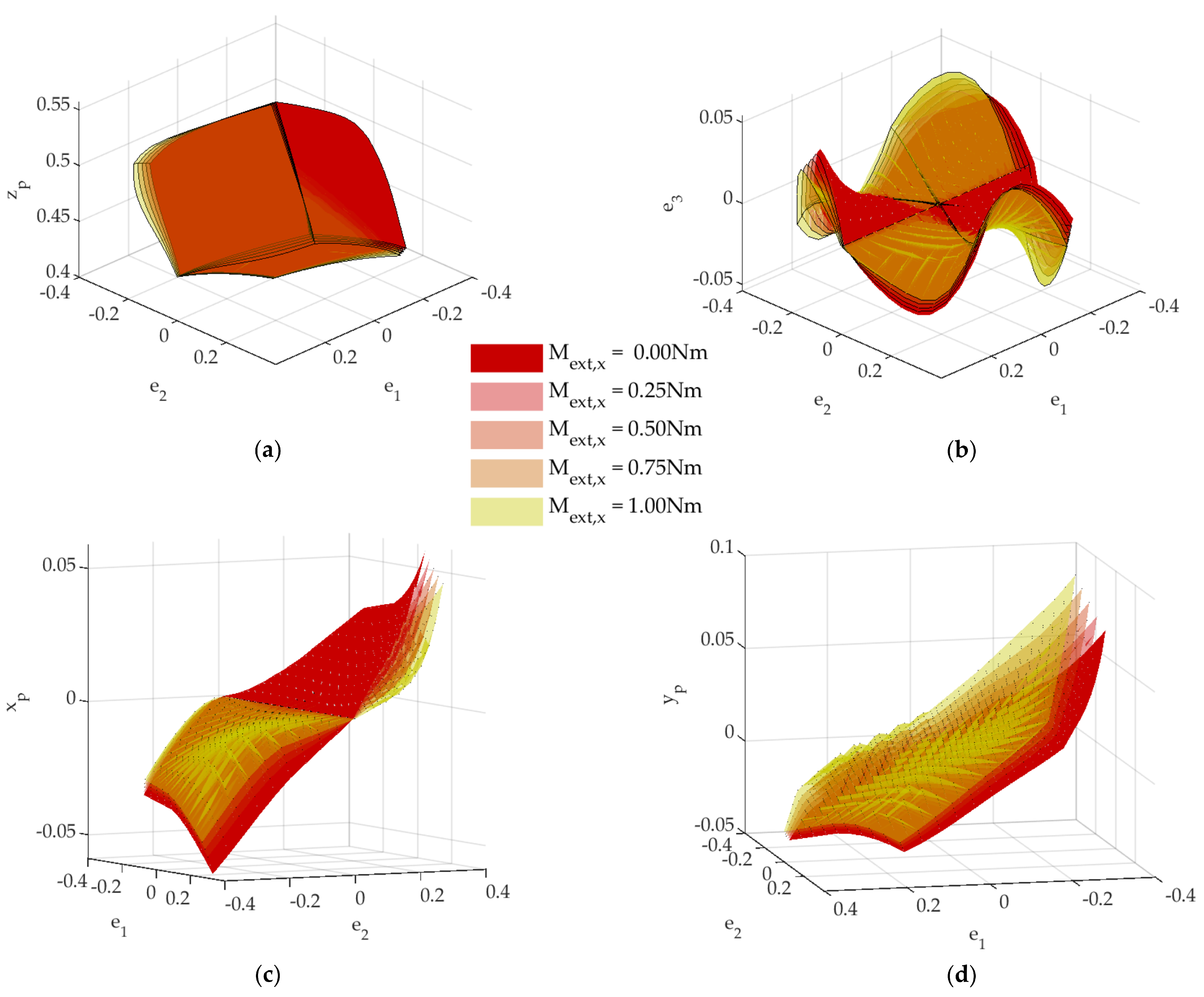
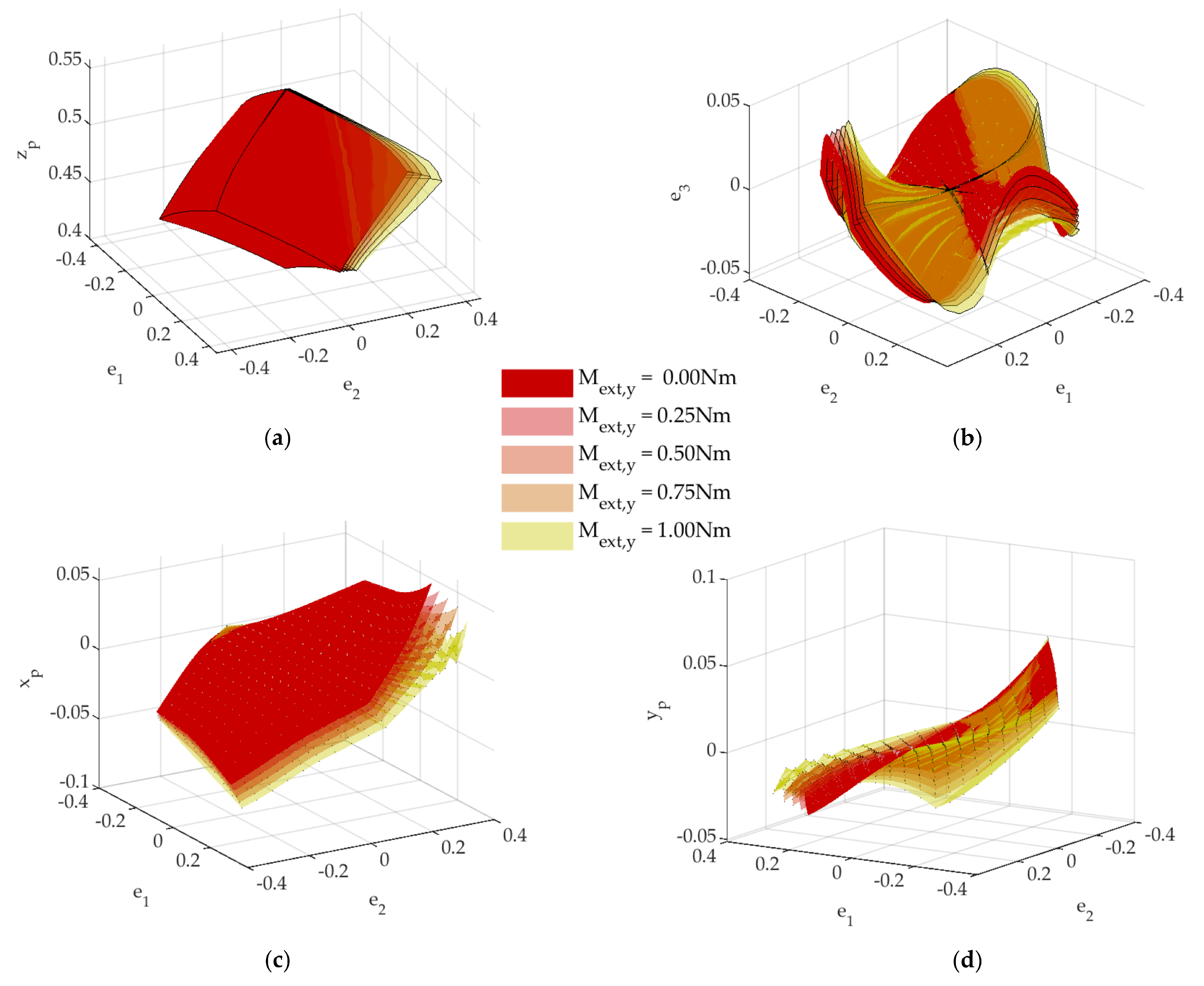
In this section we will elaborate on the above-mentioned methodology: first, to deduce the constraint equations applicable and the parasitic motions produced in the rigid-link parallel mechanism ; second, to perform the kinematic analysis of the analogous flexible parallel continuum mechanism; third, to compare and discuss the fulfillment of constraint equations with the simulated output motions of the .
3.1. Constraint Analysis of a Tripod using Euler–Rodrigues Parameters
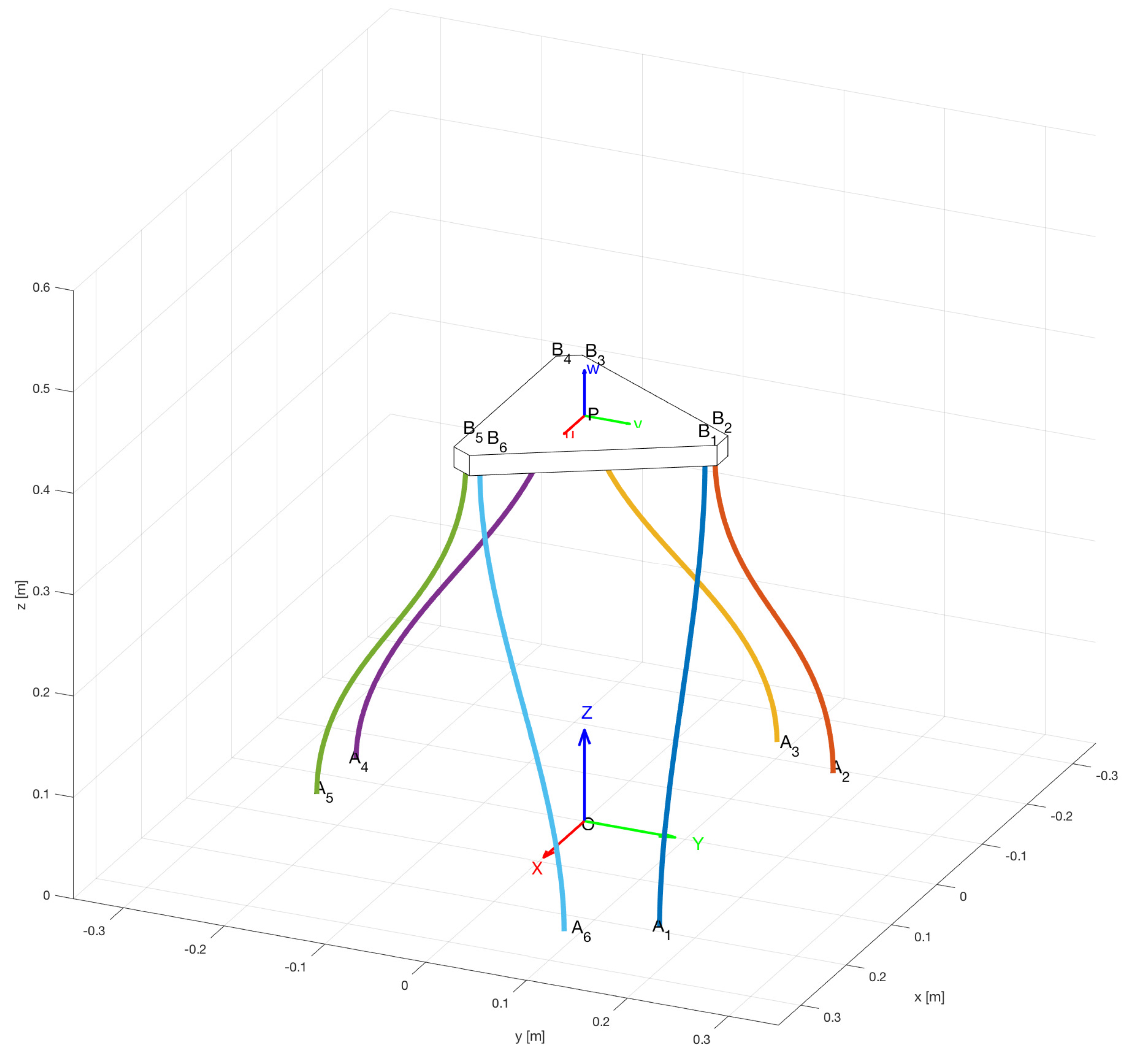
The rigid-link parallel kinematic mechanism chosen for the discussion is a tripod-like mechanism with the
morphology, as shown in
Figure 1. The mechanism is formed by a rigid end effector joined by spherical joints to rigid links of constant length
L, that are joined to vertical linear actuators through revolute joints of horizontal axes. A moving frame is attached to the end effector at reference point
P, whose position in a fixed frame is
. The orientation of the moving frame with respect to the fixed frame, i.e., orientation of the end effector, is defined either using a rotation matrix
or Euler–Rodrigues parameters (a unit quaternion
). The position vector of spherical joints’ attachment points
expressed in the end effector’s frame is
. The position vector of the actuators’ attachment point
expressed in the fixed frame attached to the base at origin
O is
. Revolute joints at points
have horizontal axis
.
Three loop-closure equations at
can be stated through the three limbs of the parallel kinematic mechanism as:
As the passive revolute joint of each limb constrains its corresponding point
to be on a vertical plane
perpendicular to
through
, which also contains points
O and
, we get the set of three constraint equations by dot-multiplying Equation (
1) by vectors
, namely:
Using Euler–Rodrigues parameters
to express the rotation matrix allows a polynomial representation of output orientation, namely:
subject to:
where the Euler–Rodrigues parameters are related to the Euler pole
and the angle rotated
in the following way:
If the symmetrical arrangement of the system shown in
Figure 1 is considered, we have an equilateral triangular end effector with a circumradius
r so that in the moving frame we get:
and revolute axes oriented in the fixed frame as:
Upon substitution of Equations (
3), (
7), and (
8) into Equation (
2), and considering Equation (
4), we get the following
constraint equations:
As a consequence, for the kinematic analysis of this tripod mechanism we can choose
as the three independent output pose parameters, with dependent parameters
determined from the
constraint equations Equation (
9). Moreover, as
is only null when there is no output rotation the
constraint equations can be expressed as:
Dependent parameters
acquire non-null values as the end effector moves; these are called
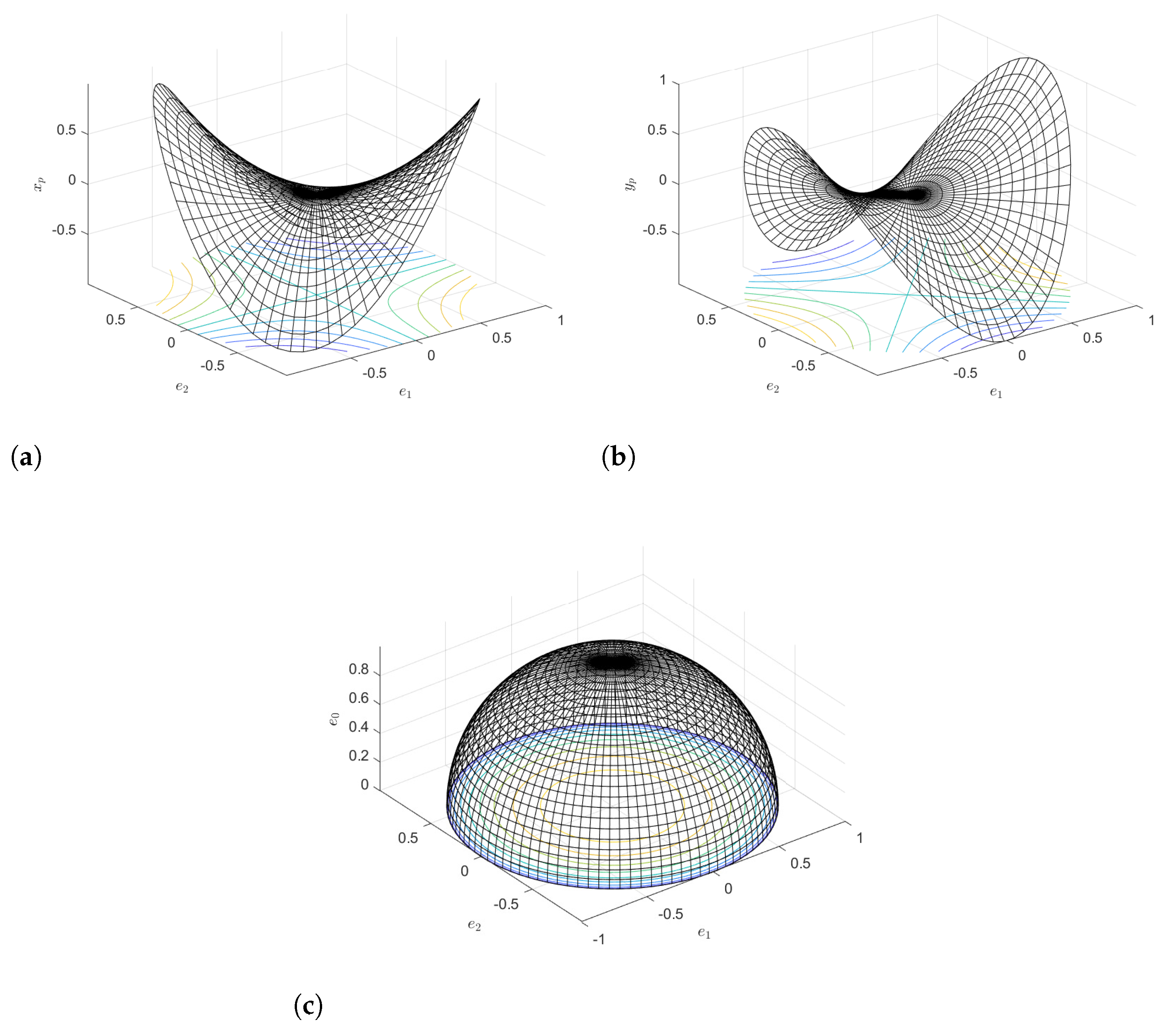
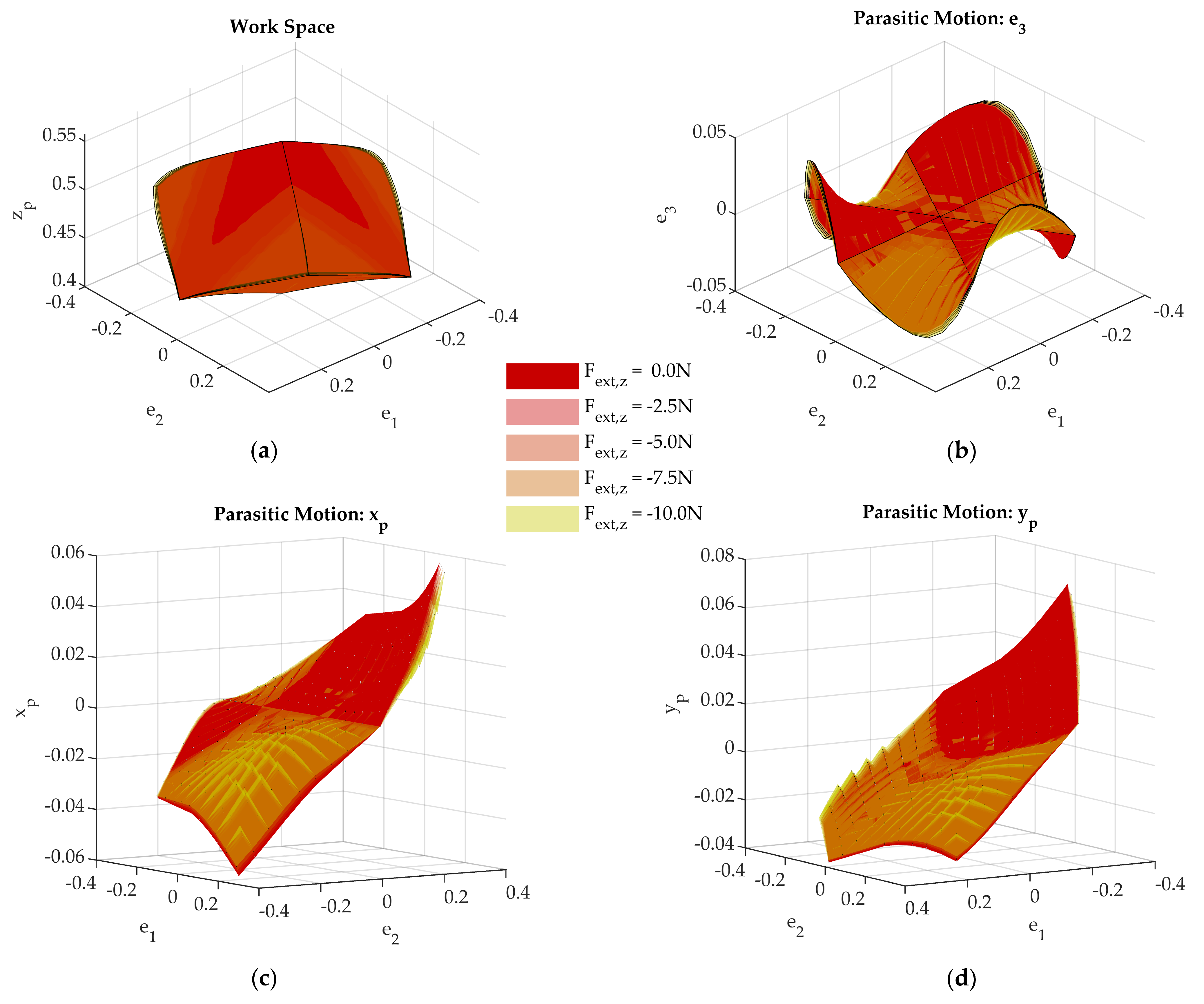
parasitic motions. We can plot the workspace of the mechanism in the space
. Moreover, as dependent parameters are expressed solely in terms of
in constraint equations Equation (
10), parasitic motions for any possible motion of the mechanism can be plotted in the space
where
as shown in
Figure 4 for
. This result of the constraint analysis is proof of its reduced mobility of three degrees of freedom. Moreover, the analysis of the effect of the three geometrical constraints justifies that the type of motion on the end effector is a
(two rotational and one translational).
The kinematic analysis of the relationship between the actuators’ input lengths
and the independent output parameters
, using the loop-closure equations (Equation (
1)), provides the solution to either the forward (FK) or the inverse (IK) position problem. First, we get rid of passive variables by finding the Euclidean norm of
in Equation (
1), namely:
where a symmetrical arrangement of actuators with
points at a circumradius
defines:
and actuators’ inputs are given by:
Finally, we introduce constraint equations from Equation (
10) into Equation (
11). The resultant system has three equations in three unknowns:
for the FK and
for the IK.
Velocity analysis is performed on the derivative of the loop-closure equations Equation (
1), namely
where
is the angular velocity of the end effector, and
is the angular velocity of the rigid connecting link
.
Dot-multiplying Equation (
14) by
, we get rid of
, obtaining a relationship between velocity inputs and velocity outputs:
and dot-multiplying Equation (
14) by
, we get the relationship between derivatives of output independent and dependent variables, i.e., the derivative of the constraint equations:
Upon assembly of Equations (
15) and (
16), we get the Jacobian equation:
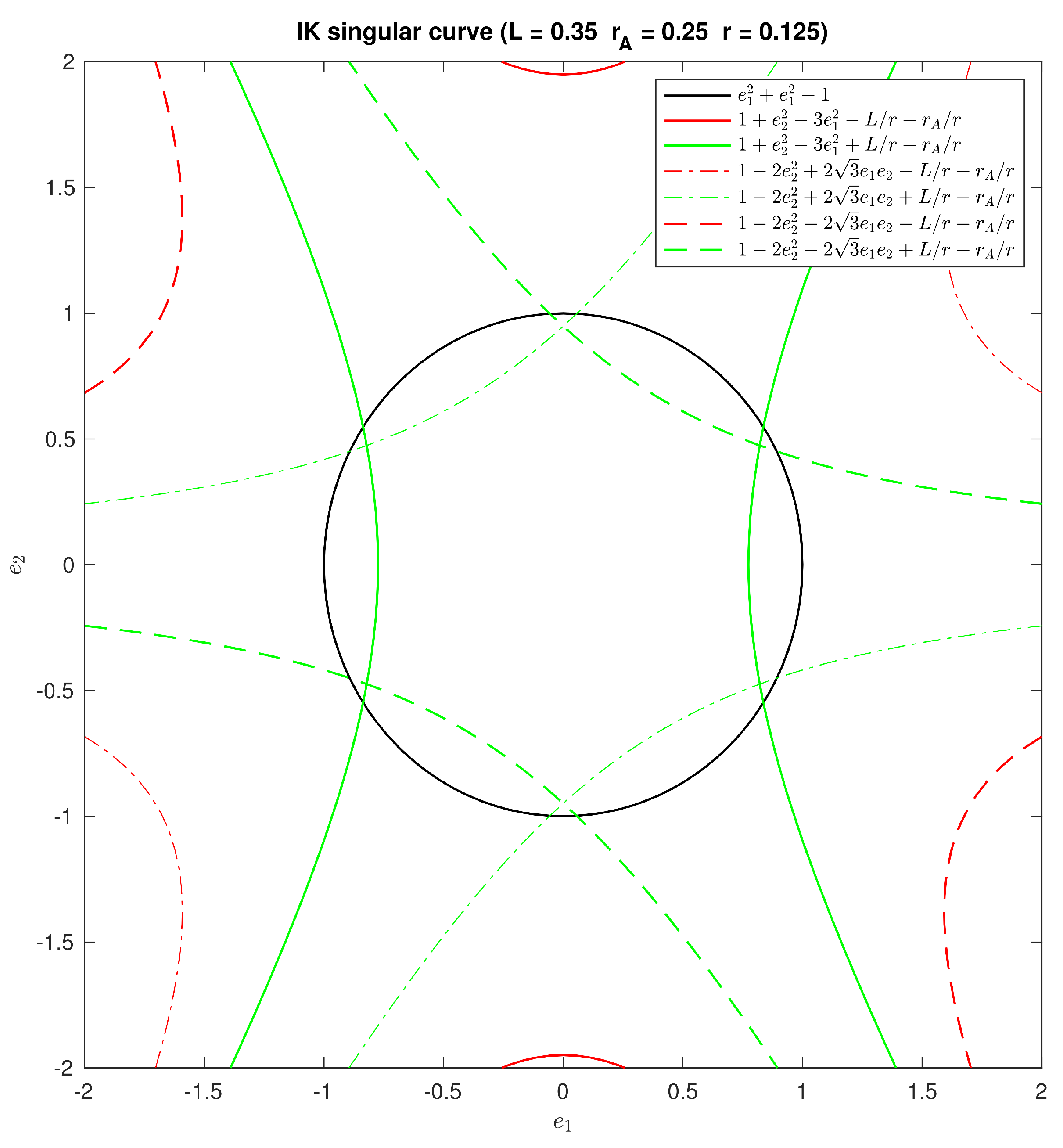
With those Jacobians, we can perform the singularity analysis to determine the limits of the position analysis. IK singularity is determined by the conditions for rank deficiency in:
which developed in terms of output variables result:
As a result, the space of parasitic motions shown in
Figure 4 will be limited by IK singularity loci (see
Figure 5 with
,
, and
).
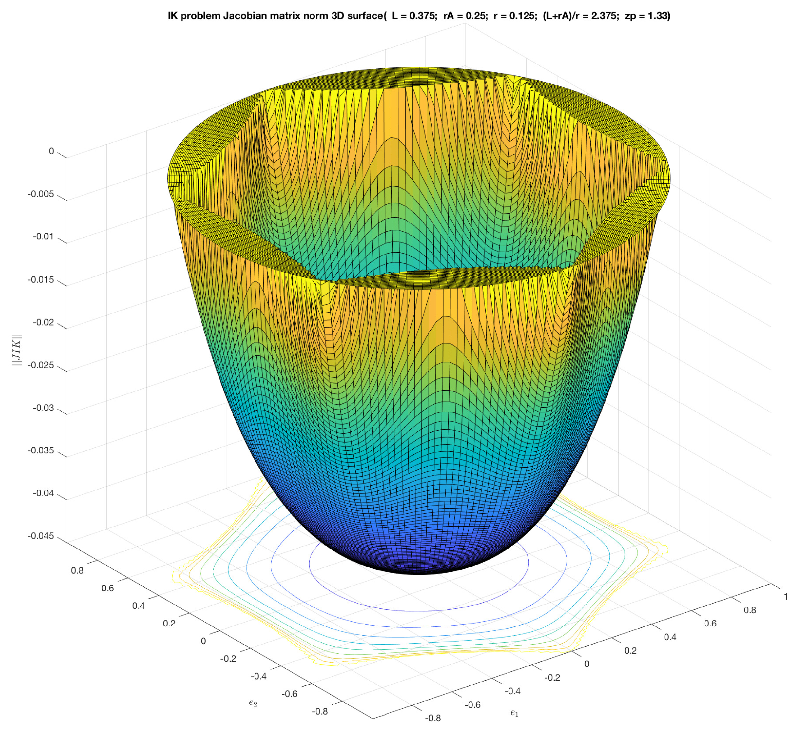
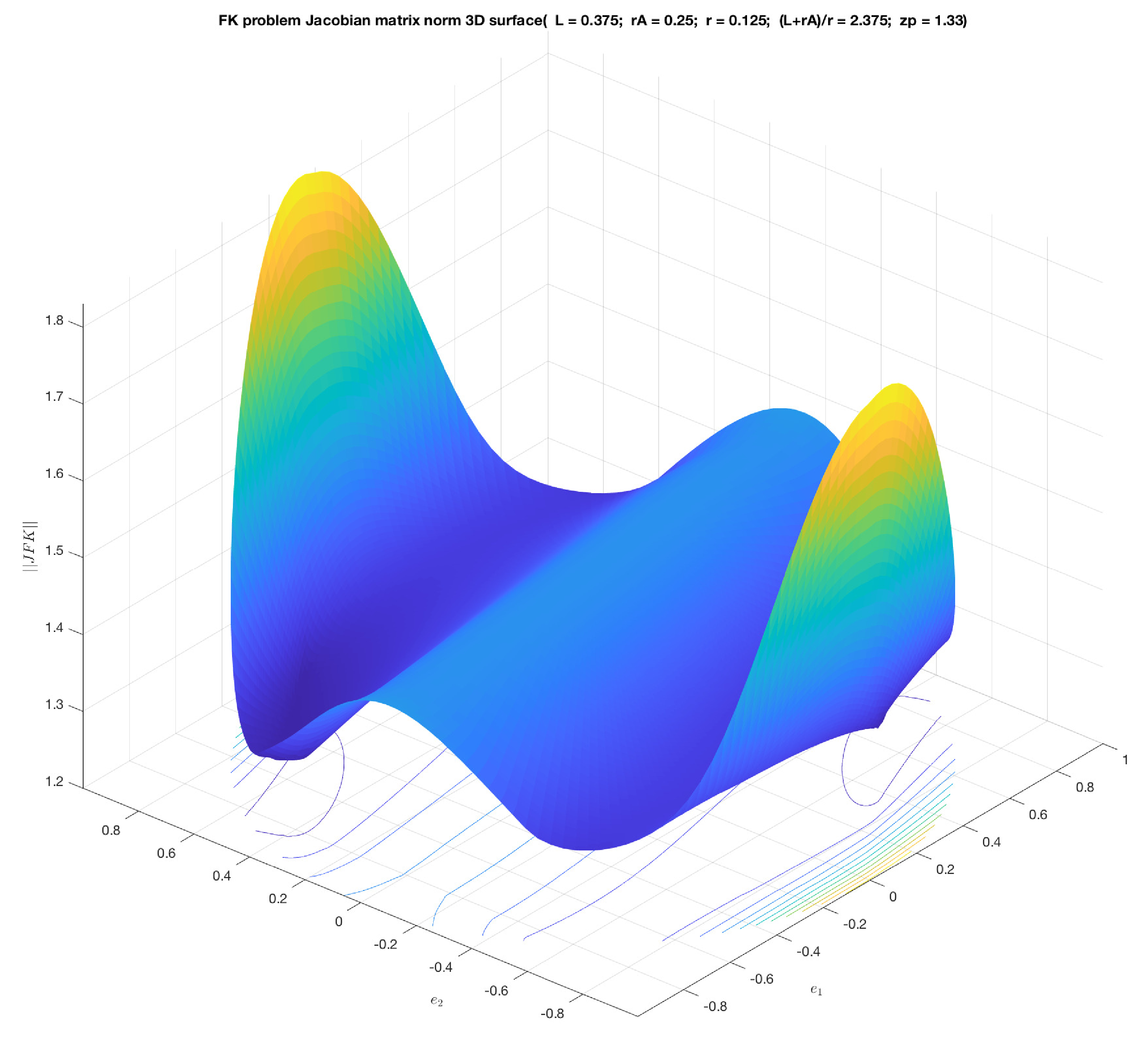
The aforementioned Jacobians can be analyzed on this workspace to obtain dexterity indices, as shown in
Figure 6 and
Figure 7.
Nevertheless, the parasitic motion functions do not change, and the mobility analysis can be fully defined with the constraint equation (Equation (
10)) and the plots in
Figure 4. These will be used in the comparison with the motion of the flexible tripod mechanism.
3.2. Forward Kinematic Analysis of a Parallel Continuum Tripod
The second step in the method is to analyze the flexible
parallel continuum tripod shown in
Figure 3 and to check the type of motion performed as inputs are introduced. As before, a moving frame is attached to the end effector at reference point
P, whose position in a fixed frame is
. The orientation of the moving frame with respect to the fixed frame, i.e., the orientation of the end effector, is defined using a rotation matrix
in terms of Euler–Rodrigues parameters (i.e., a unit quaternion
). The position vector of rod attachment point
expressed in the end effector frame is
. The position vector of rod attachment point
expressed in the fixed frame attached to the base at origin
O is
.
The forward kinematics problem consists of determining the pose of the end effector, i.e., the position vector of reference point P, , and the orientation given by the rotation matrix , when each rod i takes a certain value of its effective length and a given load is imposed.
The nonlinear large deformation of the flexible rods is analyzed with the Kirchhoff model [
12]. Each cross-section of the rod
i along the arc length
s is located with a vector pointing its centroid
and a local frame oriented with a unit quaternion
(see
Figure 8). The rods’ internal moments
are related to the rods’ curvature
along length
s, or vice-versa, with the material constitutive law given by
, where
is a stiffness matrix for bending and torsion; no extension–compression or shear effects are considered in this model to affect internal forces
.
The change of shape of the flexible rod and the equilibrium of internal forces and moments with the load along
s are related through a system of differential equations
that can be stated with the vector
of variables
and the vector of functions
:
Considering the expression of the rotation matrix that defines the orientation of each cross section along the arc length
s in terms of a unit quaternion:
and the change of the quaternion along
s with
where
everywhere because the flexible rods used in the mechanism are free of torsional effects.
We get the following system of differential equations:
As it can be observed, with no load applied along the arc length of the rod, the internal force is constant along the rod, while the evolution of , , and , can be obtained upon integration of the system of equations using, for example, the Runge–Kutta method, from to .
Hence, solving the position problem of the mechanism is started with the integration of each rod numerically by Runge–Kutta from known data values at (the position of the base tip of the rod and orientation of the base tip , and given inputs ), and guess values of , , . To reach convergence with certain security, starting from a known home pose helps to initialize the solving of the problem because those values serve as guess values to find the next solution with the new input values of actuators chosen close enough to secure convergence. The step-by-step solution will lead from that home pose to the required one.
As a result of this iteration, we get for each rod its end tip location and curvature components , , to verify the conditions imposed by the mechanism assembly and load. This is done by expressing those conditions in terms of residuals that have to be minimized following an iterative procedure ruled by a Newton scheme.
There are two main conditions that must be satisfied so that a pose of the flexible mechanism is achieved with the data introduced: first, that it can be assembled geometrically; and second, that the configuration is in static equilibrium.
Regarding the first condition, we have the coordinates of the distal end
as a function of the output pose of the end effector, namely
to be related to the coordinates of the end tip of the flexible rod
obtained from the deformation model (as explained before) and the known and fixed position
of the proximal end
of each rod:
so the following set of conditions (
) must be fulfilled:
Additionally, as distal ends are joined to the end effector through spherical joints, no moment must appear there. Moreover, no torsional effects are present anywhere on the rods due to the type of joint to the base. Bearing in mind that we can easily change from the rods’ internal moments
to the rods’ curvature
along length
s, or vice-versa, with the material constitutive law given by
, the null moment conditions at distal ends (
) to be verified are simply expressed in terms of the components of curvature in the cross-section of the distal ends as:
Static equilibrium conditions, unlike geometric ones, are stated for the whole device at the same time. This means that the end effector and all rods’ values are highly coupled in the set of equations. The end effector may be subjected to external load
at
P and
, and to reaction forces and moments at the attachment to rods due to their deformation, namely internal forces
and moments
at
. So, the following static equilibrium can be stated, taking moments about
O:
The problem to be solved is made up of the geometric conditions on the position of distal ends (Equation (
27)), i.e., 3 scalar equations at each rod for a total of 18; the geometric conditions on the attachment of distal ends to end effector (Equation (
28)), i.e., 2 equations for each rod, 12 in total; and the static equilibrium conditions on the end effector (Equation (
29)), i.e., 6 more, to make a total of 36 conditions.
The unknowns are due to the state variables of each rod necessary to integrate the six subsystems of differential equations for each rod, i.e., the unknowns in and (alternatively ) being five because there is no torsion; plus the six unknowns that define the end effector pose and , a total of thirty-six unknowns.
As the orientation of the end effector with respect to the fixed frame is more effectively expressed with a unit quaternion
, the corresponding rotation matrix
has four components to be used as unknowns instead of three, making a total of thirty-seven unknowns and another condition has to be added, namely the unity condition of the quaternion:
Hence resulting in a problem of 37 unknowns in 37 conditions.
Due to the integration involved in each rod, the solution must be approached as a boundary value problem: guess values of unknowns at the lower end for each rod (namely , ) and the output pose ( and ) are introduced, and a shooting method iterates until residuals of the boundary conditions are below a tolerance.
The chosen order of those residuals will provide an adequate distribution of terms to lower the computational cost. First, the geometric constraints for the rod
, i.e., Equations (
27) and (
28), then the same geometric constraints but for the rod
, and so on until
. The last elements of the residue vector are formed by the equations of equilibrium (Equation (
29)), and the normalization condition of the end effector quaternion (Equation (
30)), namely
The Newton method used in the shooting method requires the evaluation of a Jacobian of the residue vector function with respect to the variables of the problem, i.e., the guess values
,
and output pose
and
, in order to update the guess values accordingly. A special order for the guess values is also considered to generate a Jacobian sparse matrix. They are grouped so that the guess values associated with a rod are together:
The Jacobian is then obtained as:
The Jacobian related to the forward kinematic problem is a sparse matrix
of the form
Each sub-matrix is calculated considering the residue associated with the geometric conditions for the rod i and the kinematic variables used as guess values for the rod i. Similarly, matrix is defined considering the residue associated with the static conditions that affect the whole mechanism and the kinematic variables used as guess values for rod i. Matrix is calculated considering the residue associated with the geometric conditions for the rod i and the coordinates of P are used as guess values. Matrix is calculated considering the residue associated with the geometric conditions for the rod i and the kinematic variables used as guess values for the orientation of the end effector. Finally, matrix is defined considering the residue associated with the static conditions and the output position of P of the end effector; while matrix is defined considering the residue associated to the quaternion normalization condition and the orientation of the end effector.
After each iteration
j, guess values are updated with:
and the process starts again until
is below a given tolerance.
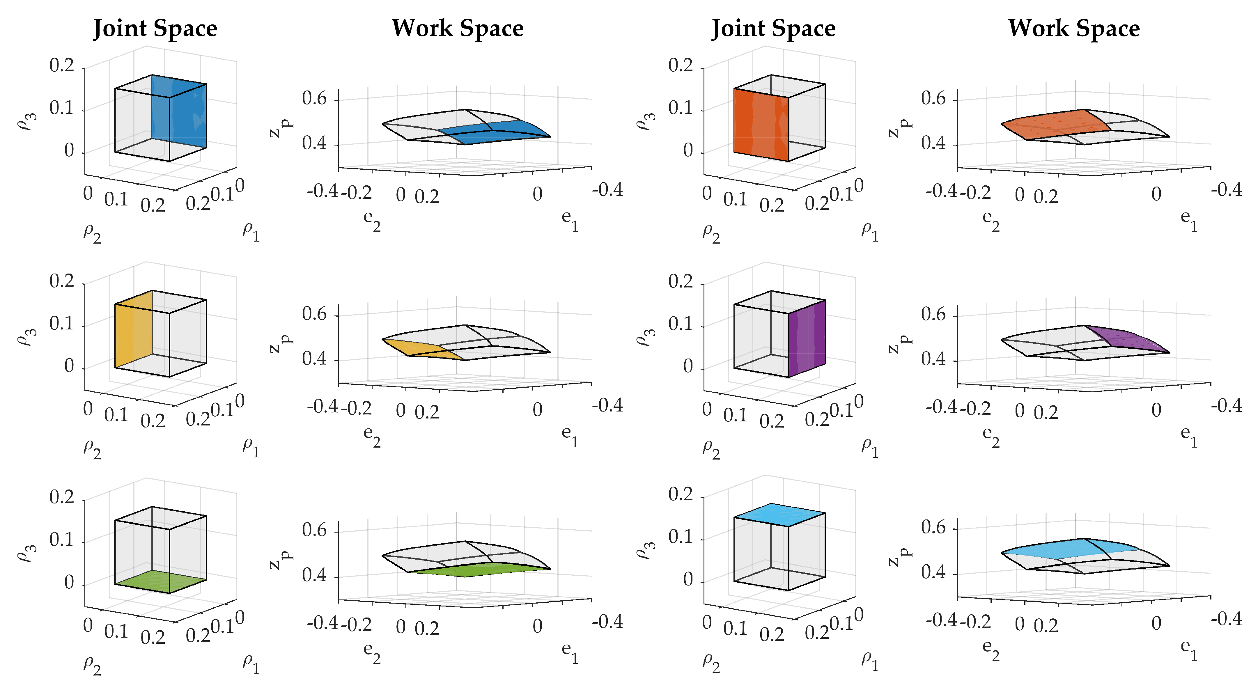
Starting from a home pose where the end effector is placed horizontally at a certain height, introducing a variation in inputs following the distribution on the jointspace, as shown in
Figure 9, and solving the FK position problem using the procedure above, we get the set of output poses represented in the workspace
.
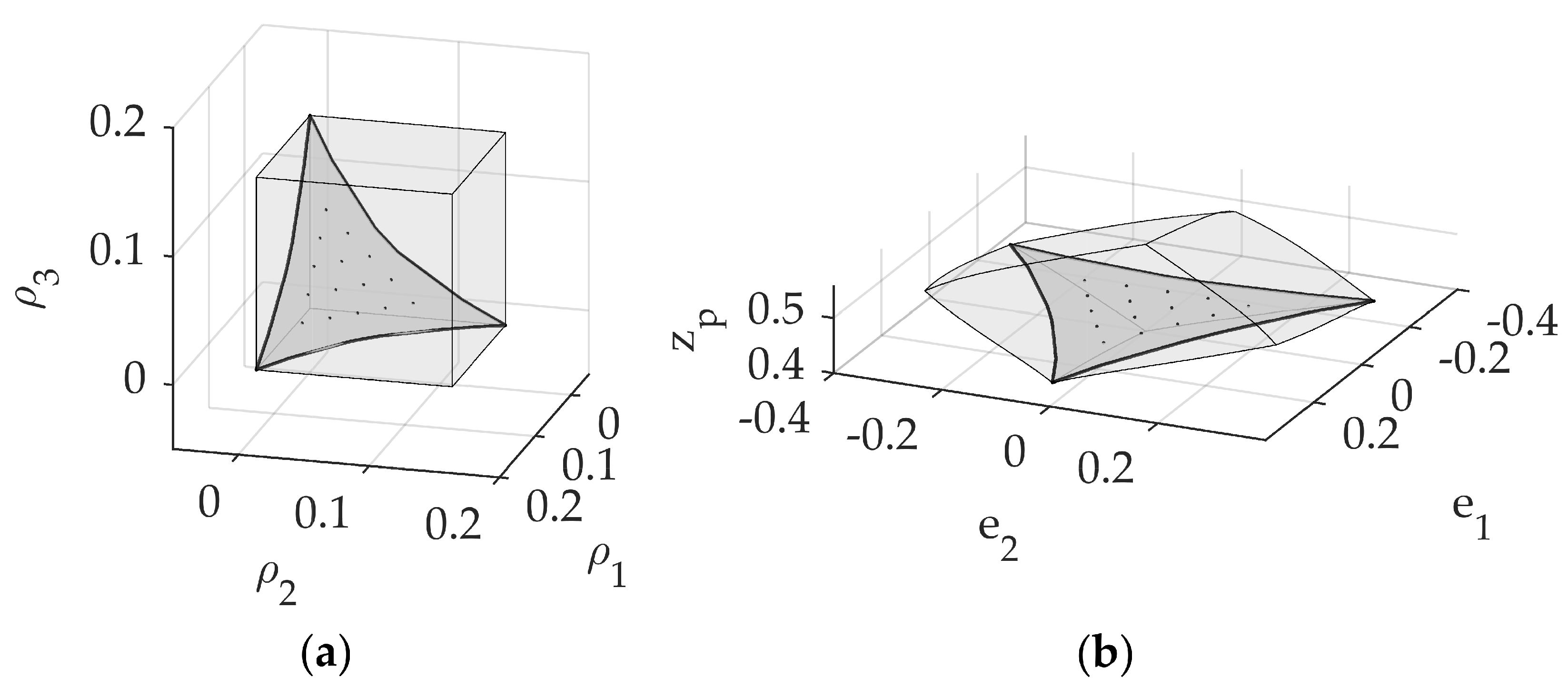
As the geometrical arrangement of flexible rods and actuators produces a workspace that is independent of
as in the
, it is convenient to get the jointspace subset that produces the output poses on a horizontal plane, as shown in
Figure 10.
From the solutions found in the above-mentioned analysis, it is possible to do a comparison with those obtained for the rigid link parallel mechanism analyzed in the first part of this work. In the next section some of these preliminary results will be discussed.

