1. Introduction
As an important part of the future development of rail transit, maglev train has the advantages of low pollution, low noise, small turning radius, strong climbing ability, low maintenance cost, and energy saving. Maglev train can be divided into two types in principle: One is electromagnetic suspension (EMS) maglev train; the other is electrodynamic suspension (EDS) suspension train [
1]. Compared with EDS type suspension train, the technology of EMS type is more mature. At present, EMS transportation lines that are placed into operation include the hilly line in eastern Japan and the maglev line in Changsha, China [
2].
The key technology of EMS maglev train is suspension control technology. The control problem in the vertical direction of the suspension system can be simplified into the suspension control problem of a single electromagnet [
3]. In the maglev system, the attraction of the electromagnet is inversely proportional to the square of the track gap and directly proportional to the square of the coil current of the electromagnet. It can be seen that the maglev system is a strong nonlinear system [
4]. At present, there are many researches on the levitation control strategy of maglev train, including traditional control, modern control, and various intelligent control algorithms. However, to date, the method of large-scale application is still the design of PID controller based on linearized maglev model. However, with the passage of time, its shortcomings become increasingly clear. PID controller is sensitive to system parameters [
5]. During the operation of maglev train, the suspension gap between track and electromagnet should be maintained at about 8 mm. The deterioration of control performance caused by system parameter drift may cause serious consequences, such as train track resonance, train bumping, and even rail scraping. How to ensure that the maglev train can maintain the levitation performance to the greatest extent under the complex working conditions, such as noise and load, is one of the core problems that limit the engineering application of maglev train.
Sliding mode control is a type of nonlinear control in essence. It has the characteristics of simple physical implementation, fast response, and strong robustness. It can overcome the influence of system uncertainty. The application of sliding mode control to maglev system can effectively solve the problem of poor control effect caused by the unmodeled part of the system and the nonlinearity of the system model. Chen proposed a robust nonsingular terminal sliding mode control (RNTSMC) system [
6]. Compared with the traditional linear sliding mode control (SMC), the terminal sliding mode control (TSMC) with nonlinear terminal sliding mode surface has faster finite time convergence speed and higher control accuracy. Based on the linear model of magnetic levitation, Zhou and Long designed the sliding mode controller and successfully implemented the algorithm with analog circuit [
7]. Molero combined two nonlinear control tools: Exact linearization and sliding mode control, and verified the good performance of the system through MATLAB simulation [
8]. However, sliding mode control also has its own shortcomings. For example, the traditional sliding mode control is easy to produce steady-state error. In addition, due to the discontinuity of the controller, it is easy to cause high-frequency vibration of the controller input, resulting in the phenomenon of system “chattering”.
Han, with the aim of the widespread problem of anti-interference in the control field [
9], weakened the role of the system model from the engineering practice, and proposed an active disturbance rejection controller according to the idea that “all control problems are anti-interference problems in essence”, which improved the robustness of the controller. He [
10], Zhou [
11] applied active disturbance rejection control (ADRC) to the magnetic levitation control system, which solved the problem of poor control performance when the system parameters changed, and improved the control effect of the system. However, there are a large number of parameters to be set for the ADRC, and the parameter setting process is also complex. To simplify the controller structure and reduce the number of parameters to be set, Gao proposed a linear ADRC method, and creatively proposed a bandwidth parameterized parameter setting method [
12,
13], which simplifies the controller parameters to be set to three, greatly improving the engineering application value of the ADRC method. At the same time, the stability and convergence of the linear ADRC are also proved. Zhang [
14] et al. successfully applied the linear active disturbance rejection control to the magnetic levitation field, and proved that the linear active disturbance rejection control is superior to the PID controller in terms of fast response and external disturbance suppression. Based on the super-twisting algorithm (STA) and the nonsingular terminal sliding mode (NTSM) theory, Qu [
15] proposes a new active disturbance rejection continuous second-order sliding mode guidance law for Missile, in which the chattering problem inherent in sliding mode control can be completely eliminated without sacrificing the control accuracy. At the same time, the non-linear extended state observer (ESO) with differential tracker is used to estimate the total disturbance in real time, and feedforward compensation is carried out in the second-order sliding mode guidance law, in order that the system has strong anti-interference and anti-noise ability. At present, the ADRC method based on linear extended observer has been successfully applied in many industrial fields, and the related theory of linear active disturbance rejection control (LADRC) has been supplemented and enriched.
The main work of this paper is as follows: A new sliding mode control method for maglev system based on extended state observer is proposed. By applying the extended state observer (ESO) of linear active disturbance rejection method, combined with sliding mode control, the control performance and adaptability to external disturbances are improved.
The main contributions of this paper are:
The traditional sliding mode controller is designed for the suspension system;
Combining linear state observer with sliding mode control, a sliding mode control method for maglev system based on extended state observer is designed;
The designed controller is numerically simulated, and the effectiveness and superiority of the new algorithm are verified by comparing the PID control, the sliding mode control, and the sliding mode control strategy based on extended state observer.
First, we need to model the suspension system and simplify the model through some assumptions, such as considering the fact that the orbit is an absolute rigid body, in order to facilitate the subsequent design of controller.
2. Mechanism Modeling and Analysis of Suspension System
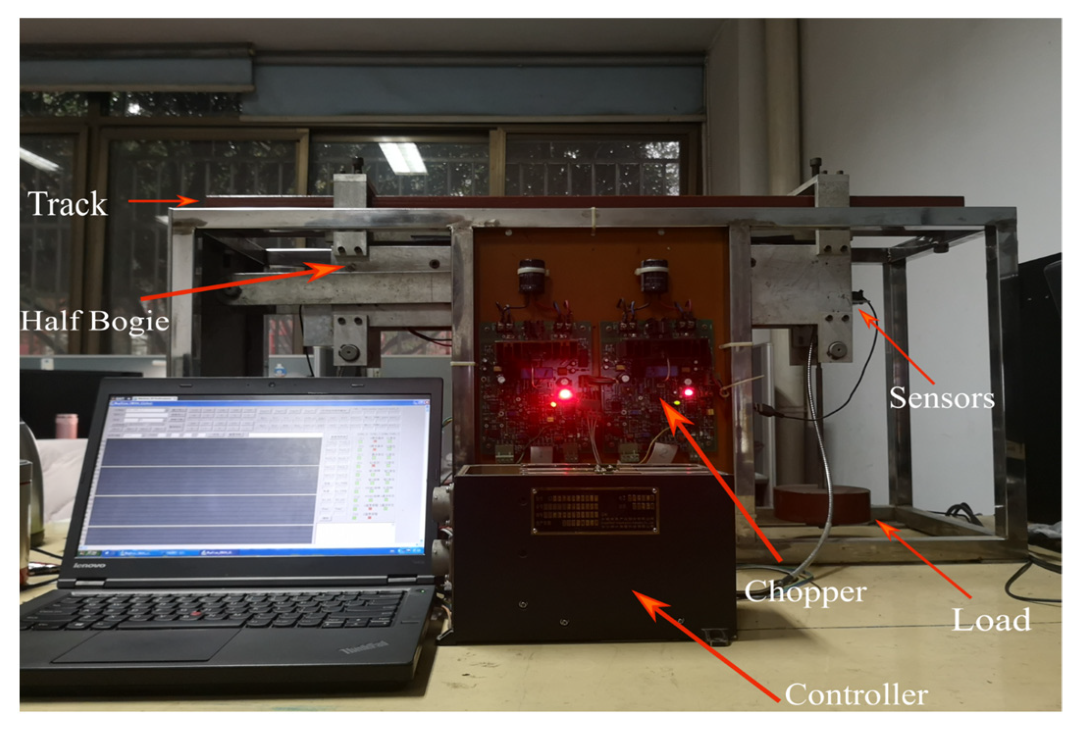
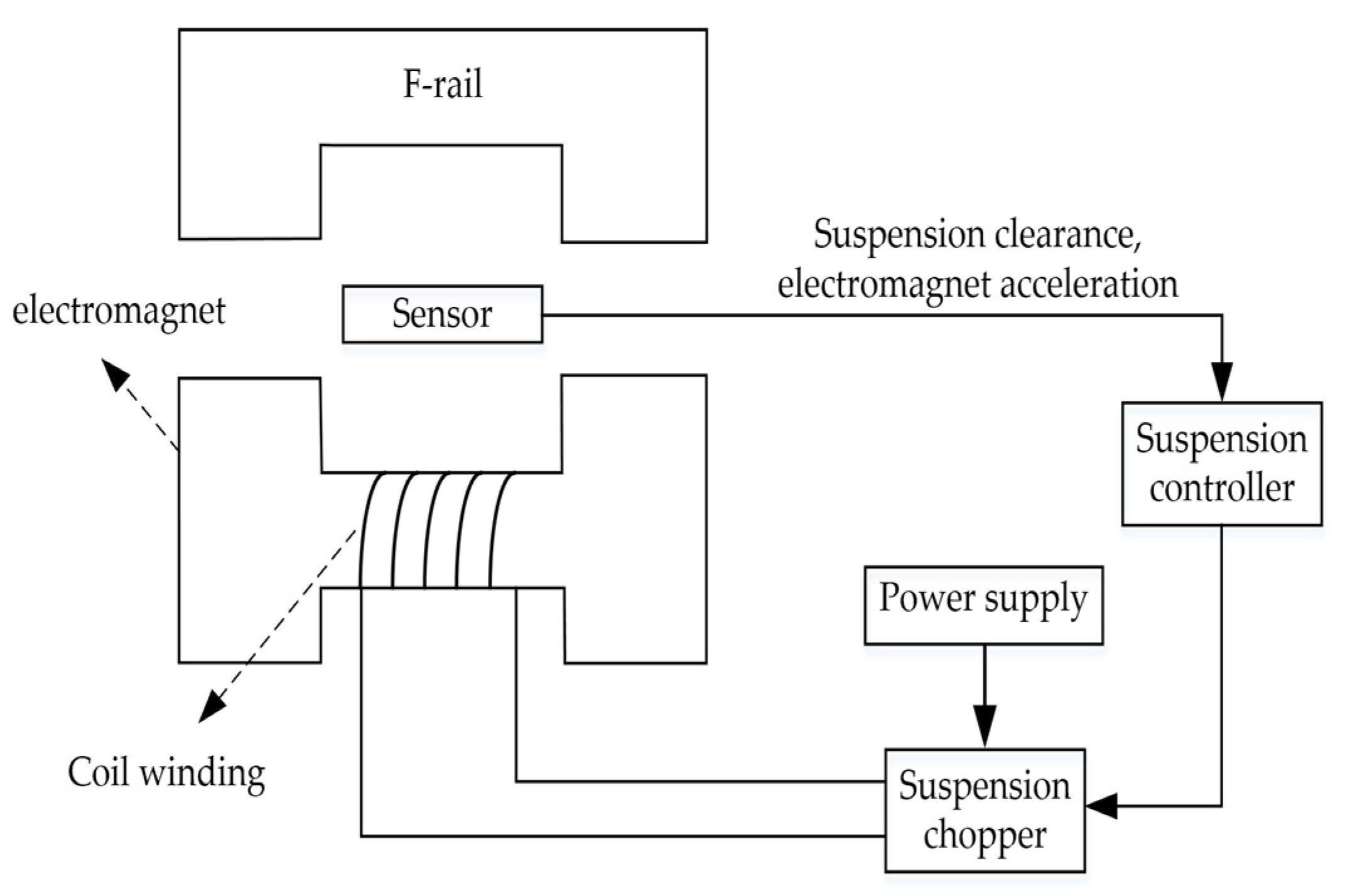
The suspension control system of medium and low speed maglev train is mainly composed of five parts, including power supply, suspension controller, gap and acceleration sensor, chopper, and electromagnet. To facilitate the study of the levitation control algorithm in the laboratory, the equally scaled down maglev system platform is adopted. The specific hardware system is shown in
Figure 1. The platform is composed of track, half bogie, sensors, chopper, load, and controller. The suspension control system structure is shown in
Figure 2.
According to a large number of theoretical research and practical engineering experience, when studying the levitation control of maglev train, it is general to analyze the control process of a single electromagnet in the levitation system of maglev train [
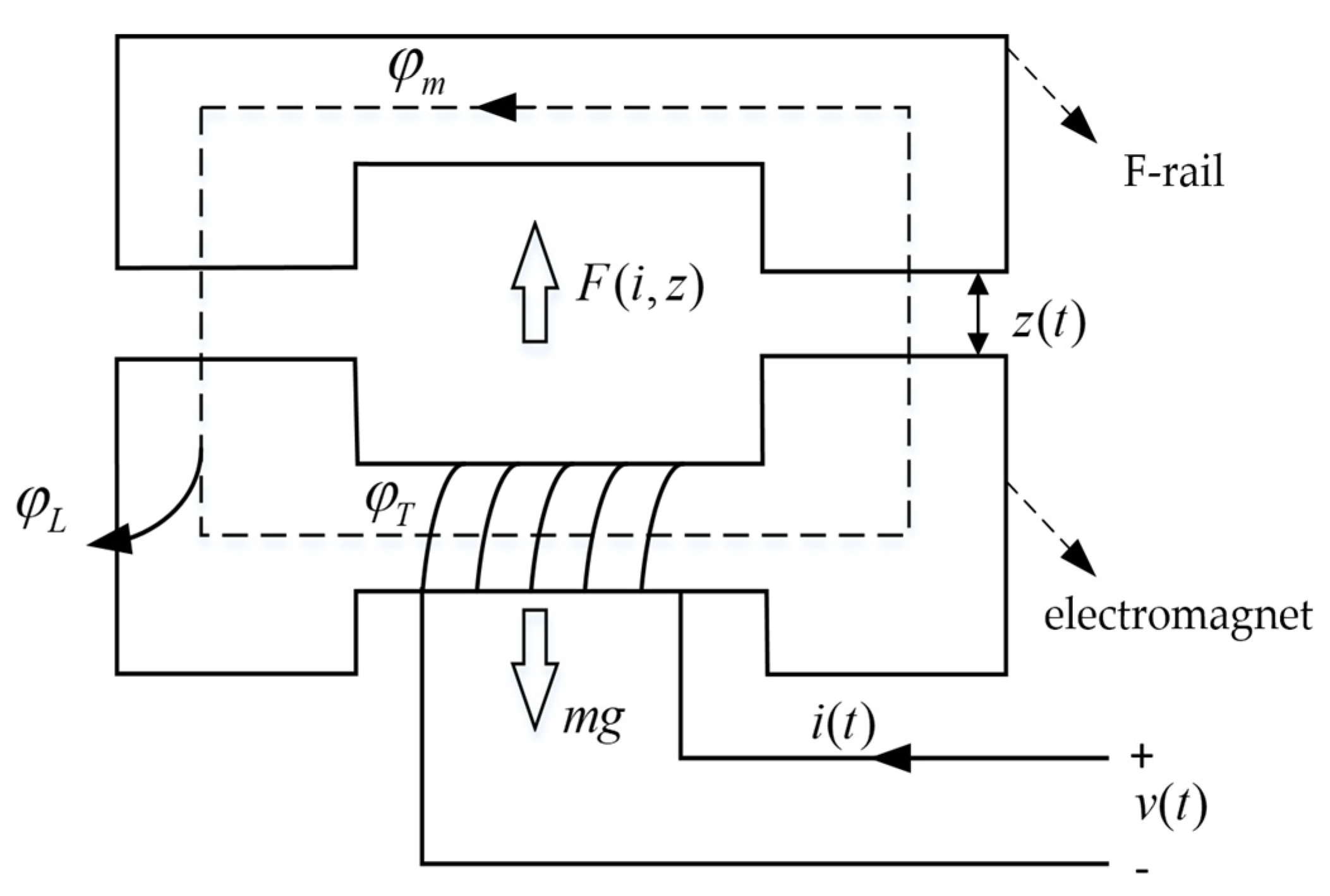
16]. The single electromagnet levitation control refers to the control of the vertical levitation direction of the train, namely, the gap between the levitation magnet and the track is stabilized at the desired value by applying control. The structure diagram of single iron suspension system is shown in
Figure 3. The definitions of variables in the diagram are shown in
Table 1 as follows:
To facilitate modeling and subsequent processing of the model, the following assumptions are made according to the actual engineering and research conditions [
17]:
The rail is directly opposite to the magnet, and there is no pitch angle. The leakage flux of the winding is ignored (), namely, the air gap flux is approximately equal to the main magnetic pole flux.
It is considered that the magnetic permeability in the magnet core and guide rail is infinite and the magnetic potential falls evenly on the air gap .
The magnetic saturation characteristics of track and iron core materials are not considered, namely, the B-H diagram is linear.
The orbit is regarded as an absolute rigid body without elastic vibration and dynamic deformation.
The mass of the whole system is uniformly distributed, and the center of mass of the module coincides with the assembly center.
2.1. Mathematical Model of Single Electromagnet Suspension System
According to ampere loop theorem:
Therefore, the relationship between air gap flux density
and current
and suspension gap
can be obtained as follows:
where
is the vacuum permeability, and the magnetic flux at the suspension air gap can be obtained from Formula (1):
According to the principle of electromagnetic induction, the inductance of the winding is:
Then, the empirical formula of electromagnetic force
at time
is [
18]:
From Equation (5), it can be seen that the electromagnetic attraction between magnetic rails has a nonlinear inverse square relationship with the suspension gap and winding current, which also shows the nonlinear nature of the suspension system itself. This nonlinear relationship increases the difficulty of controller design.
The voltage and current equation in the electromagnet winding circuit is:
The dynamic equation of the electromagnet in the vertical direction can be expressed as:
where
is the disturbance of external force. Let
, to sum up, the dynamic model of the single point suspension system in the direction of vertical degrees of freedom is:
By defining the state variables of the system,
,
and
represent the suspension gap, the vertical speed of the electromagnet, and the current of the coil winding, respectively, the state space model of the nonlinear system of the maglev train can be obtained as follows:
2.2. Linearization of Suspension System Model
To study the stability of the suspension system in the open-loop state, and to use the mature linear theory to design a simple and effective suspension controller, it is necessary to linearize the nonlinear suspension system. At the suspension balance point
, when the suspension system is in a stable state,
,
, thus the electromagnetic force, voltage, and current at the balance point can be obtained as:
Expand Equation (5) by Taylor series at equilibrium point
:
By overlooking the higher-order term
of Taylor expansion in the above formula, the linearized form near the equilibrium point is obtained:
Then, overlook the interference term, and bring Equations (10) and (12) into Equation (8) to obtain:
The winding voltage equation, i.e., Equation (6), is also expanded by Taylor formula to obtain:
Then, the linearized expression of the dynamic model of the maglev system shown in Equation (8) is:
Taking
as the state variable, the linearized system equation is:
Let
and
be the system current stiffness coefficient and displacement stiffness coefficient, respectively, which are:
Furthermore, the state space equation of the single iron linear model can be obtained:
According to the state space equation, i.e., Equation (18), the open-loop block diagram model of the suspension system can be drawn, as shown in
Figure 4:
2.3. Control Characteristic Analysis of Suspension System
2.3.1. Stability
The characteristic equation of the system can be obtained from Equation (18):
It is clear that the coefficient of the first-order term of the characteristic equation is 0, and the coefficient of the constant term is negative, indicating that the single point suspension system is a third-order unstable system. The Routh criteria are listed in
Table 2.
Due to , there is a negative number in the first column of the Routh criterion table, and a sign change occurs. Therefore, through the Routh criterion table, we can also draw the conclusion that the open-loop system is unstable. The controller must be designed to make the closed-loop system stable.
2.3.2. Controllability and Observability
According to the state space equation of the linear model, namely Formula (18), the controllability matrix of the system is listed as:
In addition, the observability matrix of the system is:
Since and are full ranks, the system is completely controllable and completely observable.
2.4. Current Loop Design
For single iron suspension control, the controlled system is a third-order unstable system after linearization. The early control methods used bipolar lead or state feedback control. The common feature of these methods is that to improve the suspension effect, multiple parameters often need to be adjusted at the same time, and the corresponding relationship between a single parameter and the suspension effect is not clear. To overcome this shortcoming, it is necessary to introduce a current loop to decompose the third-order suspension control system into a first-order current loop subsystem and a second-order suspension control subsystem, which can be debugged independently, thus greatly reducing the debugging difficulty of the suspension control system. The control objective of the current loop is that the current of the electromagnet can track the control voltage at the fastest speed and limit the noise within the allowable range [
19].
For the convenience of analysis, Equation (6) is rewritten into the form of equivalent resistance and equivalent inductance, as follows:
where
,
. For the convenience of analysis, when the suspension system is near the rated gap, it can be considered that
is the rated gap,
is 0, and the small changes of
and
are regarded as internal disturbances. At this time, the equivalent resistance and equivalent inductance of the electromagnet are simplified as:
Therefore, the system transfer function with voltage as input and current as output is:
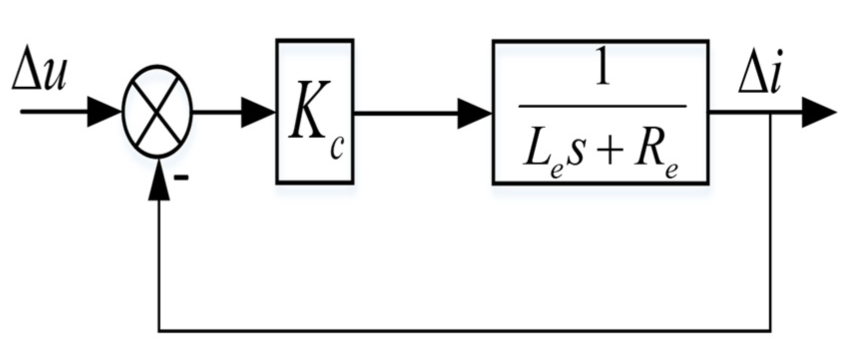
The proportional controller is adopted for the current, and the closed-loop system is called the current loop, as shown in
Figure 5. By introducing negative feedback and proportional controller, the system frequency band is expanded, and the current will track the control voltage at a faster speed. Therefore, the bandwidth
can be used as the design index of the current loop.
At this time, the transfer function of the system is:
When
, it can be approximated as
. At this time, the relationship between the system cut-off frequency
and the current proportional coefficient
is:
By building the current loop, the system model can be further simplified, and the third-order model of the suspension system can be reduced to the second-order model, which facilitates the design of the gap controller. Therefore, the subsequent controllers adopt the form that the outer loop is the gap controller and the inner loop is the current controller.
3. Design of Traditional Sliding Mode Controller
3.1. Sliding Mode Control Principle
There are many uncertain factors in the actual working environment of the maglev system, such as friction, load, and other external interference, which seriously affect its control accuracy, and may even affect the stability of the system. Sliding mode control has good flexibility, simple design method, and strong robustness, and is widely used in the field of nonlinear control.
Define any nonlinear system as
, where
,
,
. The sliding mode surface is defined as
, where
and switching surface
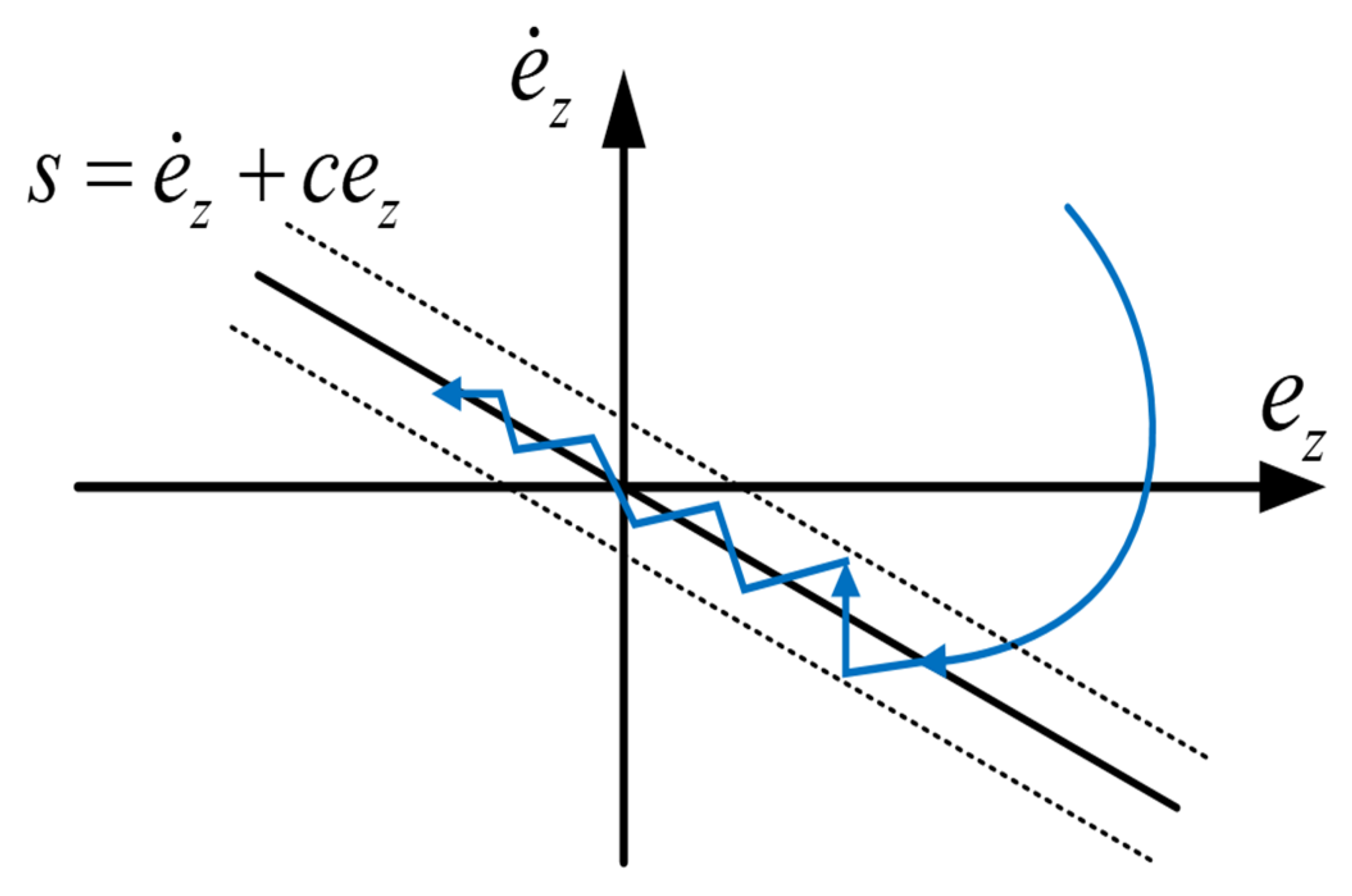
divide the state space into two parts greater than zero and less than zero. As shown in
Figure 6, the state motion process of the sliding mode control system is divided into two parts: The state point approaches the sliding mode surface and the state point moves on the sliding mode surface. The reaching law refers to the process that the system approaches the sliding mode surface from the distant initial state to the sliding mode surface.
3.2. Design of Sliding Mode Controller
According to the design of the current loop in
Section 2, when
, the time constant of the current loop is very small, the voltage current transfer function can be approximately 1, the system is reduced from third order to second order, and Equation (9) can be simplified as:
where
is the gap between the electromagnet and the rail,
is the speed of the electromagnet, and the vertical downward direction is the positive direction. Let
, i.e.,
be the upper boundary of interference
.
To design the sliding mode controller, the error
is first defined:
where
is the expected value of
. Therefore:
Since the final control goal is to achieve the desired gap value from the initial gap value, and the derivative of the electromagnet speed will be reduced to 0, namely,
and
. Thus, the design of slide mode surface is:
When the system reaches the sliding mode, i.e.,
:
By solving this first-order homogeneous differential equation, we can obtain:
Namely, when , the error converges to zero exponentially, and the convergence rate depends on the value of . Therefore, the convergence of error function indicates the convergence of tracking error and velocity tracking error . By choosing the appropriate value of , the system can quickly converge to the desired position.
Define the Lyapunov function as follows:
Let
, then Equation (33) can be further written as:
According to Equation (30) and condition
, we can get:
Therefore, the final control law is:
However, the ideal sliding mode control does not exist. In practice, the sliding mode motion will slightly deviate from the expected trajectory due to the influence of time delay, dead zone, and other reasons, thus the state of real system will traverse back and forth on the expected trajectory, resulting in buffeting, as shown in
Figure 7 below. Buffeting is harmful to many systems, especially those requiring high accuracy. It will not only affect the accuracy of system control, increase the system cost, but also destroy the stability of the system.
According to the approach law arrival strategy proposed by Gao Zhiqiang et al., the following control laws are designed:
where
is the saturation function, and its expression is:
By choosing the appropriate saturation function width
, the buffeting of the system can be reduced on the premise of approximately replacing the symbolic function
. At the same time, the exponential reaching term
is added to ensure that
can quickly approach the sliding surface when it is far away from the sliding surface. At this time, the control law of the system is:
3.3. Stability Analysis of Sliding Mode Control
It can be seen from the above description that
can approximately replace
,
, thus we can get:
Take
, then
, and:
The solution of Equation (41) is:
Since
, and
, then:
Due to , converges to zero exponentially, thus and converge to zero exponentially. The convergence rate depends on the value of in the control law.
3.4. Simulation Analysis of Sliding Mode Control
A simulation model is built in Simulink of MATLAB for simulation experiments to verify its control performance. According to the relevant parameters of the actual system, the simulation parameters are set as follows:
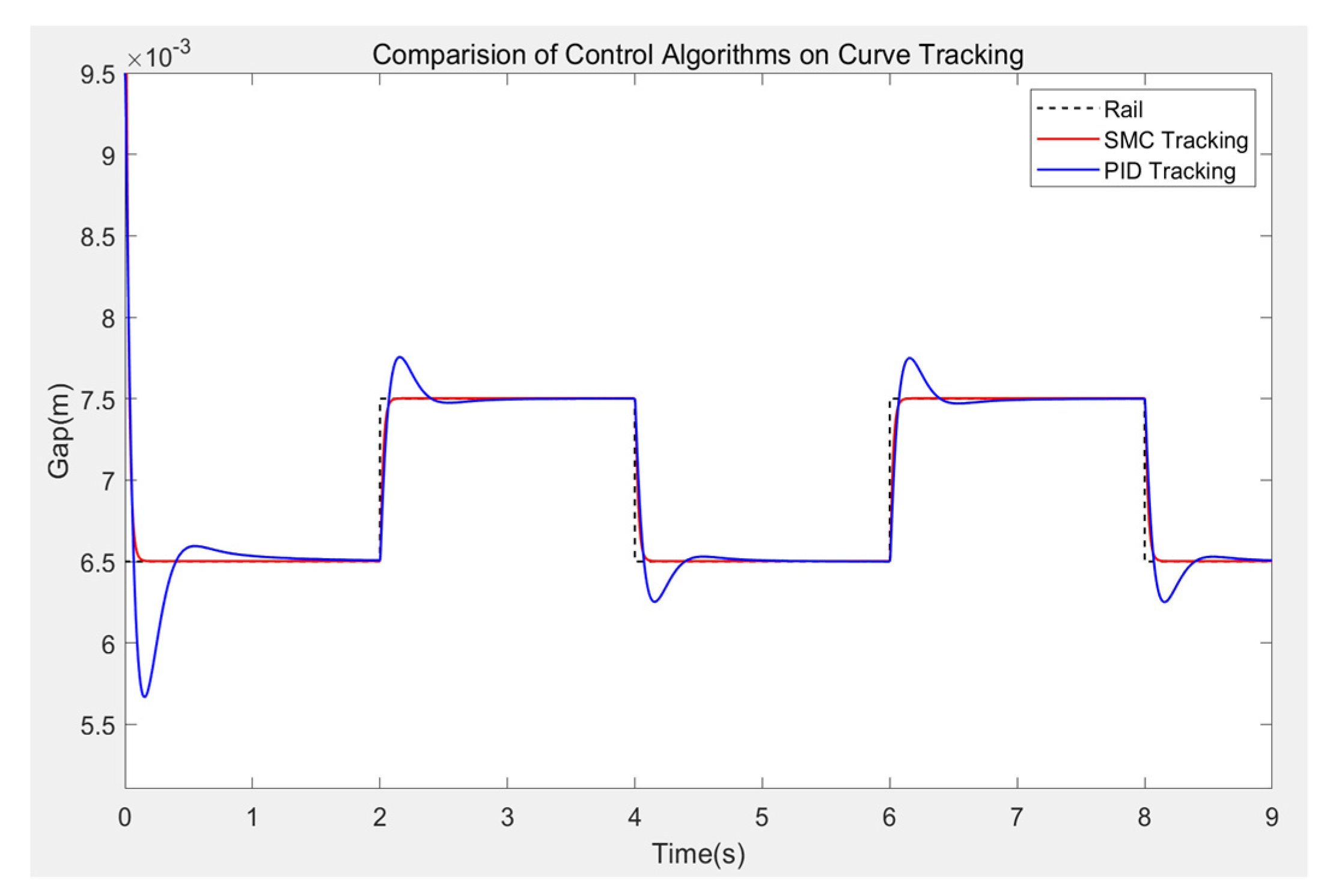
First, the expected gap is set to be 6.5 mm, and the initial suspension height of the maglev train is 9.5 mm. Under the square wave excitation with a period of 4 s and an amplitude of 1 mm, PID and SMC control methods are selected to complete the trajectory tracking experiment of the curve, with a running time of 9 s and a sampling time of 0.00025 s. The system response is shown in
Figure 8, and the partial enlarged view is shown in
Figure 9. It can be seen from the Figure that when the current input sliding mode control algorithm is adopted, the system follows the square wave better, there is basically no static error, and the adjustment amount reaches 95% at 0.08 s, basically meeting the adjustment requirements of the maglev train suspension system.
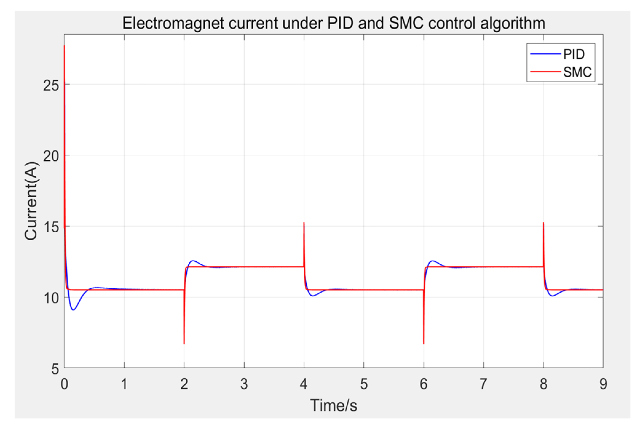
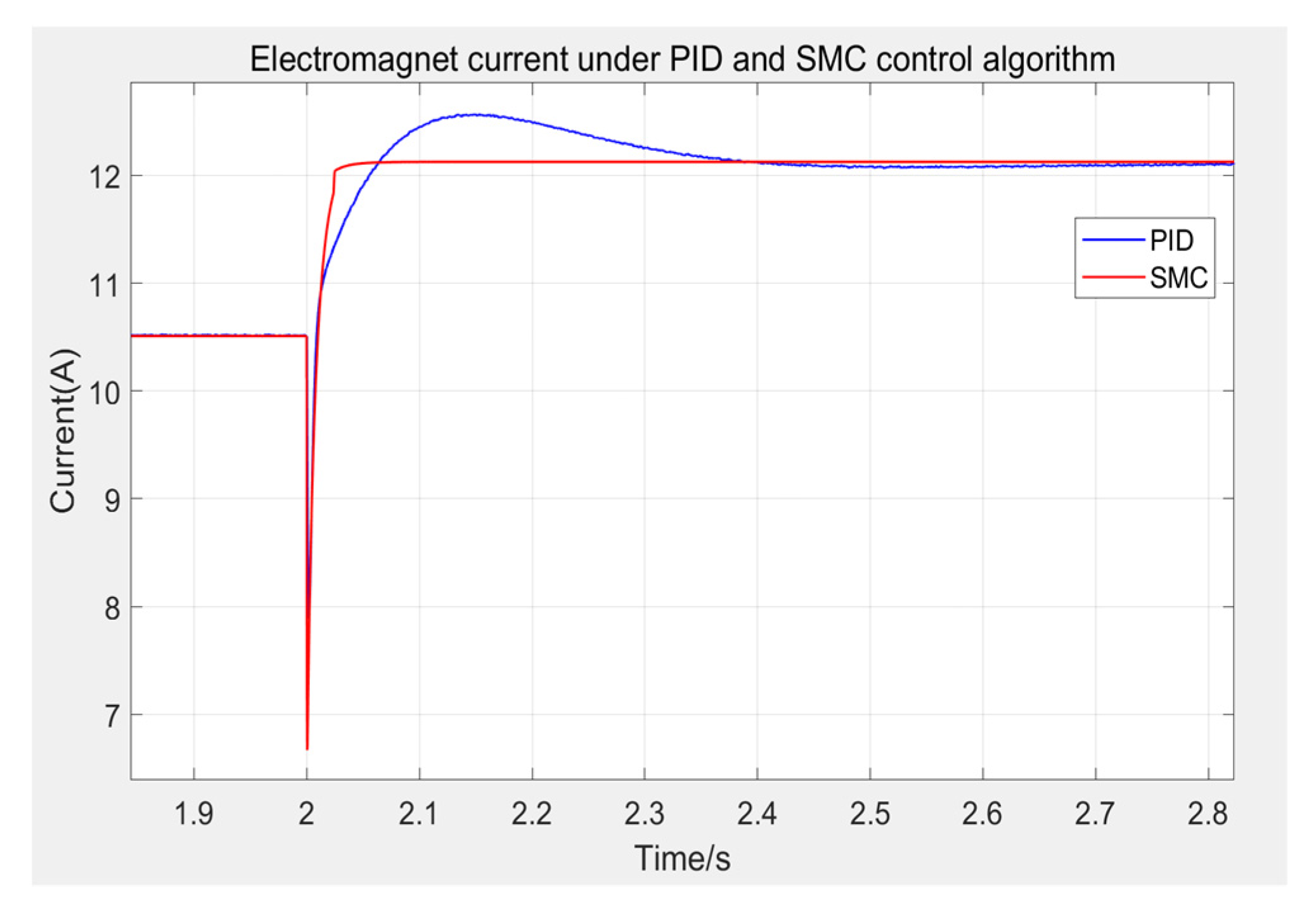
Next, observe the change process of control current when different control methods are applied, as shown in
Figure 10, and the partial enlarged Figure is shown in
Figure 11. From the simulation results, it can be seen that in the fluctuation stage, the current of PID and SMC control algorithms is relatively large, reaching about 27.8 A, but neither of them exceeds the 40 A voltage limit of the suspension hardware platform, and quickly fall back with the rising of the electromagnet. Under the control of SMC algorithm, when the suspension gap is 6.5 mm, the current is about 10.5 A, and when the suspension gap is 7.5 mm, the current is about 12.1 A. Compared with the PID control algorithm, the control quantity under the SMC algorithm changes more rapidly and will not produce a very large quantity to overshoot the suspension gap. It will not fluctuate up and down after reaching the new steady-state current. From the above results, the performance of the sliding mode controller proposed in this paper is better than the PID controller, and can better meet the performance requirements of maglev traffic.
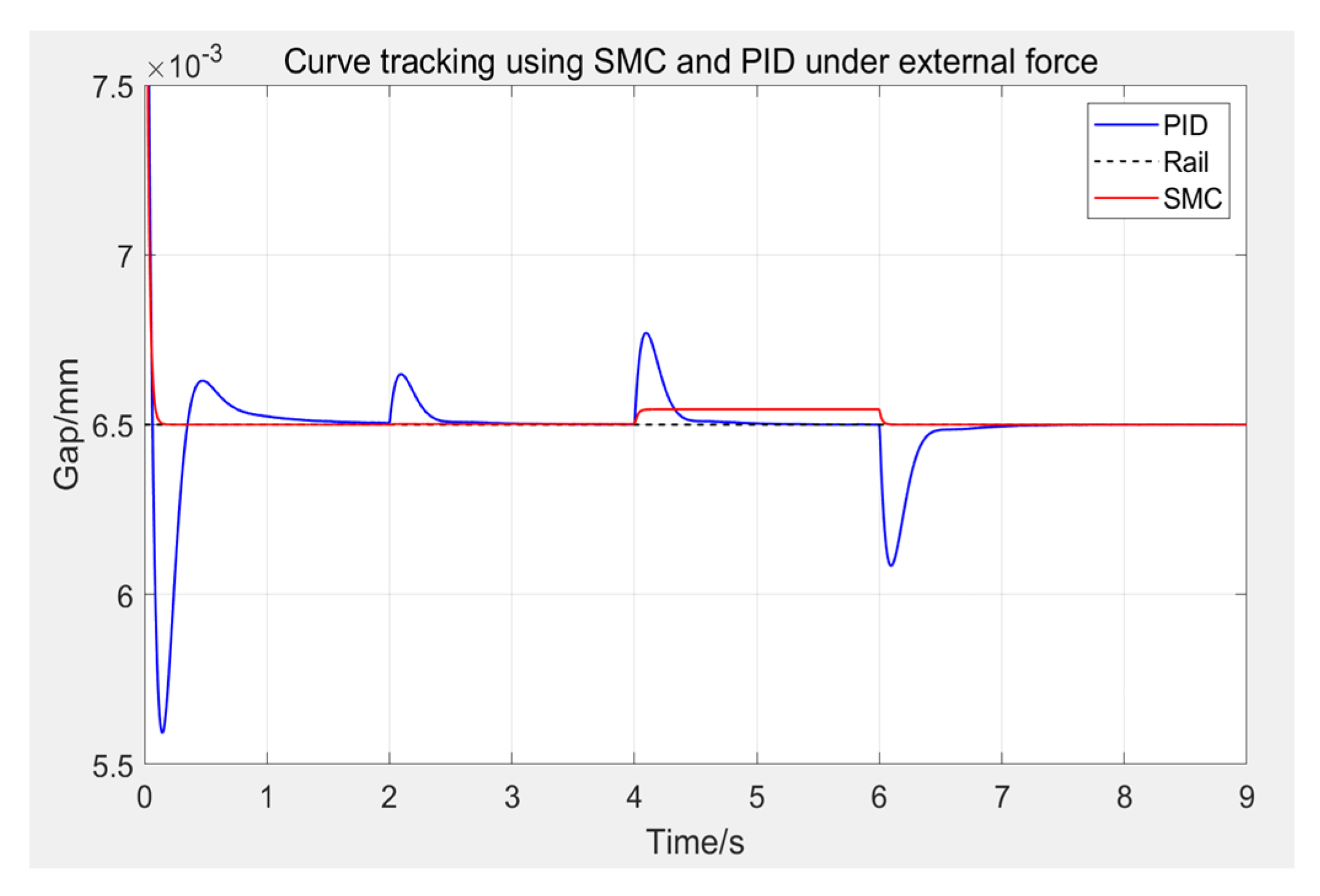
The levitation force of the maglev train would not only lift itself, but also the passengers. Therefore, the load of the train will change continuously during its running time, which will affect the control effect of the controller and test its ability to deal with external interference. To simulate this situation, external force interference is applied after the electromagnet is stably suspended at the working point, as shown in
Figure 12, and the partial enlarged Figure is shown in
Figure 13. After the electromagnet is stably suspended, an external force of 10% of its self-weight is applied to the electromagnet at 2 s, an additional 20% of the external force is added at 4 s, and the added external force is removed at 6 s.
It can be seen from the Figure that after the external force is applied, the SMC controller quickly recovers the steady-state value. When the external force is 10% of the weight of the electromagnet, the suspension gap almost has no fluctuations. When the external force is 30%, the SMC controller quickly reaches the new steady-state value of the gap, about 6.54 mm, and only needs about 0.06 s. Moreover, the tracking curve under SMC control does not fluctuate violently, nor does it produce overshoot. When the external force is removed, the suspension gap also quickly recovers to 6.5 mm without overshoot.
It should be pointed out that the new steady-state value of SMC controller will change when a large enough external force is applied. This is due to the fact that although the SMC controller has fast convergence and high robustness, it cannot eliminate the steady-state error. From Equation (40), when the applied external force is very large, namely, condition is no longer satisfied, the sliding mode function cannot converge to 0, thus a constant error will be generated. However, it can be seen that the constant error is very small, about 0.04 mm, which has no impact on the stability of the suspension system. Therefore, the anti-interference ability and robustness of sliding mode controller are better than PID.
4. Design of Sliding Mode Controller Based on Extended State Observer
To solve the problem of steady-state error in sliding mode control method, the linear extended state observer (LESO) in active disturbance rejection control algorithm can treat the internal uncertainty and external disturbance of the controlled object as “total disturbance”, estimate them in real time, and eliminate them by control law. The controlled object with disturbance, uncertainty, and nonlinearity is reduced to the standard integral series type. When there are many uncertainties, it can still maintain good control performance. Therefore, an extended state observer can be set to eliminate the disadvantage of steady-state error in sliding mode control.
4.1. Design of the Controller
Similarly, according to the design of the current loop in
Section 2, when
, the time constant of the current loop is very small, the voltage current transfer function can be approximately 1, and the system is reduced from third order to second order. For the sake of aesthetics, the symbol
in Equations (2)–(18) is removed. Take
,
,
, and the equation can be simplified as:
where
is the disturbance term after the synthesis of nonlinear factors and external disturbances, in order that the total disturbance is
, where
is the control input coefficient of the system, and the parameter setting is required. The following equation can be obtained:
Take
as a state variable for estimation, and let
, then the expanded state space is:
By designing the LESO according to the above formula, we can get:
where
,
, and
are undetermined coefficients, which can be configured as
according to the bandwidth method. At this time,
is the estimated state of
, let
and
be the output of sliding mode controller, and bring this into Equation (46) to obtain:
When the observation effect of the observer is good, namely, depending on the setting of parameter
, the total error is eliminated. At this point, the state space of the system changes to:
The sliding mode controller is constructed for the above system, and the error is defined as:
Select the sliding mode surface as:
The approach law is designed as:
Define the Lyapunov function as follows:
To make
, the controller is designed in combination with Equation (52) as follows:
Combined with Equation (49), the final control law is:
4.2. Simulation Analysis
A simulation model is built in Simulink of MATLAB for simulation experiments to verify its control performance.
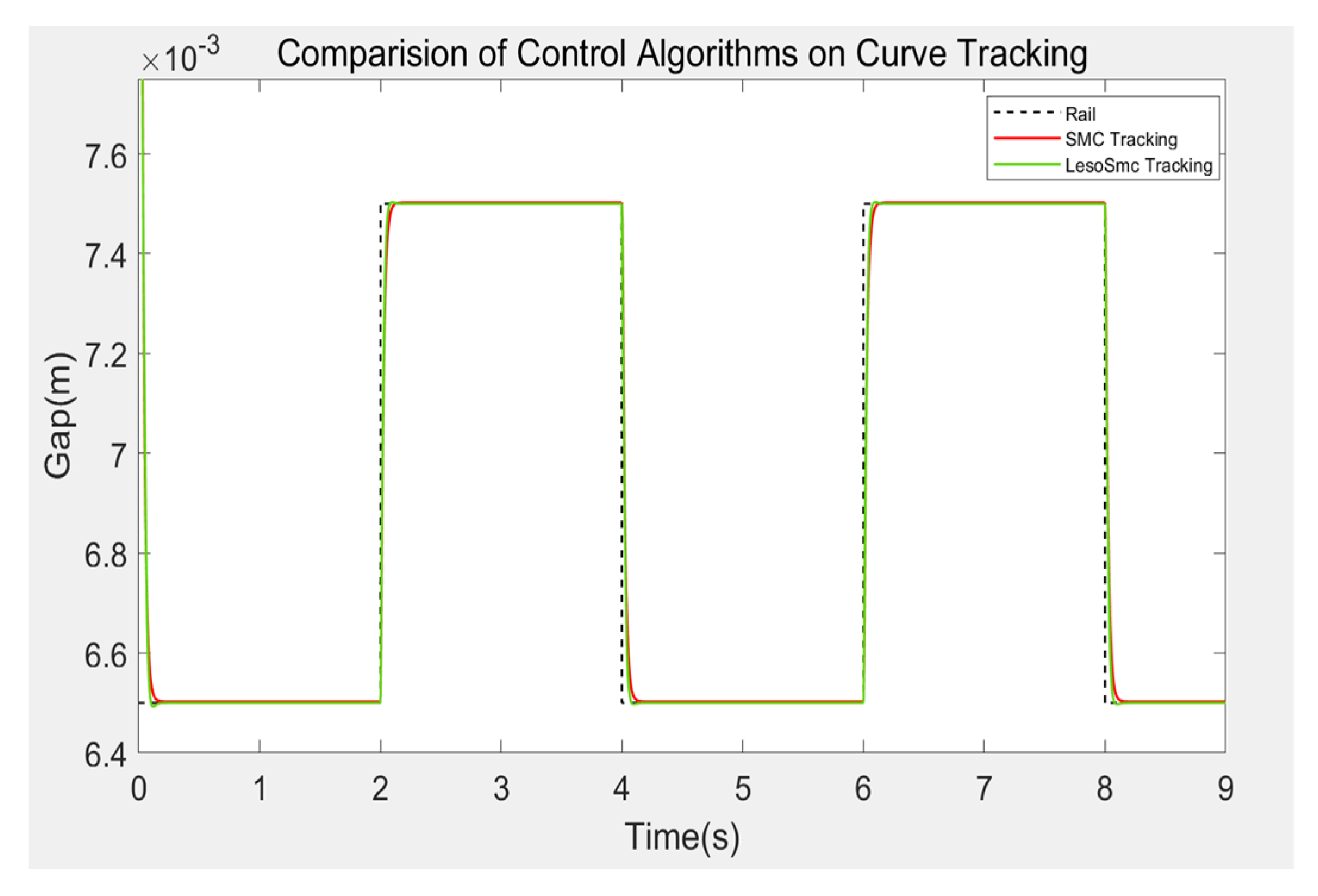
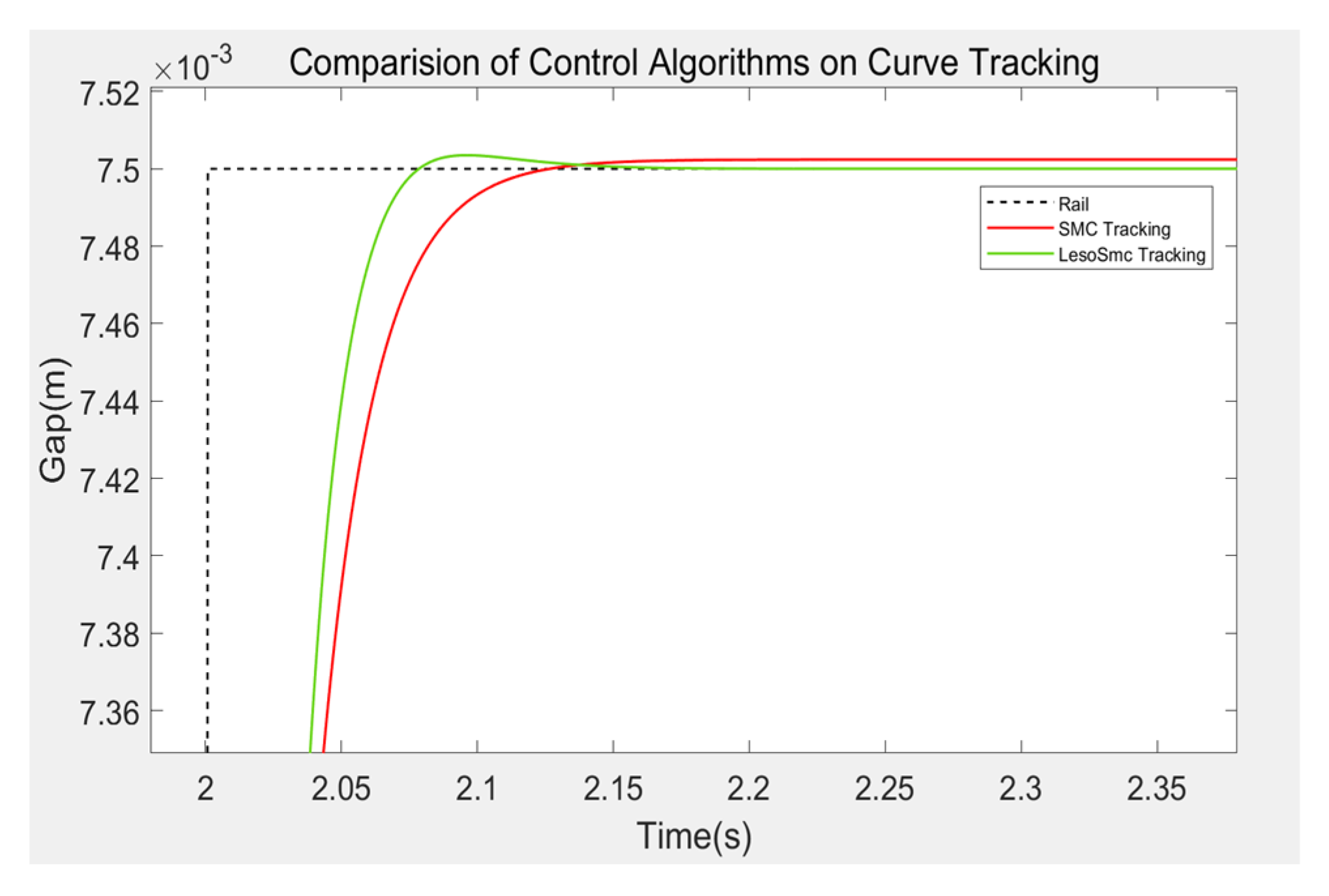
As in the third section, first, set the expected gap as 6.5 mm, and the initial suspension height of the maglev train as 9.5 mm. Under the square wave excitation with a period of 1 s and an amplitude of 1 mm, select PID and SMC control methods respectively to complete the trajectory tracking experiment of the curve, with a running time of 9 s and a sample time of 0.00025 s. The system response is shown in
Figure 14, and the partially enlarged Figure is shown in
Figure 15. From the Figure, it can be seen that when the sliding mode control algorithm based on the extended state observer is adopted, the system has better effect of following the square wave. Compared with the traditional sliding mode controller, it not only completely eliminates the steady-state error, but also has faster response speed. At 0.052 s, it reaches 95% of the adjustment, 35% faster than the traditional sliding mode control, and the gap approaches quickly first. Then, the desired gap is reached smoothly.
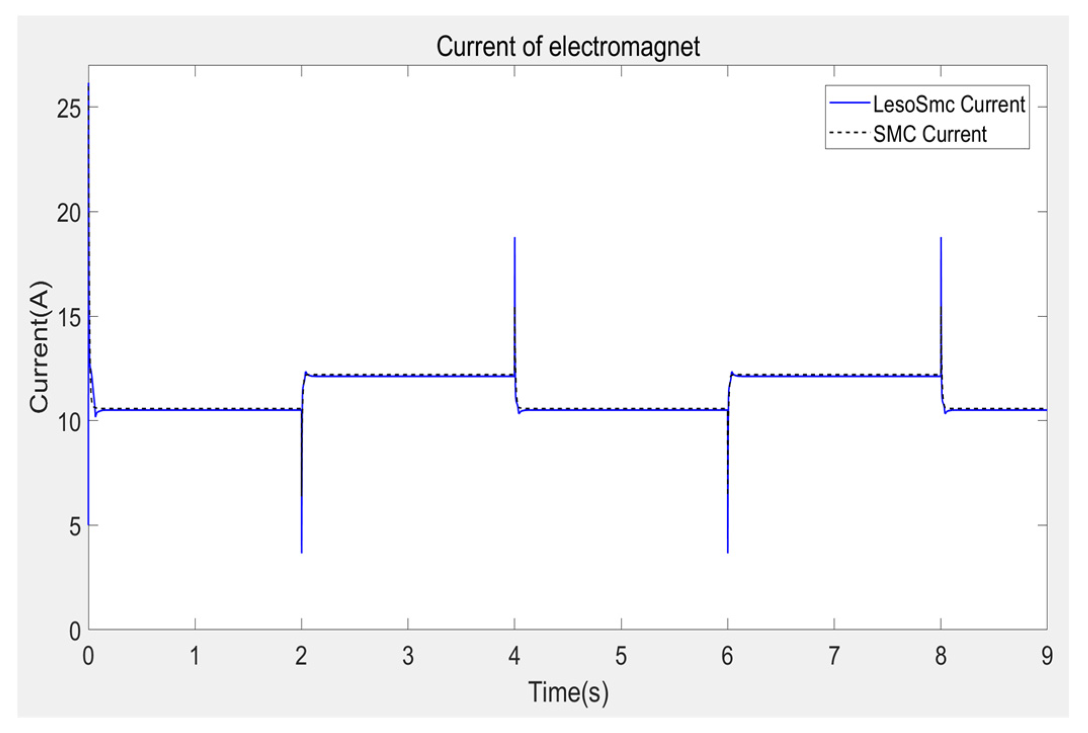
At the same time, the input current of the system is shown in
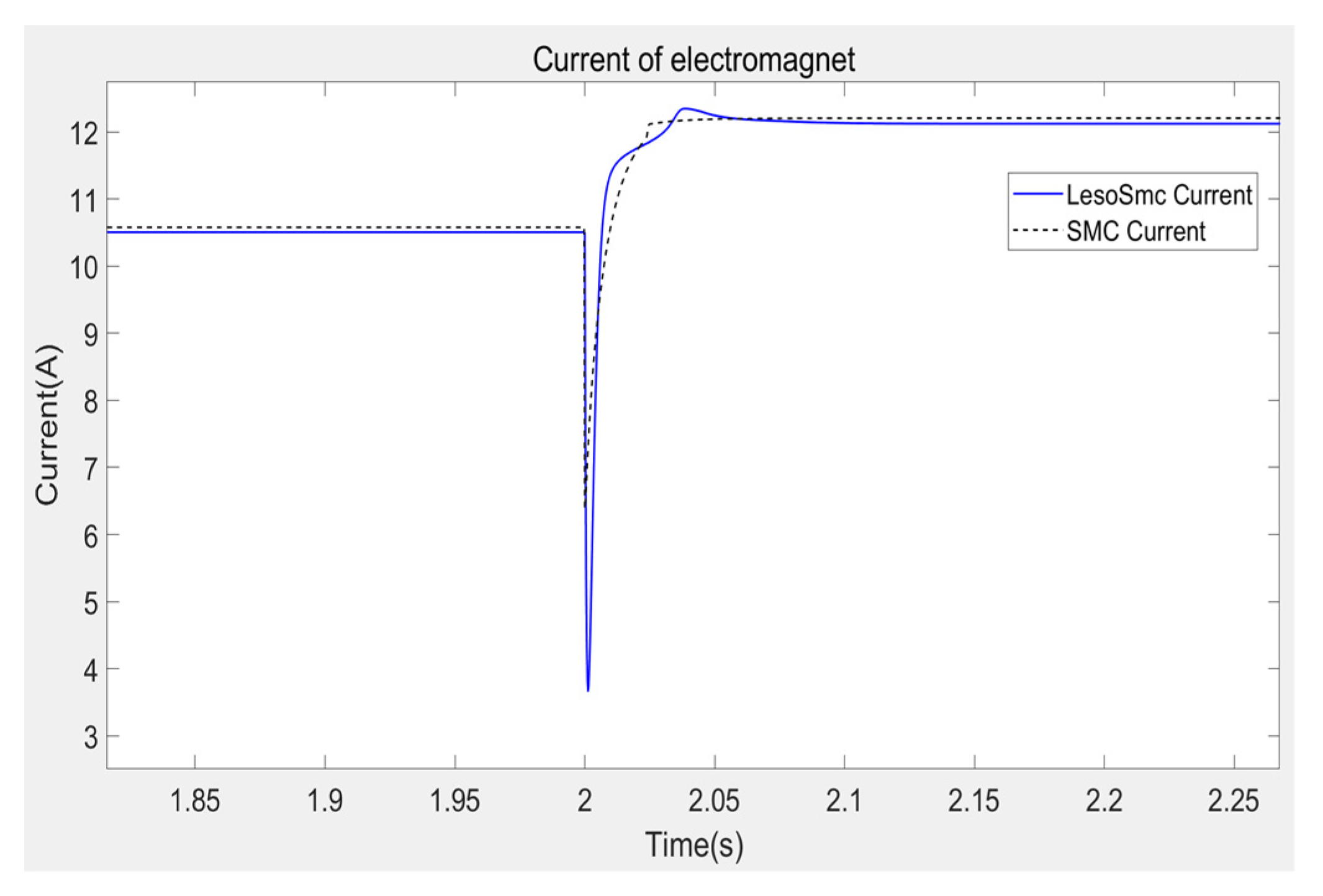
Figure 16 and the local enlarged Figure is shown in
Figure 17. It can be seen from the Figure that when the suspension gap is 6.5 mm, the current is about 10.5 A, and when the suspension gap is 7.5 mm, the current is about 12.1 A. The maximum current is about 26 A, and when the set suspension gap is 6.5 mm, the maximum current is 18.78 A, and the minimum current is about 3.66 A. Both of them did not exceed the 40 A current limit of the subsequent experimental platform, which was within the controllable range of the system. When the desired gap changes, the control current changes faster and smoother than the traditional sliding mode control.
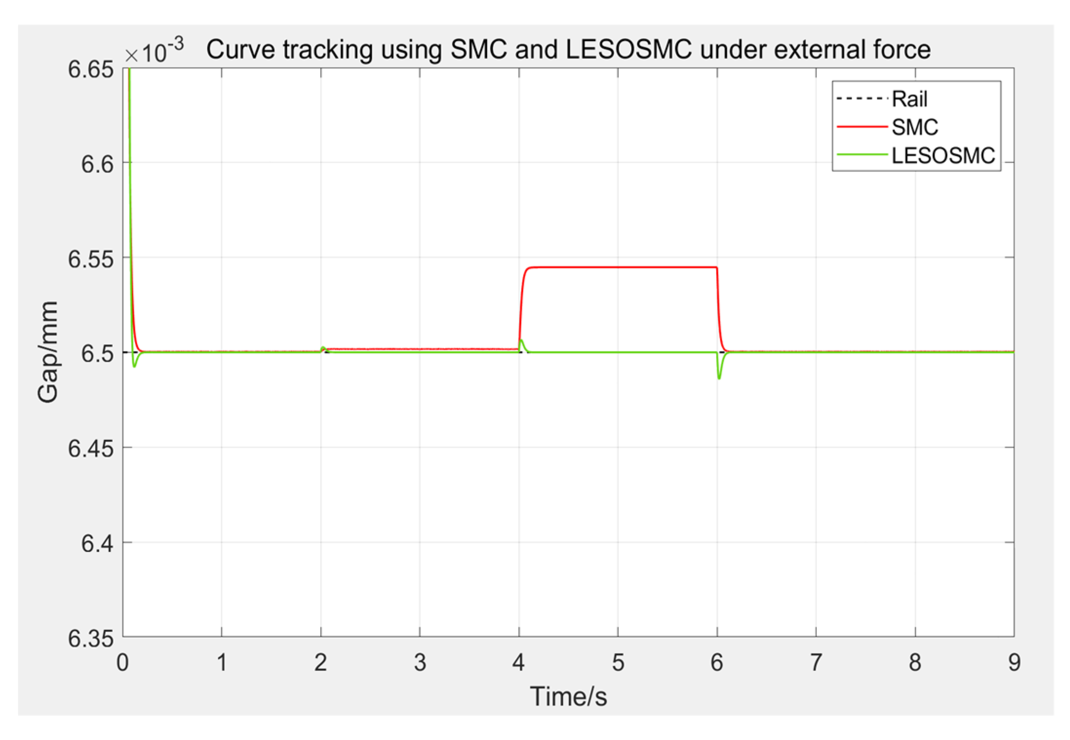
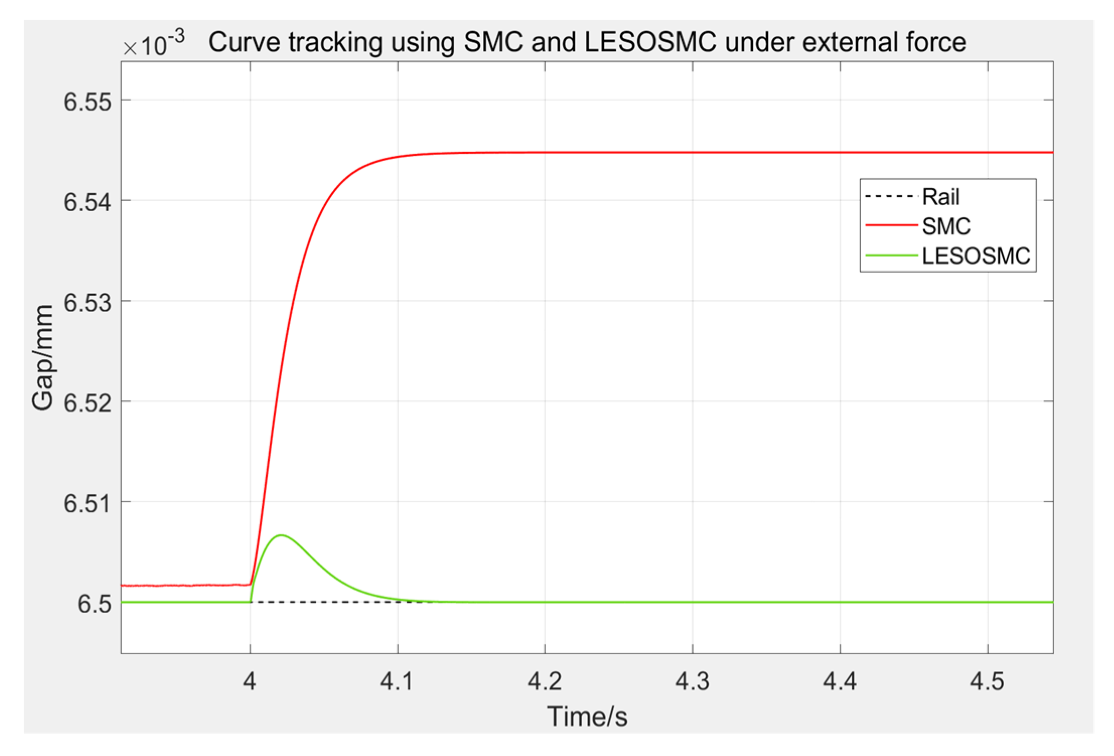
Similarly, to compare the anti-interference ability of the two controllers, simulate the load change of the maglev train in daily work, external force interference will be applied after the electromagnet is stably suspended at the working point, as shown in
Figure 18, and the partially enlarged Figure is shown in
Figure 19. Apply an external force of 10% of its self-weight to the electromagnet at 2 s, add 20% of the external force at 4 s, and remove the external force at 6 s.
It can be seen from the Figure that due to its control law, the traditional sliding mode control will produce an irreparable steady-state error when the load changes, and when the difference between the actual load of the system and the mass set in the control law becomes larger, the steady-state error will further increase. The sliding mode control based on the extended state observer will not have this problem. Since the linear extended state observer will estimate the total disturbance of the system and eliminate it in the control law, the suspension gap will quickly return to the expected value. When 30% of the self-weight of the electromagnet is applied, the system will produce a fluctuation of about 0.007 mm at the maximum value, and when the external force is removed, a fluctuation of about 0.02 mm will be generated. At about 0.087 s, the wave momentum is reduced by 95%, the fluctuation is almost negligible, and the speed of recovery to the desired gap is very fast. Therefore, the robustness and anti-interference ability of LESOSMC have been greatly improved on the basis of SMC.
5. Experimental Verification Based on Suspension Hardware Platform
The hardware platform used in this paper is a scaled down experimental suspension frame, whose structure and performance are similar to the actual scale maglev train platform. Using the TR81 series eddy current displacement sensor, the chopper is a half bridge chopper, which is the same as the low-speed normally guided chopper. See
Table 3 for specific parameters.
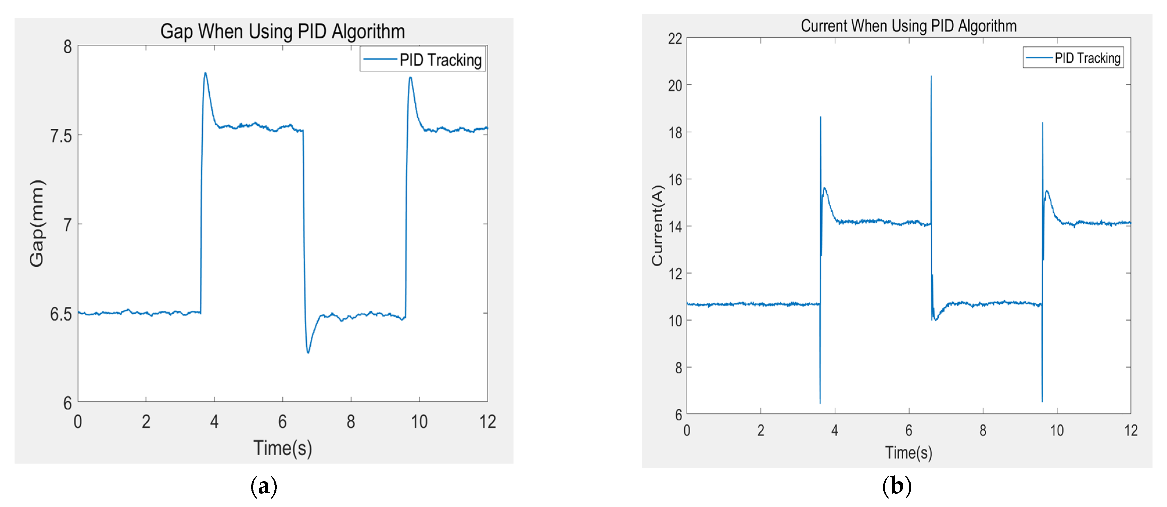
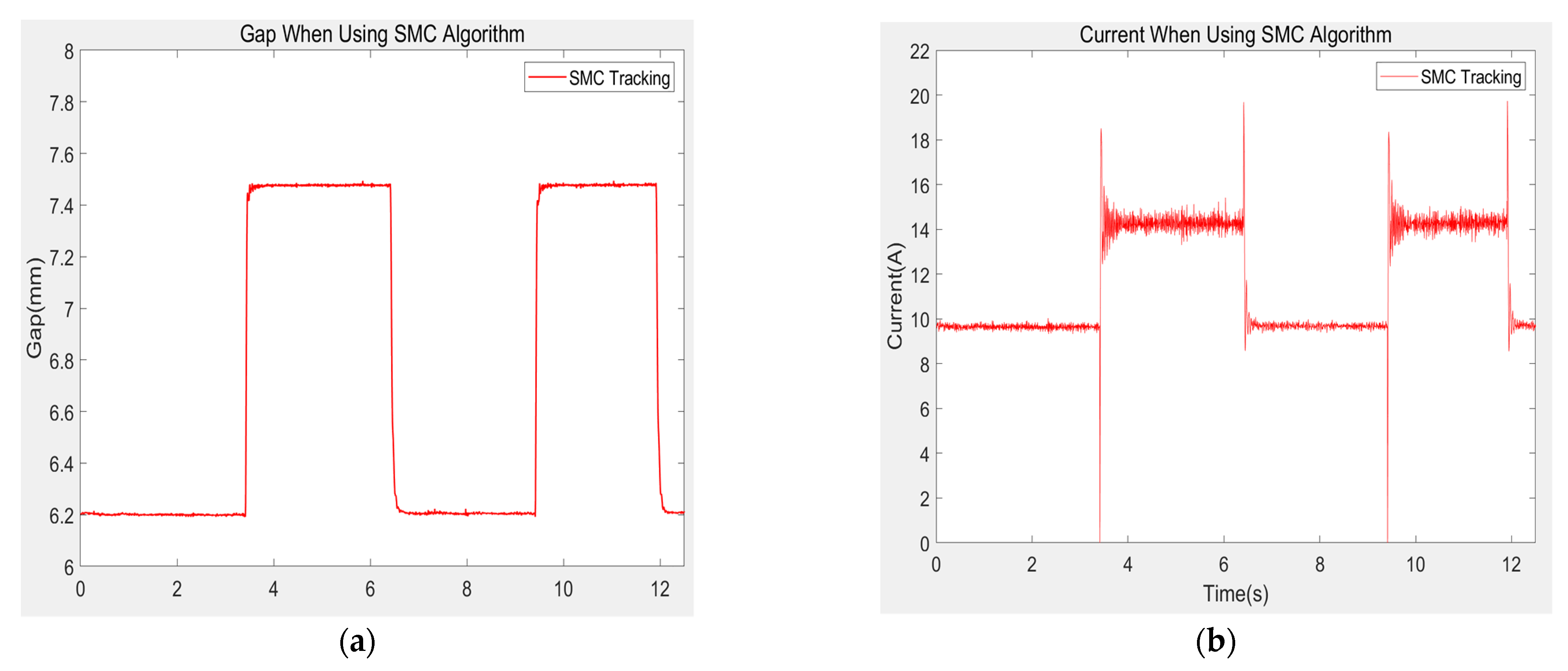
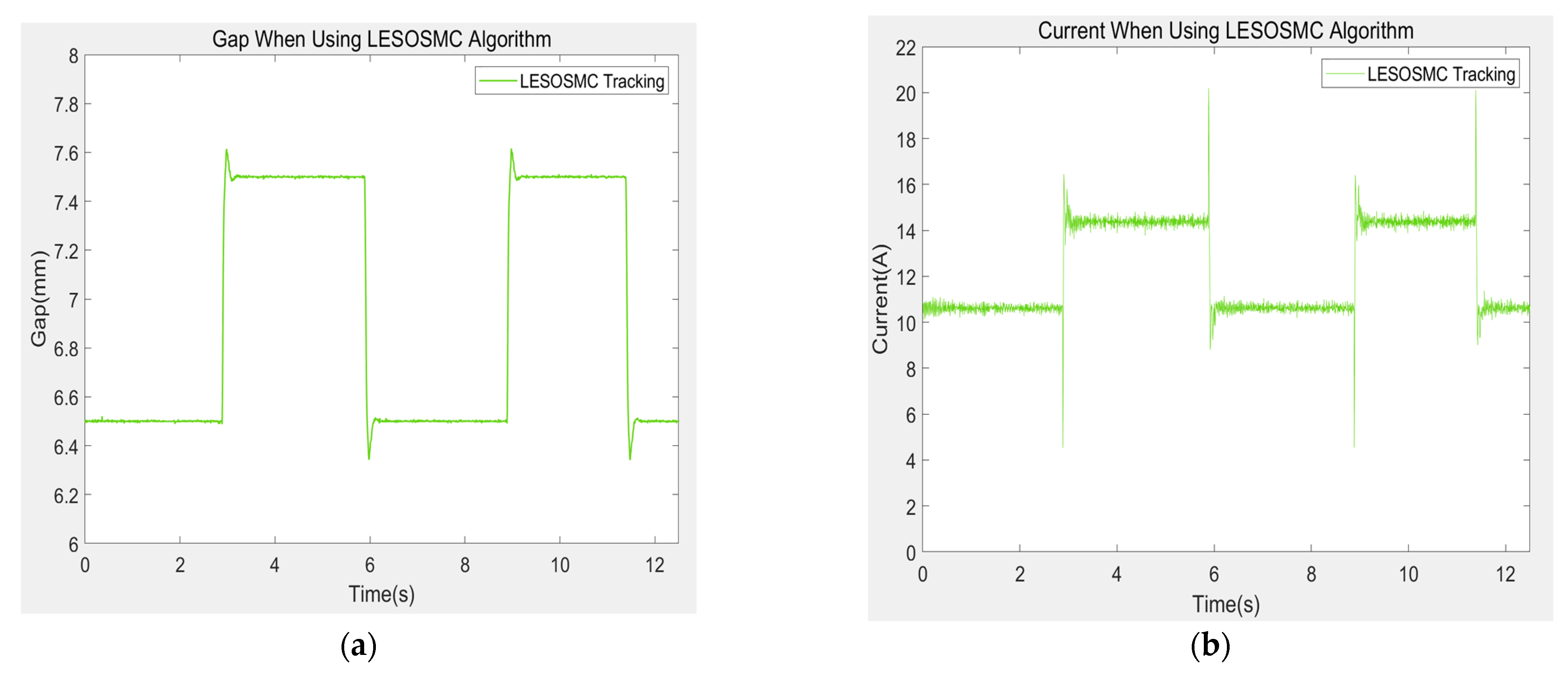
After the electromagnet is suspended stably, record the gap value of the electromagnet and the current value of the electromagnet coil. The sampling time of the control algorithm of the experimental suspension frame is 1/4000 s, and the sampling time of the recorded data is 1/200 s. The gap and current values of the three algorithms are shown in the Figure below.
Figure 20,
Figure 21,
Figure 22 and
Figure 23, it can be seen that the experimental results are consistent with the trend of simulation data. Under the excitation of 1 mm square wave, the PID algorithm produces nearly 38% overshoot and the recovery time is slow. The change of control current is relatively slow, which makes the system not only produce great overshoot, but also cannot be stable at the 6.5 mm working point, with some fluctuations up and down. Although the SMC algorithm has no overshoot, it produces a steady-state error of 0.3 mm, and there are many control current burrs and great mutations, which will bring great pressure to the hardware platform. After using LESOSMC algorithm, the system has only about 11.4% overshoot, and it only takes about 0.28 s to reach the new gap expectation value. Compared with PID algorithm, it is very stable and suspended near it after reaching 7.5 mm, with almost no fluctuation. Compared with SMC algorithm, its control current burr is smaller, the peak value of control current is smaller, and the mutation is smaller, which reduces the pressure on the system caused by the rapid and large change of current, therefore improving the stability of the system.
At the same time, during the process of applying and removing the external force of 10 and 30% of the self-weight of the electromagnet with the pull meter, the PID algorithm fluctuates greatly. Although it tends to recover to the 6.5 mm suspension gap value after the external force is applied, it is relatively slow. However, SMC algorithm can quickly reach the new steady-state value of suspension gap without overshoot after the external force is applied, but it will have steady-state error, which will increase with the increase of external force. Under LESOSMC algorithm, the system is hardly affected by external force. When the external force is applied, the maximum fluctuation is only 0.04 mm. After the external force is removed at about 3.2 s, the drop in gap is only about 0.11 mm, and it quickly recovers to the expected gap value of 6.5 mm.
6. Conclusions
In view of the strong nonlinearity, complex working environment, and easy to be affected by external disturbances of the maglev train suspension system, this paper designs a LESOSMC controller based on the SMC controller, which improves the performance and anti-interference ability of the system step by step. The effectiveness and stability of the designed controller are proved in theory, and verified by simulation and experiment. The results are consistent with the theoretical derivation. By comparing the control effect of PID and SMC algorithm, it shows that the curve tracking performance and stability of SMC controller are better than PID controller. On this basis, aiming at the shortcoming that SMC controller is prone to generate steady-state error, the linear extended state observer in the field of linear active disturbance rejection is applied to sliding mode control, which successfully improves the system performance, not only completely eliminates the steady-state error. However, this also further improves the response speed and anti-interference ability of the system. Therefore, a breakthrough in control effect is achieved, which provides an engineering practice reference value for the further application of maglev train.
