Abstract
This paper deals with the problematic of the drive system of small-diameter knitting machines (hereinafter “knitting machines”). An alternative design of a new drive system is presented that addresses the effective working position of selected operating elements, i.e., a cylinder, a dial, and a roller cutter. The design is protected by patent No. 303578, and the authors of this paper also authored the patent. For the description and simulation of the drive system, mathematical models have been elaborated of the existing and new drive system, which include an additional design of a more suitable stroke for the movement of the cylinder. The output of the simulations are the courses of kinematic quantities, torque, and electric current, elucidating the benefits of the new drive system. Based on the structure of the new drive system, a test device has been designed and manufactured to verify functionality and reliability. The new drive system consumes less energy, simplifies the machine frame and reduces noise emissions. The obtained results can help in researching the issue of knitting machine frames, and in addition, the new system brings new technological possibilities for knitting.
1. Introduction
Knitting machines are an essential part of traditional textile engineering with a rich history, though knitting technology is relatively young [1,2] compared to other areas of this industry. In addition to classic knitting technologies and their products, extensions of classic knitted fabrics with higher added value are increasingly coming to the fore [3,4,5,6,7].
Previously used in the drive systems of small-diameter knitting machines were mainly an asynchronous motor with short circuit “anchor” and graduated pulleys for changing speed [2]. The term “drive system” in this paper includes the motor, its control, and the transmission that propels the required elements, while the term “drive” includes only the motor and its control. After the development of semiconductor rectifiers, DC brush control motors were used relatively briefly. Today, frequency converters or control units for servo drives are used to change speeds in asynchronous motors [8,9]. In the past, the drive systems of small-diameter knitting machines contained relatively complex mechanisms with numerous mechanical transmissions installed in intricate, voluminous frames [10]. Mechanical transmissions set the limits of use of the operating elements forming the knitted fabric in terms of effective use throughout the entire work process [11]. Working elements mean the cylinder, dial plate (abbreviated as “dial”) and the roller cutter [12]. The dial in knitting practice is called a rotary element, used mainly to create an overhanging hem especially on socks, as well as to produce a solid beginning and in some types of machine also double-faced knit fabric [1]. An integral part of the dial is a roller cutter used for cutting yarn according to technological requirements. In the overhanging mode, i.e., the formation of an overhanging hem on the sock, it is essential to uphold the technological condition of mutual rotation between the cylinder and the dial [13]. This is due to the sliding out of the sinkers from the dial between the needles during rotation. The limit of the maximum rotation is given by the sum of the maximum plays in the gearing of the drive system given by its stiffness.
Theoretically, from the technological standpoint, the dial would be synchronized with the cylinder only for two revolutions during manufacture of the sock. The first revolution would be to catch the beginning of the knitted fabric and after knitting the hem, hanging the knitted fabric back on the needles [2]. The roller cutter is not dependent in principle on the movement of the knitting roller or the dial itself, so there is no need for synchronization [1]. In the past, there were knitting machines, especially for manufacturing delicate women’s stockings, which did not include the dial. On these machines, it was possible to create an overhanging hem even on the front side [8].
The percentage of utilization of the aforementioned operating elements (cylinder, dial and roller cutter) is significantly different during the process of creating sock goods, ranging from 5% to 100% [8]. The mentioned workload and length of the process during knitting was based on the creation of one classic sock with the top hem designed for the foot size EU 44, Figure 1. The knitting time of one sock is different and especially depends on its size, shape, material used and the variety of uses of colors and patterns required by the customer [14]. The current concepts of the drive systems do not allow flexible control of individual operating elements according to their current needs for inclusion in the technological process. This problem occurs due to the direct mechanical connection between the dial and the roller cutter; their movement is standardly derived by constant transmission by gears from the movement of the cylinder [15].
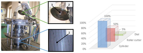
Figure 1.
Cylinder 1, roller cutter 2, dial 3 and their percentage load during the knitting process.
The application of controlled drives for the individual work elements mentioned above offers the possibility of increasing the efficiency of the knitting process and the associated significant savings in electricity consumption [16]. An indisputable advantage is the reduction of demands on the installation space and the overall simplification of the machine design due to the reduction of moving elements of the drive system [17]. It is worth mentioning that the gears making up the current drive system are also a key vibration exciter and noise source, so one expected benefit of using controlled drives is the reduction of noise pollution and ensuring improvement of health conditions for machine attendants [18]. Another important criterion for assessing the suitability of employing controlled drives is the demands on the dynamic properties of the machine, as their applications can bring an improvement in their properties, thanks to the possibility of a suitable choice of lift dependence [19,20].
This paper focuses on assessment of the new drive system compared to the existing one. The new drive system will respect the targeted inclusion of the cylinder, dial, and roller cutter in the technological process. The use of controlled drives in this area appears to be a possible way of increasing the degree of technical sophistication of small-diameter knitting machines. There are a number of varying structures of the drive system of small-diameter knitting machines. One of the most commonly used methods of designing the drive system of small-diameter knitting machines is shown in Figure 2 [2]. The principle of the system is based on the transmission of power to the cylinder (4) and to the dial (10) from the servo drive (M1) by a system of gears (1,2,3,5,6,7,8,9) and shafts (11,12,13).
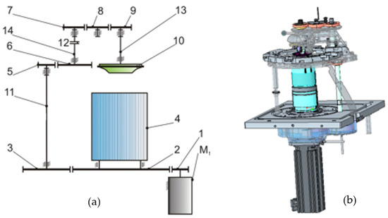
Figure 2.
Structure of the present concept of the small diameter knitting machine: (a) schematic view (b) 3D model.
The main movement of the knitting machine is performed by a brushless alternating servo drive (M1), a pinion (1), and a toothed rim (2), which is part of the cylinder (4). The dial drive system begins by transmission from the toothed rim (2) to the gear (3). The system continues through the shaft (11) to the gearing (5 and 6). The shaft (12) is fitted with a clutch. This clutch must ensure that its original position is precisely reset after the dial arm has been tilted (10), i.e., after disconnection of the drive system. Furthermore, the system connects the gears (7,8,9 (V)) to the shaft (13) of the dial (10), which is mounted and firmly connected to the roller cutter. The gears ensure the same angular velocity of the dial (10) and the cylinder (4). The delimitation of plays between gear teeth is realized by changing the axial distance between the gears in combination with split gears [21].
2. Mathematical Models
2.1. Existing Drive System of a Small-Diameter Knitting Machine
An analysis was performed of the existing design to assess the impact of the changes to the new drive system. The results of the analysis are compared with those obtained by analyzing the modified drive system in the following chapter.
To investigate the dynamic behavior of the drive system of a small-diameter knitting machine, a discrete model was elaborated, including the torsional compliance of all main shafts and the cylinder. The actual mathematical model of the knitting machine drive system in Figure 3 was formulated while considering the following assumptions:
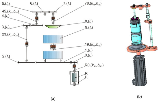
Figure 3.
Existing small-diameter knitting machine drive system-(a) Mathematical model, (b) 3D model.
- Gears (0–7) and the dial (8) are considered as perfectly rigid bodies
- Each of the shafts (R0, 23, 45, 78) is replaced in the model by two geometrically identical shapes whose moments of inertia are included in the moments of inertia of the corresponding gears. In the case of the shaft (78), the moment of inertia of its lower part is included in the moment of inertia of the dial (8). The relevant shapes are connected by non-material elastic elements with torsional stiffnesses and viscous damping elements.
- The cylinder (9) is replaced in the model by two geometrically identical shapes, whereas the moment of inertia of the lower shape is included in the moment of inertia of the gear (1). Both shapes are connected by non-material elastic elements with torsional stiffnesses and viscous damping elements.
- The moments of inertia of the needles and sinkers are included in the moment of inertia of the cylinder (9).
- The moments of inertia of the sinkers are included at the moment of inertia of the dial (8).
- In the calculation, plays in gears are considered, which are simply entered into the mathematical model using angular deflections of shafts R0, 19, 23, 45, 78; the play in the shaft bearing is not considered by the model.
- The model does not consider the bending compliance of shafts and the thermal expansion of materials.
- The model does not consider gravitational and friction forces and forces caused by the tension of the yarn.
- The model does not consider the force required for cutting the ends of the yarn.
The required moments of inertia of the individual elements of the drive system were determined using the cad model of the drive system, see Table 1. Conversions appearing in the equations of motion are given in Table 2. The designation and position of the elements correspond to the diagram in Figure 4.

Table 1.
Moments of inertia of the considered parts of the drive system.
Table 2.
Gears appearing in equations of motion.
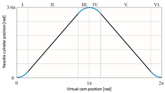
Figure 4.
Input stroke.
Lagrange equations of the second kind were used to elaborate the actual equations of motion of the discrete model of the drive system. This is among the most widely used methods of analytical mechanics, especially in more complex mechanical systems [22,23].
2.1.1. Form of the Lagrange Equation of the Second Kind
EK is the kinetic energy of the system, EP is the potential energy of the system, Rd is the Rayleigh dissipation function, and qi is the generalized coordinate.
for: i = 1, 2, …, n.
Matlab R2022a software and its Simulink module were used to solve the system of equations of motion. The individual equations were written in matrix form (1) and then solved by gradual integration in the Simulink environment, see Figure 4.
2.1.2. Listing of Matrices Used in the Equation (2)
Moment of Inertia Matrix I
Damping Matrix B
Stiffness Matrix K
Listing of vectors of generalized coordinates q and their derivatives
where I is the moments of inertia matrix, B is the damping matrix, K is the stiffness matrix, and q is the rotation vector of the selected elements of the drive system. The coefficients of torsional stiffness k, viscous damping b of the selected elements of the drive system were taken from a study [24]. Furthermore, in the equations of motion, conversions μ appear between the individual stages of the drive system. In the mathematical model of the drive system, the toothing plays are respected. These plays were included in the drive system using the conditions specified in the study, which replace the actual plays with angular deflections [25].
For Ange series knitting machines, a lift dependence is often used containing a polynomial of the 3rd degree describing the desired position of the cylinder in the start-up and run-out areas of the drive system. Linear sections appear in the lift dependence in which a constant velocity of the cylinder is required. The position of the cylinder is a function of a virtual cam corresponding to one of its revolutions, during which the cylinder performs a symmetrical reciprocating rotational movement between two dead centers from the start position to the end position in the range of 0–3/4 π, see Figure 4 [26].
Through the use of the elaborated solver [27] (see Figure 5) of differential equations, the gained motion Equation (2) was solved [28], and responses were observed in the relationship between the drive system and the kinematic excitation of the system, which was the desired course of acceleration of the drive system drive element during reverse motion. The reverse motion mode was selected for analysis due to the highest degree of dynamic loading of the entire knitting machine [24].
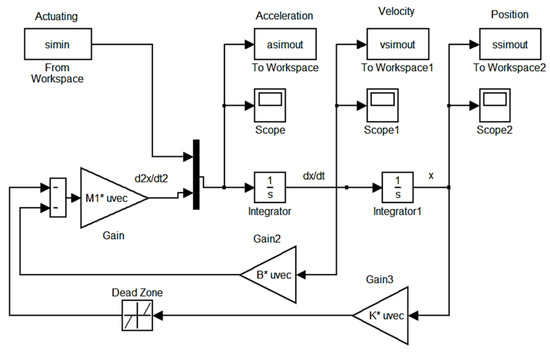
Figure 5.
Schematic of the differential equation solver in Matlab R2022a-Simulink software, MathWorks, Natick, MA, USA, Humusoft s.r.o. (distributor for the Czech Republic).
The output of the analysis are the courses of kinematic quantities of individual elements of the drive system (see Figure 6, Figure 7 and Figure 8), the designation of the elements corresponds to the diagram in Figure 3. The achieved angular velocity of the 16.8 rad·s−1 cylinder technologically corresponds to the highest recommended operating velocity of the Ange series small-diameter knitting machine in the reverse motion of the drive system using standard materials for production of sock goods [2].
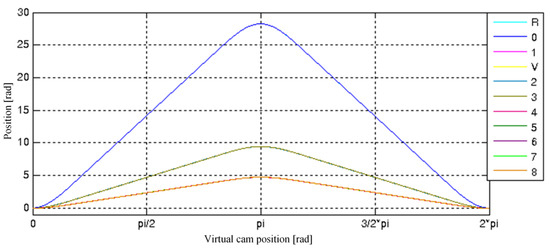
Figure 6.
Courses of positions of individual drive system elements.
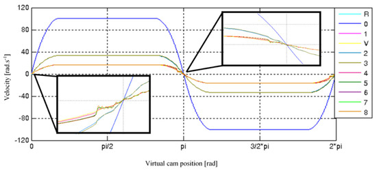
Figure 7.
Courses of angular velocities of individual drive system elements.
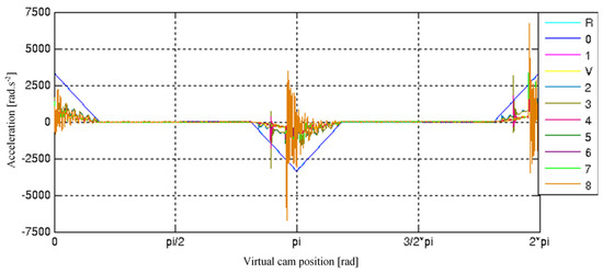
Figure 8.
Courses of angular accelerations of individual drive system elements.
The results of the analysis point to the theoretical influence of plays in the system of the knitting machine drive. These cause shock forces during their delimitation; this phenomenon can be clearly observed during the acceleration of the system in the form of maximum oscillation values (see Figure 8). Similarly, although not so significantly, delimitation of plays appears in the course of angular velocities of Figure 7, and there are evident oscillations, especially in the areas of motion dead points. In addition to play, these oscillations are also influenced by dynamic system parameters. Some of the curves overlap in the courses, and this phenomenon is particularly evident in the course of the position.
2.2. Modified Drive System of a Small-Diameter Knitting Machine
The newly designed structure (see Figure 9a) is protected by a patent [17]. The structure removes the part of the existing drive system that sets the dial with roller cutter in motion and further extends the basic driving unit (P1) by two additional controlled drives (P2) and (P3) for individual control of the dial (10) and the roller cutter (11). The functional model of the roller cutter drive system comprises a friction transmission mechanism in which the power transfer between the drive (P3) and the roller cutter is performed by a flexible shaft (13) fitted with a drive wheel (12).
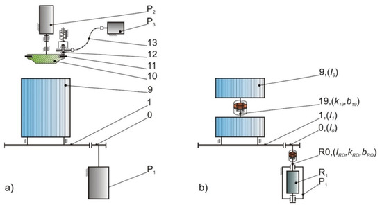
Figure 9.
(a) Structure of the modified drive system of the cylinder, dial and roller cutter with controlled drives (b) considered mathematical model of the modified cylinder drive system.
The gearbox containing the gearing (0–1) and the drive (P1) were taken from the existing machine structure to control the cylinder (9 (V)). In reverse motion of the modified drive system, only the cylinder is driven. This fact corresponds to the elaborated mathematical model of the part of the modified drive system in which only the cylinder is driven, see Figure 9b. The dynamic analysis of this part of the modified drive system was carried out in a similar way, considering the same assumptions and using the same solver of differential equations as the dynamic analysis of the existing structure of the drive system (Section 3), see the following list of matrices.
Matrices moment of inertia I, damping B and stiffness K
Listing of vectors of generalized coordinates q and their derivatives
The modified drive system is conceptually divided into three independent subsystems, each of which has its own drive (P1, P2 and P3). Individual subsystems are placed in service with different requirements for the prescription of movement depending on the technology being implemented. For this reason, individual theoretical movement cycles have been introduced for the cylinder, the machine and the roller cutter.
Based on the previous analysis of the existing drive system, a lift dependence was proposed containing a polynomial of the 7th degree for the system start-up and run-out areas, see Equations (3)–(5). The chosen polynomial degree appears to be a suitable means to suppress shocks in the drive system, to achieve more favorable courses of kinematic quantities, and it is also assumed that the drive is more capable of maintaining the required course.
Figure 10, Figure 11 and Figure 12 show the courses of the position, angular velocity and angular acceleration of the elements of the modified drive system. The dial with roller cutter and their corresponding part of the drive system are no longer in the dynamic analysis of the drive reverse motion mode, so the results do not indicate their corresponding courses. By using a polynomial of the 7th degree in the stroke, the course of kinematic quantities was smoothed. This benefit contributed to a significant reduction of the oscillation amplitudes of the modified drive structure compared to the existing structure in which a polynomial of the 3th degree was used. This decrease is best apparent on the courses of angular velocity and angular acceleration, see details in Figure 11 and Figure 12, in these courses there was a significant reduction of oscillations, especially in transition areas.
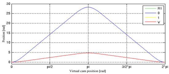
Figure 10.
Courses of positions of individual drive system elements.
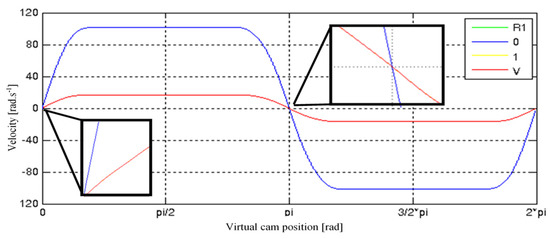
Figure 11.
Courses of angular velocities of individual drive system elements.
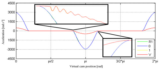
Figure 12.
Courses of angular accelerations of individual drive system elements.
The working speed is intended for classic materials of sock goods (Cotton, Lycra, Polypropylene, Moira and others). The knitting machine would be able to work at higher speeds and therefore it would be possible to achieve higher productivity, but the classic sock materials set a limit in the form of yarn strength [1].
2.3. Modified Drive System of a Small-Diameter Knitting Machine
A reduction in the number of elements in the modified drive system caused a decrease in the moment of inertia and plays, which then led to a noticeable suppression of transient oscillating phenomena resulting from delimitation of plays Differences between drive systems are particularly pronounced in angular acceleration courses. The maximum values during acceleration decreased significantly by up to 51%, and proportionally thereby the dynamic forces generated in the drive system as well. By increasing the degree of the polynomial in the lift dependence, we achieved more favorable courses of kinematic quantities of the drive system elements, as well as enhanced the ability of the drive to maintain the desired value.
The aforementioned adjustments appeared in more favorable courses of theoretical torques and theoretical electricity consumption of the modified drive system in comparison with the existing system, see Figure 13 and Figure 14, using different lift dependences. The decrease in total electricity consumption reached 10%.
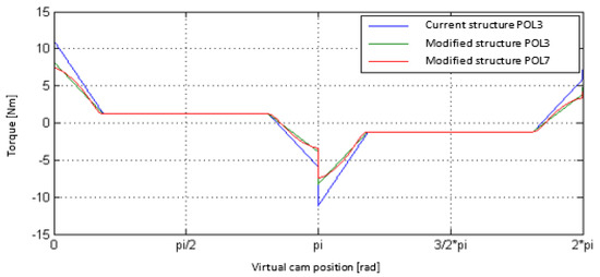
Figure 13.
Course of torques during one period of reverse motion of the P1 drive of the investigated systems, application of polynomials of the 3rd and 7th degree in the lift dependences describing the position of the cylinder.
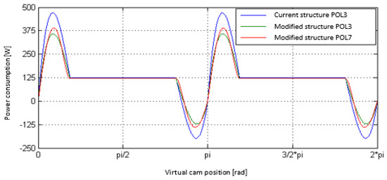
Figure 14.
Course of power inputs during one period of reverse motion of the P1 drive of the investigated systems, application of polynomials of the 3rd and 7th degree in the lift dependences describing the position of the cylinder.
3. Experimental Verification of the Drive System
For testing purposes and verification of the modified drive system of the small diameter knitting machine, a mechatronic test dial was assembled, see Figure 15, on which the previously acquired knowledge was applied. The test equipment is primarily adapted to verify the applicability of the modified system, i.e., to simulate the overhanging mode with emphasis on meeting the requirement for the maximum position deviation between the rotation of the cylinder and dial, and for application of lift dependences to the cylinder drive. The issue of cylinder and dial deviation with the replacement of mechanical bond by electronics was addressed in the study [26]. The test equipment contains no transmissions compared to the real machine. To capture the transmission between the cylinder and its motor, the flywheel 1 representing the cylinder rotates at a six-fold angular speed. Flywheel 2 represents the machine. Using the law of conservation of (kinetic) energy, we determined their reduced moments of inertia [29]. Flywheel 1 has two geometric designs. In the case of the existing drive system, the moment of inertia is 5.09 × 10⁻⁴ kg·m2, and in the case of the modified drive system, it is 4.15 × 10⁻⁴ kg·m2. The flywheels are mounted on the output shafts of servo drives 3 and 4, which are mounted to the frame 5. Type of servo motors used CTM4-07 (Control Techniques). Another part of the measuring dial were frequency converters 6, 7 UNI1405 (Control Techniques) and a computer 8 with the corresponding control system of the MotionPerfect V4 Program, Control Techniques software, Stafford Park 4, United Kingdom, distributor for the Czech Republic Control Techniques Brno s.r.o.
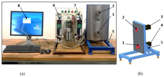
Figure 15.
(a) Apparatus used during measurement-measuring workplace (b) CAD model of the test equipment of the modified knitting machine drive system.
The structure of the control and simultaneously measuring system is composed of two complementary parts. The lower control level contains the basic settings of motion feedback control parameters using CTSoft software. These low-level settings allow the user to control strokes, properties and speed feedback loops and current controller parameters, but are not able to ensure the generation of more complex trajectories. For that reason, the higher program platform was created for the Motion Processor Plus module using the SyPTPro (System programming toolkit for drive automation systems) development environment. The APC (Advanced Position Controller) programming tool was used to create user programs. A complex control program was created implementing the synchronization of servo drives, automated parameter setting, measuring and recording system, and the desired position generator. The basis for obtaining information for both used servo drives (CTM4-07, Control Techniques, Stafford Park 4, Telford, UK, distributor for the Czech Republic Control Techniques Brno s.r.o.) is their own integrated sin-cos encoder, the output of which is information about the position of the shaft depending on the position of the virtual cam. The sin-cos encoder has a 32-bit resolution.
A sampling step of one tenth of an angular degree was chosen as a compromise solution. One revolution of the virtual cam was thus sampled into 3600 discrete values. Programs created in the APC requiring the sampling period to be set to 500 μs so that the control unit is able to properly complete all operations related to the main control loop period with generator, synchronization, measurement and data storage. The sampling frequency during the measurement was therefore corresponding to 2 kHz or 0.5 kHz. For individual measurements, the length of the measured section was chosen for 5000 samples, which corresponds to 2.5 s or 10 s in the time domain at the given sampling frequency. The measured data was stored in the integrated memory of the module and after stopping the run, it was downloaded separately via a serial communication channel to the PC, where it was interpreted using the mathematical programming tool Matlab. In the program created in the APC interface, the only controlled quantity is the position, which is also given by the feedback.
The movement mode of reverse motion of the machine was investigated on the test equipment. During reverse motion measurement, two flywheels differing in mass were applied, which simulated the existing and modified system, as well as two different lift dependences.
Measurements were used to verify the findings of previous analyses, which confirm that a reduction in the moment of inertia of the modified roller drive system in combination with an appropriate lift dependence can pave the way for a reduction in the maximum acceleration at the limits of movement intervals during reverse motion of the drive system. These changes resulted in a 38% decrease in the maximum value of position deviation (see Figure 16) and in a 31% decrease in the value of active current (see Figure 17). The biggest differences were observed in the area of transitions at the limits of movement intervals, especially when changing the sense of rotation. Kinematic values were obtained from the data of the connected sin-cos encoder.
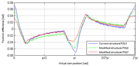
Figure 16.
Courses of needle cylinder position deviations, during reverse motion, in all designs at a velocity of 160 min−1.
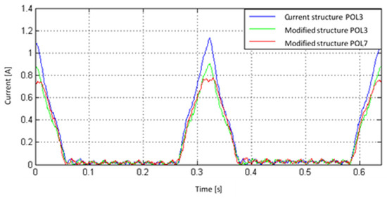
Figure 17.
Course of current in drive M1, during reverse motion, in all designs at a velocity of 160 min−1.
Figure 18 shows the courses of the position deviation in the standard velocity range during steady cylinder running conditions. The velocity range (160–200 min−1) recommended by the manufacturer [21] is used during the knitting of the tubular part of the sock, depending on the type of material used. When operating the drive in the specified velocity range, it can be concluded that the value of deviations depending on RPMs is negligible.
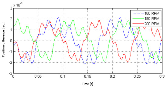
Figure 18.
Courses of needle cylinder and dial position deviations after stabilization of their movement, for velocities of 160–200 min−1.
In a real knitting machine, a transmission is installed due to the technological and dynamic parameters of the cylinder drive system, therefore the resulting value is usually extended by the value of the play in the transmission. This play may reflect in the position control accuracy of the cylinder. The possibility of eliminating this play to achieve higher accuracy can be achieved, for example, by direct control of the position of the cylinder using appropriate position sensors, or by using a gearbox without play. It can be assumed that the obtained measurement results, in particular the deviations of the position between the cylinder and the dial, will also correspond to the real modified drive system using optimal drives, their control and adjustment.
4. Verification of the Implementation of the Individual Roller Cutter Drive System into the Existing Structure
Figure 19 shows the implementation of a functional model of an individual roller cutter drive system into the existing installation of a small-diameter knitting machine. The CAD model is comprised of several subgroups and was created in the software Creo parametric 7.0.1.0. The first structural unit is a modified dial 1 serving as a bearing for the roller cutter 2. Another subgroup is formed of the pinion 3 fitted with a rubber ring in the circumferential groove and its installation in the bearing 4 built into the defined machine space. The roller cutter and the pinion form the whole of the friction transmission. The last part is the pinion drive, which is implemented by means of a stepping motor 5 and flexible shaft 6. A flexible type of shaft was used due to the position of the motor outside the lift arm 7 on the joint. This solution led to preventing an increase in arm weight, which would mean a reduction in ergonomic comfort for the machine attendant.
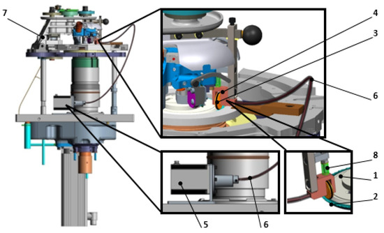
Figure 19.
CAD-model of the installation of a functional model of the individual roller cutter drive system into the Ange 18.1 small diameter knitting machine.
The pinion placement allows vertical movement of the fork, which is influenced by the pressure of the spring 8. This design variant has been designed for two reasons. The first ensures the regulation of the normal force by pre-stressing the spring and its optimum setting, so as to avoid pinion slipping or unnecessary overload. The second reason is the function of creating a flexible element compensating for manufacturing inaccuracies, in particular the flatness of the contact surfaces of the roller cutter and the pinion.
Figure 20a shows the installation of an individual roller cutter drive system on a real machine. A small-diameter knitting machine Ange 18.1 (Uniplet Trebic a.s., Czech Republic) was selected for positioning the drive system; its drive structure corresponds to the diagram in Figure 2, Section 1. The Ange knitting machine is designed for knitting classic and sports socks. It is a single cylinder fully electronic knitting machine with several knitting systems. The option of one or several additional auxiliary knitting systems for the production of sock classic or plush goods. Pattern production is possible in all parts of the knit and the machine includes a device for knitting wrapped elastomer. The machine includes electronically controlled retraction locks with electronically selected heel and toe. The lever selection of needles for patterning is controlled electromagnetically.
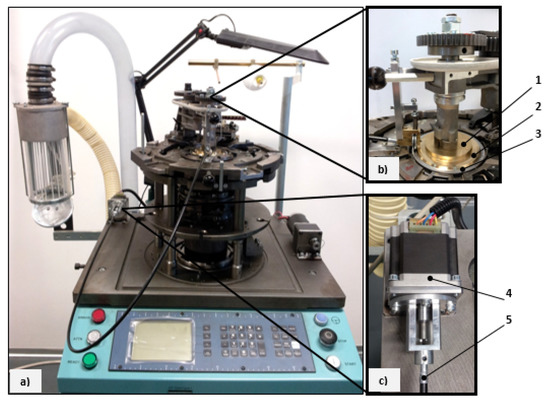
Figure 20.
Installation of the individual roller cutter drive system into the Ange 18.1 small diameter knitting machine and detailed display of the basic nodes of the individual roller cutter drive system.
The installation of the main part of the system (see Figure 20b) consisted of fitting a part of the dial 1 with a modified supporting flange 2 and a lower pan to form a bearing for the roller cutter 3. The test cutter had the same internal and external diameter and thickness defining its functional surfaces for proper placement in the bearing in the dial as a real roller cutter. Figure 20c shows a detailed view of the drive 4 and its used accessories needed to connect the flexible shaft 5.
The aim of the measurement was to verify the function of the designed individual drive system of the roller cutter at maximum velocity and the suitability of the drive used. The 103H7123-1710 stepping motor (Sanyo Denki, Tokyo, Japan) was selected to drive the cutter due to the assumption of power sufficiency and good speed control. The motor was controlled using the stepping motor drive box NDC69A (R.T.A., Düsseldorf, Germany), which is equipped with a built-in oscillator. It therefore does not require an external clock signal to determine the velocity for the constant velocity running function. The drive can then only be controlled with a start/stop signal. The driver furthermore provides start-up functions, and the drive current can also be adjusted. Another function is the automatic reduction of the drive current when stopping.
The time course of the voltage from the sidewall was recorded by the measuring control panel (HBM) and converted to the current value, see Figure 21. The outputs from the measurement of electrical values of the individual roller cutter drive system are presented in Table 3. Practical verification of the aforementioned design solution revealed that the roller cutter can move independently within the range of normal working velocities (0–320 min−1) of the considered knitting machine independently of the cylinder and the dial.
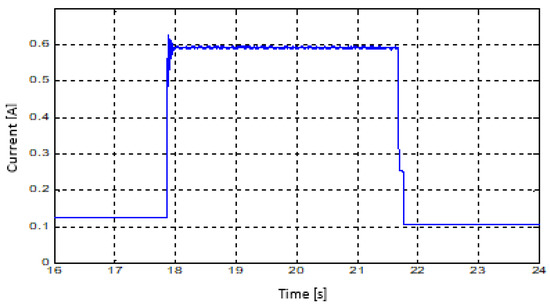
Figure 21.
Current course measurement.
Table 3.
Outputs from the measurement of the individual cutting disc drive system.
5. Conclusions
In the context of the production of classic stocking and sock goods, knitting is divided in practice into two modes. The first involves knitting the heel or toe of the sock, and the second generally involves making tubular knitted fabric. The first mode was subjected to a dynamic analysis, as the system performs rotational reverse motion within the range of the cylinder movement 0–3/4 π. This movement method of the drive system is classified as the dynamically least favorable load case of the entire machine. For a better understanding of the dynamic behavior of the drive system in reverse motion, two mathematical models have been elaborated for the existing and for the (patented) modified structure that now includes use of controlled drives. Mathematical models were created in the Matlab-Simulink programming environment. The findings of the performed dynamic analysis of the existing drive structure indicate (a) a significant influence of plays, whereas shocks occur upon their delimitation, and (b) the accompanying influence of the moment of inertia.
As a rule, a linear acceleration course cannot be achieved in the true configuration of the drive system, especially in transition areas of movement intervals due to sudden changes occurring in these areas. In the modified structure of the drive system, a reduction was achieved in the moment of inertia and the targeted use of the cylinder, dial and roller cutter according to the technological process. These adjustments appeared in more favorable courses of torques and power consumption of the modified drive system in comparison with the existing system while using more suitable lift dependences.
The use of fewer elements in the modified drive system achieved a significant suppression of the impact of plays and a decrease in dynamic effects adversely affecting not only this system, but also the entire machine and the technology performed. Another monitored parameter was the load on the drives in the individual phases of system movement and determination of the courses of their power inputs, especially in the area of rotational reverse motion. Here, the reduction of moment of inertia in the modified drive system was most evident, which significantly affected the decrease in electricity consumption during the start-up and run-out of the drive system. There was a 10% decrease in total electricity consumption in the creation of one sock in the modified drive system compared to the current one. The value of real electricity consumption will be higher due to the exclusion of certain effects; see Section 2.
In the past, the design of an individual dial drive system has been addressed by various studies, but its movement was always tied to the movement of the roller cutter, which still did not provide efficient use of the drive system of small-diameter knitting machines. For this reason, a design has been elaborated of an individual drive system of the roller cutter. The design was conceived in such a way as to influence the other construction nodes of the knitting machine as little as possible with respect to the existing installation possibilities. The result of the design is a drive system structure capable of independently driving the roller cutter and can be used modularly with possible structural modifications on the existing knitting machines of the analyzed type. Changing the structure of the drive brings the possibility of simplifying the overall concept of the knitting machine. With a reduction of rotating elements, especially gears—which generate noise, vibrations, and reduce the efficiency of power transmission from the drive to the main individual operating elements (dial, roller cutter and needle cylinder) and increase the demands on installation space and maintenance of the machine—the possibility of a conceptually completely different machine is offered. In light of the obtained results, the new concept of the knitting machine would bring, above all, a more energy-saving solution with a lower noise level on operators. Another benefit can be gained in the individual and programmable control of the mentioned operating elements and the expansion of technological possibilities in terms of production knitted products.
Author Contributions
Conceptualization, J.S. and M.B.; methodology, J.S.; software, J.S. and M.B.; validation, M.B.; formal analysis, J.S. and M.B.; investigation, J.S. and M.B.; resources, O.B. data curation, M.B. and O.B.; writing—original draft preparation, J.S.; writing—review and editing, J.S.; visualization, M.B.; supervision, O.B.; project administration, J.S.; funding acquisition, J.S. All authors have read and agreed to the published version of the manuscript.
Funding
This research was funded by the Student Grant Competition of the Technical University of Liberec under the project No. SGS-2022-5046 and the Institutional Endowment for the Long Term Conceptual Development of Research Institutes, as provided by the Ministry of Education, Youth and Sports of the Czech Republic.
Institutional Review Board Statement
Not applicable.
Informed Consent Statement
Not applicable.
Data Availability Statement
The data presented in this study is available on request from the cor-responding author.
Conflicts of Interest
The authors declare no conflict of interest concerning the research, authorship and publication of this article.
References
- Kopal, J. Knitting, Stitch-Knitting and Stranding 1, 1st ed.; Technical University of Liberec: Liberec, Czech Republic, 2006; ISBN 80-7372-119-8. [Google Scholar]
- Kopal, J. Knitting, Stitch-Knitting and Stranding 2, 1st ed.; Technical University of Liberec: Liberec, Czech Republic, 2007; ISBN 978-80-7372-246-3. [Google Scholar]
- Abbas, A.; Asim, A.; Zahid, A.; Anas, S.; Basra, S.A.; Azam, Z. Development of Knitted Reinforced Structures with Self-Diagnostic Function for Composite Applications. J. Ind. Text. 2022, 51, 15280837221098438. [Google Scholar] [CrossRef]
- Ertekin, G. Analysis of Thermo-Physiological Comfort and Moisture Management Properties of Flat Knitted Spacer Fabrics. Tekst. Konfeksiyon 2017, 27, 241–250. [Google Scholar]
- Oglakcioglu, N. Design of Functional Knitted Fabrics for Medical Corsets with High Clothing Comfort Characteristics. J. Ind. Text. 2016, 45, 1009–1025. [Google Scholar] [CrossRef]
- Supuren, G.; Oglakcioglu, N.; Ozdil, N.; Marmarali, A. Moisture Management and Thermal Absorptivity Properties of Double-Face Knitted Fabrics. Text. Res. J. 2011, 81, 1320–1330. [Google Scholar] [CrossRef]
- Zhou, L.; Feng, X.; Du, Y.; Li, Y. Characterization of Liquid Moisture Transport Performance of Wool Knitted Fabrics. Text. Res. J. 2007, 77, 951–956. [Google Scholar] [CrossRef]
- Spencer, D.J. 12-Electronics in Knitting. In Knitting Technology, 3rd ed.; Spencer, D.J., Ed.; Woodhead Publishing Series in Textiles; Woodhead Publishing: Sawston, UK, 2001; pp. 134–144. ISBN 978-1-85573-333-6. [Google Scholar]
- Jindal, H.; Kaur, S. Robotics and Automation in Textile Industry. Int. J. Sci. Res. Sci. Eng. Technol. 2021, 8, 40–45. [Google Scholar] [CrossRef]
- Skřivánek, J.; Bílek, M. Dynamics of the Frame of Small-Diameter Knitting Machine. Dynamika ramy małośrednicowej maszyny dziewiarskiej. ACC J. 2010, 14, 1–7. [Google Scholar]
- Goch, G. Gear Metrology. CIRP Ann.-Manuf. Technol. 2003, 52, 659–695. [Google Scholar] [CrossRef]
- Ray, S.C. 7-Circular Weft Knitting Machine and Mechanism. In Fundamentals and Advances in Knitting Technology; Ray, S.C., Ed.; Woodhead Publishing: Delhi, India, 2012; pp. 69–85. ISBN 978-0-85709-108-6. [Google Scholar]
- Power, E.J. Chapter 12-Yarn to Fabric: Knitting. In Textiles and Fashion; Sinclair, R., Ed.; Woodhead Publishing Series in Textiles; Woodhead Publishing: Sawston, UK, 2015; pp. 289–305. ISBN 978-1-84569-931-4. [Google Scholar]
- Lucia, T. Consiglia: A Complete Guide to Machine Knitting; Hoakibooks S.L.: Barcelona, Spain, 2021; ISBN 84-17412-86-7. [Google Scholar]
- Subhankar, M.; Sohel, R.; Pintu, P.; Kunal, S. Advanced Knitting Technology|Libristo-Czech Republic; Elsevier Books: Amsterdam, The Netherlands, 2021; ISBN 978-0-323-85534-1. [Google Scholar]
- Paprocki, M.; Erwiński, K. Synchronization of Electrical Drives via EtherCAT Fieldbus Communication Modules. Energies 2022, 15, 604. [Google Scholar] [CrossRef]
- BILEK, M.; Skřivánek, J.; Kopal, J.; Váša, P. Okrouhlý Pletací Stroj, No. 303578; Czech Pattent Office: Prague, Czech Republic, 2012. [Google Scholar]
- Zaw, A.K.; Myat, A.M.; Thandar, M.; Htun, Y.M.; Aung, T.H.; Tun, K.M.; Han, Z.M. Assessment of Noise Exposure and Hearing Loss Among Workers in Textile Mill (Thamine), Myanmar: A Cross-Sectional Study. Saf. Health Work. 2020, 11, 199–206. [Google Scholar] [CrossRef]
- Dini, P.; Saponara, S. Design of an Observer-Based Architecture and Non-Linear Control Algorithm for Cogging Torque Reduction in Synchronous Motors. Energies 2020, 13, 2077. [Google Scholar] [CrossRef]
- Zheng, B.; Jiang, G.; Dong, Z.; Liu, H. Design of Warp Knitting Electronic Shogging System Based on Mixed-Velocity Planning Curve. Text. Res. J. 2021, 91, 1594–1608. [Google Scholar] [CrossRef]
- Intellectual Property of Uniplet Třebíč a.s. Technical Documentation of the Small-Diameter Knitting Machine Series Ange 18.1; Intellectual Property of Uniplet Třebíč a.s.: Třebíčv, Czech Republic, 2014. [Google Scholar]
- Negrean, I.; Crișan, A.-V.; Vlase, S. A New Approach in Analytical Dynamics of Mechanical Systems. Symmetry 2020, 12, 95. [Google Scholar] [CrossRef]
- Negrean, I.; Crișan, A.; Șerdean, F.; Vlase, S. New Formulations on Kinetic Energy and Acceleration Energies in Applied Mechanics of Systems. Symmetry 2022, 14, 896. [Google Scholar] [CrossRef]
- Skřivánek, J.; Bílek, M. Analysis of Dynamic Model of the Drive of Small Diameter Knitting Machines Ange 18.1. Analiza modelu dynamicznego napędu małośrednicowej maszyny dziewiarskiej Ange 18.1. ACC J. 2011, 15, 1–8. [Google Scholar]
- Mrázek, J. Theoretical Analysis of Dynamics of Four-Bar Beat-up Mechanism of a Loom. Mech. Mach. Theory 1992, 27, 331–341. [Google Scholar] [CrossRef]
- Skřivánek, J.; Bílek, M.; Kašpárek, M. Control Optimisation of the New Drive of Small Diameter Knitting Machines. Autex Res. J. 2016, 17, 1–5. [Google Scholar] [CrossRef][Green Version]
- Alam, S.N.; Islam, S.; Patel, S.K. Advanced Guide to MATLAB: Practical Examples in Science and Engineering; IK International Publishing House Pvt. Ltd.: Delhi, India, 2015; ISBN 978-93-84588-35-9. [Google Scholar]
- Hairer, E.; Nørsett, S.; Wanner, G. Solving Ordinary Differential Equations I, Nonstiff Problems; Springer: Berlin, Germany, 1993; ISBN 978-3-540-56670-0. [Google Scholar]
- Rotational Kinetic Energy—An Overview|ScienceDirect Topics. Available online: https://www.sciencedirect.com/topics/engineering/rotational-kinetic-energy (accessed on 3 June 2022).


Publisher’s Note: MDPI stays neutral with regard to jurisdictional claims in published maps and institutional affiliations. |
© 2022 by the authors. Licensee MDPI, Basel, Switzerland. This article is an open access article distributed under the terms and conditions of the Creative Commons Attribution (CC BY) license (https://creativecommons.org/licenses/by/4.0/).