Article

Machining of Wood Plastic Composite Using AWJ Technology with Controlled Output Quality

1
Faculty of Manufacturing Technologies of Technical University of Košice with Seat in Prešov, 080 01 Prešov, Slovakia
2
Faculty of Humanities and Natural Science, University of Prešov, 080 01 Prešov, Slovakia
*
Author to whom correspondence should be addressed.
Machines 2022, 10(7), 566; https://doi.org/10.3390/machines10070566
Submission received: 15 June 2022 / Revised: 11 July 2022 / Accepted: 13 July 2022 / Published: 14 July 2022
(This article belongs to the Special Issue Advances in Computer-Aided Technology)

Abstract

:
The paper deals with the application of abrasive water-jet cutting to composite material containing natural reinforcement—wood plastic composite. The specimens were cut through the application of four flows of different abrasive mass: 150, 200, 250, and 300 g·min−1, respectively, and under different traverse speeds required to achieve the (expected) quality level Q1–Q5 (according to the SN 214001: 2010 standard). The output quality of Q1–Q5 was set in the CNC cutting programs and the real traverse speed values were calculated by machine control system according to change in the flow of the abrasive mass. The quality of surface topography was assessed using a tester (contact roughness) and an Inspectis digital zoom microscope. The results of topography–surface roughness parameters Ra presented here are compared with the values normalized for individual samples sets. The applied technology, i.e., the AWJ, eliminated the problem of tool wear and adhesion of the thermoplastic matrix to tool surfaces (compared to standard machining).

1. Introduction

Since the 1990s, the professional literature and technologists have been paying increased attention to the application of natural fiber/particle reinforcement materials (lignocellulosic, mineral, and animal) in the automotive, construction, and flooring industries [1,2,3,4]. Natural reinforcements can replace synthetic/glass fibers in plastic matrices (PE, PVC, PP, and epoxy) based on three attributes:
  • Reduced input costs, shorter production cycles of composite materials, and lower weight of materials;
  • Identical/similar mechanical properties compared to components reinforced with glass fiber, good dimensional stability and soundproofing;
  • Recyclability of primary raw materials, non-toxicity, and CO2 neutrality (carbon neutrality means achieving a balance between carbon emissions and their absorption from the atmosphere into carbon traps) [5,6,7,8].
In the commercial processing of WPC materials, wood flours with various types of wood, softwood and hardwood, are applied and, alternately, also plant fibers (lignocellulosic fibers) [9]. Many scientific studies point to the possibilities of using waste from the agricultural industry as an alternative to wood flour and achieving similar properties of the WPC product. More than 95% of WPC products originating in China are made from agricultural waste [10,11,12,13,14,15]. The choice of matrix material determines the processing temperature. Reinforcements consist of organic materials (cellulose, hemicellulose, and lignin) susceptible to thermal degradation upon reaching the boundary temperature of about 200 °C [16]. Based on their melting point, the following materials are suitable: polyethylene, polypropylene, polyvinylchloride, or polystyrene. Studies are currently underway to verify the application of PMMA or Nylon 6 as matrices of WPC products [17,18,19,20,21]. To improve the mechanical properties of the final product, to provide chemical bonding, and to achieve a simpler process of mixing components (rheological properties), additives are applied in different percentages (Figure 1: components of wood-filled plastics) [16,22,23,24,25,26,27,28,29,30].
The main conventional processes used in WPC manufacturing are: extrusion process, injection molding, compression molding, calendaring, laser sintering, and fused laser modeling [17,34,35,36]. Technologies applied in the products manufacturing in individual industries are presented in Table 1 (++ very important and gaining rapid traction, or + important and on the rise, or 0 less important and small, respectively). The WPC raw materials should undergo preprocessing treatments to enhance the interfacial bonding between the wood flour and the polymer matrix [37].
The earliest developments of WPCs date back to the 1970s, with Gruppo Ovattifici Riuniti producing a product named “Woodstock” for Fiat cars in 1972 (composite material made of plastic matrix and wood filling in the ratio of 50:50) and Sonesson AB producing a PVC/wood-flour composite for use as flooring tiles in 1973 [38,39,40,41]. In 1991, the first conference on the mentioned composite materials was held, with participation of 50 researchers and WPC manufacturers themselves. At present, demand for WPC products is expected to increase by 14% year on year in European countries. Research focusing on improving the compatibility of components, reduction in their density and price, and application of biopolymers for matrices is becoming ever more important [39].
From the machinability point of view, WPC materials can be characterized as easily machinable (the authors Wilkowski et al. made the comparison with standard MDF boards with their determined machinability index) [42]. Many current authors deal with classic machining technologies, which are oriented on selection of tool geometry/material, study of suitable conditions of machining technologies in relation to the emerging surface quality, the emergence of cutting forces during machining, etc. [43,44,45,46,47,48,49,50,51]. However, they encounter a fundamental problem—melting the thermoplastic matrix and adhesion to the tool surfaces during the engagement (functional surfaces). An option for WPC machining is the application of water jet/abrasive water jet technology. There are a number of studies dealing with the machining of a wide range of materials (including different types of woods) [52,53,54]. However, only a small percentage of publications are available in the given area of interest (machining of WPC by AWJ/WJ); in the year 2012, the study of wood slabs was conducted by Hutyrová et al., examining the influence of a selected technological parameter: traverse speed and the MESH abrasive applied on micro-geometric and macro-geometric surface characteristics (basic surface roughness parameters Ra—arithmetic mean deviation of the profile and Rz—maximum height of the profile were determined in accordance with ISO 4287 and the parameters of the emerging thread of the turned surface). The best surfaces were achieved at lower traverse speed: 40 mm·min−1 [55]. In 2022, Boopathi et al. dealt with the influence of process parameters (traverse speed and water jet pressure) and the makeup of the composite in terms of the percentage representation of its individual components on surface roughness and kerf angle using the Taguchi method. It was observed that kerf angle and surface roughness were greatly impacted by the percentage of neem wood saw powder, table traveling speed, and water-jet pressure [56].
As the number of publications in the field is scanty, the article focuses on the influence of variable factors of selected technological parameters on the surface topography of composite materials containing natural reinforcement after cutting by a hydro abrasive water jet. The controlled parameter is the final surface roughness (Q1–Q5). Currently, the Swiss standard SN 214001: 2010 (the standard applies to materials up to a thickness of 300 mm) defining individual quality levels is in force for assessing surface topography by hydro abrasive water jet. The mentioned standard is applicable to materials suitable for AWJ cutting. Based on the determined measured parameters, the machined surface is divided into five levels (Q5 up to Q1), while the cut quality Q1 is defined as the lowest and the cut quality Q5 as the highest [57].

2. Materials and Methods

The experiment used wood–plastic composite material (beam with a rectangular cross-section, dimensions 40 × 60 × 150 mm), consisting of a polyethylene matrix reinforced with wood fibers (ratio 25/75 vol.%). The material contains cracks at the interface: wood versus plastic; wood fibers/particles copy the flow of the extruded matrix (Figure 2). Mechanical properties were determined in the laboratories of VÚHŽ-Dobrá, in accordance with relevant ISO standards (tensile test/triaxial bending test). Average values were Rm = 9.5 MPa, A = ca 3%, Z = 0.9%, flexural strength 16.8 MPa, and deformation work 0.7 mJ (statistically verified values). Density of extruded profile was between 500 and 700 kg·m−3 (at the temperature of 20 °C), and swelling after water storage was ≤7.0% (volume weight). Applications of WPC materials: construction (exterior cladding), flooring and furniture industry (floor coverings), and automotive/shipbuilding industry (dashboards, trunk bottoms, etc.).
WPC materials represent an ecological alternative (in relation to wood products) with a positive contribution to sustainable natural resources (forest areas). The ever-increasing environmental pressure, new ways of using natural-based composite materials, as well as technical innovations are leading manufacturers to apply them. Goal: to reduce the consumption of costly, nonrecyclable types of reinforcement, e.g., glass fibers.

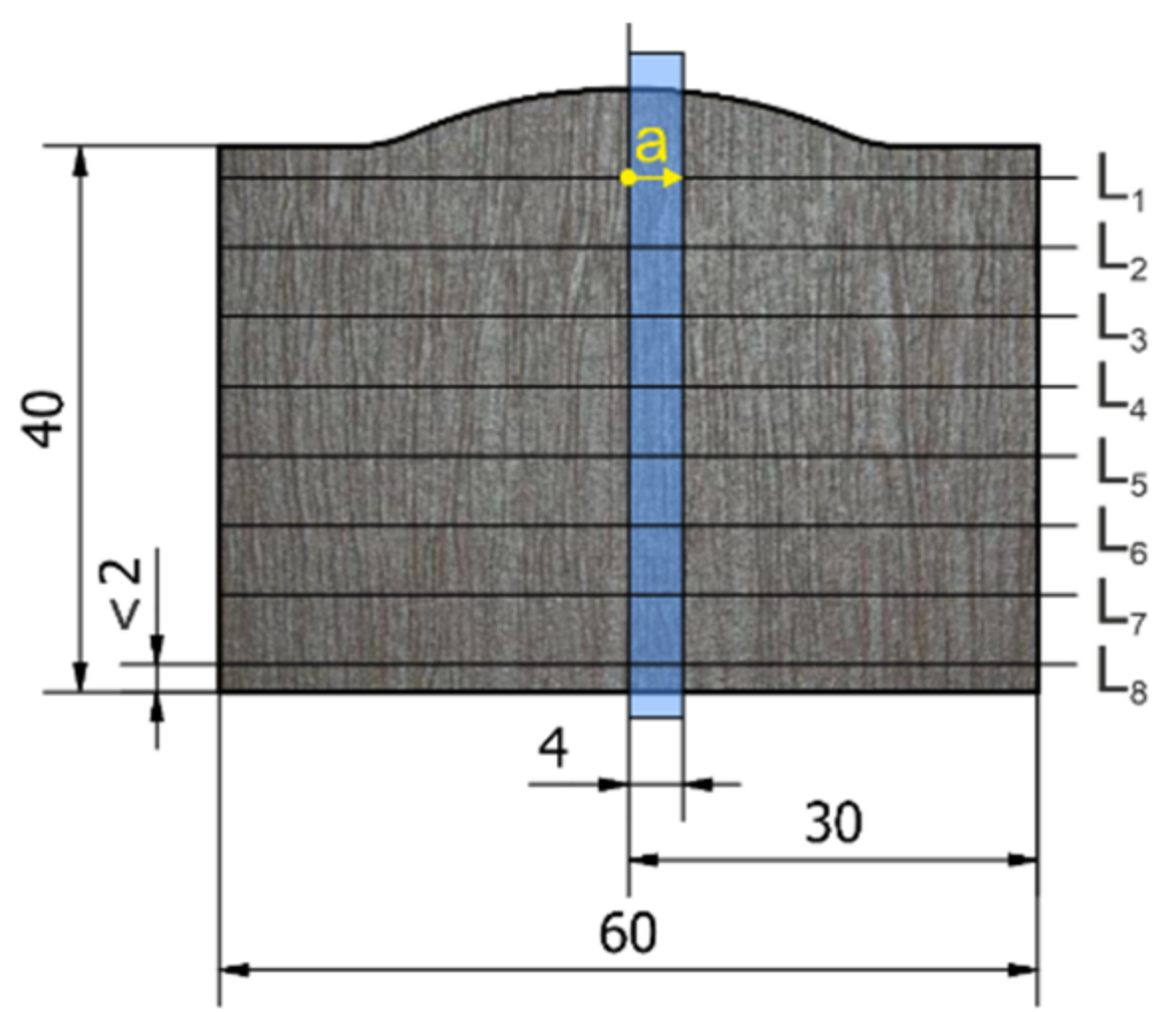
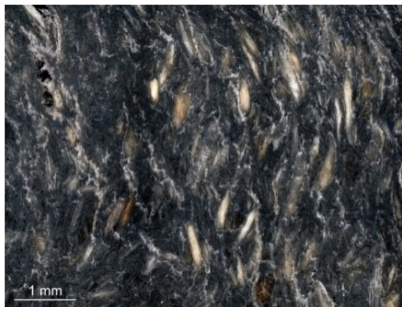
2.1. Sample Preparation and Analysis of Experimental Surface Topography Measurement

The measurement was performed on 20 samples (5 sets of samples—Figure 3) divided by different sliding speeds of the cutting head (sliding speeds of the cutting head were set based on the required cut quality according to SN 214001: 2010, see Table 2) with different abrasive flow (variable factors: head feed rate vf/abrasive mass flow ma). To study the influence of process parameters on the quality of the machined surface during AWJ cutting, a conventional device for cutting flat materials using Water Jet 3015 RT-3D was used. The required water pressure of 400 MPa was generated by the PTV JETS—3.8/60 Classic pump. Australian Garnet with MESH 80 was used as the abrasive material. The angle of inclination of the abrasive head = 90°, the diameter of the water nozzle d0 = 0.3 mm, the diameter of the focusing tube df = 0.9 mm, and the standoff distance of the nozzle was 4 mm.

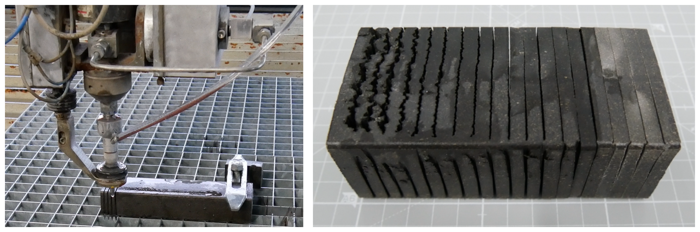
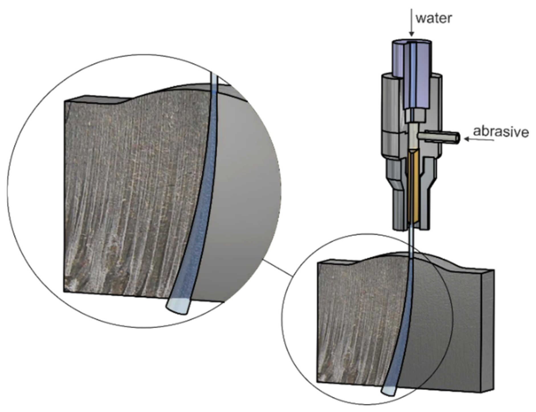
2.2. Topography of Horizontal Areas of the Material Surface Created by Abrasive Cutting (Experimental Setup)

Currently in force, the Swiss standard SN 214001: 2010 applies to materials up to a thickness of 300 mm, defining individual quality levels for the evaluation of surface topography by hydro abrasive current. Based on the set measured parameters, the machined surface is divided into 5 levels (Q1–Q5), while the cut quality Q1 is defined as the lowest and the cut quality Q5 as the highest. The corresponding values of the parameter Ra defined by the standard are given in Table 3.
Parameters of surface roughness (Ra and Rz) were determined by the contact roughness tester: MITUTOYO at the Faculty of Manufacturing Technologies seated in Prešov. The standard EN ISO 4287: 1997 is adopted for the quantitative evaluation of surface roughness [58]. Surface roughness is a geometric property and there are no direct methods for its assessment. Suitable characteristics and parameters are taken into account, which are considered to constitute surface roughness criteria. The most common evaluation criterion is the mean arithmetic deviation of the surface irregularities Ra (or the greatest height of the profile Rz) evaluated with respect to the baseline in the base length lr. In order to identify and analyze factors affecting the surface topography, measurements were performed stepwise through the horizontal area of the sample according to Figure 4 (in relation to the shape of the profile, produced by extrusion, the first measured section was placed outside the rounded area of the sample). Line L8 is located 2 mm from the bottom edge of the profile (Figure 4). Values shown in the graphical dependences are averages from 9 repeated measurements (evaluated characteristic: Ra). The Grubbs test with a probability of p = 95% was applied to exclude values subjected to gross error.

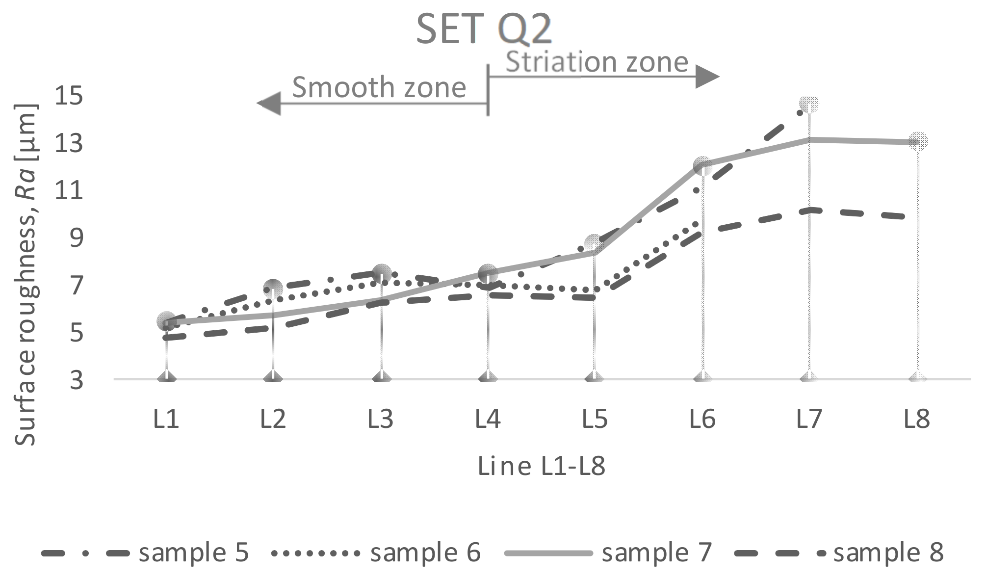
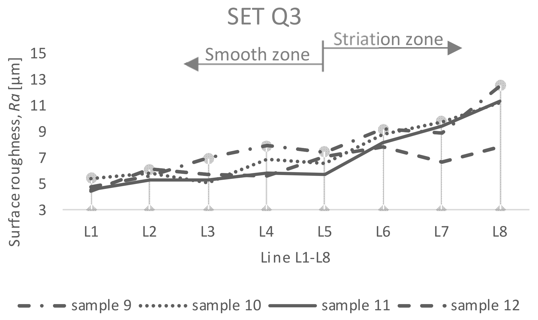
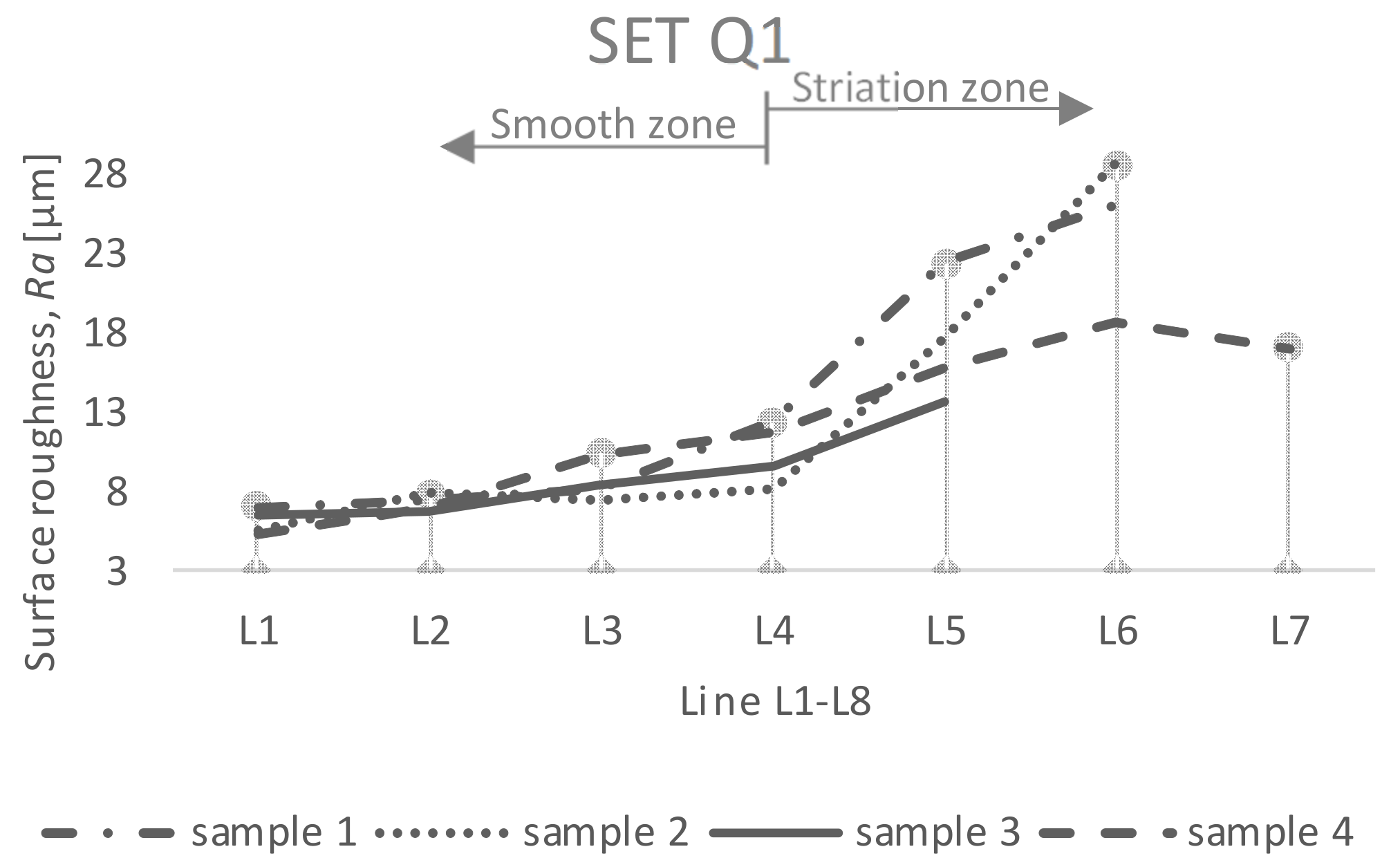
3. Results and Discussion

After the performed experimental measurements and processing of the measured parameters, information was obtained about the height inequalities of the surface topography created under the changing experimental conditions. In relation to the controlled result parameter QX (categorization of the resulting surface Q1 to Q5 with varying abrasive mass flow and feed rate), each set must be assessed separately. Measurement was conducted nine times for each measuring line; subsequently, graphical dependences and tables show arithmetical values for individual lines.
Set Q1 (Figure 5): the surfaces shown consist of two distinctive zones: smooth and striation zones. In the case of four evaluated samples, it is not possible to perform measurements in all defined lines L1 to L8, where, in samples 1 and 2, missed measurements are in lines L7 and L8; in sample 3, missed measurements are in lines L6 to L8; and, in sample 4, a missed measurement is in line L8. The surface of the mentioned lines is defined as too rough. The values of the parameter Ra have a significantly increasing tendency from the line L4 (about half of the cut made). In the case of samples of the Q1 set, there was no complete division and the samples had to be separated manually (see right corner of sample 1—phenomena is caused by jet lag in the direction of traverse speed, Table 3). As the depth of the cut increases, the values of the Ra parameters increase. After passing line L4, increased deformation in the lower part of the workpiece is visible in all samples—formation of defects belonging to a macroscopic (scratches and grooves) group, Table 3. In relation to the inhomogeneous nature of the material, samples 1 and 2 (in addition to significant traces of lagging water flow) also contain traces/grooves/deformities. The mechanism of material removal using the AWJ is characterized as a micro-erosion process. With the increasing thickness of machined material and increased traverse speed, significant traces in the material can be observed, caused by kinetic energy loss.
Set Q2 (Figure 6): the surfaces shown also consist of two distinctive zones: smooth and striation zones. In the case of the two evaluated samples, it is not possible to perform measurements in all eight lines under assessment (sample 5: missed measurements in lines L7, L8; sample 6: missed measurement in line L8). The highest value of the Ra parameter achieved was recorded in the case of sample 5, namely, of 14.64 µm in line L7.
In the case of sets Q3 and Q4 (Figure 7 and Figure 8), it was possible to measure the assessed parameter Ra in all selected lines. Smooth and striation zones are defined by line L5. For samples 9 to 12, the highest Ra values were recorded in the last line L8 (located 2 mm from the bottom edge of the sample).
In the case of set Q5 (Figure 9), the values of the parameter Ra for all samples were in the range from 3.93 to 7.59 µm (from sample 17 to sample 20). The surface is relatively smooth (compared to other sets). For comparison with the value specified by the standard, we present the table below. Only in the case of six divided areas (samples 7, 8, 10, 11, 12, and 15), the Ra values measured in line L8 comply with the relevant Q-level. The set Q3 contains the most samples corresponding to the prescribed value.
Pictures in Table 3 were observed on the Inspectis digital zoom microscope (samples marked 1, 5, 9, 13, and 17). The individual samples show a visible difference in the quality of the cut trace after the AWJ machining under different technological conditions. Samples marked 9, 13, and 17 showed lowest “ripple” as opposed to samples marked 1 and 5. Samples 1 and 5 show the resistance that the material exerts on the nozzle transverse trace. The greatest resistance can be observed in the sample marked no. 1. In this sample 1, small cavitation points of wood fillings are also observed, which can be observed in smaller evaluated samples.

4. Conclusions

The applied cutting technology by means of the AWJ eliminated the problem of tool wear and adhesion of the thermoplastic component to the tool surfaces in the engagement (so-called functional surfaces). The resulting split areas of sets Q1–Q5 can be divided into two zones: smooth and striation zones, depending on the specific sample of each of the five sets. Based on the ISO 4287 standard, the surface roughness parameter Ra, mean arithmetic deviation of the profile (assessed in eight lines of machined surfaces), was assessed. In the case of six samples, sample 1 to sample 4, sample 5, and sample 8, measurements in the specified lines could not be performed (in the lower lines, the surface was defined as too rough). The SN 214001: 2010 standard was applied for the qualitative evaluation of the machined surface. When compared with the prescribed value of Ra (determined by the standard according to the quality level Q1 to Q5), it is possible to say that the most compliant with the standard are values of Ra of the Q3 set (samples: 10, 11, and 12). The Ra values achieved for samples 10 to 12 are lower than the value set by the standard (standard Ra value = 12.5 µm). However, it remains questionable whether the standard and the assignment of quality levels Q1–Q5 are satisfactory for all types of assessed materials. The aim of the present contribution was to verify whether it is possible to achieve the surface quality prescribed by the standard on heterogeneous WPC materials through a controlled AWJ cutting process.

Author Contributions

Conceptualization, Z.M.; methodology, Z.M.; software, F.B. and R.V.; investigation, Z.M. and D.M.; resources, F.B.; data curation, Z.M.; writing—original draft preparation, F.B. and Z.M.; writing—review and editing, F.B.; visualization, J.L.; supervision, V.S. All authors have read and agreed to the published version of the manuscript.

Funding

This research was funded by APVV-20-0514 and KEGA no. 032TUKE-04/2021.

Data Availability Statement

Not applicable.

Acknowledgments

This work was supported by the Slovak Research and Development Agency under the contract No. APVV-20-0514 (Research of the influence of technological parameters of abrasive water jet machining on the surface integrity of tool steels) and project KEGA no. 032TUKE-4/2021—Transfer and implementation of knowledge in the field of energy beam technologies into study programs of technical secondary schools supporting dual education.

Conflicts of Interest

The authors declare no conflict of interest. The founding sponsors had no role in the design of the study; in the collection, analyses, or interpretation of data; in the writing of the manuscript; or in the decision to publish the results.

References

  1. Sanjay, M.R.; Suchart, S.; Parameswaranpillai, J.; Jawaid, M.; Ozbakkaloglu, T. Lignocellulosic fiber reinforced composites: Progress, performance, properties, applications, and future perspectives. Polym. Compos. 2021, 43, 645–691. [Google Scholar]
  2. Puglia, D.; Biagiotti, J.; Kenny, J.M. Applications of Natural Reinforcements in Composite Materials for Automotive Industry. J. Nat. Fibers 2005, 1, 23–65. [Google Scholar] [CrossRef]
  3. Ferreira, F.V.; Pinheiro, I.F.; de Souza, S.F.; Mei, L.H.I.; Lona, L.M.F. Polymer Composites Reinforced with Natural Fibers and Nanocellulose in the Automotive Industry: A short Review. J. Compos. Sci. 2019, 3, 51. [Google Scholar] [CrossRef] [Green Version]
  4. Khalid, M.Y.; Rashid, A.A.; Arif, Z.U.; Ahmed, W.; Arshad, H.; Zaidi A., A. Natural fiber reinforced composites: Sustainable materials for emerging applications. RINENG 2021, 13, 100263. [Google Scholar] [CrossRef]
  5. Dilpreet, S.B.; Bhattacharjee, S. Current Progress, trends and Challenges in the Application of Biofiber Composites by Automotive Industry. J. Nat. Fibers 2016, 13, 660–669. [Google Scholar]
  6. Azman, A.; Asyraf, M.; Khalina, A.; Petru, M.; Ruzaidi, C.M.; Sapuan, S.M.; Nik, W.B.W.; Ishak, M.R.; Ilyas, R.A.; Suriani, M.J. Natural Fiber Reinforced Composite Material for Product Design: A short Review. Polymers 2021, 13, 1917. [Google Scholar] [CrossRef]
  7. Lotfi, A.; Huaizhong, L.; Dao, D.V.; Prusty, G. Natural fiber-reinforced composites: A review on material, manufacturing and machinability. J. Thermoplast. Compos. Mater. 2019, 34, 238–284. [Google Scholar] [CrossRef]
  8. Campilho, R.D.S.G. Natural Fiber Composites; Taylor & Francis Group: Boca Raton, FL, USA, 2016; pp. 16–22. [Google Scholar]
  9. Fabiyi, J.S.; McDonald, A.G. Effect of wood species on property and weathering performance of wood plastic composites. Compos. Part A Appl. Sci. Manuf. 2010, 41, 1434–1440. [Google Scholar] [CrossRef]
  10. Nourbakhsh, A.; Ashori, A. Wood plastic composite from agro-waste materials: Analysis of mechanical properties. Bioresour. Technol. 2010, 101, 2525–2528. [Google Scholar] [CrossRef]
  11. Abba, H.A.; Nur, I.Z.; Salit, S.M. Review of agro waste plastic composites production. J. Met. Mater. Miner. 2013, 1, 271–279. [Google Scholar] [CrossRef] [Green Version]
  12. Chen, J.; Teng, Z.; Wu, J. Recycling of waste FRP and corn straw in wood plastic composite. Polym. Compos. 2017, 38, 2140–2145. [Google Scholar] [CrossRef]
  13. Chun, K.S.; Fahamy, N.M.Y.; Yeng, H.Y.; Choo, H.L.; Ming, P.M.; Tshai, K.Y. Wood plastic composites made from corn husk fiber and recycled polystyrene foam. J. Eng. Sci. Technol. Rev. 2018, 13, 3445–3456. [Google Scholar]
  14. Rahman, M.R.; Bakri, M.K.B. Recycled Plastic Composites, 1st ed.; Elsevier: Amsterdam, The Netherlands, 2022; pp. 21–24. [Google Scholar]
  15. Binhussain, M.A.; El-Tomsy, M.M. Palm leave and plastic waste wood composite for out-door structures. Constr. Build. Mater. 2013, 47, 1431–1435. [Google Scholar] [CrossRef] [Green Version]
  16. Klyosov, A.A. Wood-Plastic Composites, 1st ed.; John Wiley & Sons, Inc.: Hoboken, NJ, USA, 2007; pp. 50–51. [Google Scholar]
  17. Gardner, D.J.; Han, Y.; Wang, L. Wood-Plastic composite technology. Curr. For. Rep. 2015, 1, 139–150. [Google Scholar] [CrossRef] [Green Version]
  18. Vovk, M.; Sernek, M. Aluminium Trihydrate-filled Poly(methyl methacrylate) (PMMA/ATH) Waste Powder Utilization in Wood-plastic Composite Boards Bonded by MUF Resin. Bioresources 2020, 15, 3252–3269. [Google Scholar] [CrossRef]
  19. Laming, P.B. Some anatomical and physical aspects of wood-plastic (pMMA) combination of spruce. Leiden Bot. Ser. 1976, 3, 266–280. [Google Scholar]
  20. Rowell, R.M. Wood Chemistry and Wood Composites, 1st ed.; Taylor & Francis: Boca Raton, FL, USA, 2005; pp. 366–377. [Google Scholar]
  21. Liu, H.Z.; Yao, F.; Xu, Y.J.; Wu, Q.L. A novel wood flour-filled composite based on microfibrillar high-density polyethylene (HDPE)/Nylo-6 blends. Bioresource Technol. 2010, 101, 3295–3297. [Google Scholar] [CrossRef]
  22. Niska, K.O.; Sain, M. Wood-Polymer Composites, 1st ed.; Woodhead Publishing Limited: Cambridge, UK, 2008; pp. 23–40. [Google Scholar]
  23. Najafi, S.K. Use of recycled plastics in wood plastic composites—A review. J. Waste Manag. 2013, 33, 1898–1905. [Google Scholar] [CrossRef]
  24. Harper, D.; Wolcot, M. Interaction between coupling agents and lubricants in wood-polypropylene composites. Compos. Part A Appl. Sci. Manuf. 2010, 101, 3295–3297. [Google Scholar] [CrossRef]
  25. Bhaskar, K.; Jayabalakrishnan, D.; Kumar, M.V.; Sendilvelan, S.; Prabhahar, M. Analysis on mechanical properties of wood plastic composite. Mater. Today Proc. 2022, 61, 5886–5891. [Google Scholar] [CrossRef]
  26. Markarin, J. Additive developments aid growth in wood-plastic composites. Plast. Addit. Compd. 2017, 25, 361–367. [Google Scholar] [CrossRef]
  27. Schirp, A.; Ibach, R.E.; Pendleton, D.E.; Wolcott, M.P. Biological degradation of wood-plastic composites (WPC) and strategies for improving the resistance of WPC against biological decay. In Proceedings of the 229th National Meeting of the American-Chemical Society, San Diego, CA, USA, 13–17 March 2005. [Google Scholar]
  28. Khamedi, R.; Hajikhani, M.; Ahmaditabar, K. Investigation of maleic anhydride effect on wood plastic composites behavior. J. Compos. Mater. 2018, 53, 1955–1962. [Google Scholar] [CrossRef]
  29. Huuhilo, T.; Martikka, O.; Butylina, S.; Kärki, T. Impact of Mineral Fillers to the Moisture Resistance of Wood-Plastic Composites. Balt. For. 2010, 16, 126–131. [Google Scholar]
  30. Dai, L.; Wang, X.; Zhang, J.; Wang, F.; Ou, R.; Song, Y. Effect of lubricants on the rheological and mechanical properties of wood flour/polypropylene composites. J. Appl. Polym. Sci. 2019, 136, 47667. [Google Scholar] [CrossRef]
  31. Available online: https://www.pawanplastics.com/orange-dana-3850200.html (accessed on 15 June 2022).
  32. Available online: https://www.dreamstime.com/royalty-free-stock-photos-wood-shavings-image38097888 (accessed on 15 June 2022).
  33. Available online: https://balticday.com (accessed on 15 June 2022).
  34. Benoit, N.; Rodrigue, D. Extrusion-calendering of foamed and unfoamed wood/plastic composites. In Proceedings of the Annual Technical Conference—ANTEC, Orlando, FL, USA, 2–4 April 2012. [Google Scholar]
  35. Gacitua, W.; Bahr, D.; Wolcott, M. Damage of the cell wall during extrusion and injection molding of wood plastic composites. Compos. Part A Appl. Sci. Manuf. 2010, 41, 1454–1460. [Google Scholar] [CrossRef] [Green Version]
  36. Wlsheik, A.H.; Palchal, H.; Shanmugan, S.; Muthuramalingam, T.; El-Kassas, A.M.; Ramesh, B. Recent progresses in wood-plastic composites: Pre-processing treatments, manufacturing, techniques, recyclability and eco-friendly assessment. Clean. Eng. Technol. 2022, 8, 100450. [Google Scholar]
  37. Imken, A.A.P.; Brischke, C.; Kögel, S.; Krause, K.C.; Mai, C. Resistance of different wood-based materials against mould fungi: Comparison of methods. Eur. J. Wood Wood Prod. 2020, 78, 661–671. [Google Scholar] [CrossRef]
  38. Jones, J.; Brischke, K. Performance of Bio-Based Building Materials; Woodhead Publishing Limited: Cambridge, UK, 2017; pp. 21–96. [Google Scholar]
  39. Ansel, M.P. Wood Composites; Woodhead Publishing Limited: Cambridge, UK, 2015. [Google Scholar]
  40. Clemons, C.M. Woodfiber-plastic composites in the United States—History and current and future markets. In Proceedings of the 3rd International Wood and Natural Fibre Composites Symposium, Kassel, Germany, 19–20 September 2000. [Google Scholar]
  41. Zefang, X.; Linbo, Z.; Yanjun, X.; Qingwen, W. Review for development of wood Plastic Composites. J. Northeast For. Univ. 2003, 31, 39–41. [Google Scholar]
  42. Wilkowski, J.; Borysiuk, P.; Górski, J.; Czarniak, P. Analysis of relative machinability indexes of wood particle boards bonded with waste thermoplastic. Drewno 2013, 56, 139–144. [Google Scholar]
  43. Hutyrová, Z.; Harničárová, M.; Zajac, J.; Valíček, J.; Mihok, J. Experimental study of surface roughness of wood plastic composite after turning. Adv. Mater. Res. 2013, 856, 108–112. [Google Scholar] [CrossRef]
  44. Wei, W.; Yingli, L.; Li, Y.; Xu, Y. Tool wear during high-speed milling of Wood-plastic composites. Bioresources 2019, 14, 8678–8688. [Google Scholar]
  45. Zhu, Z.; Buck, D.; Wang, J.; Wu, Z.; Xu, W.; Guo, X. Machinability of different Wood-plastic composites during peripheral milling. Materials 2022, 15, 1303. [Google Scholar] [CrossRef]
  46. Guo, X.; Ekevad, M.; Marklund, B.; Li, R.; Cao, P.; Grönlund, A. Cutting forces and chip morphology during wood plastic composite orthogonal cutting. Bioresources 2014, 9, 2090–2106. [Google Scholar] [CrossRef] [Green Version]
  47. Buehlmann, U.; Saloni, D.; Lemaster, R.L. Wood fiber-plastic composites: Machining and surface quality. In Proceedings of the 15th International Wood Machining Seminar, Aaheim, CA, USA, 30 July–1 August 2001. [Google Scholar]
  48. Pritchard, G. Two technologies merge: Wood plastic composites. Plast. Addit. Compd. 2004, 6, 18–21. [Google Scholar] [CrossRef]
  49. Rajmohan, T.; Vinayagamoorthy, R.; Mohan, K. Review on effect machining parameters on performance of natural-fibre reinforced composites (NFRCs). J. Thermoplast. Compos. Mater. 2018, 32, 1282–1302. [Google Scholar] [CrossRef]
  50. Vinayagamoorthy, R.; Rajmohan, T. Machining and its challenges on bio-fibre reinforced plastics: A review. J. Reinf. Plast. Compos. 2018, 37, 1037–1050. [Google Scholar] [CrossRef]
  51. Svetlik, J.; Baron, P.; Dobránsky, J.; Kočiško, M. Implementation of computer system for support of technological preparation of production for technologies of surface processing. In Proceedings of the 13th International Conference on Industrial, Service and Humanoid Robotics, Strbské Pleso, Slovakia, 15–17 May 2014. [Google Scholar]
  52. Pelit, H.; Yaman, O. Influence of processing parameters on the surface roughness of solid wood cut by abrasive water jet. Bioresources 2020, 15, 6135–6148. [Google Scholar] [CrossRef]
  53. Haskish, M. Characteristics of surfaces machined with abrasive-waterjets. J. Eng. Mater. Technol. 1991, 113, 354–362. [Google Scholar] [CrossRef]
  54. Hoogstrate, A.; Karpuchewski, B.; van Luttervelt, C.A.; Kals, H.J.J. Modellig of high velocity, loose abrasive machining processes. CIRP Ann. 2002, 1, 263–266. [Google Scholar] [CrossRef]
  55. Hutyrová, Z.; Sčučka, J.; Hloch, S.; Hlaváček, P.; Zeleňák, M. Turning of wood plastic composites by water jet and abrasive water jet. J. Adv. Manuf. Technol. 2016, 84, 1615–1623. [Google Scholar] [CrossRef]
  56. Boopahi, S.; Thillaivanan, A.; Azeem, M.A.; Shanmugam, P.; Pramod, V.R. Experimental investigation on abrasive water jet machining of neem wood plastic composite. Funct. Compos. Struct. 2022, 4, 25001. [Google Scholar] [CrossRef]
  57. SN 214001:2010; Contact-Free Cutting—Water Jet Cutting-Geometrical Specification and Quality. Swiss Standards-Vereiningung: Zurich, Switzerland, 2013.
  58. ISO 4287:1997; Geometrical Product Specification (GPS)—Surface Texture: Profile Method-Terms, Definitions and Surface Texture Parameters. International Organization for Standardization: Geneva, Switzerland, 1998.
Figure 1. Wood-filled plastic components [31,32,33].
Machines 10 00566 g001
Figure 2. Microscopic structure of wood–plastic composite material—cracks at the interfaces (Nikon Eclipse 80i, Tokyo, Japan) [55].
Machines 10 00566 g002
Figure 3. Clamping the workpiece on the table of the AWJ machine, divided profile—a semi-finished product.
Machines 10 00566 g003
Figure 4. Measurement principle, displayed lines from L1 to L8, direction of travel of the roughness measuring probe (measured length lr = 4 mm, direction of tip movement—in the direction of the arrow “a”), and the actual surface after the AWJ machining (sample 1, set Q1).
Machines 10 00566 g004aMachines 10 00566 g004b
Figure 5. Evaluation of surface topography created by the AWJ (set Q1).
Machines 10 00566 g005
Figure 6. Evaluation of surface topography created by the AWJ (set Q2).
Machines 10 00566 g006
Figure 7. Evaluation of surface topography created by the AWJ (set Q3).
Machines 10 00566 g007
Figure 8. Evaluation of surface topography created by the AWJ (set Q4).
Machines 10 00566 g008
Figure 9. Evaluation of surface topography created by the AWJ (set Q5).
Machines 10 00566 g009
Table 1. The most important industries and their preferred technologies [22].
Applied TechnologiesConstruction
Industry
Automotive IndustryFurniture IndustryConsumer Goods
Extrusion++0++0
Injection Molding0+++++
Compression Molding and Press Flow0+++0
Table 2. Marking of samples (sets based on process conditions).
Q-LevelSample No.Abrasive Mass Flow ma (kg·min−1)Traverse Speed
vp (mm·min−1)
Q1 (set 1)1150346
2200387
3250423
4300455
Q2 (set 2)5150229
6200257
7250281
8300302
Q3 (set 3)9150144
10200161
11250176
12300190
Q4 (set 4)13150103
14200116
15250126
16300136
Q5 (set 5)1715080
1820090
19250100
20300105
Table 3. Examined samples, real values of Ra in line L8, and the standard value for the presented QX level.
Q-LevelReal Value of Ra (µm)
Measured in Line L8
Q1 (set 1)
Machines 10 00566 i001
1 (N/A)
2 (N/A)
3 (N/A)
4 (N/A)
(standard value for level Q1)
Ra = 50 µm
Q2 (set 2)
Machines 10 00566 i002
5 (N/A)
6 (N/A)
7 (Ra = 13.09 µm)
8 (Ra = 9.842 µm)
(standard value for level Q2)
Ra = 25 µm
Q3 (set 3)
Machines 10 00566 i003
9 (Ra = 12.54 µm)
10 (Ra = 11.28 µm)
11(Ra = 11.32 µm)
12 (Ra = 7.83 µm)
(standard value for level Q3)
Ra = 12.5 µm
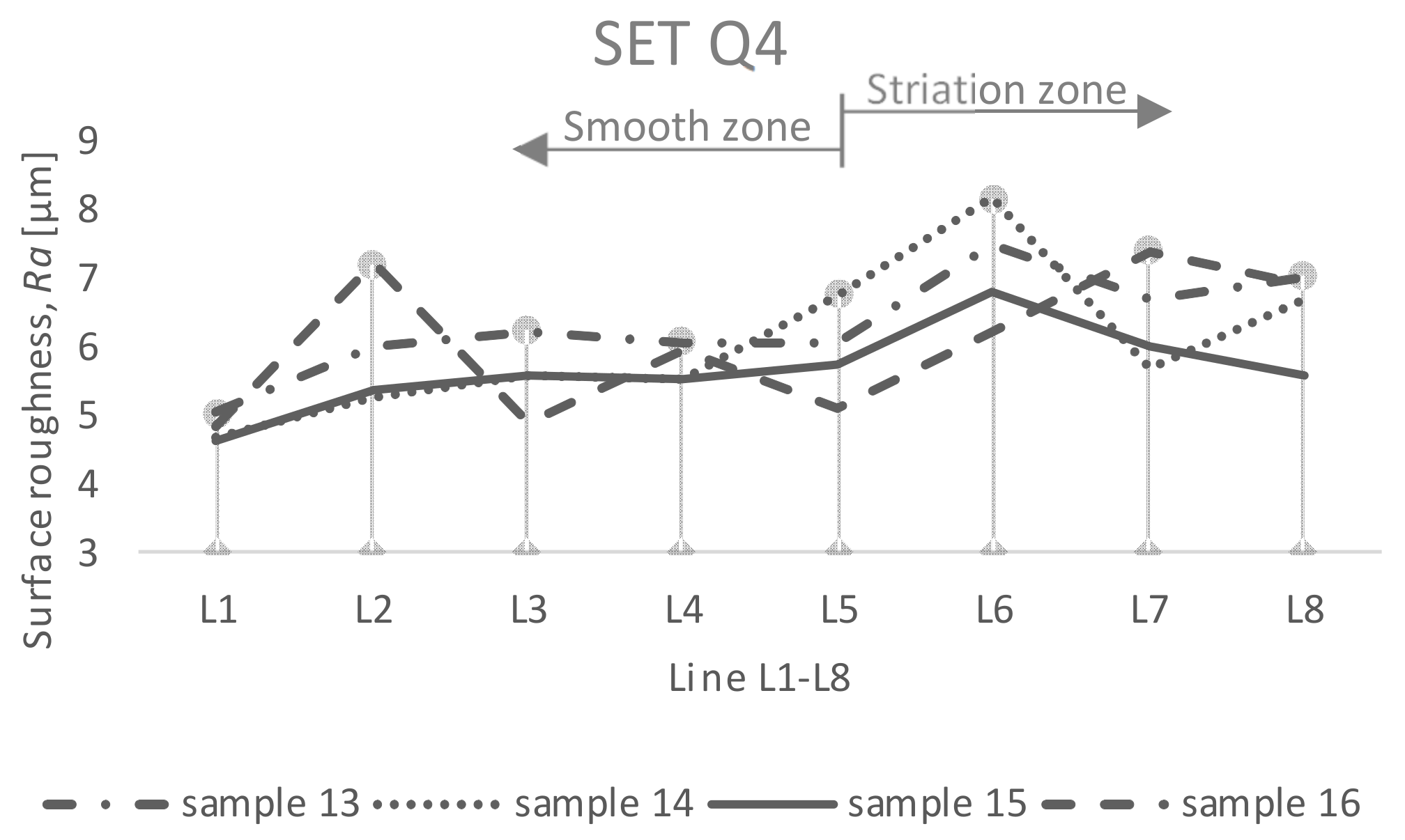
Q4 (set 4)
Machines 10 00566 i004
13 (Ra = 7.04 µm)
14 (Ra = 6.71 µm)
15 (Ra = 5.6 µm)
16 (Ra = 6.9 µm)
(standard value for level Q4)
Ra = 6.3 µm
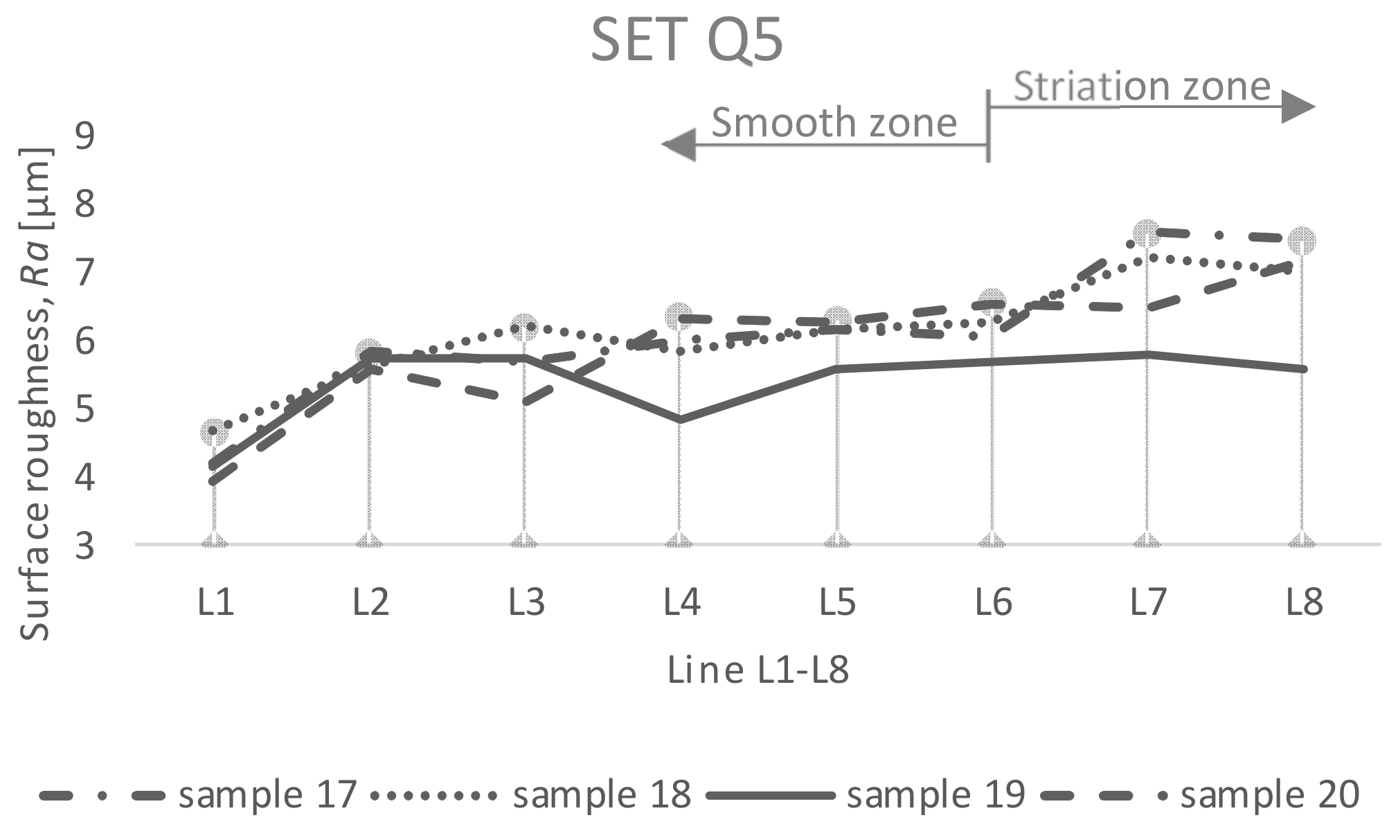
Q5 (set 5)
Machines 10 00566 i005
17 (Ra = 7.48 µm)
18 (Ra = 7.04 µm)
19 (Ra = 5.57 µm)
20 (Ra = 7.18 µm)
(standard value for level Q5)
Ra = 3.2 µm
Ra value specified by standard SN 214001: 2010, samples from 1 to 6, measured value of Ra is not specified, impossible to measure surface roughness parameter Ra in L8 (N/A—measurements not available). Pictures—Inspectis digital zoom microscope.
Publisher’s Note: MDPI stays neutral with regard to jurisdictional claims in published maps and institutional affiliations.

