Article

Obstacle Modeling and Structural Optimization of Four-Track Twin-Rocker Rescue Robot

1
College of Mechanical & Electrical Engineering, Hohai University, Changzhou 213022, China
2
Jiangsu Key Laboratory of Special Robot Technology, Hohai University, Changzhou 213022, China
*
Author to whom correspondence should be addressed.
Machines 2022, 10(5), 365; https://doi.org/10.3390/machines10050365
Submission received: 11 April 2022 / Revised: 7 May 2022 / Accepted: 9 May 2022 / Published: 10 May 2022
(This article belongs to the Special Issue Bio-Inspired Smart Machines: Structure, Mechanisms and Applications)

Abstract

:
In order to achieve the best obstacle surmounting performance of a mobile robot in the rescue environment, a four-track twin-rocker bionic rescue robot with an inner and outer concentric shaft was designed in this paper. From the viewpoint of dynamics, the motion process of the mass center of the robot when climbing steps forward and backward was studied. The maximum obstacle height of the robot was calculated. The relationship between the elevation angle of the car body, the swing angle of the rocker arm and the height of the steps was analyzed by simulation. The simulation results show that the maximum forward and reverse obstacle crossing heights were 92.99 mm and 155.82 mm, respectively. Obstacle climbing experiments of the designed robot prototype were carried out. It was found that the measured maximum height of the step was 95 mm, and the measured maximum height of the reverse obstacle was 165 mm. Finally, bionic particle swarm optimization was used to optimize the structural parameters of the rocker arm with an optimal length of 315.2 mm. The study of this paper can be referenced for the design and analysis of obstacle surmounting rescue robots with similar structures.

1. Introduction

Large-scale natural disasters can cause the collapse of buildings and significant casualties. Rescue workers in harsh environments and the limited time to carry out large-scale search and rescue are the current concerns of people. Using a rescue robot to assist in rescue is an effective means to improve the search area and shorten the rescue time.
At present, rescue robots include wheeled rescue robots, bionic foot rescue robots, hybrid aerial/terrestrial robots and caterpillar rescue robots. Wheeled rescue robots move fast, and the structure and control are simple, but the ability to surmount obstacles is poor, which limits their application to relatively flat terrains. Bionic foot rescue robots can be used in very complicated terrains, but their mechanical structure is complex and their control is tedious. Hybrid aerial/terrestrial robots [1,2] can fly over obstacles and drive on the ground to improve energy efficiency. The ability to autonomously explore complex environments is improved, but the structure and control are more complex. Crawler rescue robots are suitable for surmounting obstacles, with a simpler mechanical structure and control compared with bionic foot robots. Crawler mobile robots can move at a relatively high speed with stability on rugged ground such as steps and slopes. Takemori [3] proposed a multi-functional tracked rescue robot, FUHGA2. The main track covers the main body and carries four sub-tracks, with longer six-axis arms and parallel grippers at the top, giving it high dexterity, maneuverability and high search capability. Cho [4] proposed a rescue robot with a chain double-track mechanism with triangular and square track hinges. The relative rotation of the front and rear body enables the robot to better adapt to the terrain and reduce energy consumption on rugged ground. However, the roof is relatively low from the ground, and it is easy to get stuck in complex terrain, resulting in a low driving speed and efficiency. Kim [5] proposed a single-track crawler rescue robot adapted to obstacles. With different shapes of obstacles, the robot’s mobile planetary wheel structure could change the orbit shape to enhance its ability to overcome different obstacles, but the energy consumption was too large. Li [6] proposed a W-shaped rocker crawler robot through the combination of a four-wheel rocker structure and a crawler. It can avoid the situation where the legs of the W-shaped rocker four-wheel robot are stuck on obstacles, and it can improve the adaptability to chaotic terrain and the stability of obstacle crossing.
In this paper, considering the stability in complex terrains and the ability to jump over obstacles, the crawler movement mode was adopted to accomplish obstacle crossing for a rescue robot. Based on the two-tracked mobile robot, the double rocker arm mechanism was added. To date, four-crawler double rocker rescue robots have received a lot of research attention. Liu [7] proposed a robot with a variable configuration of the rocker arm. A triangular wheel structure in the rocker mechanism and application of the elliptical form principle were used to improve the crawler tension, reduce track deformation and improve the ability to overcome obstacles. The authors of [8,9,10,11,12] proposed four-track twin-rocker rescue robots with good adaptabilities which can climb over rugged terrains, such as convex platforms and gullies. The tracks on the rocker arm are tightly attached to the rigid body, which enables the robot to climb over convex platforms that have good support. However, the rocker arm structure in the above literature is shorter than that of the car body, so the robot can only overcome obstacles in the forward direction, resulting in a small range of forwarding movement of the robot’s center of mass. In the face of higher steps, the robot cannot reverse the obstacle by rotating the rocker arm to support the lifting of the car body. Therefore, through the research and design of the rocker arm structure, the rocker arm of the rescue robot is enough to support the lifting of the car body to reverse the obstacle. In the literature [13], the rocker arm structure was designed based on forward obstacle crossing, so that it can also lift the car body for reverse obstacle crossing by rotating clockwise. However, due to the short length of the rocker arm, the lifting angle of the car body is small, and the height of the reverse obstacle crossing is limited.
Thus, the length of the rocker arm has a great influence on the obstacle surmounting ability, but few studies have looked for the optimal arm length to achieve the maximum obstacle surmounting ability. Given the above obstacle crossing modeling problems of robots, static models [14,15,16,17] with different motion states are usually adopted to realize static analysis, and the obstacle crossing performance of robots is analyzed through the variation rule of the centroid position [18,19] during the robot’s movement.
The innovations of this paper are as follows:
(1)
Through the research and design of the bionic leg-type rocker arm structure, the robot can surmount obstacles upward and downward;
(2)
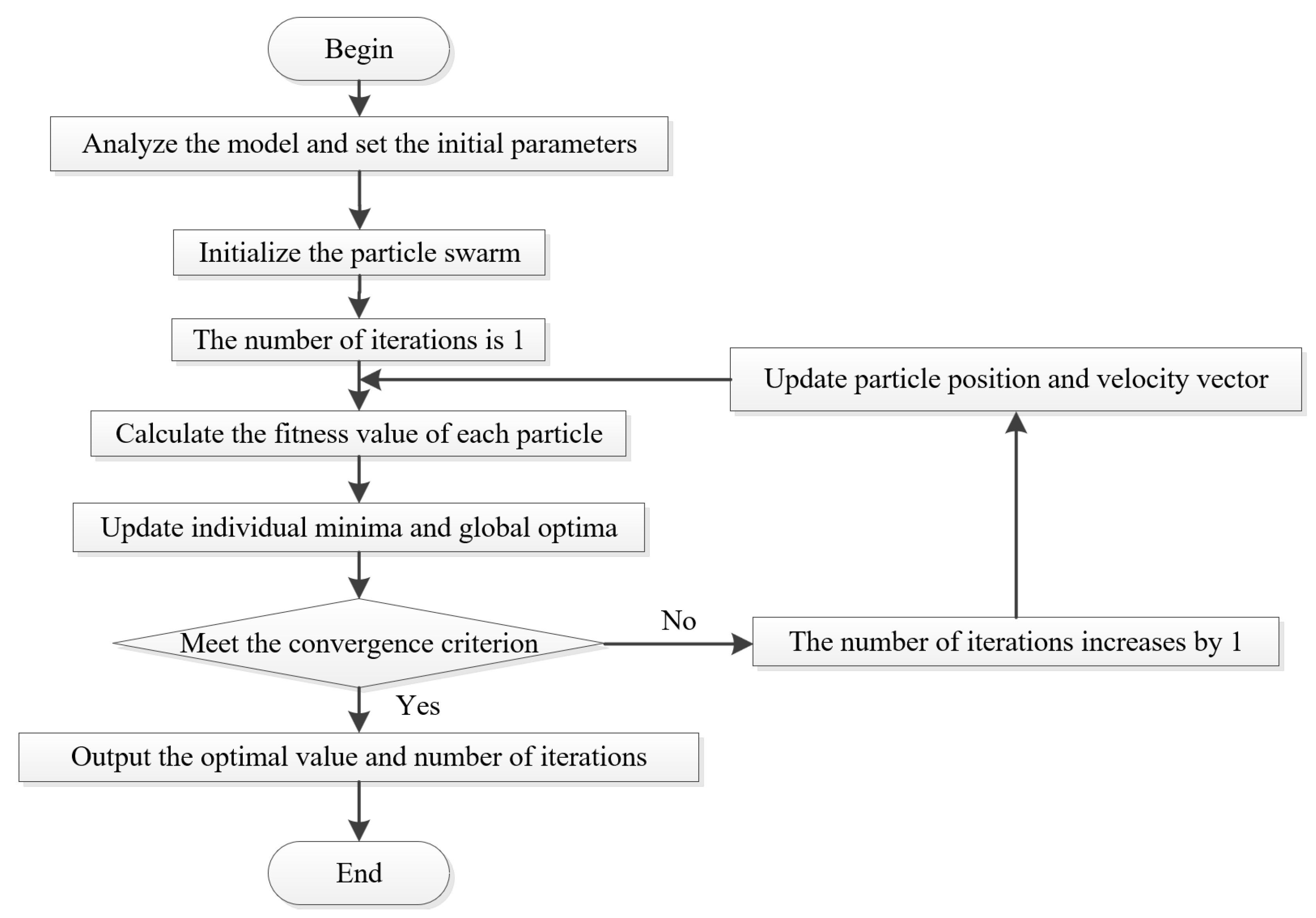
The bionic particle swarm optimization algorithm is used to optimize the structural parameters of the robot, and the optimal length of the rocker arm is obtained to achieve the maximum obstacle crossing capability of the robot.
The rest of this article is organized as follows: In Section 2, the structural design of a four-track twin-rocker rescue robot is described. In Section 3, the mathematical model is established from the perspective of dynamics, and the maximum height that the robot can surmount and the pose when it achieves the best performance of obstacle crossing are deduced according to the position of the robot’s centroid. In Section 4, the simulation and experimental verification of the rescue robot in this study are carried out, and the bionic particle swarm optimization algorithm is used to optimize the structural parameters of the rocker arm. Finally, Section 5 summarizes the research results of this paper.

2. Structure Design of Four-Track Twin-Rocker Arm Robot

A four-track twin-rocker mobile rescue robot was designed, as shown in Figure 1. The robot consists of a chassis, leg rocker system, track system, drive system and external sensor system. The structural design of the double rocker arms of the obstacle surmounting robot mimics the climbing movement of legs. The internal and external concentric shaft design is adopted to satisfy the independent driving of the off-road wheel and rocker arm, and four sets of driving equipment are placed on the same axis to reduce the volume of the car body. The center of gravity of the vehicle is set at the front wheel of the vehicle, which is conducive to crossing rugged terrain and obstacles such as gullies and steps.
The system control diagram is shown in Figure 2. In the figure, STM32F427 is used as the control board, and the whole system is powered by a 24 V mobile power supply. During the operation, it receives the speed instruction issued by the remote control through the serial port and sends the data to the “C610” electrical adjustment. Then, the corresponding PWM signal is calculated and sent to the “M3508” deceleration DC motor and “57AIM30” servo motor to provide power for the track drive system and rocker arm drive system, respectively. The rocker arm drive system guarantees 360° rotation of the rocker arm.
To reduce the weight of the car, the whole vehicle is made of carbon fiber. The car adopts a harmonic reducer and a spiral bevel gear to increase the torque on the rocker up to 120 N · m . The structural parameters are presented in Table 1.

3. Obstacle Crossing Analysis of a Four-Track Twin-Rocker Rescue Robot

In rescue work, the four-track twin-rocker robot faces various terrains, which can be simplified into a combination of typical obstacles such as slopes, steps and ditches. Among these obstacles, steps are often used to analyze the obstacle negotiating capability of the rescue robot.
The obstacle crossing function of the rescue robot is to use a walking mechanism to drive the robot to move so that its center of mass can cross the boundary line of the obstacle. During this process, it should be ensured that the robot does not flip over and remains relatively stable. The obstacle crossing process can be divided into the following two types:
1.
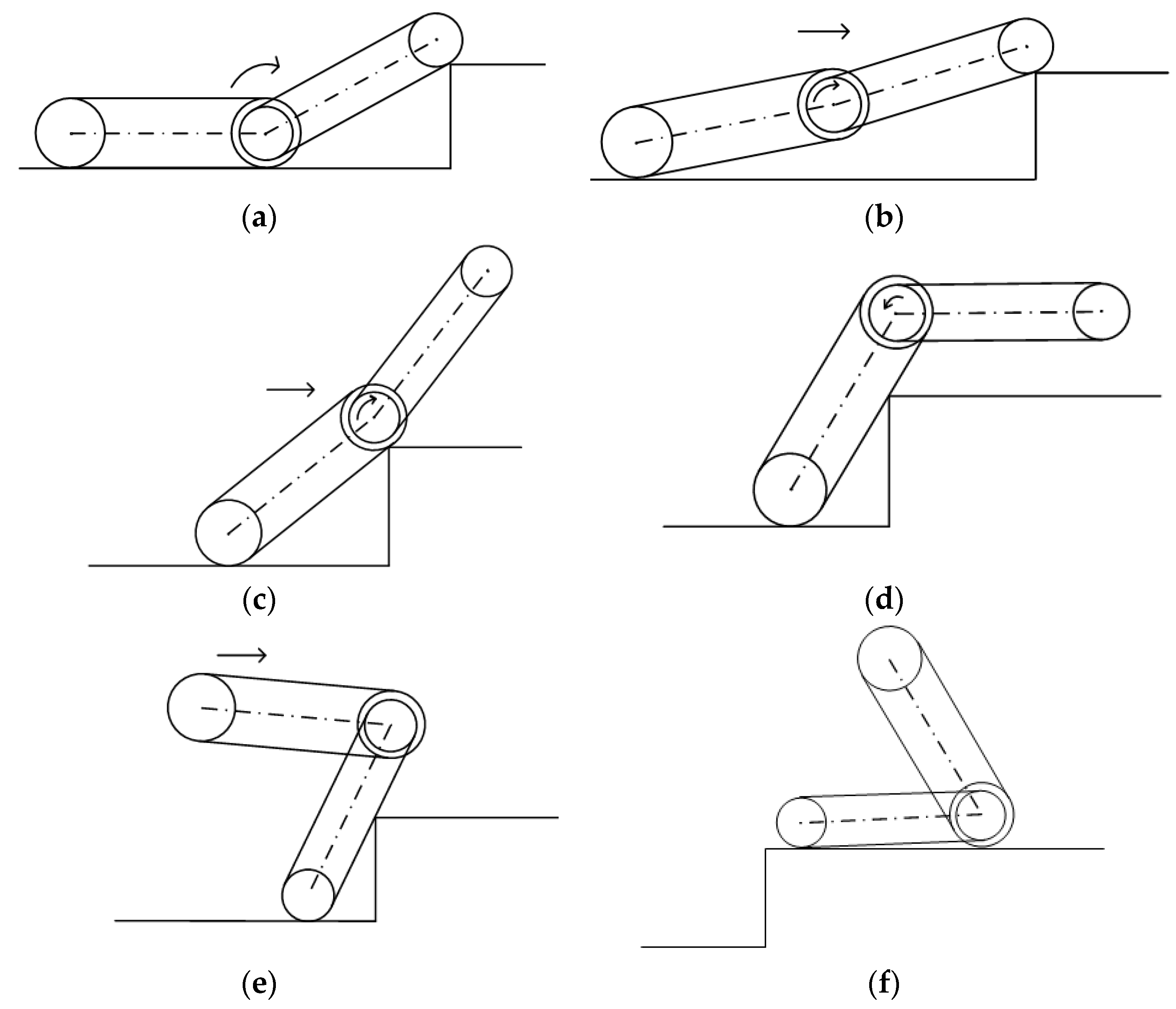
The robot’s forward obstacle surmounting process is shown in Figure 3. The robot is driven by its power to move forward, and the rocker arm rises at a certain distance from the step so that its track wheel can hit and be supported by the rectangular corner of the step, as shown in Figure 3a. Then, the rocker arms rotate clockwise to make the robot body tilt up to a certain angle, as shown in Figure 3b. Under the action of the driving force, the robot moves forward until its mass center crosses the boundary of the step, as shown in Figure 3c. Finally, the robot will be pulled up the step with the force of gravity in the first half of the robot body, as shown in Figure 3d.
2.
The reverse obstacle surmounting process of the robot is shown in Figure 4. The first four steps are identical to the forward obstacle surmounting process in Figure 3a–c. When the driving wheel fails to cross the step boundary only by rotating the double rocker arm clockwise to support the front part of the car body, the rocker arm is rotated backward until it hits and is supported by the ground, causing the center of mass to rise and move forward, as shown in Figure 4e. When the robot is lifted to a certain height, it climbs the step under the joint action of the driving force, friction and support force of the track on the ground, as shown in Figure 4f.

3.1. Centroid Distribution of Four-Track Twin-Rocker Rescue Robot

When climbing stairs, the gesture of the rocker arm needs to be constantly adjusted according to the height of the step. When the angle between the rocker arm and the robot body changes, the position of the robot’s centroid changes accordingly, thus affecting the robot’s obstacle crossing performance.
The robot’s center of mass trajectory is shown in Figure 5. The coordinate system X O 1 Y is established with the center O 1 of the rescue robot’s rear cross-country wheel as the origin, O 1 O 2 as the abscissa and O 1 O 2 as the vertical. G 1 ( L , h ) is the center of mass of the robot body, and G 2 is the center of mass of the robot rocker arm. The variation rule of the robot’s center of mass G ( X , Y ) with the swing arm movement is as follows:
{ X = m 1 m 1 + m 2 L + m 2 ( L 1 + L 2 cos θ ) m 1 + m 2 Y = m 1 m 1 + m 2 h + m 2 L 2 sin θ m 1 + m 2
( X m 1 L + m 2 L 1 m 1 + m 2 ) 2 + ( Y m 1 h m 1 + m 2 ) 2 = m 2 2 L 2 2 ( m 1 + m 2 ) 2
where m 1 is the mass of the robot body, m 2 is the mass of the robot swing arm, L 1 is the center distance between the two driving wheels, L 2 is the distance between the center of the robot swing arm from G 2 to O 2 , L is the abscissa of the robot body’s center of mass, h is the ordinate of the robot body’s center of mass and θ is the swing angle of the robot swing arm.
Therefore, the trajectory of the robot’s center of mass is a circle with ( m 1 L + m 2 L 1 m 1 + m 2 , m 1 h m 1 + m 2 ) as the center and r = m 2 L 2 m 1 + m 2 as the radius.

3.2. Forward Obstacle Crossing Analysis of Four-Track Twin-Rocker Rescue Robot

  • When the step height is low (1–2 cm), the force of the robot crossing the step can be obtained by using the static equilibrium equation, as shown in Figure 6.
Figure 6. Robot’s front wheel’s contact with the step.
Machines 10 00365 g006
The function can be established as
{ F 1 sin α f F 1 cos α G + F 2 = 0 F 1 cos α f F 1 sin α λ F 2 = 0 f F 1 R G L 1 / 2 + F 2 ( L 1 x ) λ F 2 R = 0
According to Equation (3), the function can be expressed as
f R L 1 = ( λ R x + λ f x λ f L 1 λ L 1 ) cos α + λ ( L 1 x ) f x + λ R f λ L 1 sin α
According to Figure 5, the geometric relationship is
sin α = R H R
Substituting Equation (5) into Equation (4) and letting f be 0, Equation (4) can be rewritten as
H R = 1 1 1 + ( L 1 x 1 1 λ R x ) 2
where L 1 is the center distance between the front and rear driving wheels of the robot, R is the radius of the driving wheel, G is the gravity of the robot, F 1 is the support force of the step applied on the front wheel, F 2 is the support force of the ground applied on the rear wheel, f is the rolling resistance coefficient, λ is the ground adhesion coefficient, H is the height of the step and x is the distance between the centroid of the robot and the center of the front wheel.
As can be seen from Equation (6), as the parameters L 1 x and λ R x increase, H R increases. Moreover, it is easier for the front wheel to cross the steps.
2.
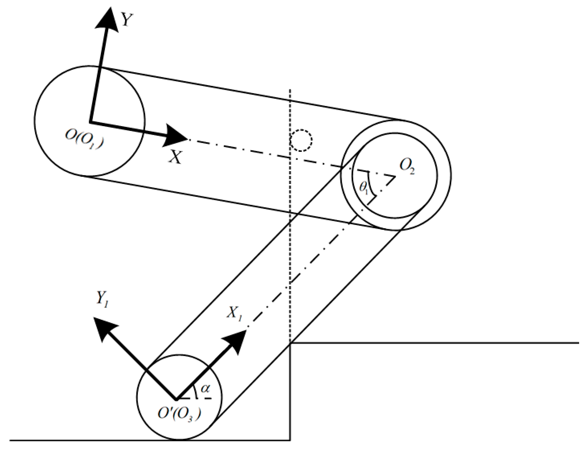
When the rescue robot crosses the step at a certain height while climbing, the vertical edge line of the step is defined as the key boundary line, as shown in Figure 7. When the centroid of the robot hits the vertical edge line of the step, the rocker arm is kept horizontal. The maximum height of the robot crossing steps forward can be calculated:
H ( X , Y , α ) = R + X sin α + Y cos α Y + R cos α
where X is the abscissa of the robot’s center of mass, Y is the ordinate of the robot’s center of mass and α is the angle between the car body and the ground.
To ensure that the rescue robot does not flip over, the elevation angle of the robot needs to satisfy α ( 0 , 90 ) . The relationship between the elevation angle of the robot α and the included angle between the rocker arm and the centerline of the car body θ is
α + θ = 2 π
Take the partial derivative of H ( X , Y , α ) with respect to the abscissa X and ordinate Y of the robot’s centroid and obtain the following formula:
H X = cos α > 0
H Y = sin α sin α cos 2 α < 0
H ( X , Y , α ) is an increasing function and reduction function of the abscissa and ordinate for the robot centroid. When the center of mass of the robot is closer to the front wheel and step, the maximum height to be crossed is higher, and it is easier for the robot to cross the step.
Take the first partial derivative and the second partial derivative of H ( X , Y , α ) with respect to elevation α :
H α = X cos α Y sin α ( Y + R ) sin α cos 2 α
2 H α 2 = X sin α Y cos α 1 + sin 2 α cos 3 α ( Y + R ) < 0
When α ( 0 , π 2 ) , 2 H α 2 < 0 , H has a maximum value. When H α = 0 , the maximum height that the robot can cross can be obtained as H max .

3.3. Reverse Obstacle Crossing Analysis of Four-Track Twin-Rocker Rescue Robot

When the step height is too high, to prevent the robot from flipping over, the forward obstacle crossing cannot be performed by increasing the elevation angle between the robot body and the ground. With O 3 as the support point and O 2 as the rotation center, the rocker arm is rotated counterclockwise to drive the robot’s centroid forward movement. The robot’s centroid can cross the key boundary of the step under the action of the driving force, as shown in Figure 8. The center coordinate system X 1 O Y 1 is established with O 3 as the origin, O 2 O 3 as the horizontal axis and O 2 O 3 as the vertical axis. The centroid coordinate of the robot G ( X , Y ) in the new coordinate system can be expressed as
{ X = m 1 ( L 1 ( L 1 L ) cos θ 1 + h sin θ 1 ) + m 2 ( L 1 L 2 ) m 1 + m 2 Y = m 1 ( h cos θ 1 + ( L 1 L ) sin θ 1 ) m 1 + m 2
where θ 1 is the angle between the centerline O 1 O 2 of the car body and the centerline O 2 O 3 of the rocker arm.
It can be seen that in the new coordinate system X 1 O Y 1 , the trajectory of the robot’s overall centroid changes with θ 1 , which is a circle with ( m 1 L 1 + m 2 ( L 1 L 2 ) m 1 + m 2 , 0 ) as the center and r = m 1 ( L 1 - L ) 2 + h 2 m 1 + m 2 as the radius.
The center of mass of the abscissa of the angle θ 1 derivation can obtain d X d θ 1 = m 1 ( h cos θ 1 + ( L 1 L ) sin θ 1 ) m 1 + m 2 > 0 , and the centroid abscissa increases with the increase in the angle θ 1 , making the center of mass move forward, which favors the surmounting. However, if the included angle θ 1 is too large, the robot will tip forward under the action of inertia forces after crossing the steps, thus causing the car body to overturn. Therefore, as long as X L 1 , the robot will not flip forward around point O 2 . When X = L 1 , m 1 ( L 1 ( L 1 L ) cos θ 1 + h sin θ 1 ) + m 2 L 1 2 m 1 + m 2 = L 1 , the maximum critical value θ 1max = 71.2 can be obtained through calculation.
Figure 9 shows the diagram of the robot’s reverse obstacle crossing when the centroid of the robot happens to be at the key boundary of the step. According to Formula (7), the height of the step under the new coordinate system X 1 O Y 1 has the following relationship with the elevation angle α and included angle θ 1 :
H = r + X sin α + Y cos α Y + r cos α = r + m 1 ( L 1 ( L 1 L ) cos θ 1 + h sin θ 1 ) + m 2 L 1 2 m 1 + m 2 sin α m 1 ( h cos θ 1 + ( L 1 L ) sin θ 1 ) sin 2 α ( m 1 + m 2 ) cos α r sec α
where r is the cross-country wheel radius.
Let the partial derivative of H with respect to angle θ 1 be 0, i.e., H θ 1 = 0 ; then, Equation (15) can be obtained:
m 1 sin α m 1 + m 2 [ ( ( L 1 L ) tan α + h ) cos θ 1 + ( L 1 L h tan α ) sin θ 1 ] = 0
When α ( 0 , 90 ) , θ 1 ( 0 , 71.2 ) and the elevation α and included angles θ 1 satisfy Equation (15), H has the maximum value.

4. Simulation and Experiment

4.1. Simulation Value of Obstacle Crossing Performance

  • The rescue robot crosses the barrier.
Substitute the parameters of the rescue robot into Equation (7). According to the calculation, when the pendulum angle is θ = 318 and the elevation angle is α = 42 , the maximum height is achieved at 92.99 mm. The 3D relationship diagram of the step height, the robot body elevation angle and the rocker arm swing angle parameters for the forward obstacle crossing is obtained, as shown in Figure 10a. It is shown in the figure that when the robot is climbing over step obstacles, when the rocker arm is adjusted to the horizontal state, the height H that the robot can cross rises first and then descends with the increase in the elevation angle α of the car body. Therefore, increasing the elevation angle α of the car body within a certain range is suitable for the step crossing performance.
2.
The rescue robot surmounts the obstacle in reverse.
When the rescue robot adopts reverse climbing steps, the parameters of the robot are substituted into Equation (13). According to the calculation, when the elevation angle α = 37.8 and the included angle θ 1 = 48.6 , the maximum height of the reverse climbing steps of the robot is 155.82 mm. The 3D relationship diagram of the step height H , robot elevation angle α and rocker arm and car body parameter θ 1 for reverse obstacle crossing was obtained by simulation, as shown in Figure 10b. In the range of α ( 0 , 90 ) and θ 1 ( 0 , 71.2 ) , the height H that the robot can cross rises first and then descends with the increase in the angle θ 1 . Therefore, when the robot does not flip over, increasing the angle θ 1 between the rocker arm and the car body benefits the step crossing performance.

4.2. Obstacle Crossing Performance Test

In order to verify the maximum obstacle surmounting capability of the four-track twin-rocker rescue robot, a step with a height of 93 mm, as shown in Figure 11, was selected for forward obstacle surmounting, while a step with a height of 156 mm, as shown in Figure 12, was selected for reverse obstacle surmounting. It can be stated that the rescue machine can surmount the step according to the obstacle surmounting mode shown in Figure 3. In the theoretical calculation, it is assumed that the track is rigid, but in the actual measurement, the track is soft, which leads to a drop in the center of mass when the track touches the ground, which is more conducive for the robot to overcome obstacles. However, when the robot crosses the obstacle in the forward direction, the support force, friction force and tension force of the track between the two off-road wheels are less than those of the track on the rocker arm when crossing the obstacle in the reverse direction. The driving force, friction force and edge line support make it easier for the center of mass to overcome obstacles. As a result, the maximum obstacle surmounting ability of the robot in reverse is stronger than that when moving forward. The measured value of the maximum height that can be crossed in the forward direction is 95 mm. The measured maximum height that can be crossed in reverse is 165 mm.

4.3. Optimization Design of Structural Parameters

Through experiments, it was found that the length of the rocker arm has a great influence on the performance of the reverse obstacle surmounting. In order to further improve the performance of obstacle surmounting, particle swarm optimization was adopted to optimize the structural parameters of the robot’s double rocker arm. The bionic particle swarm is initialized by setting the number of particles in the swarm, the maximum number of iterations and the position parameters. The optimal solution of a single particle and the global optimal solution for the population are obtained according to the fitness function. By iterations, if the fitness value of the new-found particle is better than that of the previous one, the particle position and historical optimal solution are updated and compared with the current global optimal solution. If the individual extreme values of all particles are better than the current global optimal solution, the solution is updated, and the position of the particle is recorded until the maximum number of iterations is reached or the optimal result has been found. The specific procedure is shown in Figure 13.
Figure 14 shows that when the number of iterations is 9, the curve gradually converges. When L 2 = 157.59   mm , and the optimal length of the rocker arm is 315.18 mm, the maximum obstacle crossing performance of the robot can be achieved. For L 2 = 157.59   mm and L 2 = 189   mm , the curved surfaces of the crossing height H versus the elevation angle α and the included angle θ 1 are shown in Figure 15. It can be seen that when L 2 = 157.59   mm , the maximum height of the reverse climbing step of the robot is 171.58 mm, which is 10.15% higher than the maximum obstacle height that can be crossed when L 2 = 189   mm .

5. Discussion

Table 2 provides a brief comparison with previously proposed four-track twin-rocker robots. From the table, we can see that the mass of the double rocker arm in the literature [8,11] is relatively short, and only forward obstacle crossing can be carried out, thus reducing the obstacle crossing performance. Moreover, the obstacle crossing ability is only simulated without actual measurement. In addition, almost all the previous studies emphasized the influence of the arm’s length on the robot’s obstacle crossing function. The following conclusions are drawn: The increase in the centroid height and the forward shift in position provide more favorable conditions for climbing steps and increase the turning moment required for obstacle crossing. The change of centroid is closely related to the arm length, but few people optimize the arm length through the particle swarm optimization algorithm. Therefore, it is of great significance to combine simulations and experiments to optimize the arm length structure.

6. Conclusions

Along with the structure of the four-track twin-rocker rescue robot, the mathematical model of the robot climbing steps forward and backward was established in this paper. The theoretical formula of the pose state of the robot was derived to achieve the maximum obstacle surmounting performance. The obstacle crossing performance of the four-track twin-rocker rescue robot was analyzed by simulation. Particle swarm optimization was used to optimize the structure of the rocker arm, and the following conclusions were obtained:
  • By comparing the theoretical calculation with the experiment, it can be seen that the experimental measurement was larger. The measured maximum forward and reverse crossing heights were 93 mm and 156.1 mm, respectively.
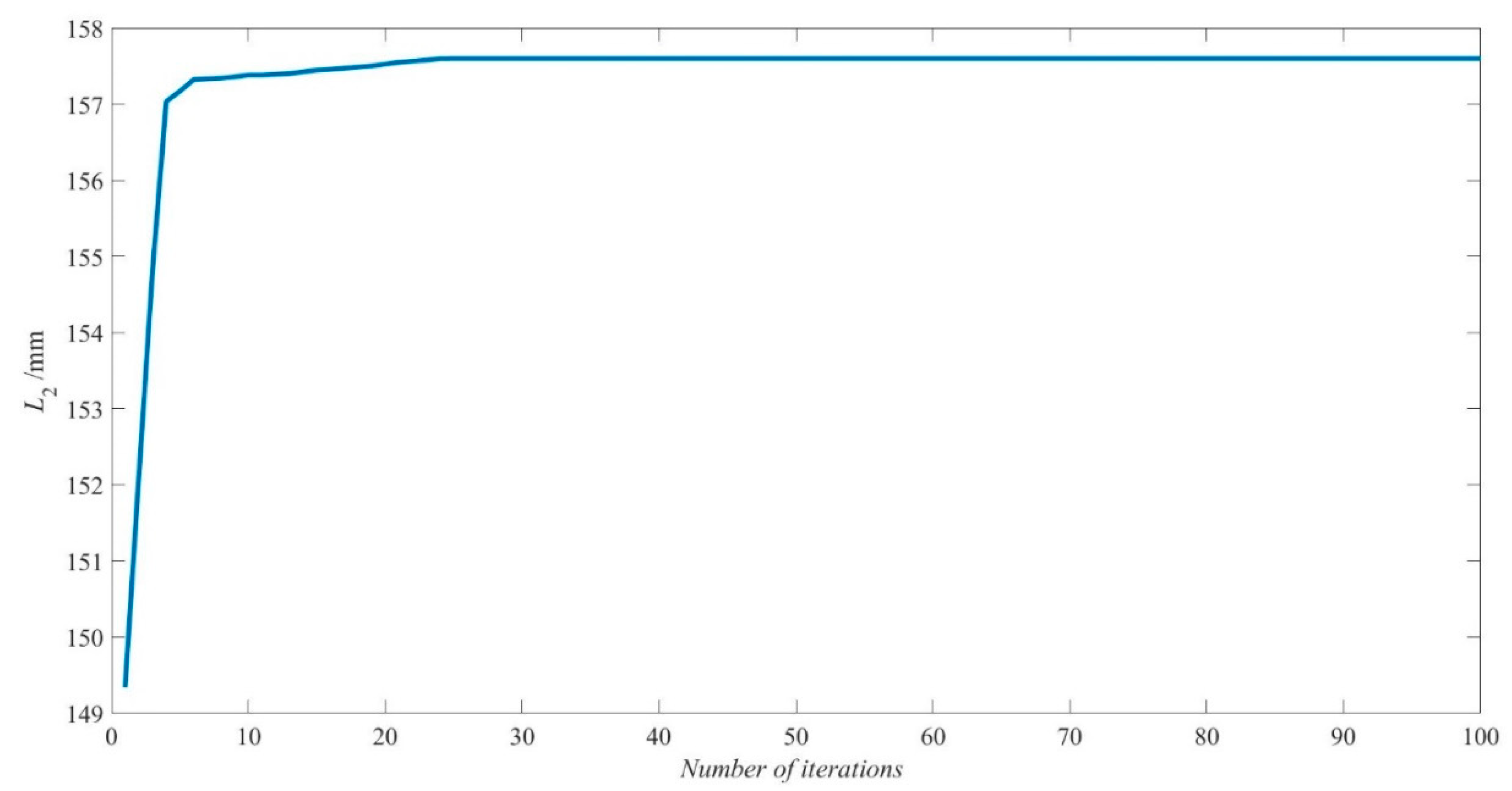
  • Combined with the simulation and experiment, it was found that the length of the rocker arm is critical to the obstacle surmounting process. The particle swarm optimization algorithm was used to optimize the structural parameters of the robot, and the optimal arm length of the robot to achieve the maximum obstacle surmounting ability was found to be 315.18 mm.

Author Contributions

Conceptualization, X.X. and W.W.; methodology, X.X. and W.W.; software, X.X. and G.S.; validation, X.X., W.W. and C.L.; formal analysis, X.X., W.W. and H.Z.; investigation, X.X., H.Z. and C.L.; resources, X.X.; data curation, X.X. and G.S.; writing—original draft preparation, X.X. and W.W.; writing—review and editing, X.X. and W.C.; visualization, X.X.; supervision, Y.R., Z.T. and M.L.; project administration, X.X.; funding acquisition, X.X. All authors have read and agreed to the published version of the manuscript.

Funding

This research was funded by the Changzhou Sci&Tech Program (Grant No. CE20215041), the Fundamental Research Funds for the Central Universities (Grant No. B220202023) and the Jiangsu Key R&D Program (Grant No. BE2020082-1).

Institutional Review Board Statement

Not applicable.

Informed Consent Statement

Not applicable.

Data Availability Statement

Not applicable.

Conflicts of Interest

The authors declare no conflict of interest.

References

  1. Premachandra, C.; Otsuka, M.; Gohara, R.; Ninomiya, T.; Kato, K. A study on development of a hybrid aerial terrestrial robot system for avoiding ground obstacles by flight. IEEE/CAA J. Autom. Sin. 2018, 6, 327–336. [Google Scholar] [CrossRef]
  2. Zhang, D.; Guo, C.; Ren, H.; Zhu, P.; Xu, M.; Lu, H. The Design of an Aerial/Ground Dual-Modal Mobile Robot for Exploring Complex Environments. In Proceedings of the 2021 IEEE International Conference on Real-Time Computing and Robotics (RCAR), Xining, China, 15–19 July 2021; IEEE: Piscataway, NJ, USA; pp. 393–398. [Google Scholar]
  3. Takemori, T.; Miyake, M.; Hirai, T.; Wang, X.; Fukao, Y.; Adachi, M.; Yamaguchi, K.; Tanishige, S.; Nomura, Y.; Matsuno, F.; et al. Development of the multifunctional rescue robot FUHGA2 and evaluation at the world robot summit 2018. Adv. Robot. 2019, 34, 119–131. [Google Scholar] [CrossRef]
  4. Cho, C.; Lee, W.; Kang, S.; Kim, M.; Song, J.-B. Uneven terrain negotiable mobile platform with passively adaptive double tracks and its application to rescue missions. Adv. Robot. 2005, 19, 459–475. [Google Scholar] [CrossRef] [Green Version]
  5. Kim, J.; Lee, C.; Kim, G. Study of machine design for a transformable shape single-tracked vehicle system. Mech. Mach. Theory 2010, 45, 1082–1095. [Google Scholar] [CrossRef]
  6. Li, Y.W.; Ge, S.R.; Zhu, H.; Fang, H.F. Mobile Platform of a Rocker-Type W-Shaped Track Robot. Key Eng. Mater. 2010, 419–420, 609–612. [Google Scholar] [CrossRef]
  7. Liu, S.; Guo, Y.; Jia, H.; Lin, S.; Zhao, D. Mechanism principle and obstacle-crossing analysis of robot with automatic-strained track and variable main arm configuration. J. Cent. South Univ. 2013, 44, 2289–2297. [Google Scholar]
  8. Xue, T.; Liu, R.; Zhai, S.M. Structure Design and Analysis of Moving Character for Detect Robot for Underground Coal Mine. Appl. Mech. Mater. 2014, 526, 205–210. [Google Scholar] [CrossRef]
  9. Han, X.; Lin, M.; Wu, X.; Yang, J. Design of an Articulated-Tracked Mobile Robot with Two Swing Arms. In Proceedings of the 2019 IEEE 4th International Conference on Advanced Robotics and Mechatronics (ICARM), Toyonaka, Japan, 3–5 July 2019; IEEE: Piscataway, NJ, USA; pp. 684–689. [Google Scholar]
  10. Li, C.S.; Cui, G.Q.; Pang, S.H. Dynamic Modeling and Analysis of a Mobile Robot for Multi-Movement States. J. Hebei Univ. Technol. 2009, 38, 31–35. [Google Scholar]
  11. Fang, H.F.; Ge, S.R.; Li, Y.W. Obstacle Performance Analysis of Four-Track Robot with Compliant Swing Arms. J. China Univ. Min. Technol. 2010, 39, 682–686. [Google Scholar]
  12. Xie, S.; Bao, S.; Zou, B.; Pu, H.; Luo, J.; Gu, J. The research on obstacle-surmounting capability of six-track robot with four swing arms. In Proceedings of the 2013 IEEE International Conference on Robotics and Biomimetics (ROBIO), Shenzhen, China, 12–14 December 2013; IEEE: Piscataway, NJ, USA, 2013; pp. 2441–2445. [Google Scholar] [CrossRef]
  13. Li, Y.; Ge, S.; Hua, Z.; Zhu, H.; Liu, J. Obstacle-Surmounting Mechanism and Capability of Four-Track Robot with Two Swing Arms. Robot 2010, 32, 157–165. [Google Scholar] [CrossRef]
  14. Ye, C.; Li, J.; Yu, S.; Ding, G. Movement Analysis of Rotating-Finger Cable Inspection Robot. Int. Conf. Intell. Robot. Appl. 2019, 11744, 326–337. [Google Scholar] [CrossRef]
  15. Cui, D.; Gao, X.; Guo, W.; Li, J. Multimode obstacle-crossing analysis of a wheel/track mobile robot. In Proceedings of the 2017 IEEE International Conference on Unmanned Systems (ICUS), Beijing, China, 17–29 October 2017; IEEE: Piscataway, NJ, USA, 2017; pp. 197–203. [Google Scholar] [CrossRef]
  16. Ma, J.M.; Li, X.F.; Yao, C.; Wang, Z. Dynamic Modeling and Analysis for Obstacle Negotiation of Ground Mobile Robot. Robot 2008, 30, 273–278. [Google Scholar]
  17. Wang, W.; Du, Z.; Sun, L. Dynamic Load Effect on Tracked Robot Obstacle Performance. In Proceedings of the 2007 IEEE International Conference on Mechatronics, Kumamoto, Japan, 8–10 May 2007; IEEE: Piscataway, NJ, USA, 2007; pp. 370–375. [Google Scholar] [CrossRef]
  18. Yamada, Y.; Miyagawa, Y.; Yokoto, R.; Endo, G. Development of a Blade-Type Crawler Mechanism for a Fast Deployment Task to Observe Eruptions on Mt. Mihara. J. Field Robot. 2015, 33, 371–390. [Google Scholar] [CrossRef]
  19. Ye, C.Q.; Shang, W.Y.; Xu, Z.P.; Liu, J.J.; Huang, Q.R.; An, B. Structural Design of Robot Applied in Post-Earthquake Relief. Appl. Mech. Mater. 2013, 437, 619–622. [Google Scholar] [CrossRef]
Figure 1. Four-track twin-rocker arm mobile robot object.
Machines 10 00365 g001
Figure 2. The system control diagram.
Machines 10 00365 g002
Figure 3. The process of the robot climbing the steps forward: (a) lift the rocker arm; (b) lift the body with the support of the rocker arm; (c) the center of mass crosses the step boundary; (d) the body crosses the step.
Machines 10 00365 g003
Figure 4. Reverse climbing process of the robot: (a) lift the rocker arm; (b) lift the body with the support of the rocker arm; (c) off-road wheel withstands step angle; (d) car body crawler withstands step edges; (e) the center of mass crosses the step boundary; (f) the body crosses the step.
Machines 10 00365 g004
Figure 5. The trajectory of the robot’s center of mass.
Machines 10 00365 g005
Figure 7. Robot centroid crossing the step boundary in forward obstacle crossing.
Machines 10 00365 g007
Figure 8. Lifting the state of the car body supported by the rocker arm.
Machines 10 00365 g008
Figure 9. Robot centroid crossing the step boundary in reverse obstacle crossing.
Machines 10 00365 g009
Figure 10. Simulation analysis: (a) with a positive obstacle height H , body elevation angle α and radial angle θ of the 3D curved surface; (b) reverse with the obstacle height H , body elevation angle α and rocker arm and body angle θ 1 of the 3D surface.
Machines 10 00365 g010
Figure 11. Robot climbing up steps: (a) lift the rocker arm; (b) track wheels against the step; (c) centroid crossing the step; (d) car body over the step.
Machines 10 00365 g011
Figure 12. Reverse climbing process of the robot: (a) lift the rocker arm; (b) track wheels against the step; (c) body track against the step; (d) radial supporting body; (e) centroid crossing the step; (f) car body crosses the step.
Machines 10 00365 g012
Figure 13. Flow chart of the particle swarm optimization algorithm.
Machines 10 00365 g013
Figure 14. Convergence curve of L 2 with the number of iterations.
Machines 10 00365 g014
Figure 15. Comparison of obstacle heights with different arm lengths.
Machines 10 00365 g015
Table 1. Structural parameters of a four-track twin-rocker mobile robot.
IndicatorsParameter
Size/mm × mm × mm378 × 300 × 136.5
Diameter of track wheel/mm173
Cross-country wheel diameter/mm143.5
Rocker arm mass/kg0.189
Car body quality/kg12.94
Table 2. Comparison of our four-track twin-rocker robot with similar structures.
Xue [8]Fang [11]Li [13]Wang [17]This Paper
Body length/mm100350350400378
Rocker arm length/mm45150225350378
Obstacle was reversedNoNoYesYesYes
Actual measurement was conductedNoNoYesYesYes
Structure was optimizedNoNoNoNoYes
Publisher’s Note: MDPI stays neutral with regard to jurisdictional claims in published maps and institutional affiliations.

