
Design and Modeling of a Bio-Inspired Compound Continuum Robot for Minimally Invasive Surgery

 ,
, 
Abstract
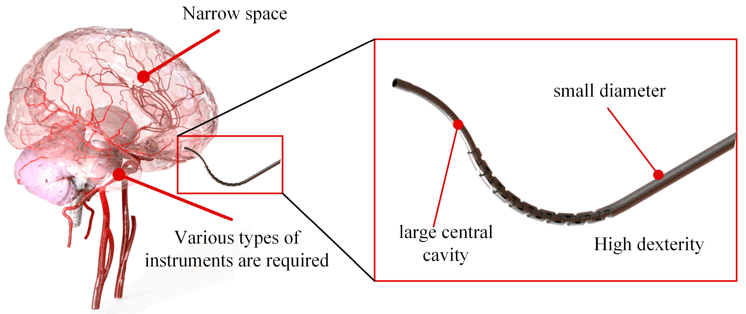
:1. Introduction
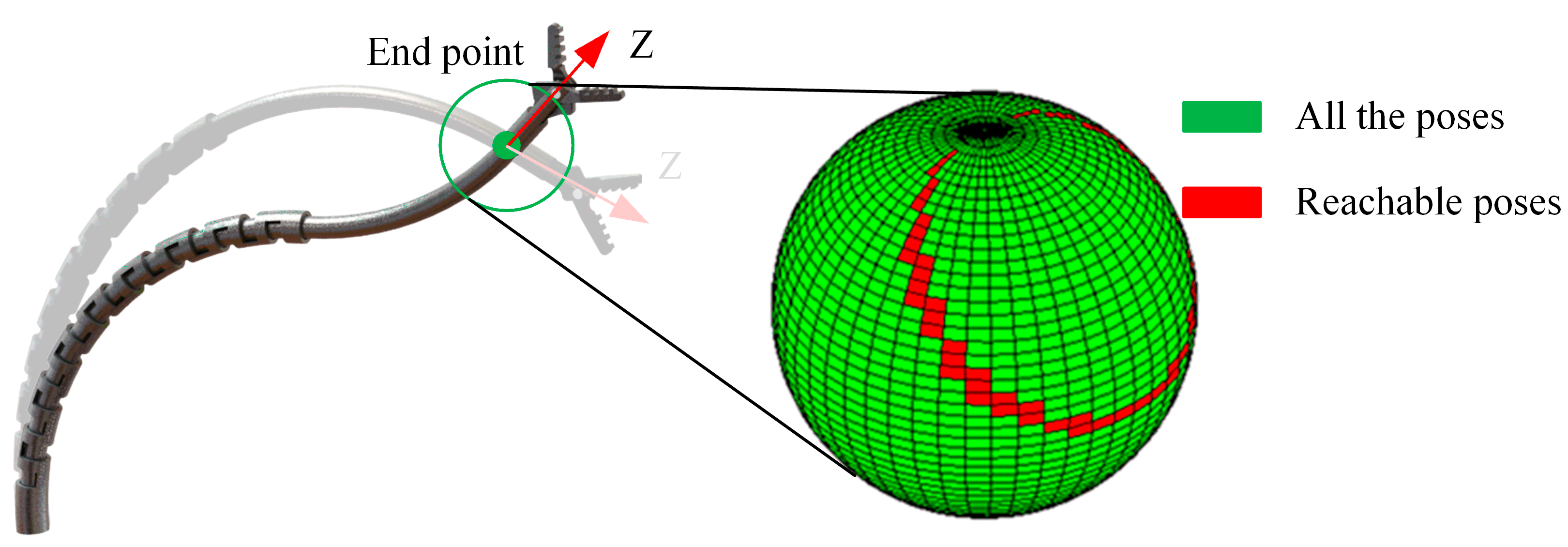
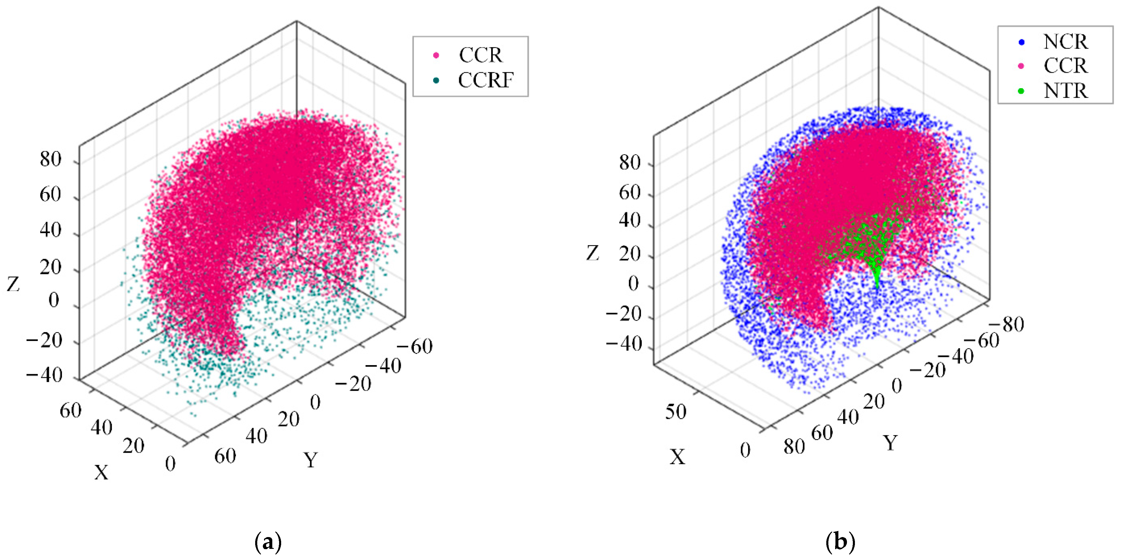
- A compound continuum robot (CCR) combining the concentric tube continuum robot (CTR) and the notched continuum robot is proposed to design high-dexterity minimally invasive surgical instruments. The simulations show that the CCR’s workspace is bigger than that of the CTR and that the dexterity indices of the CCR are 1.231 times larger than those of the CTR.
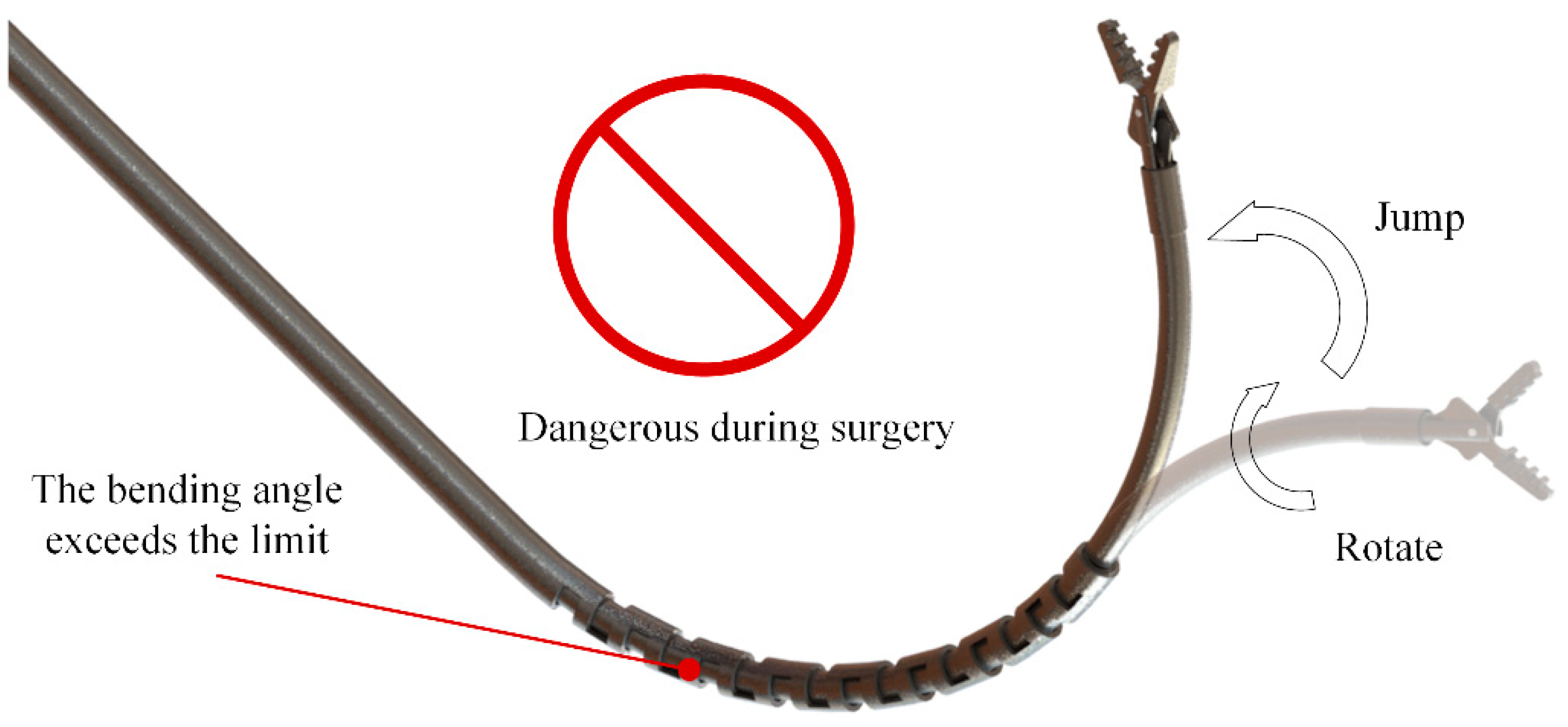
- Stability issues in the CTR part were considered. The failure boundaries of the workspace are defined. In the newly defined workspace, the CCR can perform stable movements. The CTR section avoids instability.
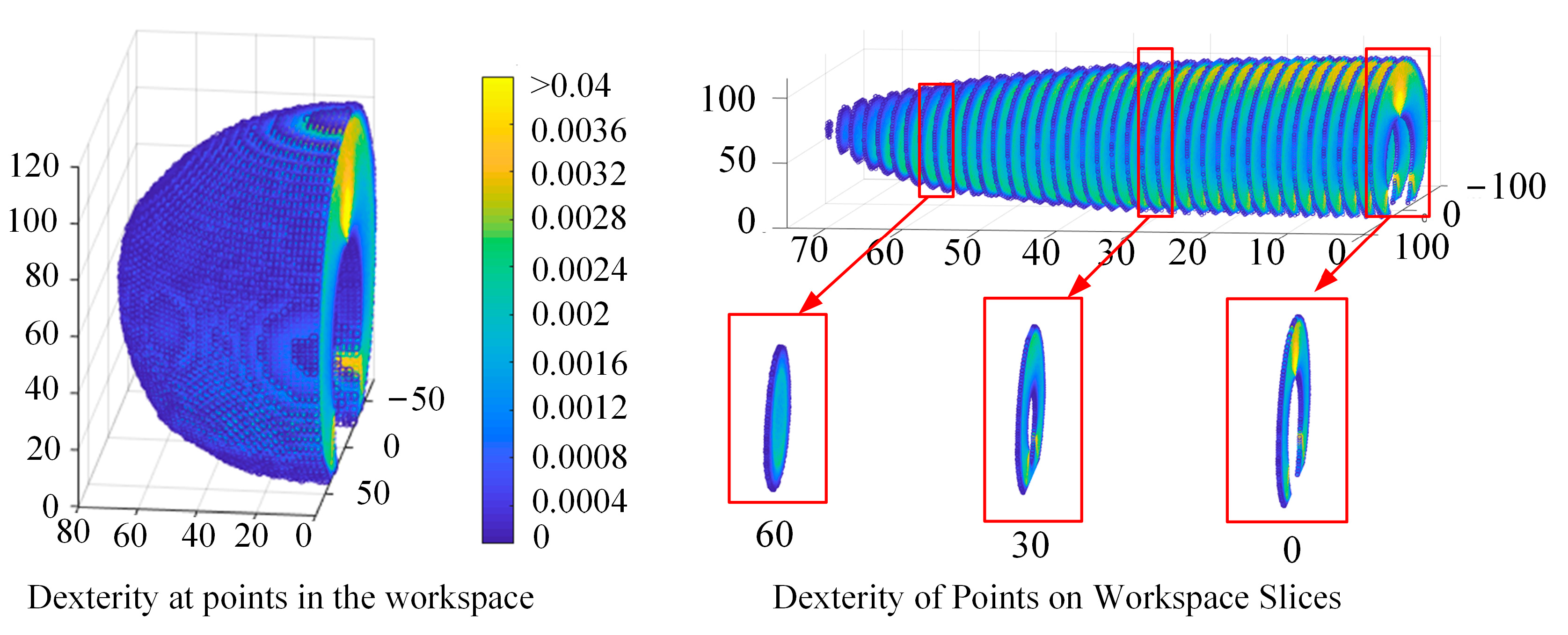
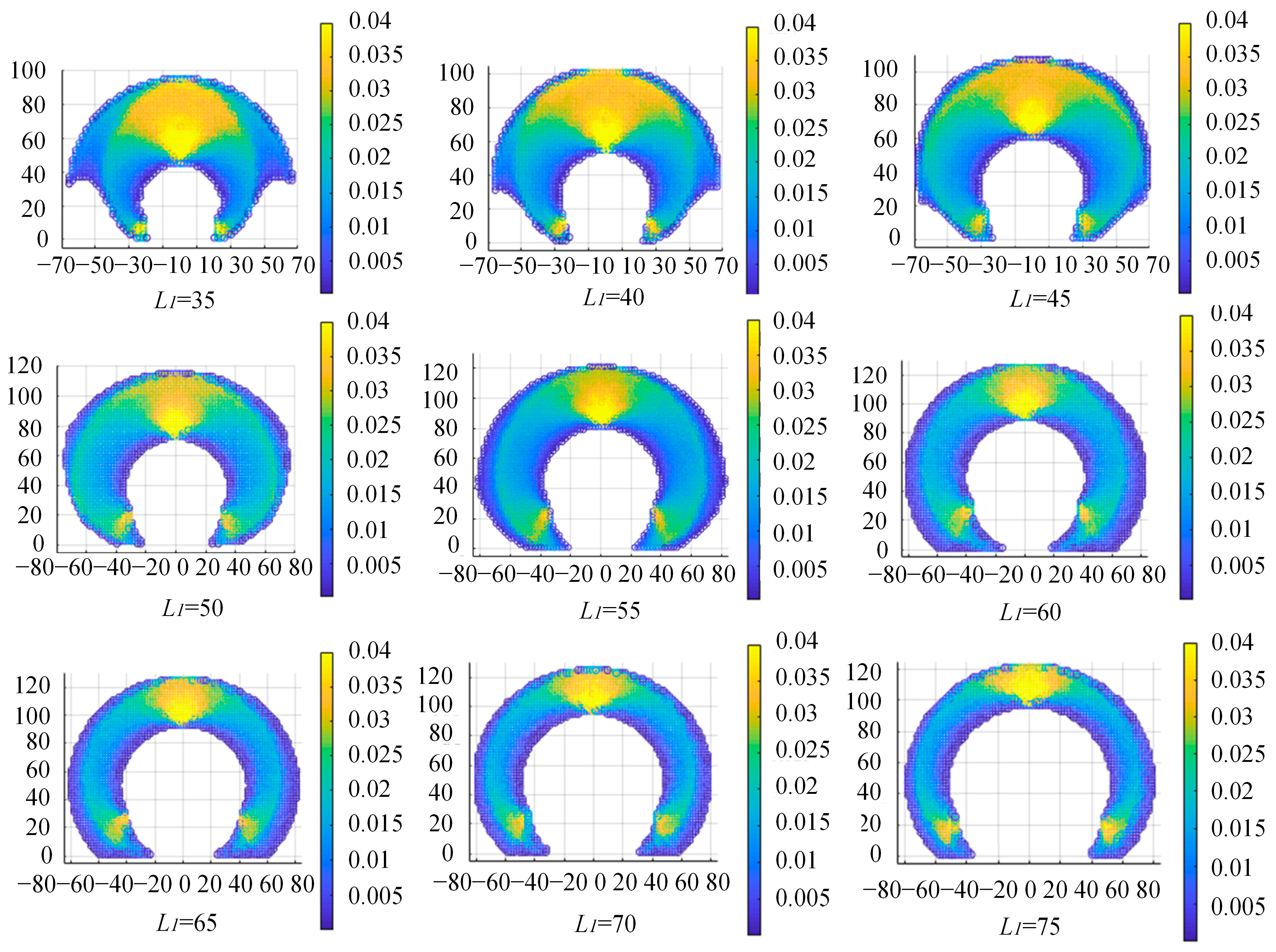
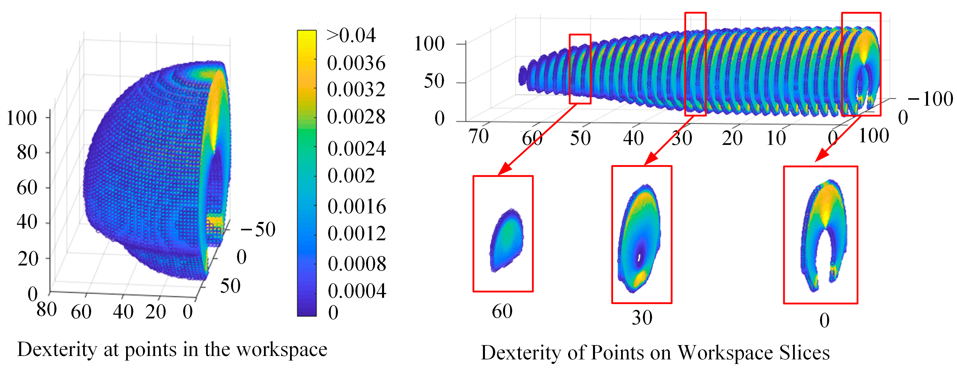
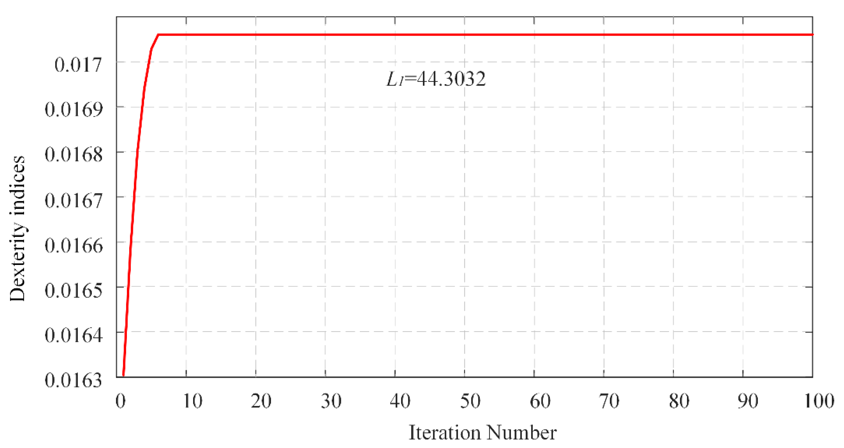
- The dexterity index of the CCR is proposed. The length distribution of the compound continuum robot is optimized using a fruit fly algorithm based on the dexterity index.
2. Problem Formulation
3. Methods
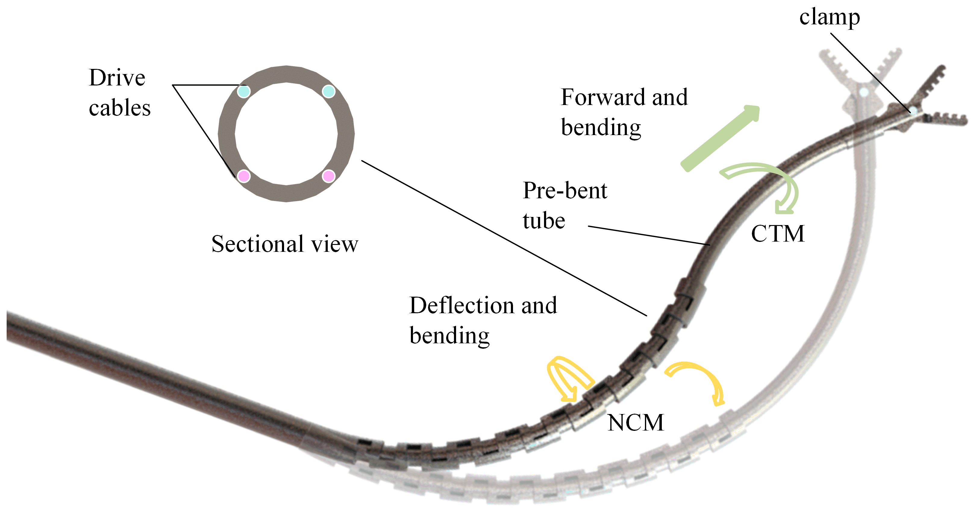
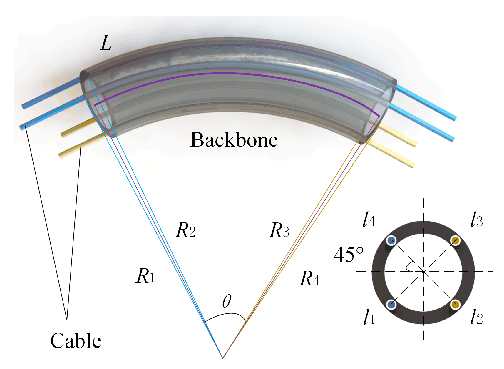
3.1. Design and Mechanism of Compound Continuum Robot
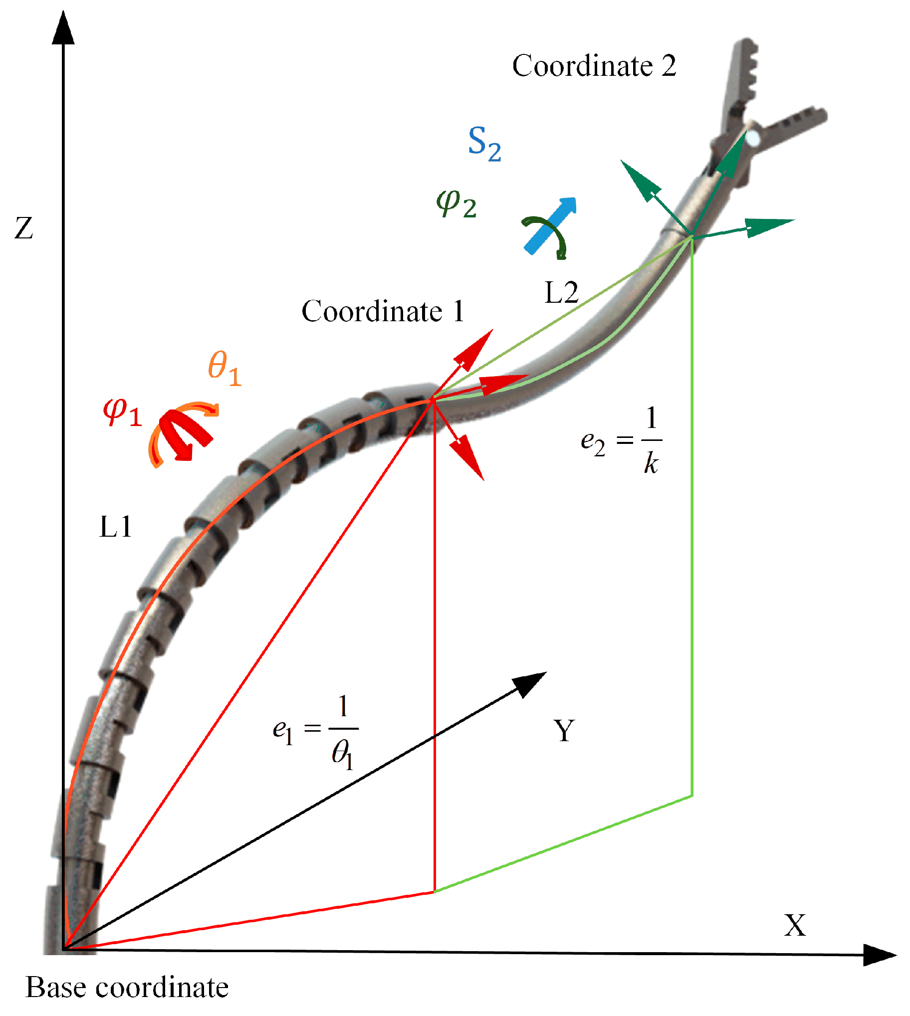
3.2. Kinematics Model and Smooth-Running Workspace
3.3. Dexterity Evaluation and Optimization
4. Results and Discussion
4.1. Workspace
4.2. Dexterity Comparison between the CTR and CCR
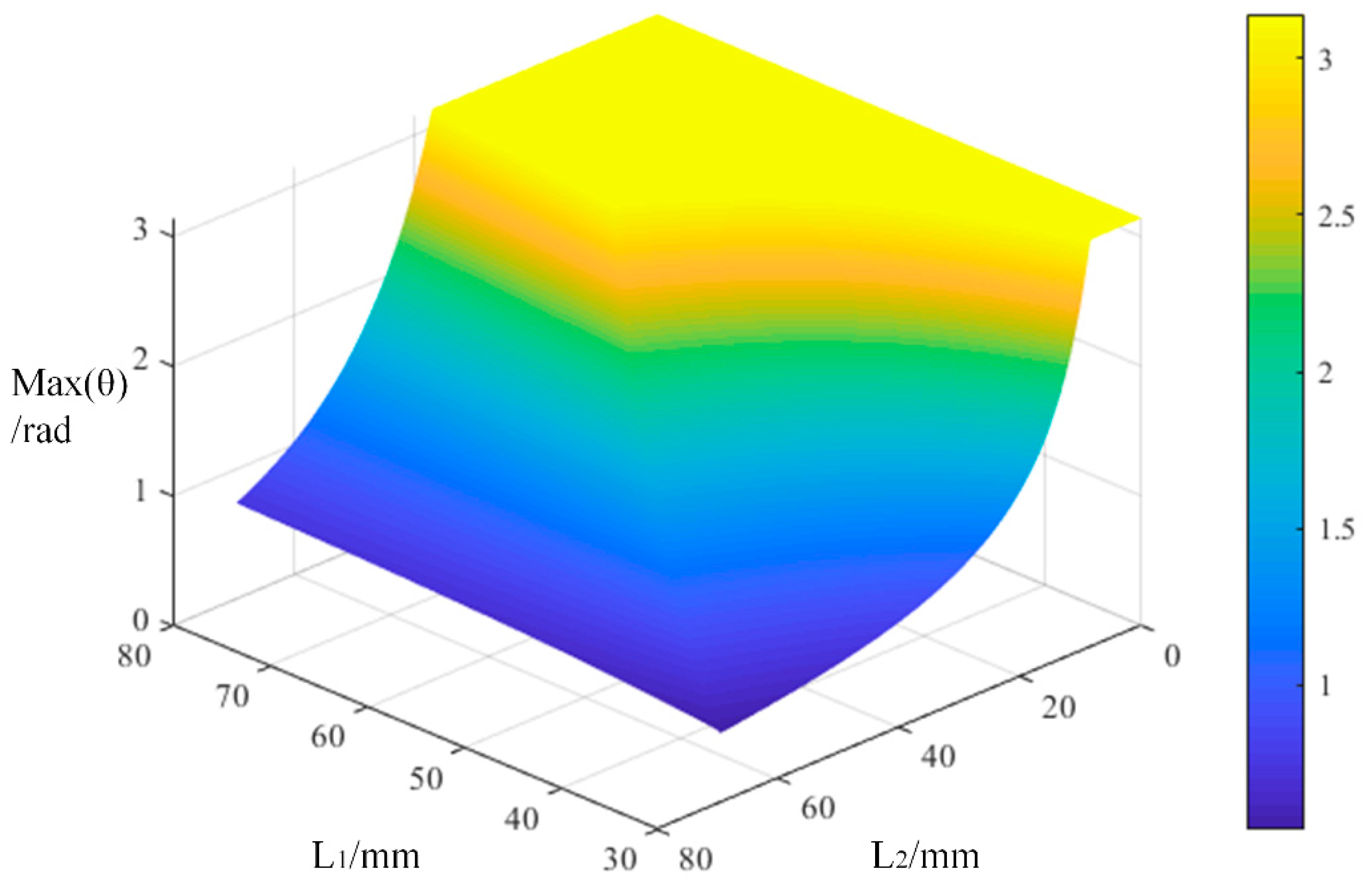
4.3. Length Distribution Optimization
5. Conclusions
Author Contributions
Funding
Data Availability Statement
Conflicts of Interest
References
- Da Veiga, T.; Chandler, J.; Lloyd, P.; Pittiglio, G.; Wilkinson, N.J.; Hoshiar, A.K.; Harris, R.A.; Valdastri, P. Challenges of continuum robots in clinical context: A review. Prog. Biomed. Eng. 2020, 2, 032003. [Google Scholar] [CrossRef]
- Kolachalama, S.; Lakshmanan, S. Continuum Robots for Manipulation Applications: A Survey. J. Robot. 2020, 2020, 4187048. [Google Scholar] [CrossRef]
- Li, S.; Hao, G. Current Trends and Prospects in Compliant Continuum Robots: A Survey. Actuators 2021, 10, 145. [Google Scholar] [CrossRef]
- Lu, J.; Du, F.; Yang, F.; Zhang, T.; Lei, Y.; Wang, J. Kinematic modeling of a class of n-tendon continuum robots. Adv. Robot. 2020, 34, 1254–1271. [Google Scholar] [CrossRef]
- Püschel, A.; Schafmayer, C.; Groß, J. Robot-assisted techniques in vascular and endovascular surgery. Langenbeck’s Arch. Surg. 2022, 1–7. [Google Scholar] [CrossRef] [PubMed]
- Iwasa, T.; Nakadate, R.; Onogi, S.; Okamoto, Y.; Arata, J.; Oguri, S.; Ogino, H.; Ihara, E.; Ohuchida, K.; Akahoshi, T.; et al. A new robotic-assisted flexible endoscope with single-hand control: Endoscopic submucosal dissection in the ex vivo porcine stomach. Surg. Endosc. 2018, 32, 3386–3392. [Google Scholar] [CrossRef]
- Lei, Y.; Li, Y.; Song, R.; Du, F. Development of a novel deployable arm for natural orifice transluminal endoscopic surgery. Int. J. Med Robot. Comput. Assist. Surg. 2021, 17, e2232. [Google Scholar] [CrossRef]
- Almendárez, M.; Alvarez-Velasco, R.; Pascual, I.; Alperi, A.; Moris, C.; Avanzas, P. Transseptal puncture: Review of anatomy, techniques, complications and challenges, a critical view. Int. J. Cardiol. 2022, 351, 32–38. [Google Scholar] [CrossRef]
- Seung, S.; Liu, P.; Park, S.; Park, J.-O.; Ko, S.Y. Single-port robotic manipulator system for brain tumor removal surgery: SiromanS. Mechatronics 2015, 26, 16–28. [Google Scholar] [CrossRef]
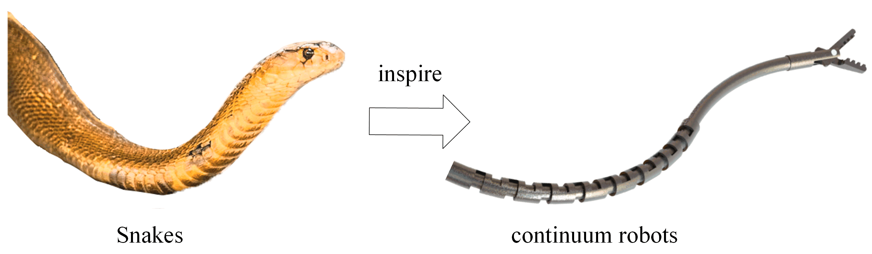
- Seetohul, J.; Shafiee, M. Snake Robots for Surgical Applications: A Review. Robotics 2022, 11, 57. [Google Scholar] [CrossRef]
- Burgner-Kahrs, J.; Rucker, D.C.; Choset, H. Continuum Robots for Medical Applications: A Survey. IEEE Trans. Robot. 2015, 31, 1261–1280. [Google Scholar] [CrossRef]
- Li, Z.; Du, R.; Lei, M.C.; Yuan, S.M. Design and analysis of a biomimetic wire-driven robot arm. In Proceedings of the ASME International Mechanical Engineering Congress and Exposition, Denver, CO, USA; 2011; Volume 54938, pp. 91–198. [Google Scholar]
- Li, Z.; Du, R. Design and Analysis of a Bio-Inspired Wire-Driven Multi-Section Flexible Robot. Int. J. Adv. Robot. Syst. 2013, 10, 209. [Google Scholar] [CrossRef]
- Li, Z.; Du, R.; Yu, H.; Ren, H. Statics modeling of an underactuated wire-driven flexible robotic arm. In Proceedings of the 5th IEEE RAS/EMBS International Conference on Biomedical Robotics and Biomechatronics, Sao Paulo, Brazil, 12–15 August 2014; pp. 326–331. [Google Scholar]
- Xu, K.; Simaan, N. An Investigation of the Intrinsic Force Sensing Capabilities of Continuum Robots. IEEE Trans. Robot. 2008, 24, 576–587. [Google Scholar] [CrossRef]
- Simaan, N.; Xu, K.; Wei, W.; Kapoor, A.; Kazanzides, P.; Taylor, R.; Flint, P. Design and Integration of a Telerobotic System for Minimally Invasive Surgery of the Throat. Int. J. Robot. Res. 2009, 28, 1134–1153. [Google Scholar] [CrossRef]
- Wilkening, P.; Alambeigi, F.; Murphy, R.J.; Taylor, R.H.; Armand, M. Development and Experimental Evaluation of Concurrent Control of a Robotic Arm and Continuum Manipulator for Osteolytic Lesion Treatment. IEEE Robot. Autom. Lett. 2017, 2, 1625–1631. [Google Scholar] [CrossRef]
- Gao, A.; Murphy, R.J.; Liu, H.; Iordachita, I.I.; Armand, M. Mechanical Model of Dexterous Continuum Robots with Compliant Joints and Tendon/External Force Interactions. IEEE/ASME Trans. Mechatron. 2017, 22, 465–475. [Google Scholar]
- Murphy, R.J.; Kutzer, M.D.; Segreti, S.M.; Lucas, B.C.; Armand, M. Design and kinematic characterization of a surgical robot with a focus on treating osteolysis. Robotica 2014, 32, 835–850. [Google Scholar] [CrossRef]
- Wang, H.; Wang, X.; Yang, W.; Du, Z. Design and kinematic modeling of a notch continuum robot for laryngeal surgery. Int. J. Control. Autom. Syst. 2020, 18, 2966–2973. [Google Scholar] [CrossRef]
- Francis, P.; Eastwood, K.W.; Bodani, V.; Looi, T.; Drake, J.M. Design, Modelling and Teleoperation of a 2 mm Diameter Compliant Instrument for the da Vinci Platform. Ann. Biomed. Eng. 2018, 46, 1437–1449. [Google Scholar] [CrossRef]
- Webster, I.R.J.; Romano, J.M.; Cowan, N.J. Mechanics of Precurved-Tube Continuum Robots. IEEE Trans. Robot. 2008, 25, 67–78. [Google Scholar] [CrossRef]
- Bruns, T.L.; Remirez, A.A.; Emerson, M.A.; Lathrop, R.A.; Mahoney, A.W.; Gilbert, H.B.; Liu, C.L.; Russell, P.T.; Labadie, R.F.; Weaver, K.D.; et al. A modular, multi-arm concentric tube robot system with application to transnasal surgery for orbital tumors. Int. J. Robot. Res. 2021, 40, 521–533. [Google Scholar] [CrossRef]
- Bergeles, C.; Gosline, A.H.; Vasilyev, N.V.; Codd, P.J.; Del Nido, P.J.; Dupont, P.E. Concentric Tube Robot Design and Optimization Based on Task and Anatomical Constraints. IEEE Trans. Robot. 2015, 31, 67–84. [Google Scholar] [CrossRef] [PubMed]
- Swaney, P.J.; Mahoney, A.W.; Hartley, B.I.; Remirez, A.A.; Lamers, E.; Feins, R.H.; Alterovitz, R.; Webster, I.R.J. Toward Transoral Peripheral Lung Access: Combining Continuum Robots and Steerable Needles. J. Med. Robot. Res. 2017, 2, 17500015. [Google Scholar] [CrossRef]
- AlFalahi, H.; Renda, F.; Stefanini, C. Concentric Tube Robots for Minimally Invasive Surgery: Current Applications and Future Opportunities. IEEE Trans. Med Robot. Bionics 2020, 2, 410–424. [Google Scholar] [CrossRef]
- Greer, J.D.; Morimoto, T.K.; Okamura, A.M.; Hawkes, E.W. Series pneumatic artificial muscles (sPAMs) and application to a soft continuum robot. In Proceedings of the IEEE International Conference on Robotics and Automation, Singapore, 29 May–3 June 2017. [Google Scholar] [CrossRef]
- Laschi, C.; Cianchetti, M.; Mazzolai, B.; Margheri, L.; Follador, M.; Dario, P. Soft Robot Arm Inspired by the Octopus. Adv. Robot. 2012, 26, 709–727. [Google Scholar] [CrossRef]
- Dupont, P.; Simaan, N.; Choset, H.; Rucker, C. Continuum Robots for Medical Interventions. Proc. IEEE 2022, 1–24. [Google Scholar] [CrossRef]
- Li, Z.; Wu, L.; Ren, H.; Yu, H. Kinematic comparison of surgical tendon-driven robots and concentric tube robots. Mech. Mach. Theory 2017, 107, 148–165. [Google Scholar] [CrossRef]
- Abdel-Nasser, M.; Salah, O. New continuum surgical robot based on hybrid concentric tube-tendon driven mechanism. Proc. Inst. Mech. Eng. Part C J. Mech. Eng. Sci. 2021, 235, 7550–7568. [Google Scholar] [CrossRef]
- Rucker, C.; Childs, J.; Molaei, P.; Gilbert, H.B. Transverse Anisotropy Stabilizes Concentric Tube Robots. IEEE Robot. Autom. Lett. 2022, 7, 2407–2414. [Google Scholar] [CrossRef]
- Hannan, M.W.; Walker, I.D. Novel kinematics for continuum robots. In Advances in Robot Kinematics; Springer: Dordrecht, The Netherlands, 2000; pp. 227–238. [Google Scholar]
- Xu, R.; Atashzar, S.F.; Patel, R.V. Kinematic instability in concentric-tube robots: Modeling and analysis. In Proceedings of the 5th IEEE RAS/EMBS International Conference on Biomedical Robotics and Biomechatronics, Sao Paulo, Brazil, 12–15 August 2014; pp. 163–168. [Google Scholar]
- Dupont, P.E.; Lock, J.; Itkowitz, B.; Butler, E.J. Design and Control of Concentric-Tube Robots. IEEE Trans. Robot. 2010, 26, 209–225. [Google Scholar] [CrossRef]
- Wang, J.; Lau, H.Y.K. Dexterity Analysis based on Jacobian and Performance Optimization for Multi-segment Continuum Robots. J. Mech. Robot. 2021, 13, 061012. [Google Scholar] [CrossRef]
- Biyun, X.; Jing, Z. Advances in Robotic Kinematic Dexterity and Indices. Mech. Sci. Technol. 2011, 30, 1386–1393. [Google Scholar]
- Wu, L.; Crawford, R.; Roberts, J. Dexterity Analysis of Three 6-DOF Continuum Robots Combining Concentric Tube Mechanisms and Cable-Driven Mechanisms. IEEE Robot. Autom. Lett. 2016, 2, 514–521. [Google Scholar] [CrossRef]


| D-H Parameters | a | α | d | |
|---|---|---|---|---|
| NCR parts | φ1 | L1sinθ1/θ1 | θ1 | L1(1 − cosθ1)/θ1 |
| CTR parts | π/2 | 0 | φ2 | 0 |
| sinL2/k | kL2 | (1 − cos kL2)/k | sinkL2/k |
| D-H Parameters | i | θ | a | α | d |
|---|---|---|---|---|---|
| Segment 1 | 1 | φ1 | L1sinθ1/θ1 | θ1 | L1(1 − cosθ1)/θ1 |
| Segment 2 | 2 | π/2 | 0 | φ2 | 0 |
| 3 | −π/2 | L2sinθ2/θ2 | θ2 | L2(1 − cosθ2)/θ2 |
| D-H Parameters | i | θ | a | α | d |
|---|---|---|---|---|---|
| Segment 1 | 1 | φ1 | sink1S1/k1 | k1S1 | (1 − cos k1S1)/k1 |
| Segment 2 | 2 | π/2 | 0 | φ2 | 0 |
| 3 | −π/2 | sink2S2/k2 | kS2 | (1 − cos k2S2)/k2 |
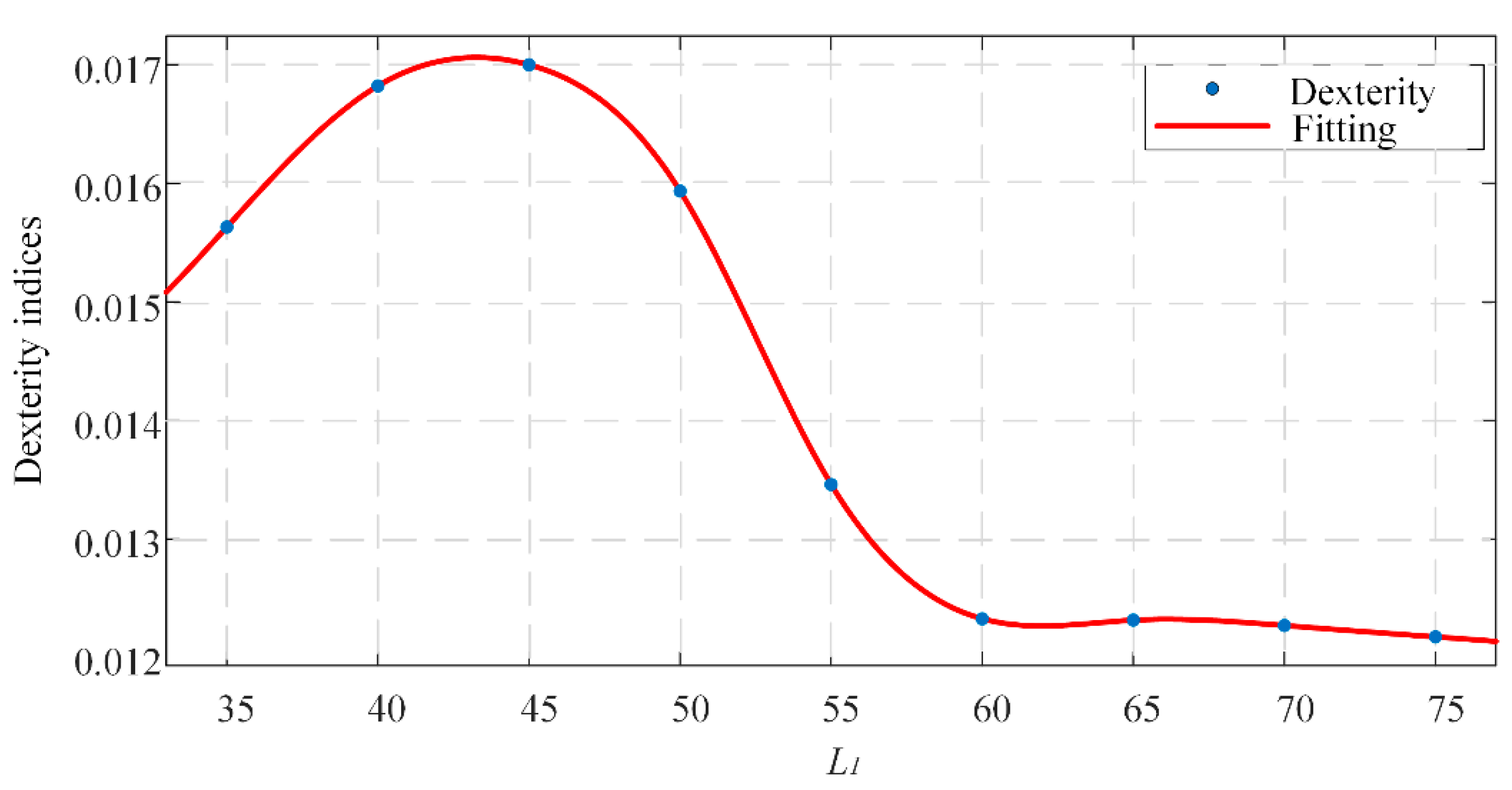
| Total Length | Length of the NCR Part | Length of the TCR Part | k of the TCR Part | Global Dexterity | |
|---|---|---|---|---|---|
| CCR | 100 | 50 | 50 | π/100 | 0.0159 |
| CTR | 100 | - | 50–50 | π/100 | 0.0108 |
| Segment 1 | Segment 2 | Dexterity Index (DI) | ||||||
|---|---|---|---|---|---|---|---|---|
| θ1/rad | φ1/rad | L1/mm | L2 (mm) | φ2/rad | k/(rad/mm) | |||
| Group 1 | [0, θg1] | [0, 2π] | 35 | [0, 65] | [0, 2π] | π/100 | 0.0156 | |
| Group 2 | [0, θg2] | [0, 2π] | 40 | [0, 60] | [0, 2π] | π/100 | 0.0168 | |
| Group 3 | [0, θg3] | [0, 2π] | 45 | [0, 55] | [0, 2π] | π/100 | 0.0170 | |
| Group 4 | [0, θg4] | [0, 2π] | 50 | [0, 50] | [0, 2π] | π/100 | 0.0159 | |
| Group 5 | [0, θg5] | [0, 2π] | 55 | [0, 45] | [0, 2π] | π/100 | 0.0135 | |
| Group 6 | [0, θg6] | [0, 2π] | 60 | [0, 40] | [0, 2π] | π/100 | 0.0123 | |
| Group 7 | [0, θg7] | [0, 2π] | 65 | [0, 35] | [0, 2π] | π/100 | 0.0123 | |
| Group 8 | [0, θg8] | [0, 2π] | 70 | [0, 30] | [0, 2π] | π/100 | 0.0123 | |
| Group 9 | [0, θg9] | [0, 2π] | 75 | [0, 25] | [0, 2π] | π/100 | 0.0122 | |
Publisher’s Note: MDPI stays neutral with regard to jurisdictional claims in published maps and institutional affiliations. |
© 2022 by the authors. Licensee MDPI, Basel, Switzerland. This article is an open access article distributed under the terms and conditions of the Creative Commons Attribution (CC BY) license (https://creativecommons.org/licenses/by/4.0/).
Share and Cite
Zhang, G.; Du, F.; Xue, S.; Cheng, H.; Zhang, X.; Song, R.; Li, Y. Design and Modeling of a Bio-Inspired Compound Continuum Robot for Minimally Invasive Surgery. Machines 2022, 10, 468. https://doi.org/10.3390/machines10060468
Zhang G, Du F, Xue S, Cheng H, Zhang X, Song R, Li Y. Design and Modeling of a Bio-Inspired Compound Continuum Robot for Minimally Invasive Surgery. Machines. 2022; 10(6):468. https://doi.org/10.3390/machines10060468
Chicago/Turabian StyleZhang, Gang, Fuxin Du, Shaowei Xue, Hao Cheng, Xingyao Zhang, Rui Song, and Yibin Li. 2022. "Design and Modeling of a Bio-Inspired Compound Continuum Robot for Minimally Invasive Surgery" Machines 10, no. 6: 468. https://doi.org/10.3390/machines10060468
APA StyleZhang, G., Du, F., Xue, S., Cheng, H., Zhang, X., Song, R., & Li, Y. (2022). Design and Modeling of a Bio-Inspired Compound Continuum Robot for Minimally Invasive Surgery. Machines, 10(6), 468. https://doi.org/10.3390/machines10060468