Abstract
Current and conventional pose (position and orientation) control of a small underwater vehicle is achieved by using rudders (yaw motion control) and elevators (pitch motion control), but these suffer from non-linear, indirect and complex control issues. This paper proposes an innovative pose control mechanism for small underwater vehicles. The mass shifter mechanism is designed and fabricated to control pitch and yaw motion with a single propeller only. The center of mass of the underwater vehicle is altered by moving a pair of counterweights on fixed tracks. The pitch and yaw are achieved by controlling the position of the counterweight pairs. The proposed system is designed, fabricated and tested in a real underwater environment for proof-of-concept. The result shows a simpler, more efficient and more effective pose control mechanism than conventional technology.
1. Introduction
Autonomous underwater vehicles (AUVs) are one type of unmanned underwater vehicle. The major unmanned underwater vehicles can be classified into three categories as below. The first category is the remotely operated vehicle (ROV). An ROV is a tethered underwater vehicle. ROVs are connected to a platform or the deck of a ship on the sea. An ROV is usually operated by people on board or in the sea, and so it has high mobility. ROVs are usually used for surveying fishes [1,2]. An ROV may be towed behind a vessel or ship with a towing cable of a certain length. It usually carries some sensors, sonars, or receiving devices to collect the underwater data. The second category is the AUV. AUVs are usually programmable. They are usually equipped with several sensors to measure temperature, salinity, depth and other underwater data. They can travel underwater without real-time operation by a person. The third category is the autonomous underwater glider, also known as an ocean glider or sea glider. It is an underwater vehicle driven by gravity and buoyancy. It achieves a stable state by changing the interaction between gravity and buoyancy. The shape is usually designed to be streamlined with low resistance, with an extremely small amount energy needed to move through the water. The SOEST groups that operate and/or use ocean glider data include C-MORE, HOT and PacIOOS [3]. Ocean gliders are highly suitable for undercurrent and deep-sea survey [4,5].
Underwater vehicles have become popular devices for investigating the conditions and substances below the water’s surface in scientific and fishery applications due to the significant improvement in modern technology. The innovative SyPRID sampler was used to collect plankton at a depth of about 6000 m [6]. It can cooperate with the Sentry AUV to obtain a pair of large-volume plankton samples at a specified depth and measurement line. A high-resolution autonomous sensor was equipped on an AUV vehicle to collect physical, chemical and biological data to identify bioluminescent dinoflagellates and zooplankton and investigate their living environment [7]. Another example of an AUV application is their use for tracking marine animals tagged with individually coded acoustic transmitters, which demonstrated the advantages of AUVs in tracking underwater targets. The nature of the fluid in an environment influences the hydrodynamic performance of an AUV [8].
Since an AUV operates underwater, the drag force of the environmental fluid influences the travelling and steering of the AUV. A two-phase computational fluid dynamics method was applied in the evaluation of hydrodynamic performance of an axisymmetric AUV. The wave heights, Reynolds numbers, and submerged depths of the AUV influenced the drag of the AUV significantly [9]. A mathematical model of hydrodynamics was applied in the calculation of the influence of the wall in realizing the precise control and maneuverability of a complex-shaped underwater vehicle [10].
A method to save space for an underwater glider in steering with a small pitch angle was also presented. For rudderless underwater gliders, steering with a small pitch angle increases the steering angle and reduces the distance needed to complete an expected steering by a gravity center adjustment module, as in [11]. The elevator and rudder mechanism will increase the complexity of the design of the leak-proofing of the AUV frame. Therefore, there are some studies on the use of rudderless designs to control the yaw and pitch angle of underwater vehicles. One patent deploys at least two discharge nozzles for water jet flow as the main thrust of an underwater vehicle [12]. It changes the balance of water flow to cause a difference in thrust on the two side. This change produces the momentum of the AUV to change the yaw. As another way to change the yaw of underwater vehicles, a synthetic jet was presented to steer an AUV, as in [13]. A buoyancy control system was also presented for underwater vehicles, which mainly includes a working chamber, a piston, and fluid [14]. It controls the piston to move the fluid inside and outside to change the center of gravity and change the pitch angle of the AUV. A mass shifter mechanism (MSM) of an AUV can be also operated to change the yaw and pitch angles by means of a single set [15]. The MSM is a feasible mechanism to control AUV motions. A systematic study of an MSM inside an AUV platform was reported [16].
Underwater gliders are a category of underwater vehicle without external active propulsion systems. The study of trajectories is also an important area of AUV research. Trajectory studies can help to evaluate the performance of underwater gliders. A glider coordinated control system using a complex glider model and a simple particle model for prediction and planning to steer a fleet of underwater gliders to a set of coordinated trajectories was presented [17]. Path planning and trajectory optimization are also important areas of study. Optimal path planning for AUVs assigned several targets by means of a 3D Dubins curve was presented. These path-planning problems were modeled as the Multiple Traveling Salesman Problem and Genetic Algorithm to obtain the optima [18]. The AUV can perform horizontal movement, a pitch angle, and diving motion by changing the center of gravity of underwater vehicles that can be manned or unmanned, self-powered or dragged by an external power, and remotely controlled or autonomous. It includes algorithms and the sensing of the surrounding environment. The trajectory planning of AUV is discussed in order to achieve the set target [19,20,21]. The stability of the AUV algorithm and control systems is the key index for the AUV to travel, aligning the planned trajectories efficiently. On the other hand, in order to navigate the AUV according to the planned path, it is also important to use sensors and image recognition equipment attached to the AUV to locate it effectively and correctly.
Although many types of sensors are candidates to detect the surroundings of an AUV, sonar is one of the most common sensors equipped in AUV. Sonar is one of the most popular devices used to avoid obstacles and to describe the surroundings of AUVs. Refs. [22,23,24] present the applications of sonar in underwater vehicles. Considering the ambient conditions of an AUV’s operation, it is operated under the water where the electrical wave is almost impossible to penetrate. When using sensors such as an IMU as a device for underwater positioning, the signal noise will cause progressive errors and make the positioning inaccurate. A Kalman filter is often used for noise removal in AUV sensors, as in [25,26,27]. Cameras are also often used in the sensing system of underwater robots. A combination of cameras and ultrasonic sensors are used for underwater robotic fish object tracking and obstacle avoidance, as in [28]. The docking of AUVs can help applications in the underwater routine cruising of AUVs, as in [29]. Two cameras are used for AUVs to sense the environment in the docking process. A binocular vision algorithm in distance measurement was proposed by using two cameras for AUV docking, as in [30]. ROV with camera for real-time video capture can be equipped with other integrated sensors measuring hydrological data and software with machine vision algorithms for specific underwater survey mission purposes, as in [31].
The objective of this research is to establish a prototype using the mass shifter mechanism as a steering control method for AUV. Referring to the research results of [11,15], two sets of MSMs by using ball screws to move the mass blocks to change the center of mass of the AUV are used. This AUV is established to experiment on and verify the feasibility of the MSM method for AUV direction control. This study seeks to apply the basic mechanism and dynamic theory of the direction control of this new control method of AUVs. The purpose of this research is to develop a new control method for underwater vehicles with cruise purposes, not for fixed-location vehicles. Having no rudders and elevators on an AUV avoids there being gaps on the body of the underwater vehicle. The control method used in this study is not intended to replace the traditional methods of controlling a AUV without a rudder and elevator. This will provide AUVs with a new control method. CAD software is used to create models to simulate design concepts and select suitable parts. According to the CAD simulation results, the selected parts are combined and connected to the control circuit. Finally, the feasibility of the new control method is verified by prototype design through certain tests.
2. Materials and Methods
AUV-related disciplines and research include many fields. Due to the different application conditions and the purpose of use, there are also multiple different types of underwater vehicle to meet the requirements of different usages. In addition to underwater vehicles used in offshore or fixed-point waters, AUVs that can cruise through the sea for a long time to search for specific targets also represent a research direction in recent years. Regarding these purposes, it is important for underwater vehicles to have high levels of watertightness. This is a research direction required for underwater vehicles to cruise in deeper waters for a longer time. Obtaining a simpler structure to avoid hooking obstacles in the water is also important.
2.1. Overview
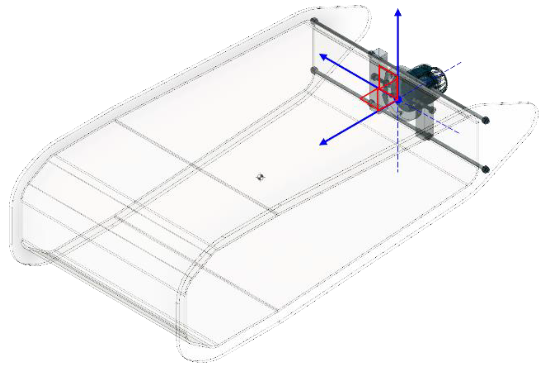
The center of mass in the AUV is aligned with the three perpendicular axes of X, Y and Z. A right-handed coordinate system is used, as in Figure 1. The X-axis is parallel to the AUV axial direction. The positive X direction is from the mass center of the AUV toward its nose. Surge is a conventional name used for the rotation around this axis. The Y-axis is perpendicular the AUV’s axial direction. The positive Y direction is from the mass center of the AUV to the left-hand side. A rotation around this axis is usually called sway. The Z-axis is perpendicular to both the X-axis and Y-axis following a right-handed orientation system. The positive Z direction is from the mass center of the AUV to above the AUV.
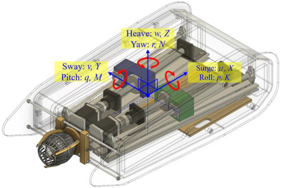
Figure 1.
Coordinate system of applied field.
A mass shifter mechanism system is deployed inside the AUV to achieve the steering, surfacing, and diving process. The forces acting on the movable mass are the weight of the movable mass P, normal force FN, total frictional force Ff, and force of the servo motor Fm [10]. In Figure 2, it is assumed that the movable mass is moving towards the stern of the vehicle with speed and the vehicle pitches up from a horizontal position at a pitch angle θ. Because friction always acts in a direction opposite to the speed, the direction of the total frictional force Ff is towards the bow of the vehicle. The weight of the movable mass could be resolved into two components at right angles to each other, P1 and P2. P1 is parallel to the mass shifter moving direction and P2 is perpendicular to P1. FN and P2 become balanced. FN is the force exerted on the movable mass by the screw shaft. In terms of the equivalent movable mass, me, and the acceleration, ae, the equilibrium equation describing the dynamics of the mass shifter mechanism is as in (1).
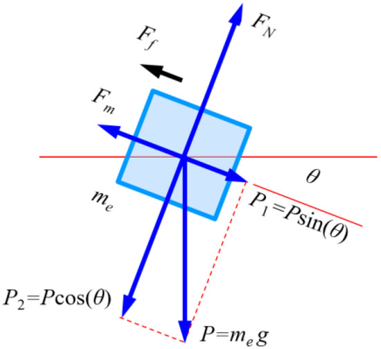
Figure 2.
Forces on the mass shifter mechanism.
The coordinate frame consists of three parts: the inertial frame, body frame, and current frame, as in [6]. The inertial frame E0 (i, j, k) is identical to the Earth. The position and attitude of AUV are described as P = [x, y, z]T and A = [ϕ, θ, ψ]T, respectively. The body frame e0 (xb, yb, zb) is identical to the AUV itself. It is established at the buoyancy center. The translational and angular velocities in the body frame are as V = [V1, V2, V3]T and Ω = [p, q, r]T, respectively. In addition, the hydrodynamics are calculated in the current frame π0 (π1, π2, π3), which is obtained from the body frame by rotating around yb by the attach angle and rotating around zb by the sideslip angle. The change rate of P is expressed as in (2). With notations c = cos(.) and s = sin(.), RBE is expressed as in (3). The relationship between A and Ω is expressed in (4).
2.2. Mechanical Design Architecture
An AUV design concept is proposed in this study. The underwater vehicle in this study with MSM was fabricated to verify this new concept for a rudderless design of an AUV. There are five major potions in the underwater vehicle in this study, including the outer hull, motor, propeller, electronic control system, batteries, and mass shifter mechanism. The buoyancy of the AUV is designed to be slightly greater than its weight, and therefore the AUV will float to the water’s surface in the case of power loss.
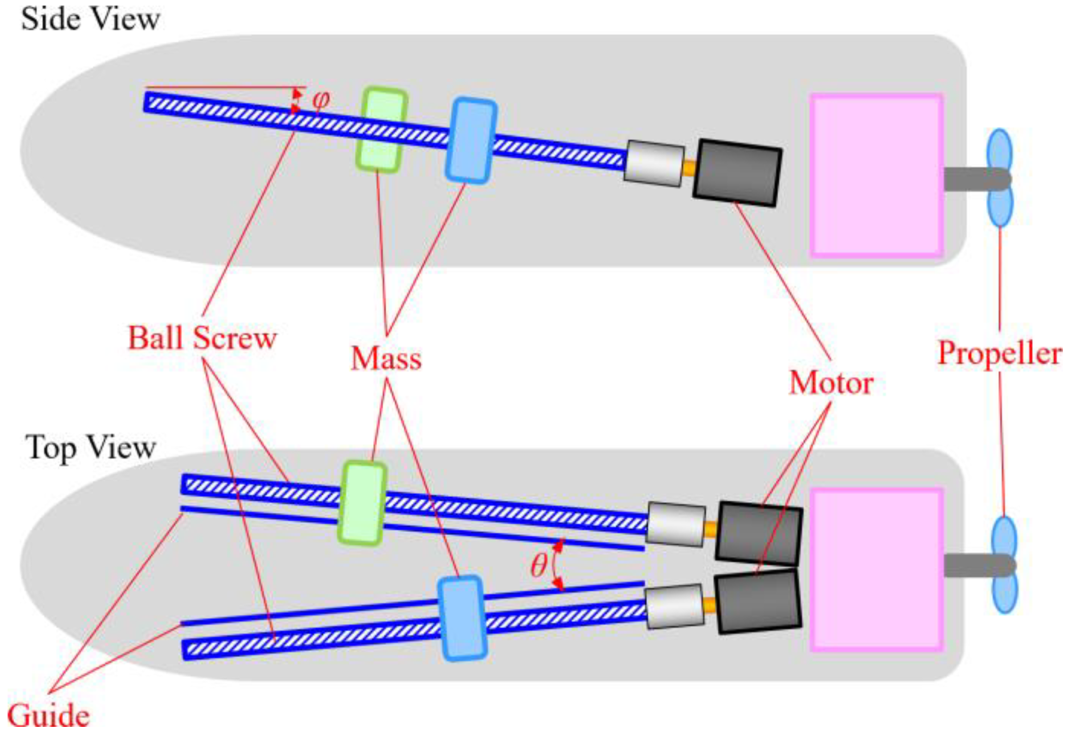
In this study, a simple gyroscope and e-compass were deployed. More accurate sensors are recommended for the next stage of study for better feedback regarding the status of the AUV. With a single propeller and mass shifter mechanism inside the AUV hull, the AUV can perform horizontal and vertical motion. It also controls the pitch angle and depth motion with this inside MSM, which changes the center of gravity of the AUV. This mass shifter mechanism is designed with two linear motion ball screws driven by step motors and two movable brass blocks as counterweights, as shown in Figure 3.

Figure 3.
Mass shifter mechanism design.
In this design, MSM is used for directional control. This control method uses two counterweights to make displacements, so that the overall center of gravity changes. After the center of gravity changes, the resultant force and torque will cause the AUV to be affected by the system. The posture changes to achieve the purpose of changing the direction of travel. When the two counterweights go forwards or backwards, the center of gravity of the AUV also shifts forwards or backwards, and right or left. These shifts change the resultant forces and torque on the AUV. Due to the AUV’s propulsion by the thruster, it will be propelled downward, or upward, or to right, or to left, respectively. The resultant forces and torque of the counterweights’ positions and AUV’s motions are listed on Table 1.

Table 1.
Resultant forces and torques for UV directions.
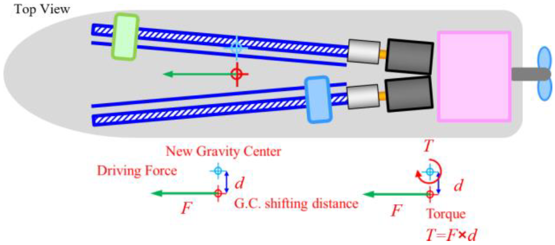
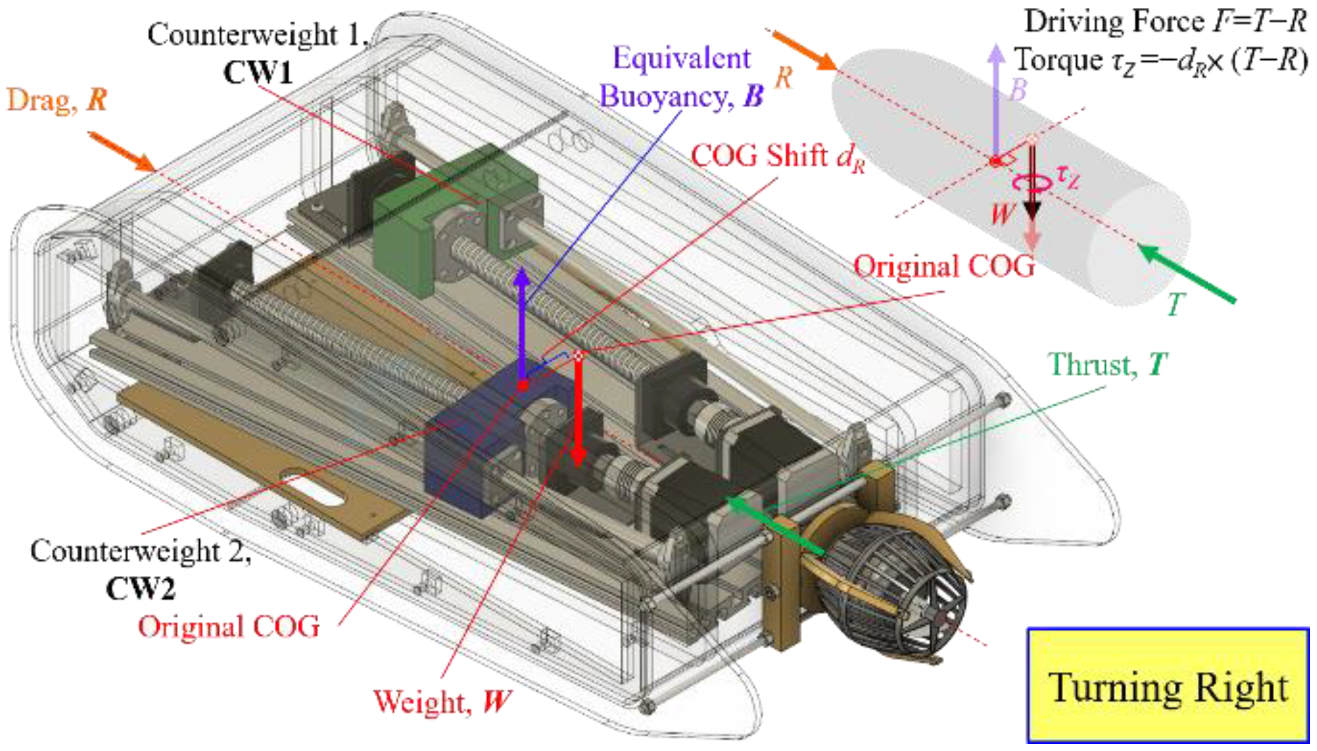
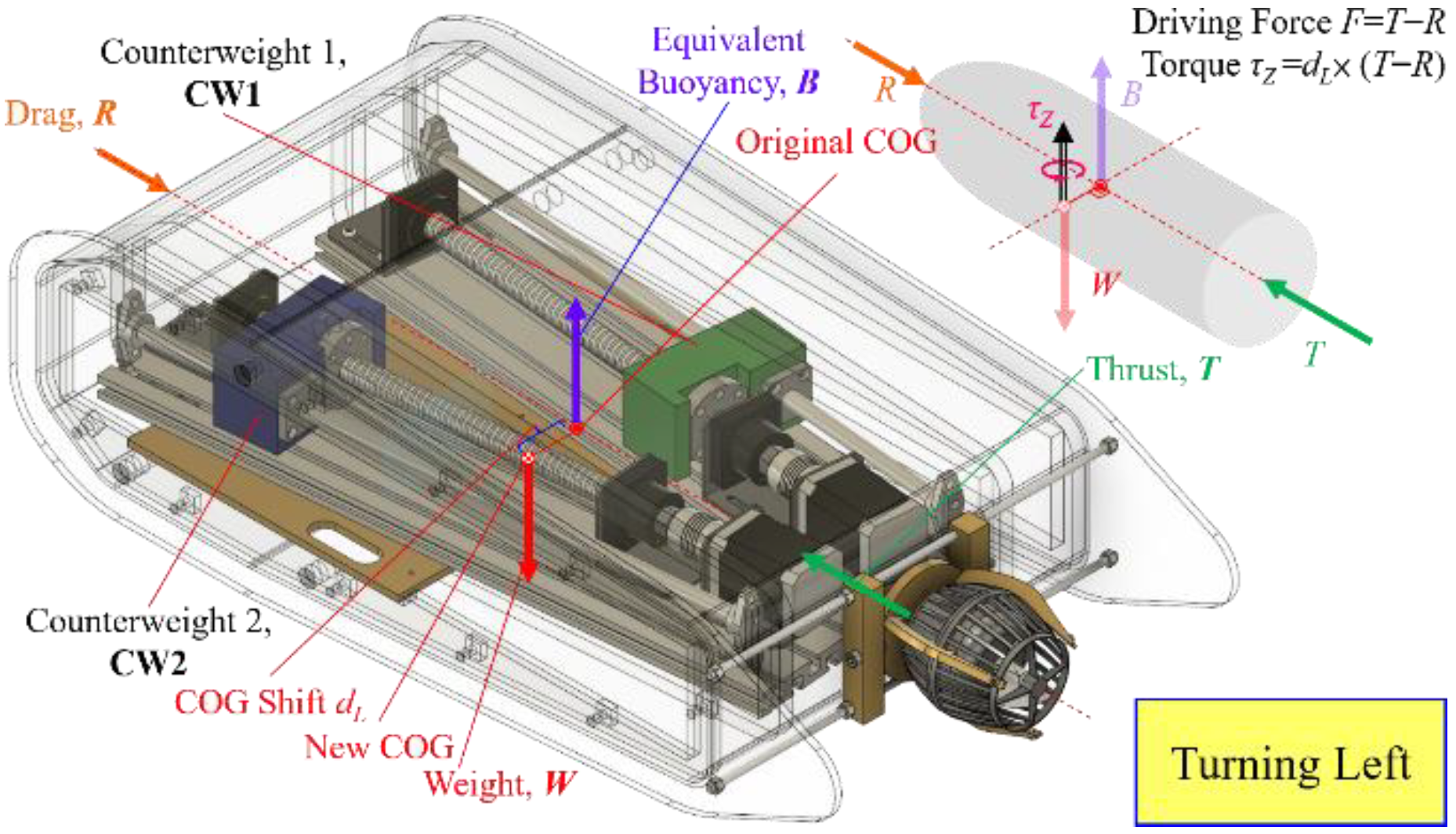
The steering control algorithm seeks to achieve the yaw angle. The AUV design causes torque on the vehicle using the mass shift in the steering process. The center of gravity (COG) will shift a distance d from the original COG and perpendicular to the X axis. The equivalent driving force F still applies on the original COG and will cause a torque τ on the new COG. It will cause a steering force to be applied on the AUV. In Figure 4, a diagram for the equivalent force and momentum for steering control of MSM is presented. Figure 5 and Figure 6 show the counterweights’ configuration for turning right and turning left. One counterweight moves forward and the other moves backward, and the vertical angle remains the same.

Figure 4.
Momentum of steering.
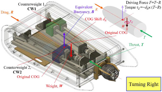
Figure 5.
MSM configuration for turning right.
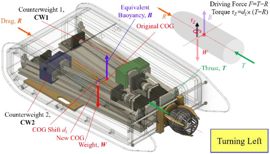
Figure 6.
MSM configuration for turning left.
The equivalent driving force F and unbalance buoyance on the new COG cause a torque T on the new COG, as in Figure 6. The one mass moves forward and one moves backward at the same time. Additionally, the AUV will turn with an angular velocity and AUV will perform a turn. In Figure 5, the right mass moves forward and the left mass moves backward, and the AUV buoyance on the new COG causes a torque T on the new COG, as in Figure 6. One mass moves forward and one moves backward at the same time. Additionally, the AUV will turn left with an angular velocity.
2.3. Mass Shifter Mechanism for Surfacing and Diving
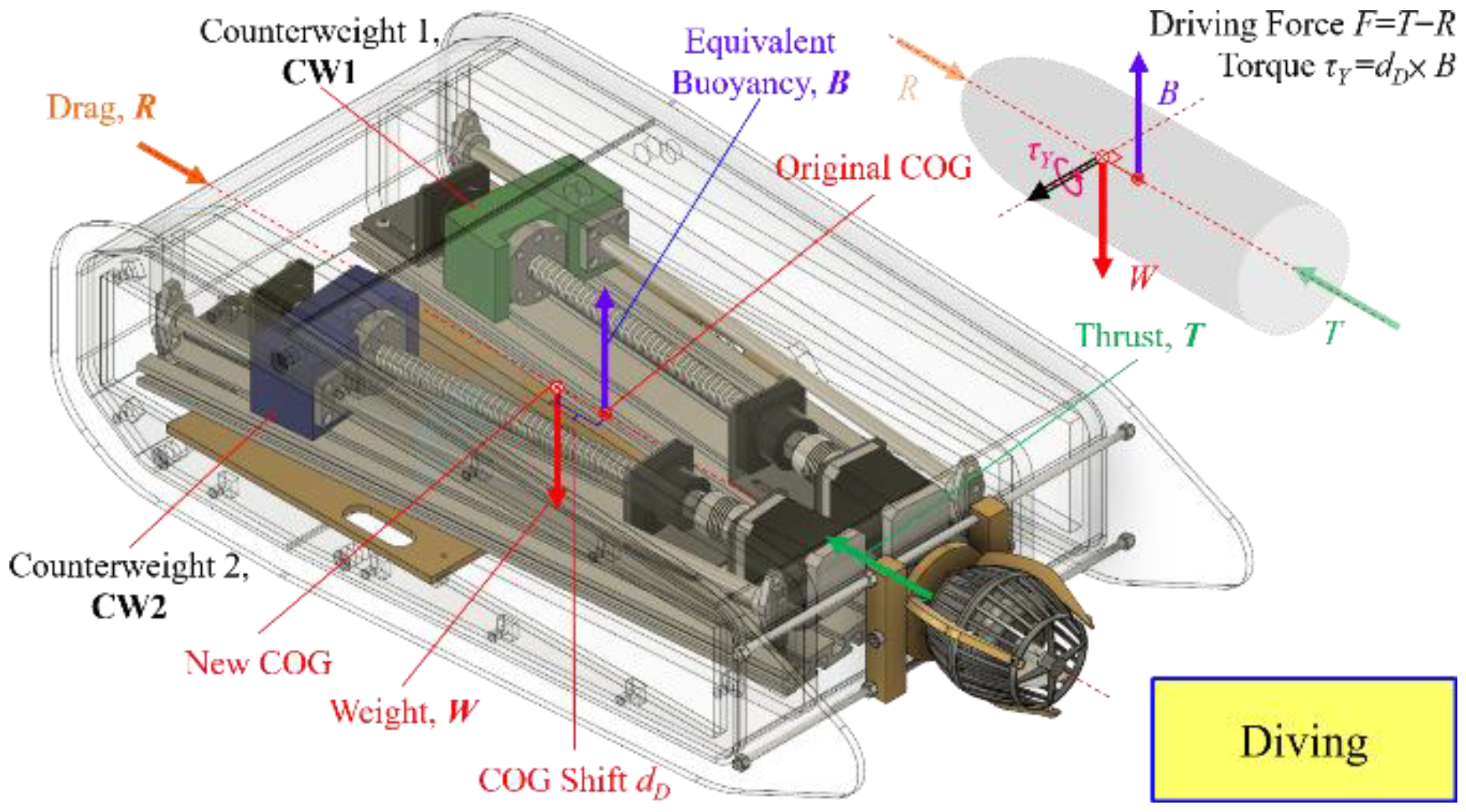
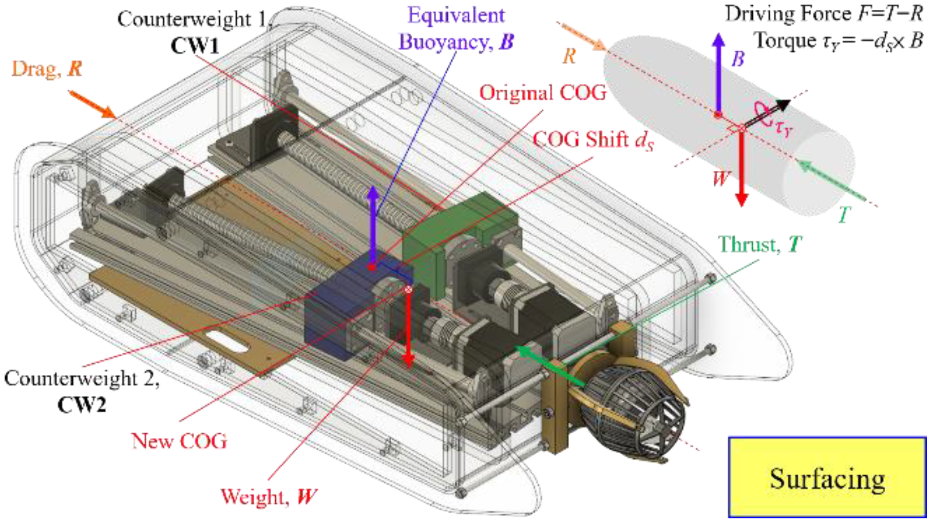
Surfacing and diving control algorithm is to change a resultant force on the AUV. The forces acting on AUV are as COG will shift a distance d from original center of gravity and perpendicular to the Y axis from the natural status as in Figure 7. The equivalent driving force F and unbalance buoyance on the new COG cause a torque T on the new COG as in Figure 8, the two masses move forward together and the underwater vehicle bow will depress by a certain angle and the underwater vehicle will dive. For surfacing, a similar action is used but in different direction of movement for the MSM. In Figure 9, the two masses move backwards together and the underwater vehicle will depress by a certain angle and the underwater vehicle will dive.
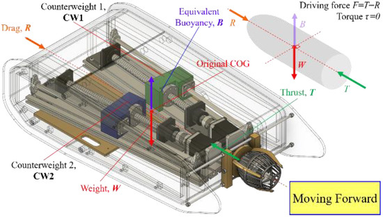
Figure 7.
MSM in natural status.
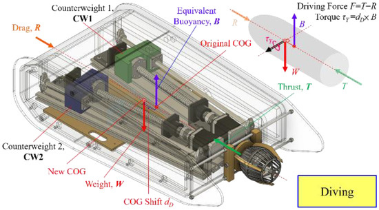
Figure 8.
MSM action for diving.

Figure 9.
MSM action for surfacing.
2.4. Computer Aided Design for Mechanical Configuration
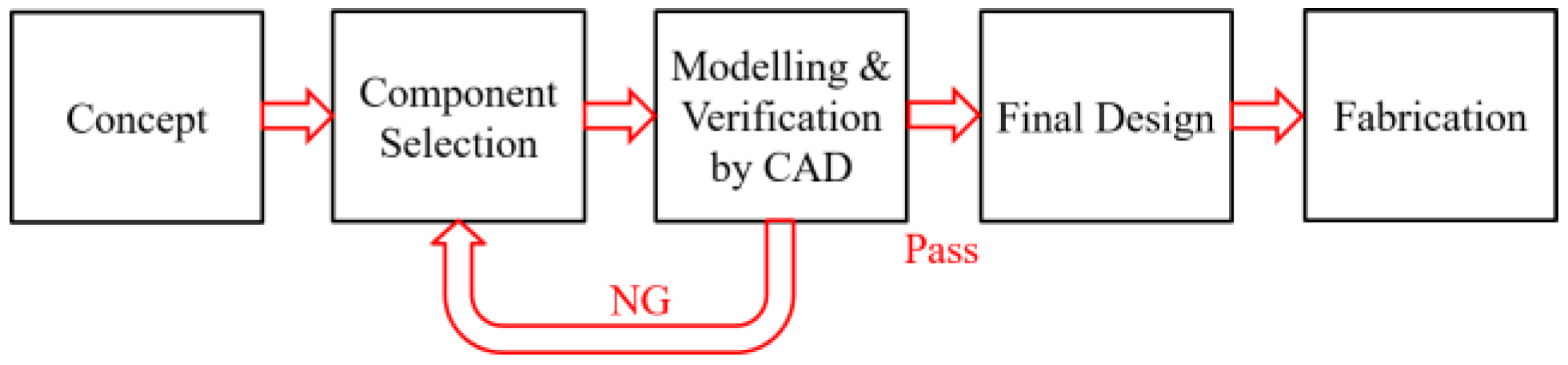
In this research, we used Fusion 360 as the CAD software. In addition to the CAD function, the software also has the preliminary CAE functions including volume, mass, and center of gravity, which is helpful for design reference. In this study, the design process is shown in Figure 10. Mainly based on the concept of design, we selected the relevant component combination, and then used Fusion 360 to model and combine the deployment mechanism to verify. After verifying the 3D model of design in CAD software and all key points were passed, we completed the design and implemented it accordingly.
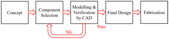
Figure 10.
Design flow chart for mechanical potion.
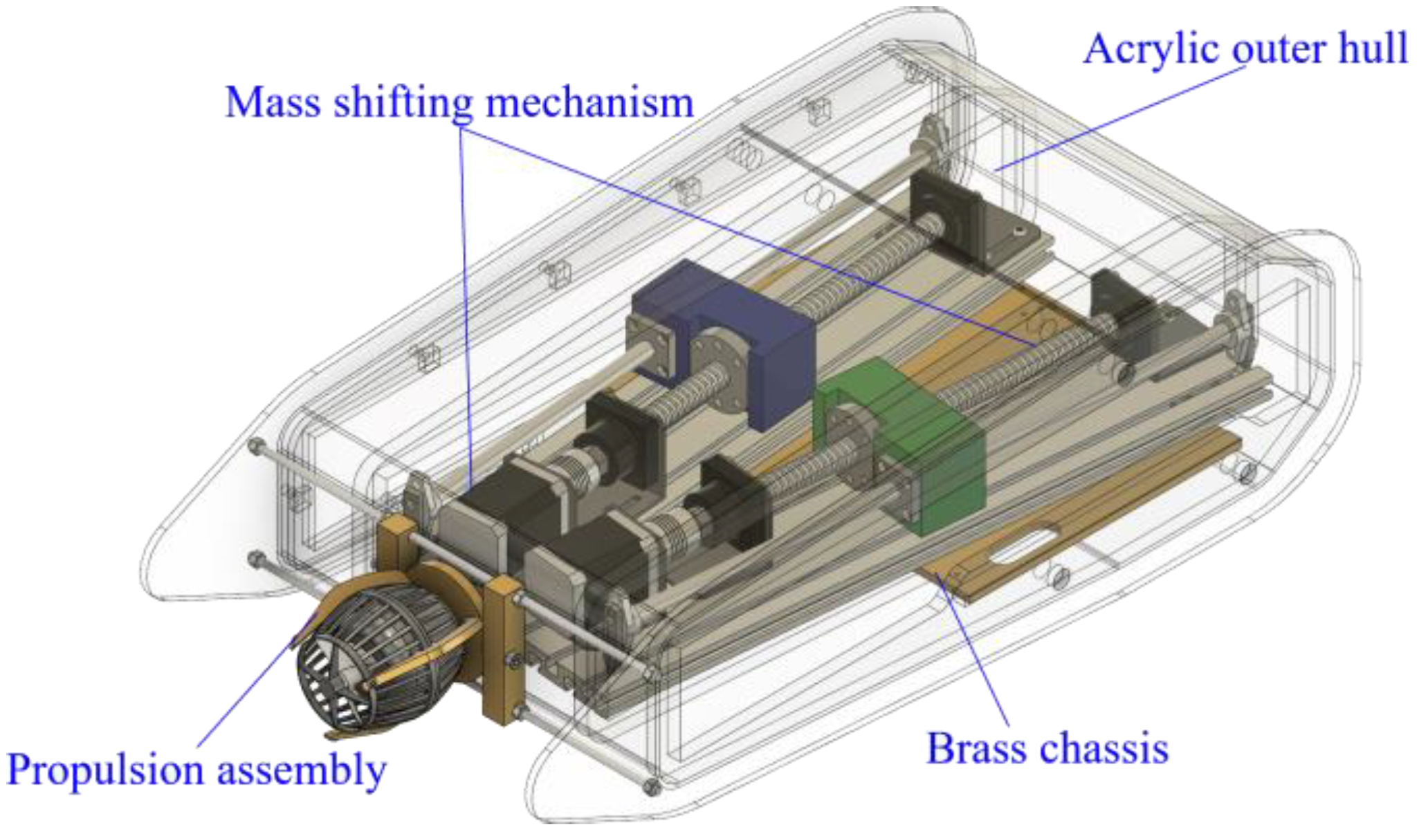
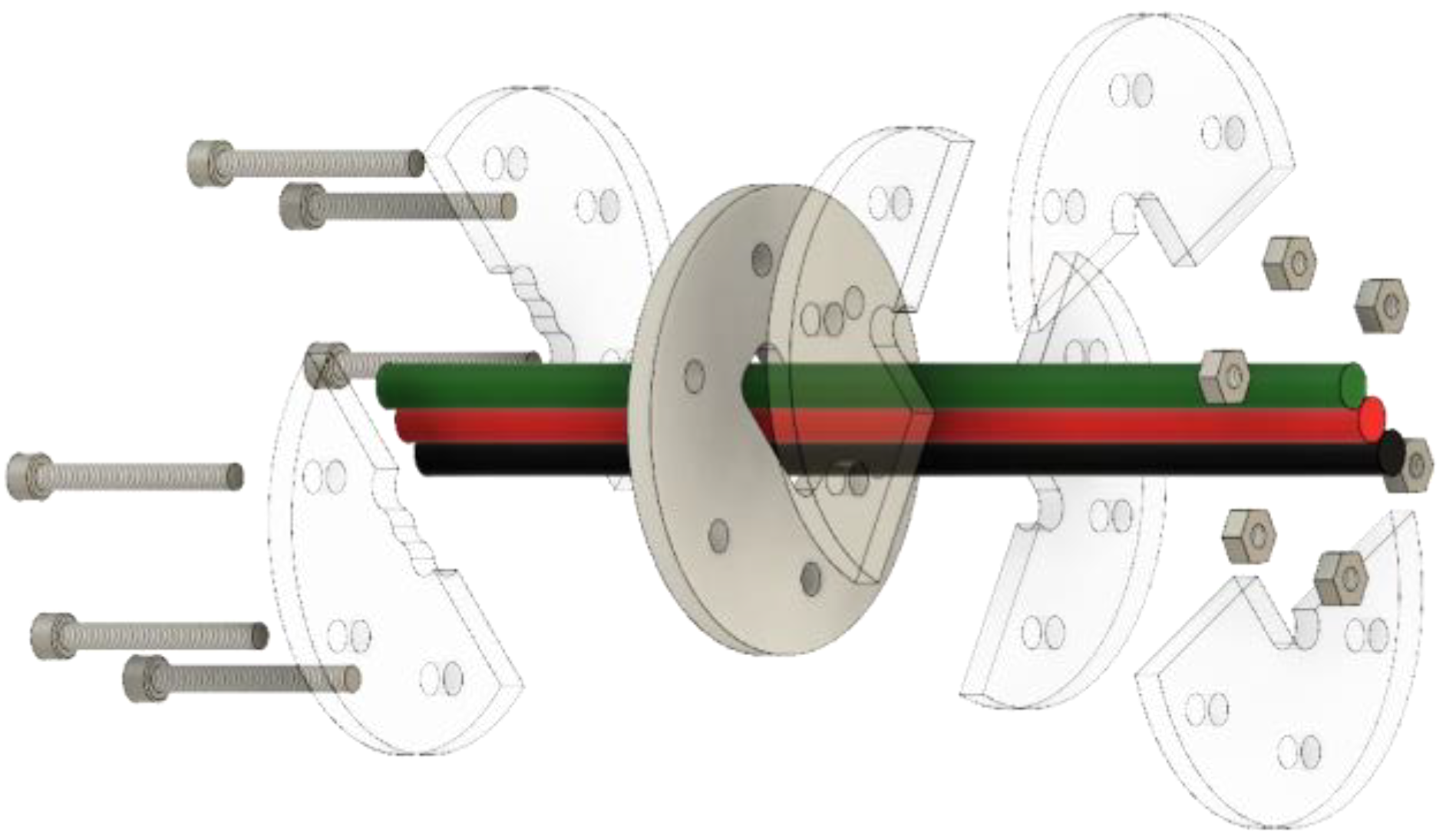
There were four major mechanical portions in the underwater vehicle in this study, including the outer hull, propulsion assembly, MSM, and brass chassis, as in Figure 11. The outer hull was made of acrylic, combined with silicone film, or cured silicone adhesive as a waterproof material. The propeller assembly was a combination of brass parts and stainless-steel screw threads to fix the propeller motor. The MSM included a ball screw, stepper motor, and counterweight to generate the displacement of mass center. For the brass chassis, there were many screw holes on it to fix the MSM to the acrylic housing. The mass shifter mechanism was deployed in the underwater vehicle in this study, as in Figure 12.

Figure 11.
Four major mechanical portions of the AUV in this study.

Figure 12.
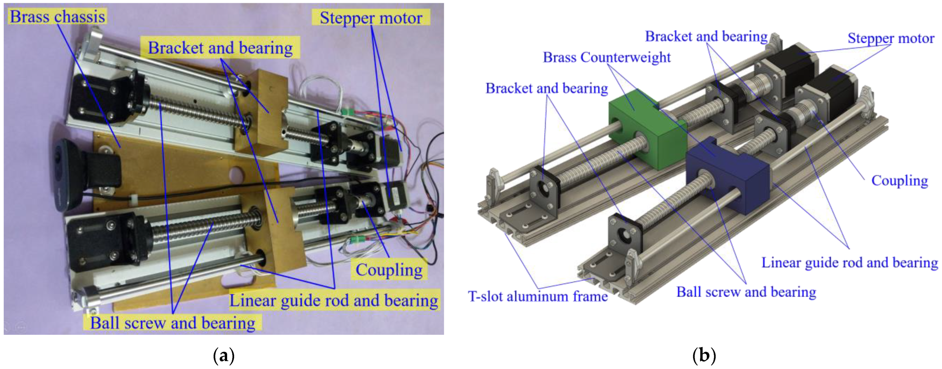
Mass shifter mechanism of the underwater vehicle in this study: (a) actual; (b) CAD model.
The couplings connected stepper motors and ball screws. The brass counterweights were fixed to spiral ball bearings and linear bearings. The ball screws and the linear guide rods were combined with the mass forming block on the T-slot aluminum frame via the brackets. There were two sets of symmetrical mass moving combinations in the mass shifting mechanism fitted onto the brass chassis at an angle, and when the stepping motor rotated forward or in reverse, the mass was advanced or retracted. Since the two mass moving combinations had an angle, when one mass moved one forward, the other moved backwards. Then, the mass was produced near the Y axis or away from Y, or the mass moved forward or backward at the same time, thereby causing the center of mass of the body to change.
2.5. Propulsion Assembly
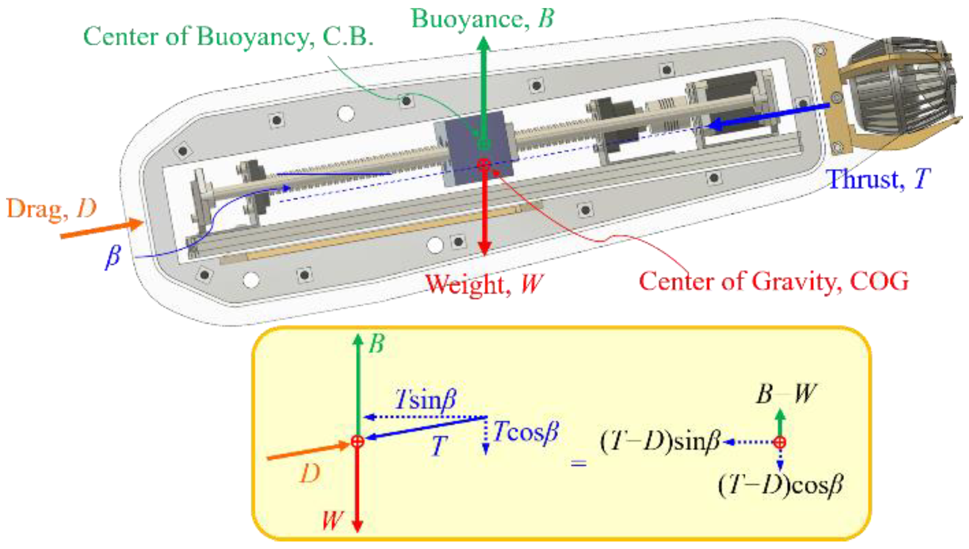
In the underwater vehicle in this study, the propulsion assembly includes a propeller, motor, and adjustable bracket. To adjust the direction of the thrust T of the propeller, we divide it into upward and downward component forces, as in Figure 13. The resultant forward component force deducting the drag force D is the net thrust driving the underwater vehicle in this study forward. The downward component force is approximately equal to the buoyancy B minus the gravity W. It allows the underwater vehicle in this study to travel underwater after the diving process. To achieve this purpose, the adjustable brass bracket is used to adjust the motor and propeller, as in Figure 14. The motor and propeller are screwed to the adjustable brass bracket. After adjusting the motor and propeller to an appropriate angle, we fastened the screw to fix the thruster direction. As the impulse-momentum theorem states, the change in momentum of an object equals the impulse applied to it. The equation is as in (5).
where F is the thrust of propulsion, Δt is the contact time, m is the mass and Δv is the change in velocity
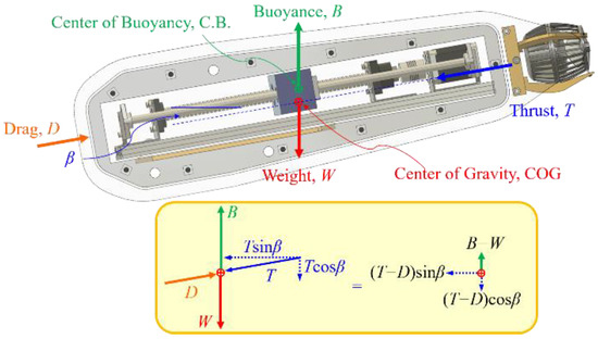
Figure 13.
Free-body diagram of the underwater vehicle in this study.
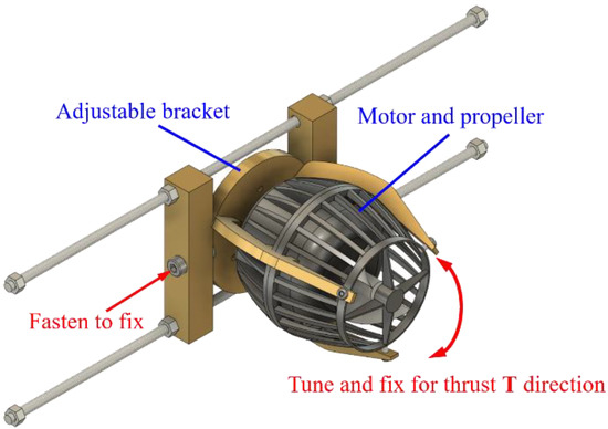
Figure 14.
Adjustable propeller and bracket.
2.6. Hull Design
From the perspective of fluid mechanics, the resistive force acting in the opposite direction to an object moving inside a fluid is called the drag force. The drag force depends on the velocity of the object. The traditional expression of drag force FD is as in (6). The drag coefficient CD is a dimensionless number and depends on the shape of the object and Reynolds number of the fluid surround the objects. Regarding the shape factor, the drag coefficient of an object moving inside a fluid is mainly related to skin friction and form drag. Based on the principle of fluid mechanics, the drag coefficient is greatly related to the shape of the object. The drag coefficient of a streamlined object is the smallest, and followed by a sphere, half-sphere, and cone. The drag coefficients of a short cylinder and cube are the largest, as in Figure 15.
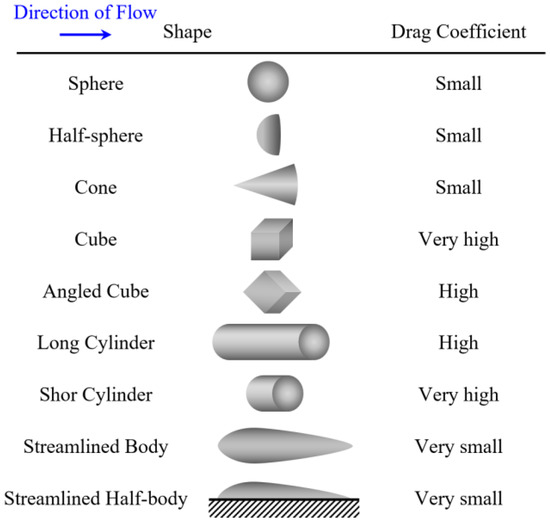
Figure 15.
Effects of measured drag coefficients.
Considering the current fabrication process of acrylic hulls, our underwater vehicle cannot be produced as a completely streamlined appearance. The shape of the new underwater vehicle was designed to be as close to a streamlined shape as possible, and we designed the fins on the sides of hull to maintain balance and prevent tilting.
where ρ is the fluid density, v is the velocity of the object relative to the fluid, A is the cross-sectional area of object. Referring to the drag coefficient of common shapes in Figure 15, the streamlined design has low drag. The hull of the underwater vehicle in this study is designed to be as close to a streamlined shape as possible. Considering the fabrication of the acrylic hull, some planes are designed for better manufacturing accuracy.
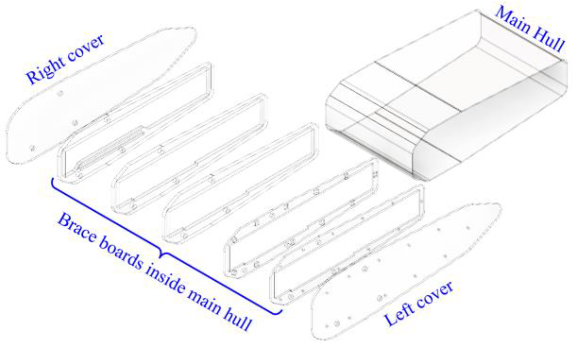
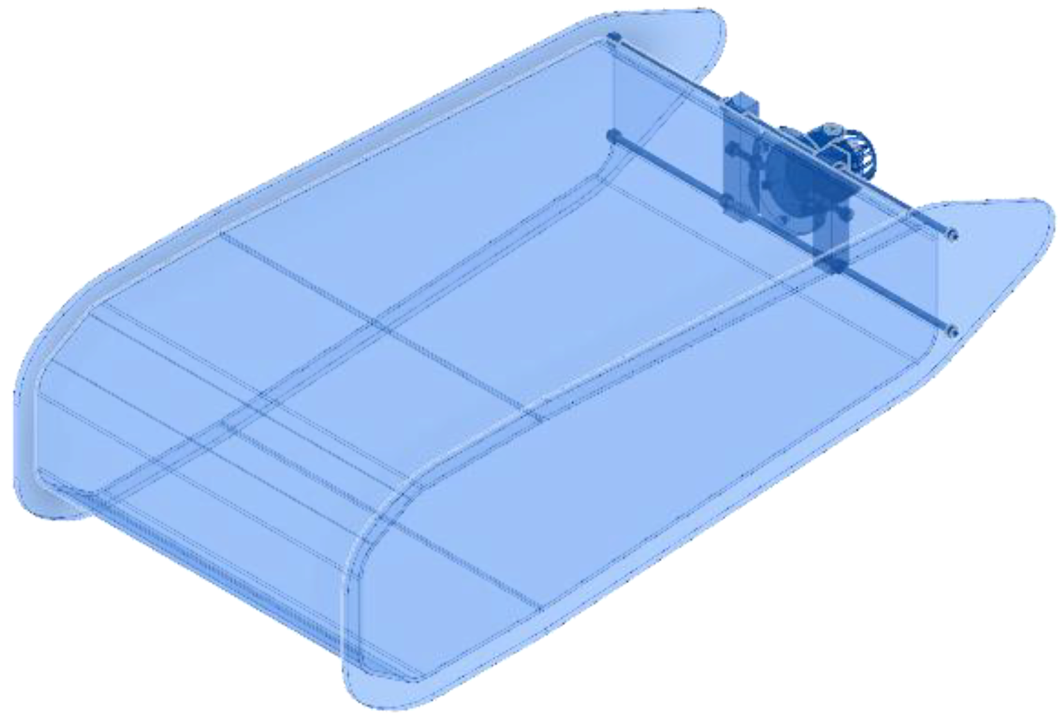
Five pieces of laser-cut and calibrated acrylic panels are designed to support the MSM and other items that drive the mechanism, as in Figure 16. We used the CAD software to create a 3D model of the underwater vehicle and calculated the volume, as in Figure 17. According to the Archimedes principle, the buoyancy of an object completely or partially immersed in a liquid at rest is subjected to the weight of the volume the object displaces. The location of the buoyancy center is the same as the center of gravity of the fluid weight of the volume displaced by this object, and it is equivalent to the pressure difference results in a net upward force on the object. The forces of pressure on an object immersed in liquid are distributed across the object’s surface. According to the statics theory, all forces can be combined into a net force buoyancy acting on the center of buoyancy. The upward buoyancy force on an object acts through the center of buoyancy, being the geometric center of the displaced volume, as in Figure 18. An object immersed in a fluid is stable if it tends to restore itself to an equilibrium position when the COG and center of buoyancy are collinear in the Z axis direction and the former is below the latter.
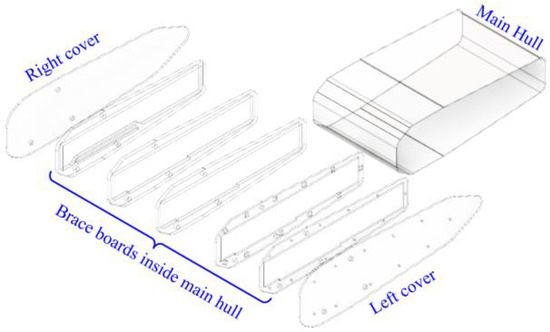
Figure 16.
Exploded-view drawing for acrylic.
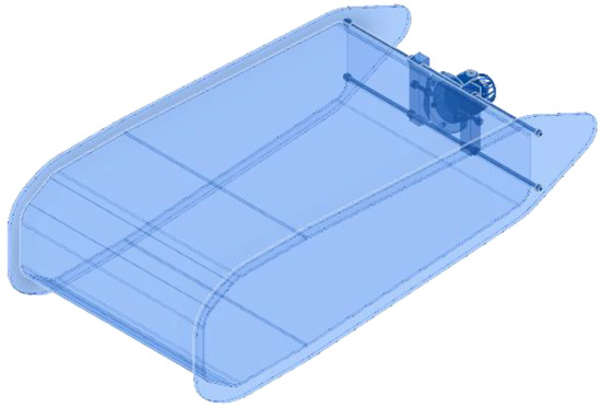
Figure 17.
Computer simulated volume of underwater vehicle.
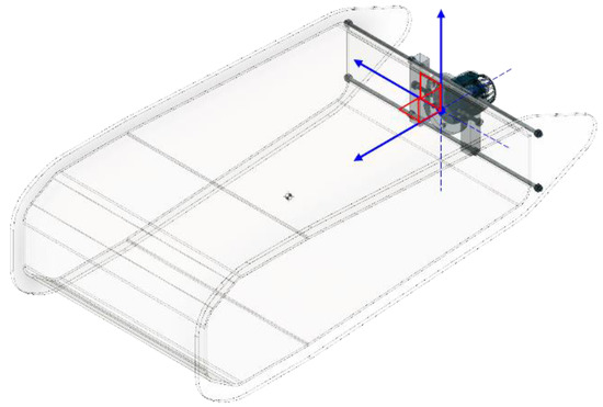
Figure 18.
Buoyancy center and coordinate system.
We used the CAD software to create a 3D model of the underwater vehicle in this study and calculated the volume. According to the Archimedes principle, the buoyancy of an object completely or partially immersed in a liquid at rest is subjected to the weight of the volume the object displaces. The location of the center of buoyancy is the same as the center of gravity of the fluid weight of the volume displaced by this object, and it is equivalent to the pressure difference results in a net upward force on the object. The forces of pressure on an object immersed in a liquid are distributed across the object’s surface. According to the statics theory, all forces can be combined into a net force buoyancy acting on the buoyancy center. The upward buoyancy force on an object acts through the center of buoyancy, being the geometric center of the displaced volume. An object immersed in a fluid is stable if it tends to restore itself to an equilibrium position when the center of gravity and center of buoyancy are collinear in the Z axis direction after the object’s pitch.
2.7. Design for Waterproof
In this design, the main MSM module was put into the main shell from the side. There was an opening at the back to connect the propeller power supply and the control line to the computer. These seams were cut into leak-proof sheets according to the shape of the seams using silicon film, as shown in Figure 19. Another area of the underwater vehicle in this study that needed to be designed for waterproofing was the opening for the cable connection on the rear upper hull area. An opening was created that allowed three cables to pass through, and we clamped these cables with an acrylic plate, and fixed it with screws for waterproofness, as in Figure 20.
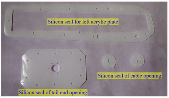
Figure 19.
Silicone rubbers for waterproof.

Figure 20.
Silicone rubbers for waterproof of cable opening.
The opening used in the cables used a clamp-type design. These cables passed through the silicon film with the opening in the center by using the upper two and lower one piece of acrylic clamp board to fix the silicon film. Among these, the upper silicon film is symmetrically cut in the center. The design uses six sets of screws and nuts to lock this acrylic and silicon set to this main patch board for the opening on the main hull.
2.8. Control Concept
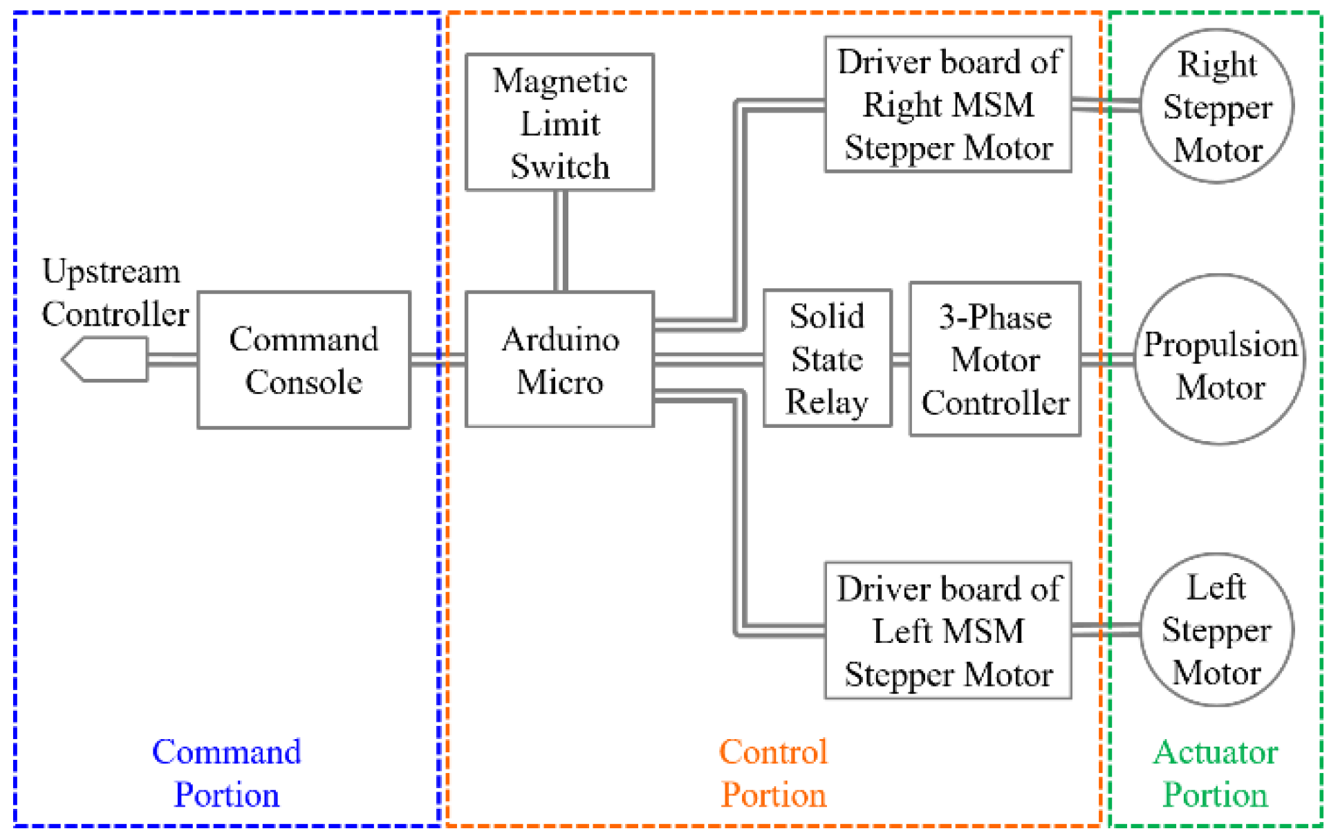
In this study, the feasibility of using this MSM as a motion control tool was verified. There were three portions of the control circuit, including instruction and monitoring, controller and sensors, and actuators, as in Figure 21. The main controller was programmable and followed the instructions of the program code. Instruction and monitoring were used to instruct the underwater vehicle in this study. Here, a personal computer worked as a control console. It was connected to an Arduino Micro control board on the underwater vehicle in this study via a USB cable. The Arduino Micro controller board was the major part of the controller and Sensors portion. Its I/O interface was connected to the limit switch for positioning and 9-axis IMU. Considering the perturbation in the water, the IMU was selected as the product with Kalman filter function. The actuator portion sought to execute the on and off actions of the controller. This portion included driver boards and motors.
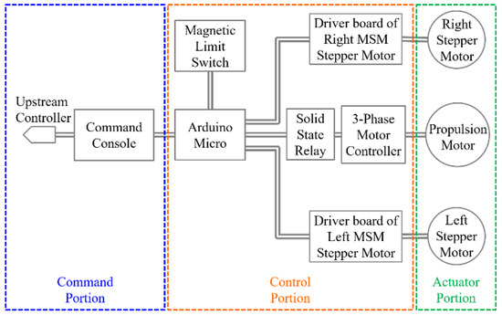
Figure 21.
Architecture of control concept.
2.9. Electronic Circuit
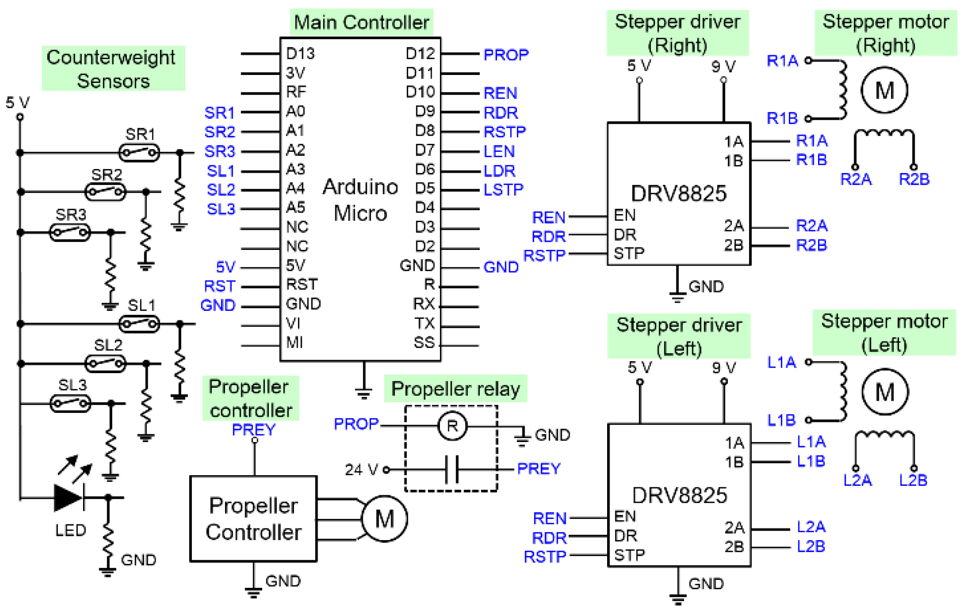
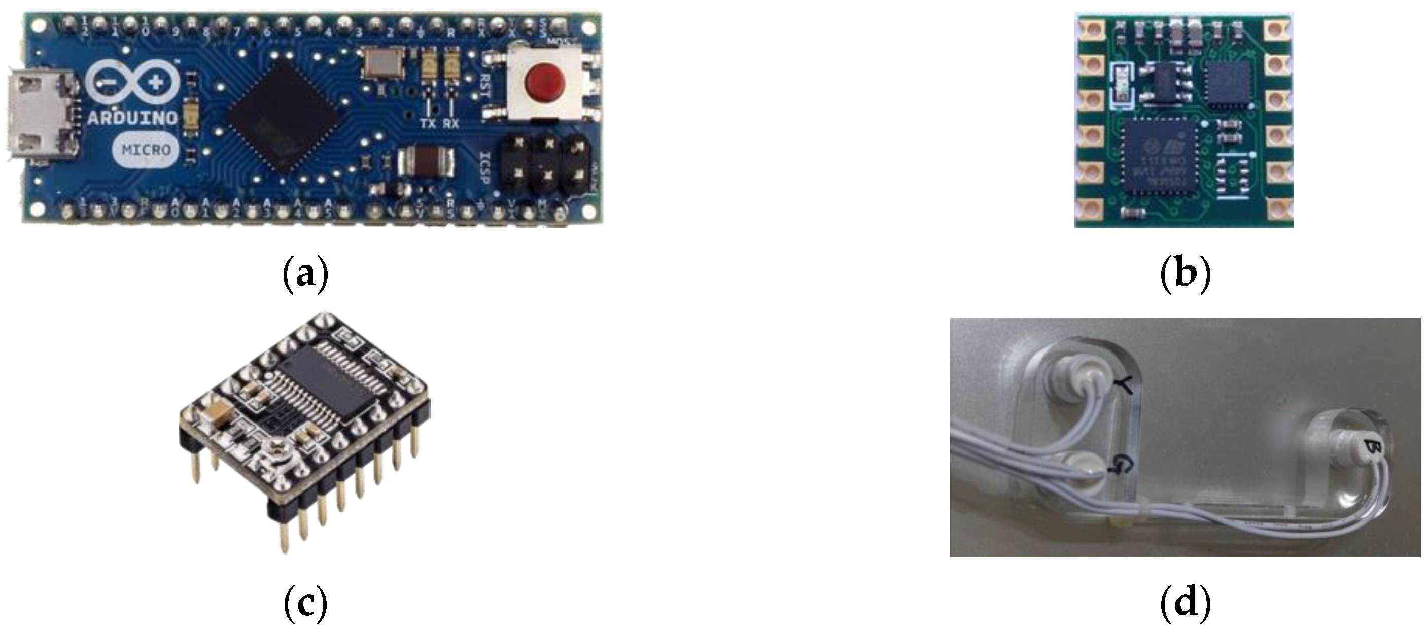
The electronic circuit was divided into several parts, including the main controller, sensors, propulsion control, and stepper motor driver, as shown in Figure 22. In addition, there were also boost converter and buck converter circuits required for power sources from batteries. The device modules were used to reduce the volume. Considering maintenance, each function portion was separated. The plugs and receptacles connected to each other. These circuits were combined with several components. The major components are shown in Figure 23.
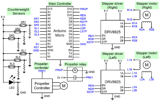
Figure 22.
Schematic of the Arduino Micro board and peripherals.

Figure 23.
Major components of circuit as: (a) Arduino Micro board; (b) 9-axis IMU; (c) Stepper motor driving module; (d) Magnetic limit switch sensor.
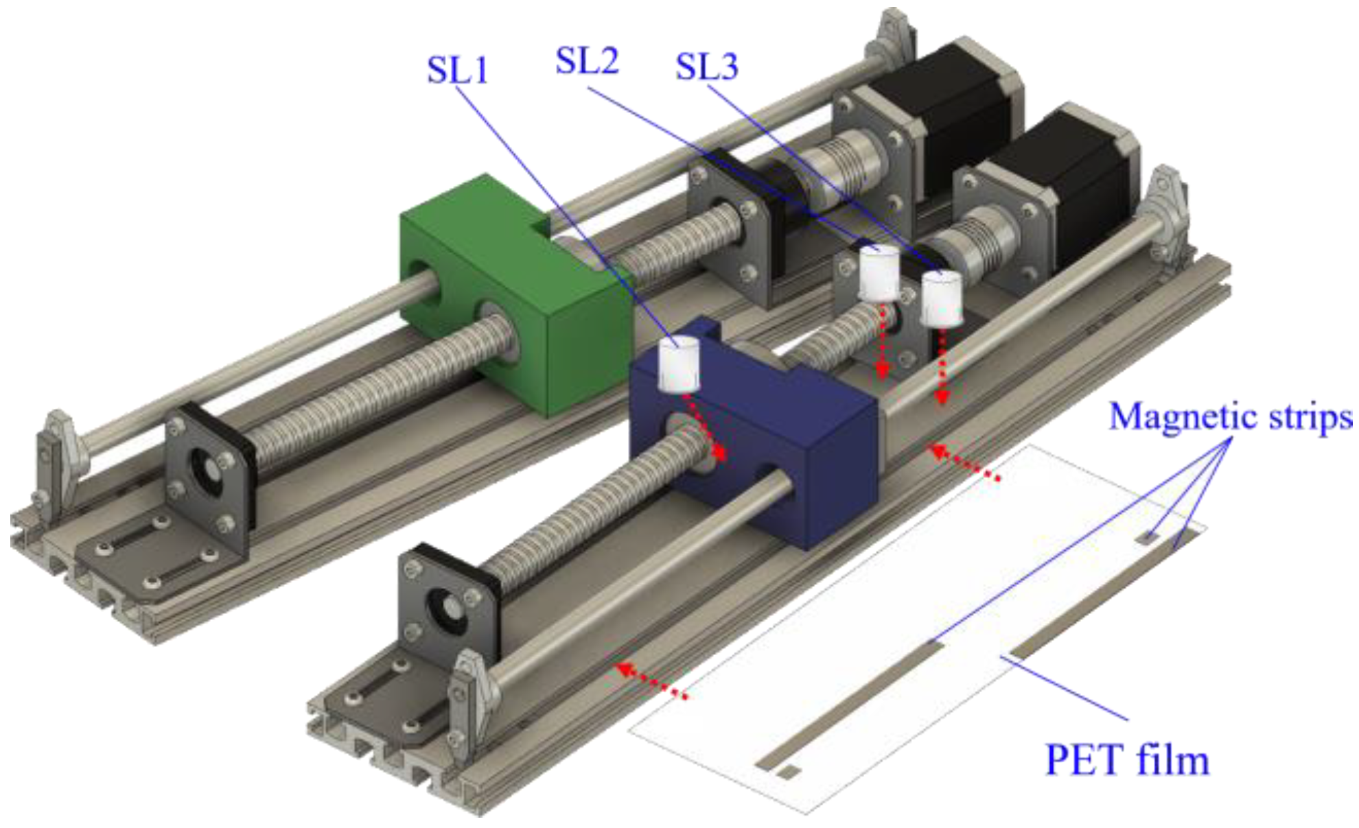
In order to move the counterweights to the proper positions, the sensors were equipped to detect the position of the counterweights. In this design, the counterweights moved to a fixed position to transfer of the center of gravity. Therefore, the magnetic limit switches and the magnetic strip were used as the position indicators, as shown in Figure 24. Three magnetic limit switches were used, marked as SR1/SR2/SR3 and SL1/SL2/SL3, indicating the three magnetic limit switches on the right and left sides of MSM, respectively. SL1 and SR1 were used to detect the front end and back end. SL2/SL3 and SR2/SR3 were used to detect whether the counterweights were in the forward stroke or the rear stroke. The excepted signals are shown in Table 2.

Figure 24.
Magnetic limit switches of position indicators.
Table 2.
Signal level of sensors.
We connected all of the magnetic limit switches to the voltage signal source. When the magnetic limit switches moved with the counterweight, the signals to the controller changed due to the corresponding positions of the magnetic strips, as in Figure 24. These signals are connected to the I/O interface of the controller and the controller sensed the counterweight positions. The controller turn the stepper motors used to drive the counterweight ball screws on and off to locate the counterweights at the correct positions. In this study, the alternative method was also used for positioning, to avoid interference in the IMU from the surrounding magnets. One magnet was fixed at the back-end as the zero point for SL1, and another magnet was used for SR1. The MSM performed the return-to-zero action at the beginning of the process. The stepping motors were driven to move the counterweights to the planned position based on 200 steps per revolution and the 5 mm of lead of the ball screw.
2.10. Power Sources
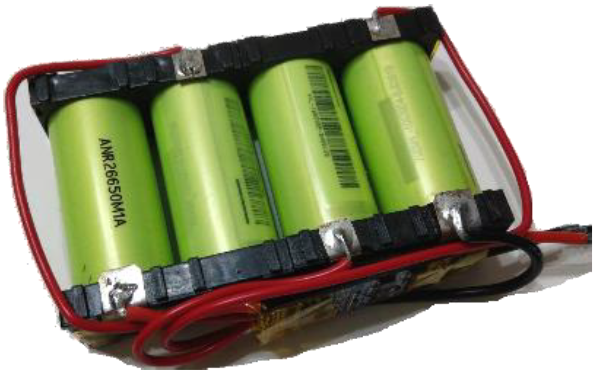
The target of this design was to act as a vehicle for long-term use underwater, and chargeable batteries were used as the power source. The thruster and stepper motor had large current consumption requirements, and so lithium-iron phosphate battery cells were selected as the entities of batteries. The formula of lithium iron phosphate is LiFePO4, abbreviated as LFP. It is a kind of lithium-ion battery, as in Figure 25. The lithium-iron phosphate battery is named after its positive electrode material. It is characterized by no precious elements, such as cobalt. The raw material price is low, as phosphorus and iron are abundant resources in the Earth. There are no supply problems. It has a working voltage of 3.3 V with high discharge power, fast charging, a long lifecycle, and high stability in high-temperature environments. In this design, two sets of four lithium-iron phosphate batteries were used in parallel. The first set was connected to the major system power and the second was the power supply for the propeller controller

Figure 25.
Lithium-iron phosphate battery assembly.
The boost converter is a kind of DC–DC power converter, which can increase the input power to the output voltage, but at the same time, it also reduces the current. It is a type of switch mode power supply (SMPS), which usually consists of several diodes, transistors, or a combination of these components in an IC, and energy storage elements such as capacitors, inductors, or a combination of both. In order to reduce the voltage ripple, a filter made by combining a capacitor and an inductor is usually added to the output of this type of converter.
The rated working voltage of the LFP battery is 3.3 V per cell. A 4-cell pack battery is 13.2 V. The LM6009 IC module used in this design boosted the 13.2 V voltage to the 24 V required by the thruster motor controller. A buck converter is also a type of DC–DC power converter and SMPS, which lowers the voltage from input to output, while increasing the current. Several LM2596 IC modules were used in this design to buck the 13.2 V voltage to the 5 V, 9 V, and 12 V values required by these controller circuits and stepper motors, as in Figure 26.
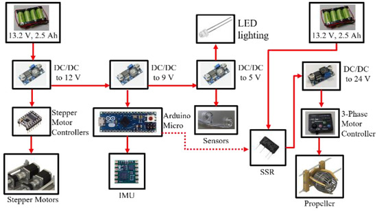
Figure 26.
Power distribution diagram.
2.11. Propeller Motor
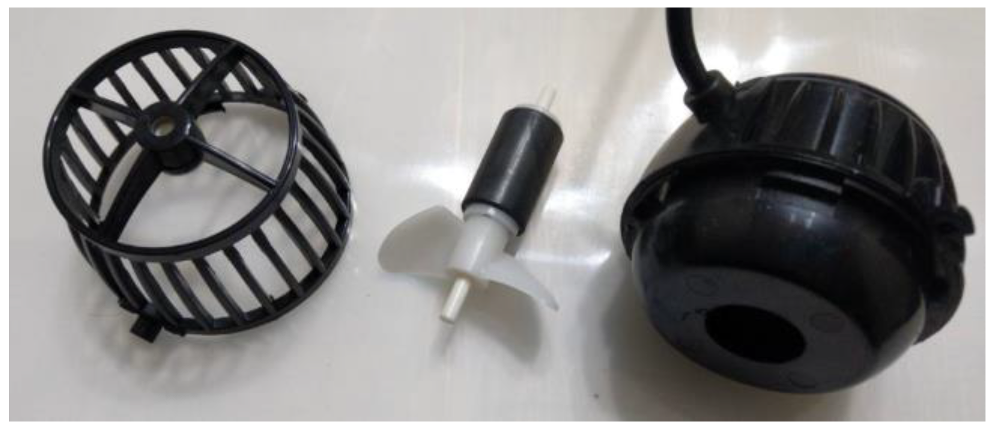
The brushless DC (BLDC) motor is a motor without brushes and commutators. Although it is a DC motor, there are no brushes and the operating principle becomes an AC synchronous motor. It uses an inverter to input DC power into the coils of the motor and control the direction of the BLDC motor. A BLDC mainly includes a permanent magnet and at least two sets of stator coils. The coils turn on and turn off. The permanent magnet is the rotor and the coil array is the stator. When the two poles of the magnet of the rotor are aligned with a certain set of coils, the set of coils loses magnetism when the power is cut off, and the next set of coils is started. Compared with the traditional brush type DC motor, the BLDC motor is more reliable. Because of the brushless contact with the rotor, BLDC motors are very suitable for use as underwater motors. In this study, an off-the-shelf wave maker of three-phase BLDC motor for aquariums, as in Figure 27, is used as the thrust source. The underwater motor can use water to cool the motor and propelle system.

Figure 27.
Underwater three-phase DC motor for AUV in this study.
2.12. Program for System Control
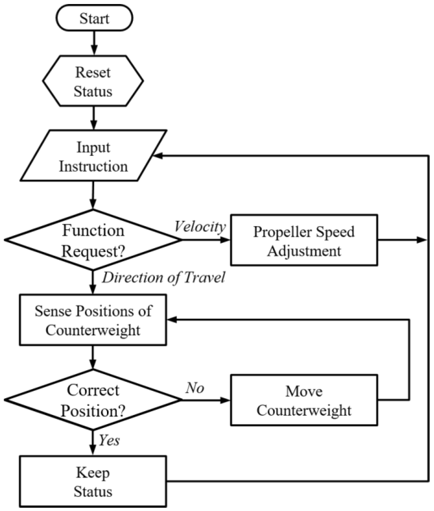
In this study, Arduino Micro single boards are used, as in Figure 23a. The program flow chart of this study is as in Figure 28. At the beginning of the control program, we reset all conditions of MSM and propulsion portions. Then, the system waited for the inputs of instruction to control the underwater vehicle in this study. Manual input was applied at the early stage. If the instruction was for velocity, the Arduino controller adjusted the revolution speed of the motor for the propeller. If the instruction is to change the direction, the controller senses the positions of counterweights. If the positions correctly match the setting, the controller do not send any signal to the drivers of the stepper motor. If not, it moves the position of the counterweights to the target positions set for such a direction.
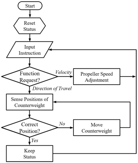
Figure 28.
Flow chart of control program.
2.13. Control Rules for Motions
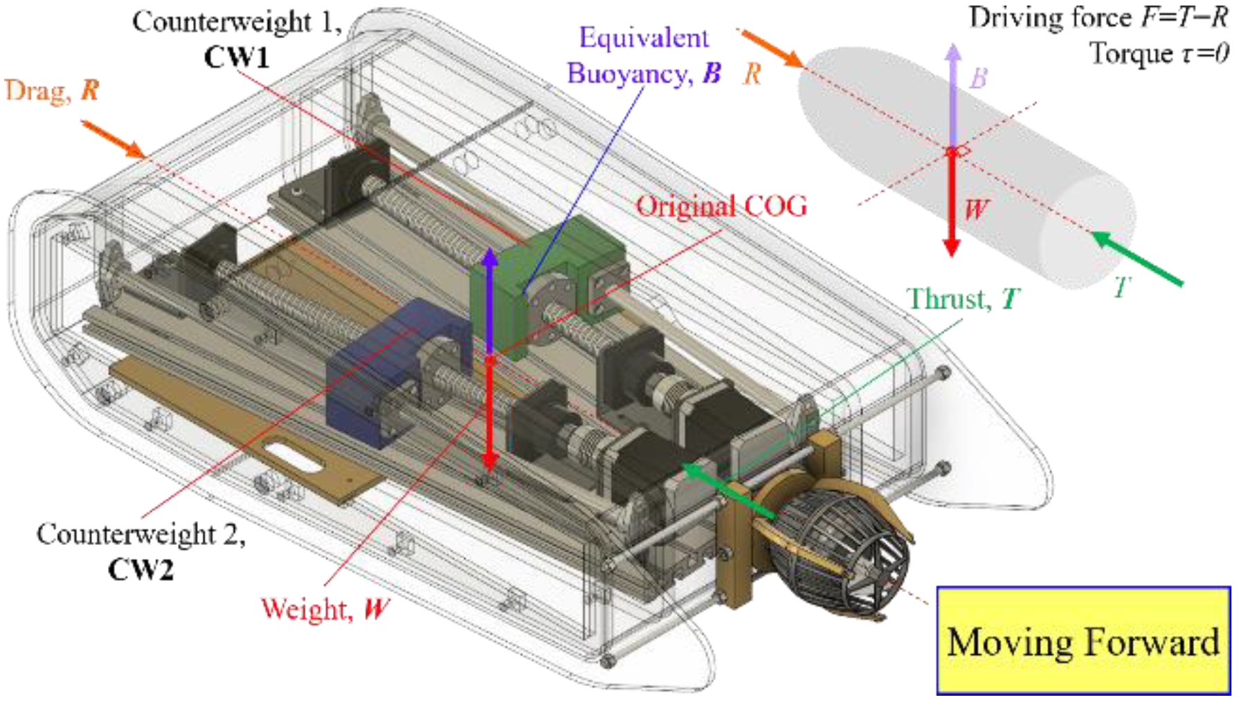
In this study, two movable masses were used as counterweights to perform the yawing, diving, and surfacing. The two movable masses’ positions for underwater control are as in Table 3. When the AUV move in a constant direction straight ahead, the two masses should remain in the original position where they are aligned with the line from the right mass to the left mass and the original center of gravity is inside this line. The right mass will move forward and the left mass will move backward to keep the X axis balanced but enlarge the distance d from the new COG to the original COG. The longer d will cause bigger torque to enlarge the right turning momentum of the underwater vehicle. The left turn also follows the same rule but in the opposite direction. The left mass will move forward and the right mass will move backward to keep the X axis balanced but enlarge the distance of d from the new COG to the original COG, and this torque will cause the system turn left.
Table 3.
Positions of two masses for underwater vehicle in this study control.
When the masses move back and forth in the operation of turning left or right, in addition to the torque in the direction of the Z axis or the -Z axis, the torque in the direction of the -X axis or the X axis is also be generated. The torque in the direction of -X axis and -X axis will cause the AUV body to roll. Therefore, the fins perpendicular to the X-Y plane have the effect of reducing the rolling of the body. According to the fluid dynamics, the fins perpendicular to the X-Y plane can reduce the rolling of the AUV. In this study, two fin-like acrylic panels cover the outermost ends of the hull to stabilize the system. Focusing on the design and control of MSM in AUV, the rolling of the AUV during yaw is considered minor and ignored in this research.
3. Results
3.1. Outlook of the New Underwater Vehicle
There are four major mechanical portions in the underwater vehicle in this study, including an outer hull, propulsion assembly, MSM, and brass chassis. The final assembly is shown in Figure 29 and Figure 30 A 10-m-long USB cable is used to connect to the underwater vehicle in this study. Through this cable, it can be connected to the Arduino to control the AUV and read the data of the IMU, and observe the images from the built-in camera. The current design configuration still requires connection to a personal computer on the shore to obtain IMU data. In addition, the camera will also use the software in the personal computer for recording images.
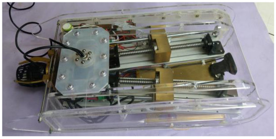
Figure 29.
Outlook of design.

Figure 30.
Design of key parts.
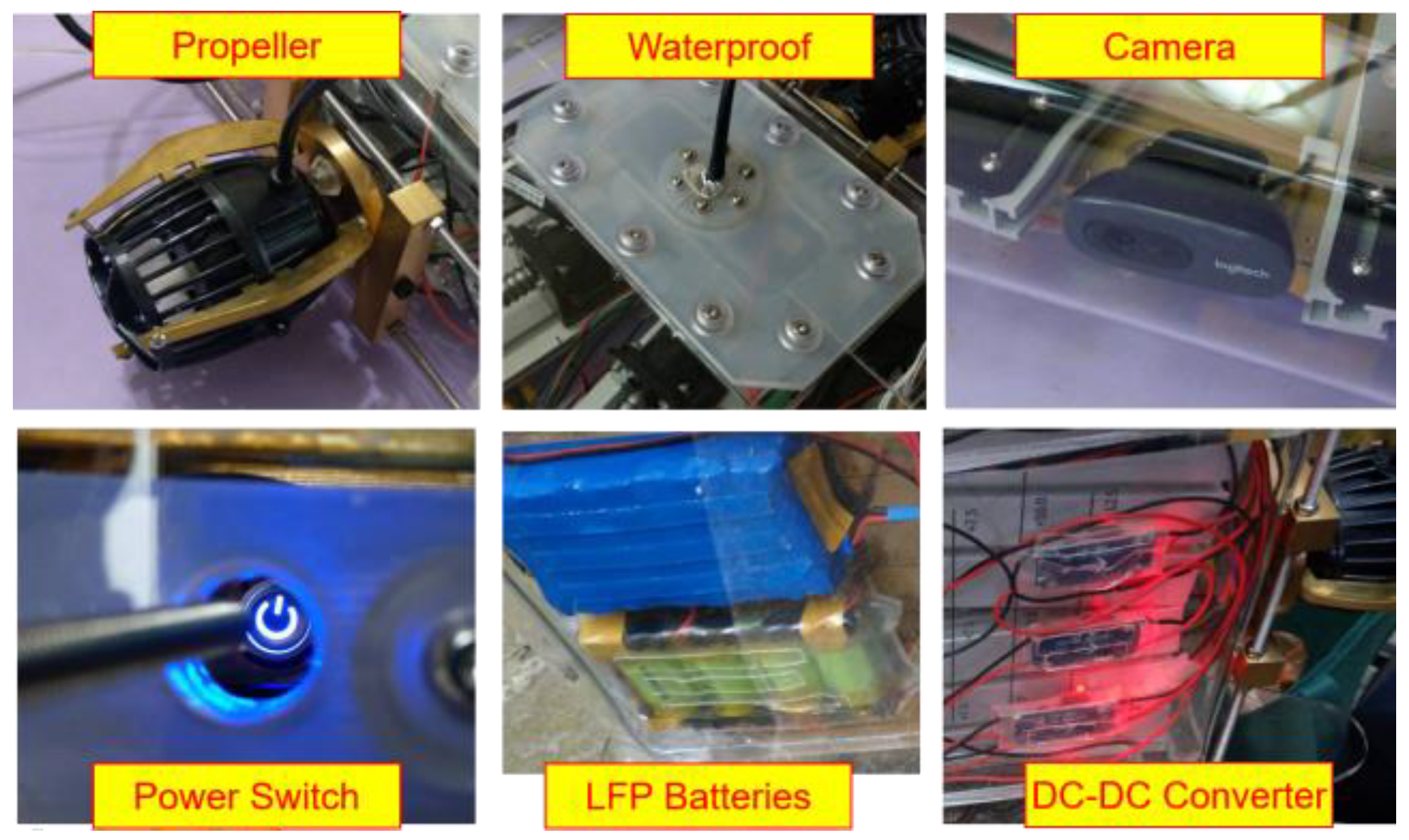
The detailed design of several main parts is as in Figure 30. As mentioned above, the waterproof pad mainly uses silicone as the acrylic partition, and then is attached to the case with stainless steel screws. The built-in camera is fixed on the front of the brass chassis. It is linked to the personal computer by a USB cable. The images from the camera are processed by the imaging software in the PC. The main switch of the system is located on the left-hand side of the body. It is locked with a hollow silicone plug and fixed with stainless steel screws. Using a long rod to reach in and press the switch, when the system is turned on and off, two sets of four parallel LFP batteries are used in this AUV as the main power source, and the batteries are fixed on the bottom shell of the AUV with double-sided tape. Three DC–DC buck convertors are glued to the AUV base, and when the power is turned on, the red indicator lights light up.
3.2. Verification
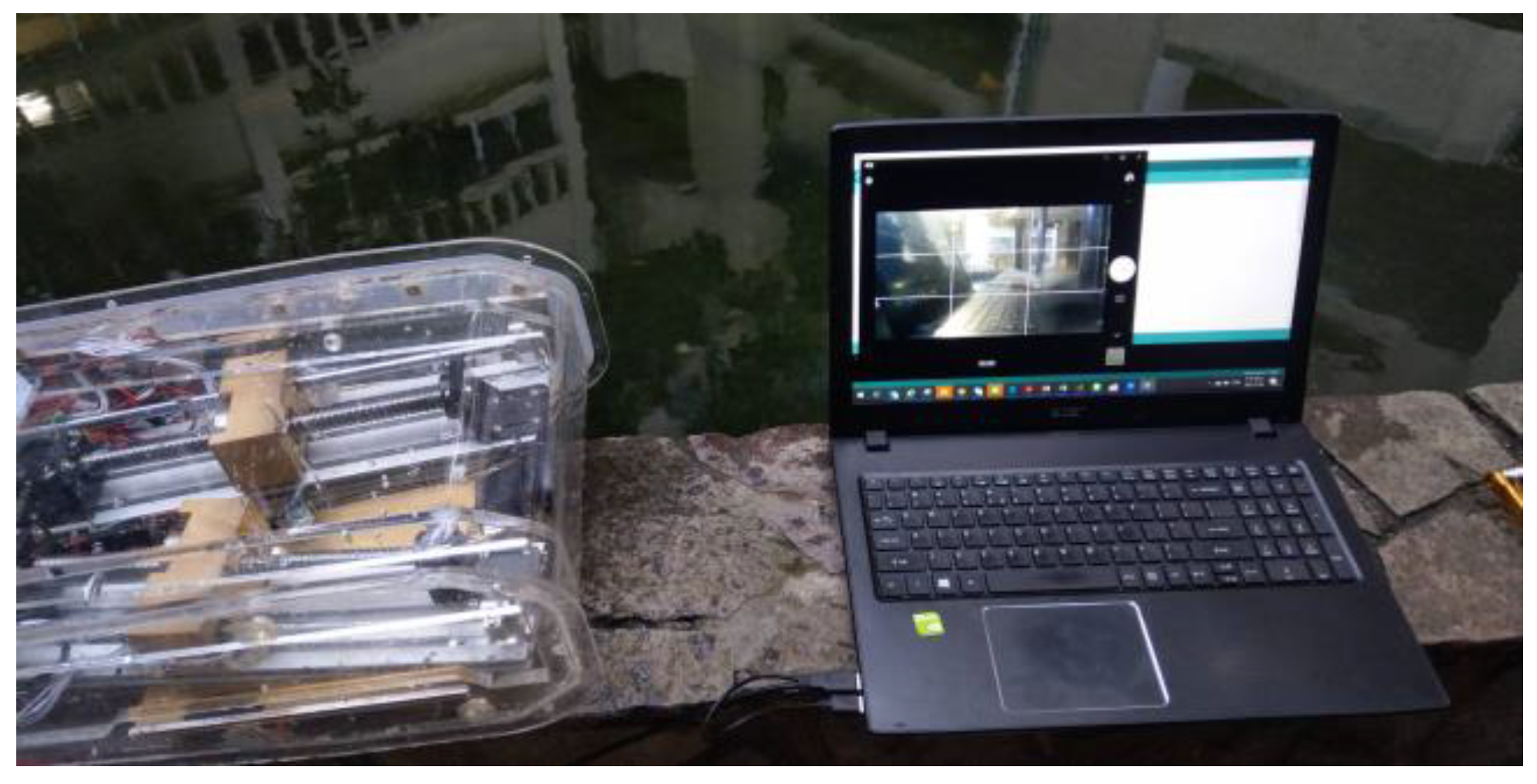
In this study, the AUV was tested to verify the designed functions. In this experiment, the test devices include the AUV, a personal computer, and a USB cable with a signal repeater, as in Figure 31. The test method is as below. The first step is to input a command into the personal computer. Regarding the command, there is a required status of the MSM or the three-phase motor. The Arduino board will check the status of the MSM and three-phase motor. If the status of the MSM and three-phase motor is not the same as the required status, the Arduino board controls the stepper motor control board to move the MSM to the required status. The results of the test show that for straight sailing, the functions of diving and ascent can be achieved, but the function of steering cannot be achieved.
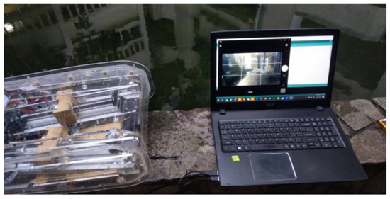
Figure 31.
Test devices.
3.3. Shift of Center of Gravity
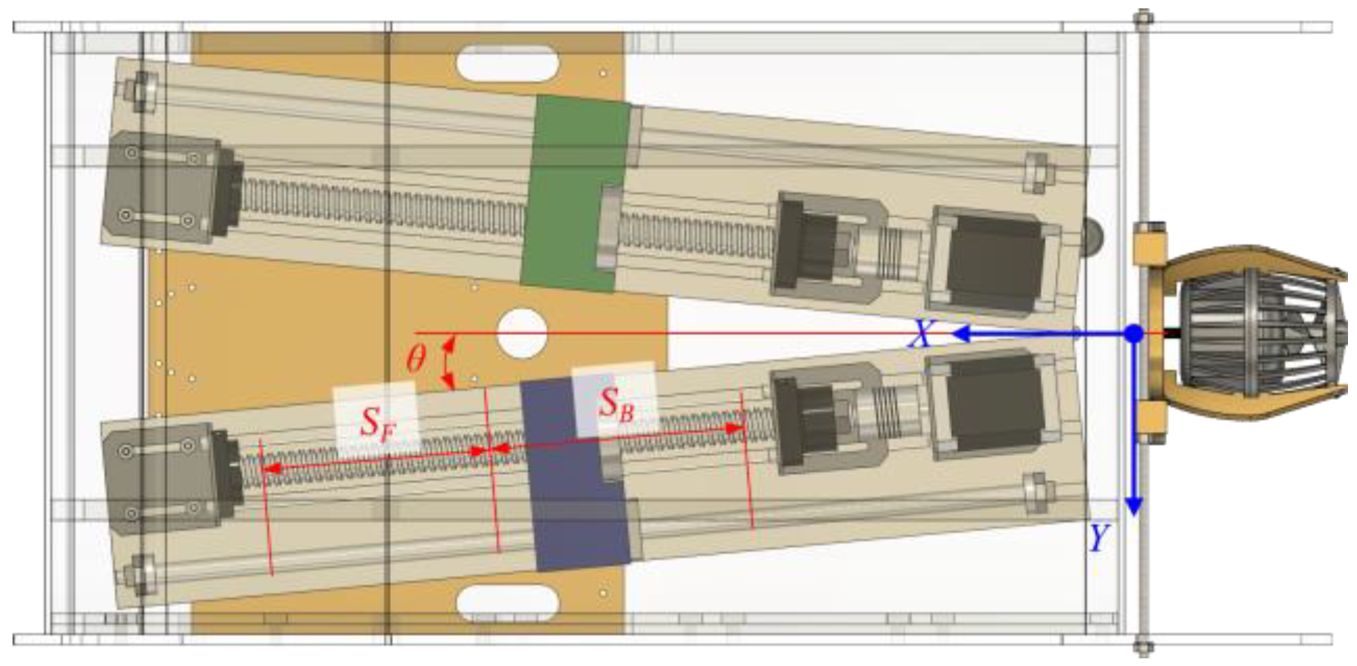
In a mechanical part, the center of gravity is the distance between each part and the reference point multiplied by the weight, and then divided by the total weight. In this design, for the moving counterweight, the shift in the center of gravity caused by the weight and relative distance of the object, according to the formula for the original COG, P0, is as in (7). The COG is changed to the new position, Pn. The new COG position, Pn, is related to the moving distance of the left and right counterweights. The equation is presented in (8) and (9). In this AUV, the angle of the MSM guide rails is θ for the right rail and -θ for the left rail to the center line, as in Figure 32. SF and SB are the stoke lengths of moving forward and backward for the two counterweights. The moving direction vectors of the two counterweights are for the right counterweight and for the left counterweight. They are calculated in (10) and (11). The weight of the left and right mass blocks is both m, and the Sa and Sb are the strokes of the right and left mass blocks’ movement. The torque that causes the AUV to steer is τ, as in (12), where dy is the displacement of the COG moving in the y direction, as in (13).

Figure 32.
Angle of the MSM guide rail in the AUV.
3.4. Thrust of Diving
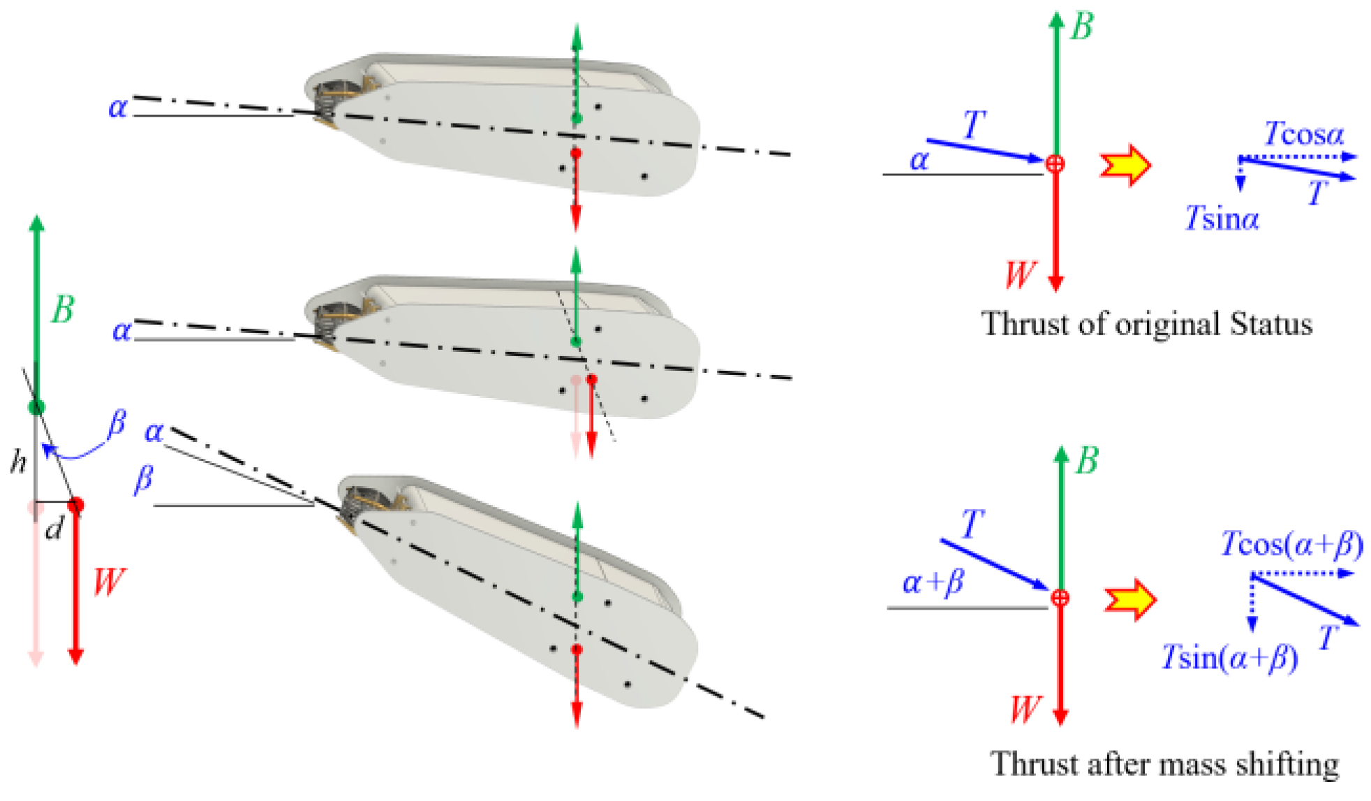
When the AUV is moving in a steady state forward, it will maintain an attach angle α corresponding to the horizontal plane. This angle will cause T to produce two component forces Ty0 and Tz0, according to the Y and Z axis, as in Figure 33. Tz0 is the net force of buoyancy B minus the weight W, as in (14). Additionally, Ty0 is the force to push the AUV to move forward, as in (15). After the mass shifting, the attach angle of AUV will increase β, as in (16), where h is the distance between the center of buoyancy and the original COG, and d is the distance the COG moves after mass shifting. The new component forces Ty1 and Tz1 after mass shifting are as in (17) and (18). The difference between Tz1 and Tz0 is the force needed to push the AUV to dive.
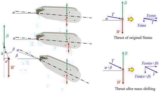
Figure 33.
Attach angle change after mass shifting for diving.
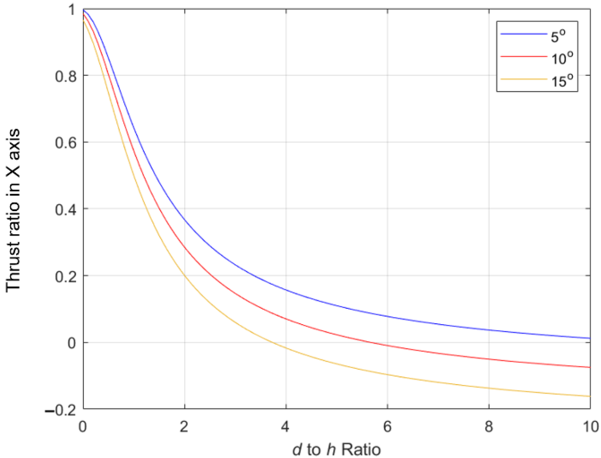
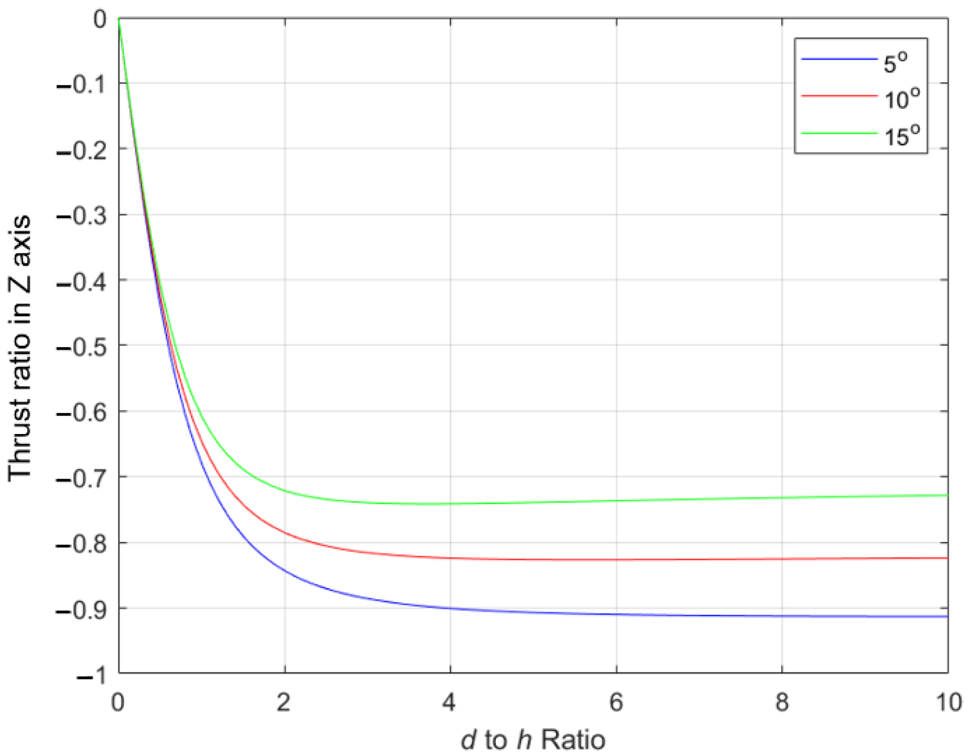
In this study, the distance the COG moves is a focus. According to (16), the attach angle after the mass moves is the arctangent function of d to h. When studying with the original alpha of 5°, 10° and 15°, it can be found that when the movement of COG is more than two times the value of h, the thrust acting on the AUV to dive in the direction of the Z axis gradually becomes insignificant, as in Figure 34. For the thrust in the forward direction, it will be reduced to 20–40% of the original thrust, as shown in Figure 35.
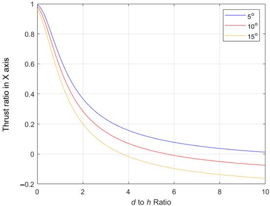
Figure 34.
Attach angle change after mass shifting for diving.
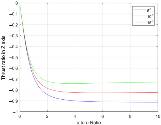
Figure 35.
The component force to move the AUV forward.
4. Conclusions
This paper presents the concept of a mass shifter mechanism for an underwater vehicle. It is one of the space-saving methods for AUV motion control with a simple mechanism instead of a conventional rudder and elevator. It is not necessary to design any linking mechanism connecting the moving parts outside. It can enhance the seal degree to cope with high water pressure in deep water. In this study, the design and manufacture of a prototype AUV are presented to verify the MSM method for AUV control. After testing, the surfacing and the diving functions are achieved. In addition, it is necessary to adjust the ratio of the mass of the counterweights to the entire system to generate sufficient torque to steer the autonomous underwater vehicle. Based on the results, the design of the ratio of the counterweight weight relative to the system weight and the movement trajectory are key design factors in this control method.
For future development, the optimization of the MSM design is an important topic. The quick movement of MSM to the required positions will help in operation and will reduce the fluctuation of the hull during the movement. The positioning method of the counterweights from the current discrete type to the continuity type can be suitable for adding an algorithm of control logic in complex control purposes. A continuous sensor or an encoder for a stepper motor feedback loop will help to position the counterweights accurately. In addition, a higher-precision IMU can also increase the control stability of the AUV. The current control method uses discontinuous positioning methods. Once continuous positioning such as encoders are used, more algorithms can be applied. In addition to the direction control, the stability of the AUV posture can also be considered for control. Stability, especially systems in the neutral position, is a topic for further study. Proper propeller selection can contribute to effective thrust and reduce energy loss. The CFD method is also planned in further research to obtain more accurate drag and thrust values for future enhanced designs.
In this study, only a camera is added to obtain images of the surrounding area. An IMU is used to sense the posture of the AUV. In future works, a water pressure gauge, depth gauge and sonar can be equipped on the underwater vehicle to enhance the functions of the data collection of AUV and algorithm or obstacle avoidance. In the experiment, the images from the embedded camera are not clear, because the underwater light is insufficient. Due to the reflection of light from the water surface, the captured images are too dark and make it difficult to recognize the content of the image. The visibility is also limited, at only within the vicinity of the AUV. Adding lights to the AUV will help the captured images to be clearer and increase the visibility distance, which will help in the collection of dynamic images or still picture data.
5. Patents
The patents resulting from the work reported in this manuscript are as follows: “Center of Gravity Adjusting Device for Aquatic Vehicle Motion Control”, Patent No. I673206, Country: Republic of China (Taiwan), October 2019.
Author Contributions
Conceptualization, M.-F.R.L.; methodology, M.-F.R.L. and Y.-C.C.; software, Y.-C.C.; validation, M.-F.R.L. and Y.-C.C.; formal analysis, M.-F.R.L.; investigation, M.-F.R.L.; resources, M.-F.R.L.; data curation, Y.-C.C.; writing—original draft preparation, Y.-C.C.; writing—review and editing, M.-F.R.L.; visualization, Y.-C.C.; supervision, M.-F.R.L.; project administration, M.-F.R.L.; funding acquisition, M.-F.R.L. All authors have read and agreed to the published version of the manuscript.
Funding
This research was funded by [Ministry of Science and Technology (MOST) in Taiwan] grant number [108-2221-E-011-142-] and [Center for Cyber-physical System innovation from the Featured Areas Research Center Program within the framework of the Higher Education Sprout Project by the Ministry of Education (MOE) in Taiwan].
Institutional Review Board Statement
Not applicable.
Informed Consent Statement
Not applicable.
Data Availability Statement
Not applicable.
Conflicts of Interest
The authors declare no conflict of interest.
References
- Schramm, K.D.; Marnane, M.J.; Elsdon, T.S. A comparison of stereo-BRUVs and stereo-ROV techniques for sampling shallow water fish communities on and off pipelines. Mar. Environ. Res. 2020, 162, 105198. [Google Scholar] [CrossRef] [PubMed]
- Love, M.S.; Nishimoto, M.M.; Clark, S.; Kui, L.; Aziz, A.; Palandro, D. A comparison of two remotely operated vehicle (ROV) survey methods used to estimate fish assemblages and densities around a California oil platform. PLoS ONE 2020, 15, e0242017. [Google Scholar] [CrossRef] [PubMed]
- Partridge, D.; Friedrich, T.; Powell, B.S. Reanalysis of the PacIOOS Hawaiian Island ocean forecast system, an implementation of the regional ocean modeling system v3.6. Geosci. Model Dev. 2019, 12, 195–213. [Google Scholar] [CrossRef] [Green Version]
- Karnauskas, K.B.; Jakoboski, J.; Johnston, T.S.; Owens, W.B.; Rudnick, D.L.; Todd, R.E. The Pacific Equatorial Undercurrent in Three Generations of Global Climate Models and Glider Observations. J. Geophys. Res. 2020, 125, e2020JC016609. [Google Scholar] [CrossRef]
- Kostakis, I.; Rottgers, R.; Orkney, A. Development of a bio-optical model for the Barents Sea to quantitatively link glider and satellite observations. Philos. Trans. R. Soc. A Math. Phys. Eng. Sci. 2020, 378, 20190367. [Google Scholar] [CrossRef]
- Billings, A.; Kaiser, C.; Young, C.M.; Hiebert, L.S.; Cole, E.; Wagner, K.S.; Dover, L.V. SyPRID sampler: A large-volume, high-resolution, autonomous, deep-ocean precision plankton sampling system. Deep Sea Res. Part II Top. Stud. Oceanogr. 2017, 137, 297–306. [Google Scholar] [CrossRef] [Green Version]
- Messié, M.; Shulmanc, I.; Martinid, S.; Haddocka, S. Using fluorescence and bioluminescence sensors to characterize auto- and heterotrophic plankton communities. Prog. Oceanogr. 2019, 171, 76–92. [Google Scholar] [CrossRef]
- Dodson, T.; Grothues, T.M.; Eiler, J.H.; Dobarro, J.A.; Shome, R. Acoustic-telemetry payload control of an autonomous underwater vehicle for mapping tagged fish. Limnol. Oceanogr. Methods 2018, 12, 760–772. [Google Scholar] [CrossRef]
- Tian, W.; Song, B.; Ding, H. Numerical research on the influence of surface waves on the hydrodynamic performance of an AUV. Ocean. Eng. 2019, 183, 40–56. [Google Scholar] [CrossRef]
- Li, Z.; Tao, J.; Sun, H.; Luo, Y.; Ding, L.; Deng, Z. Hydrodynamic calculation and analysis of a complex-shaped underwater robot based on computational fluid dynamics and prototype test. Adv. Mech. Eng. 2017, 9, 1687814017734500. [Google Scholar] [CrossRef] [Green Version]
- Zhu, Y.S.; Yang, C.J.; Wu, S.J.; Li, Q.; Xu, X.L. A space-saving steering method for underwater gliders in lake monitoring. Front. Inf. Technol. Electron. Eng. 2017, 16, 485–497. [Google Scholar] [CrossRef]
- McBride, M.W.; Archibald, F.S. Propulsion of Underwater Vehicles Using Differential and Vectored Thrust. U.S. Patent US6 581 537 B2, 23 June 2002. [Google Scholar]
- Geng, L.B.; Hu, Z.G.; Lin, Y. Hydrodynamic characteristic of synthetic jet steered underwater vehicle. Appl. Ocean. Res. 2017, 70, 1–13. [Google Scholar] [CrossRef]
- McBride, M.W.; Archibald, F.S. Buoyancy Control Systems and Methods. U.S. Patent US 7 921 795B2, 12 April 2011. [Google Scholar]
- Loc, B.M.; Choi, H.S.; Seo, J.M.; Beak, S.H.; Kim, T.Y. Development and Control of a New AUV platform. Int. J. Control Autom. Syst. 2014, 12, 886–894. [Google Scholar] [CrossRef]
- Tran, N.H.; Choi, H.S.; Bae, J.H.; Oh, J.Y.; Cho, J.R. Design, control, and implementation of a new AUV platform with a mass shifter mechanism. Int. J. Precis. Eng. Manuf. 2015, 16, 1599–1608. [Google Scholar] [CrossRef]
- Paley, D.A.; Zhang, F.; Leonard, N.E. Cooperative control for ocean Sampling: The glider coordinated control system. IEEE Trans. Control. Syst. Technol. 2008, 16, 735–744. [Google Scholar] [CrossRef]
- Cai, W.; Zhang, M.; Zheng, Y.R. Task assignment and path planning for multiple autonomous underwater vehicles using 3D Dubins curves. Sensors 2017, 17, 1607. [Google Scholar] [CrossRef] [PubMed] [Green Version]
- Liu, X.; Zhang, M.; Rogers, E. Trajectory tracking control for autonomous underwater vehicles based on fuzzy re-planning of a local desired trajectory. IEEE Trans. Veh. Technol. 2019, 68, 11657–11667. [Google Scholar] [CrossRef]
- Yan, Z.P.; Gong, P.; Zhang, W.; Li, Z.; Teng, Y. Autonomous underwater vehicle vision guided docking experiments based on L-shaped light array. IEEE Access 2019, 7, 72567–72576. [Google Scholar] [CrossRef]
- Yan, Z.P.; Zhang, J.Z.; Yang, Z.W.; Tang, J.L. Two-dimensional optimal path planning for autonomous underwater vehicle using a whale optimization algorithm. Concurr. Comput. Pract. Exp. 2021, 33, e6140. [Google Scholar] [CrossRef]
- Sung, M.; Kim, J.; Cho, H.; Lee, M.; Yu, S.C. Underwater-sonar-image-based 3D point cloud reconstruction for high data utilization and object classification using a neural network. Electronics 2020, 9, 1763. [Google Scholar] [CrossRef]
- Kim, Y.; Ryou, J. A study of sonar image stabilization of unmanned surface vehicle based on motion sensor for inspection of underwater infrastructure. Remote Sens. 2020, 12, 3481. [Google Scholar] [CrossRef]
- Yu, H.P.; Li, Z.Y.; Li, D.L.; Shen, T.S. Bottom detection method of side-scan sonar image for AUV missions. Complexity 2020, 2020, 8890410. [Google Scholar] [CrossRef]
- Fan, S.; Liu, C.; Li, B.; Xu, Y.; Xu, W. AUV docking based on USBL navigation and vision guidance. J. Mar. Sci. Technol. 2019, 24, 673–685. [Google Scholar] [CrossRef]
- Bai, M.; Huang, Y.; Chen, B.; Yang, L.; Zhang, Y. A novel mixture distributions-based robust kalman filter for cooperative localization. IEEE Sens. J. 2020, 20, 14994–15006. [Google Scholar] [CrossRef]
- Karmozdi, A.; Hashemi, M.; Salarieh, H.; Alasty, A. INS-DVL navigation improvement using rotational motion dynamic model of AUV. IEEE Sens. J. 2020, 20, 14329–14336. [Google Scholar] [CrossRef]
- Ji, D.X.; Rehman, F.U.; Ajwad, S.A.; Shahani, K.; Sharma, S.; Sutton, R.; Li, S.; Ye, Z.Y.; Zhu, H.; Zhu, S.Q. Design and development of autonomous robotic fish for object detection and tracking. Int. J. Adv. Robot. Syst. 2020, 17, 1729881420925284. [Google Scholar] [CrossRef]
- Lin, M.W.; Yang, C.J. AUV docking method in a confined reservoir with good visibility. J. Intell. Robot. Syst. 2020, 100, 349–361. [Google Scholar] [CrossRef]
- Zhong, L.J.; Li, D.J.; Lin, M.W.; Lin, R.; Yang, C.J. A fast binocular localization method for AUV docking. Sensors 2019, 19, 1735. [Google Scholar] [CrossRef] [Green Version]
- Betancourt1, J.; Coral1, W.; Colorado1, J. An integrated ROV solution for underwater net-cage inspection in fish farms using computer vision. SN Appl. Sci. 2020, 2, 1946. [Google Scholar] [CrossRef]


Publisher’s Note: MDPI stays neutral with regard to jurisdictional claims in published maps and institutional affiliations. |
© 2022 by the authors. Licensee MDPI, Basel, Switzerland. This article is an open access article distributed under the terms and conditions of the Creative Commons Attribution (CC BY) license (https://creativecommons.org/licenses/by/4.0/).