3.1. Requirements for a New Mechanism
During the sewing process, forces act on the needle which affect the gripping part of the needle bar. A measuring aid was designed to determine these forces. It was a modified stitch plate, which was equipped with strain gauges. The measurement of the forces acting on the needle during sewing on the investigated sewing machine is described in detail in [
20]. This measurement determined the forces with which the needle should be held during the sewing process. The needle must be held with a minimum force of 25 N when piercing. The force must be at least 15 N during drawing through the sewn material. The needle must be flexible during transfer. The weight of the needle bar should not increase significantly so as not to negatively affect the required torque of the drive motor.
One of the solutions to simplify the mechanical system and at the same time eliminate the problematic impact of the control element into the stop is to use the magnetic force to attach the needle using an electromagnet [
21]. The general advantage of electromagnetic control is that it allows the power supply parameters to be changed independently, regardless of the other mechanisms of the sewing machine, because they are not connected by any mechanical coupling. Another advantage is that the electromagnets can be overloaded for a short time, which allows their more efficient use. A relatively small stroke, approximately 2 mm, is required to operate the existing needle gripping system. For such small strokes, the use of electromagnets is a suitable choice due to their attractive force characteristics [
22].
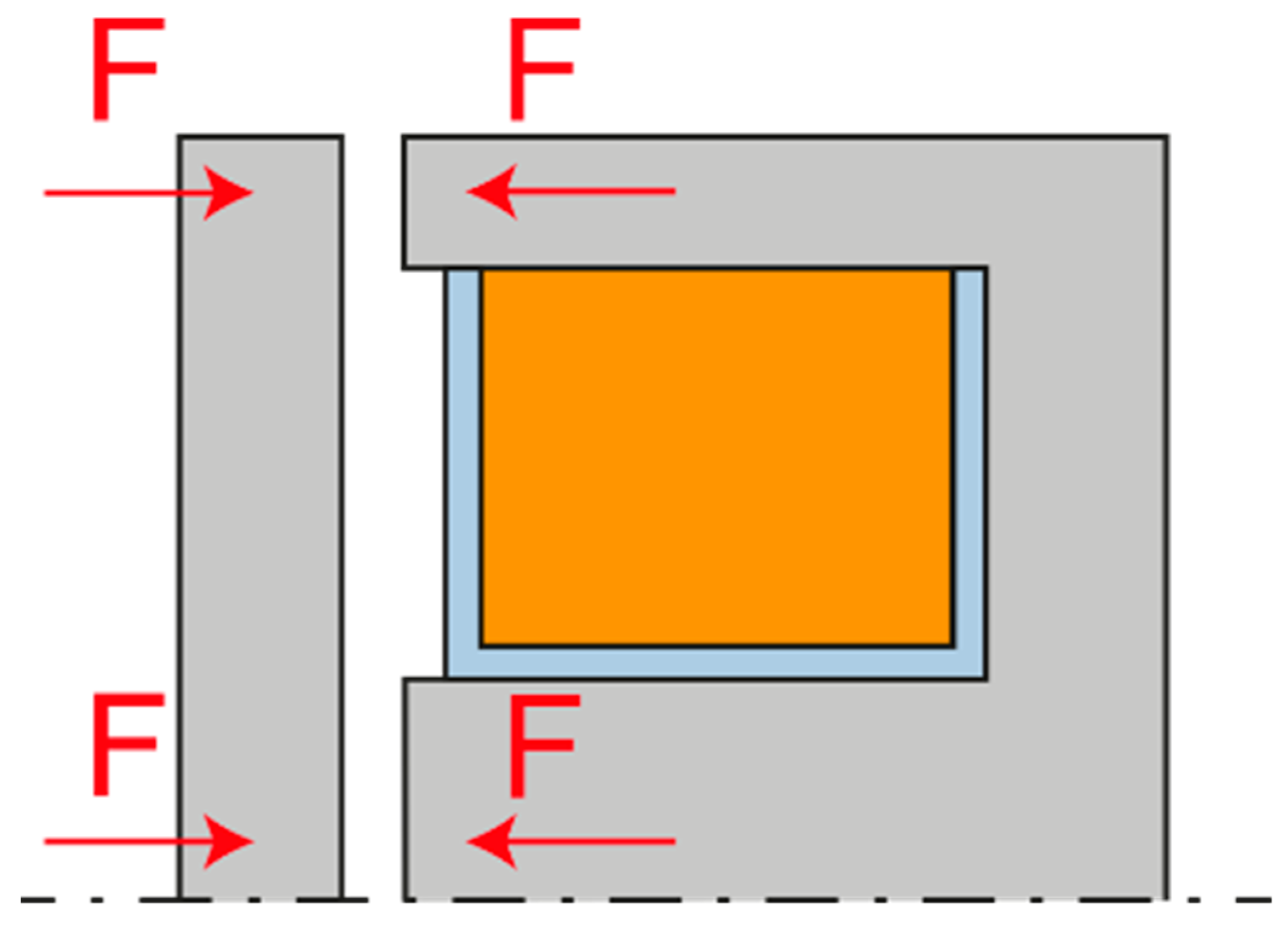
There are a number of arrangements, or constructions, of the electromagnet. The most basic electromagnetic arrangement is the front electromagnet, which is shown in
Figure 3. It excels in high strength in the attracted state. However, as the air gap increases, its strength decreases very sharply.
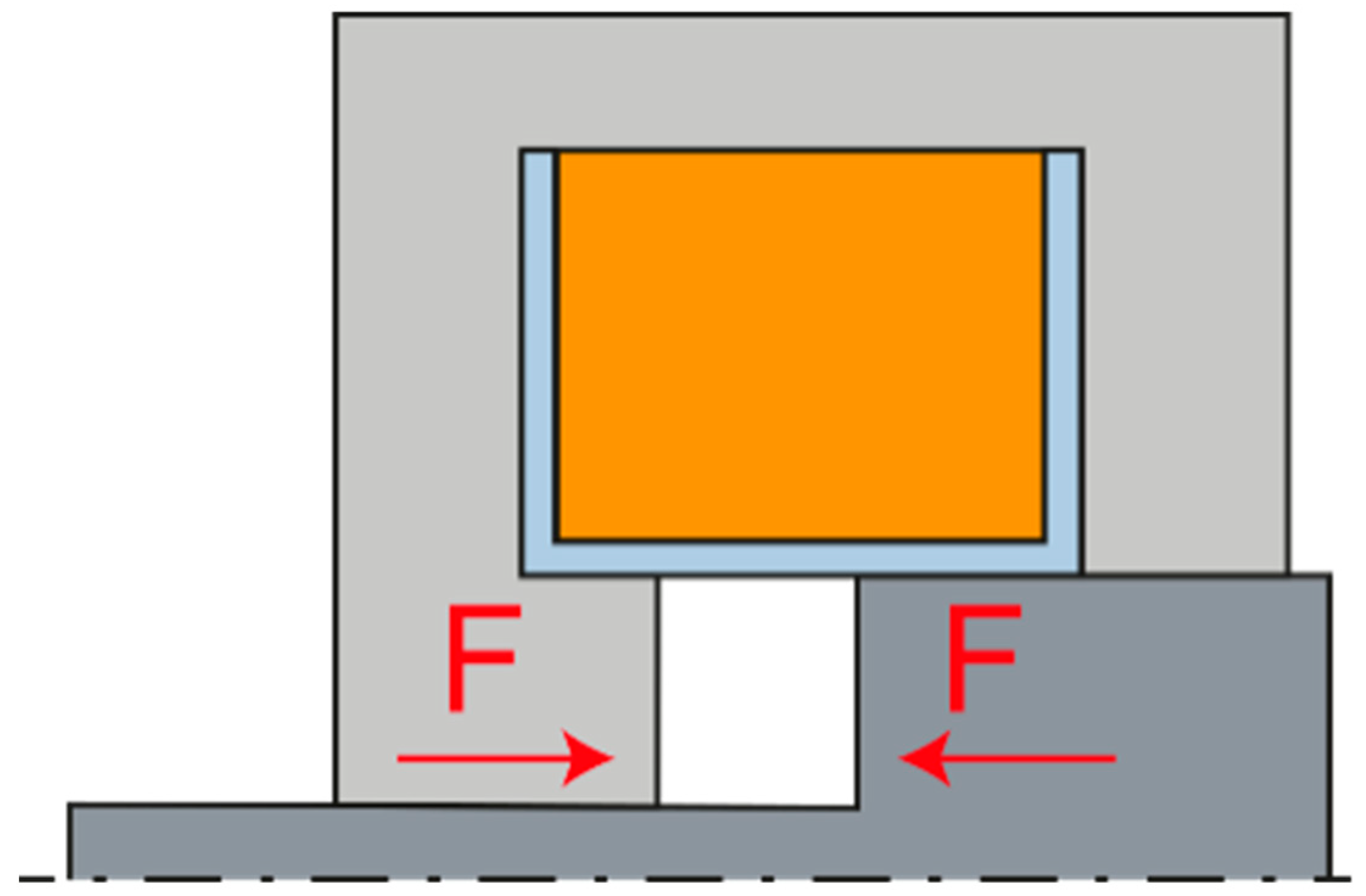
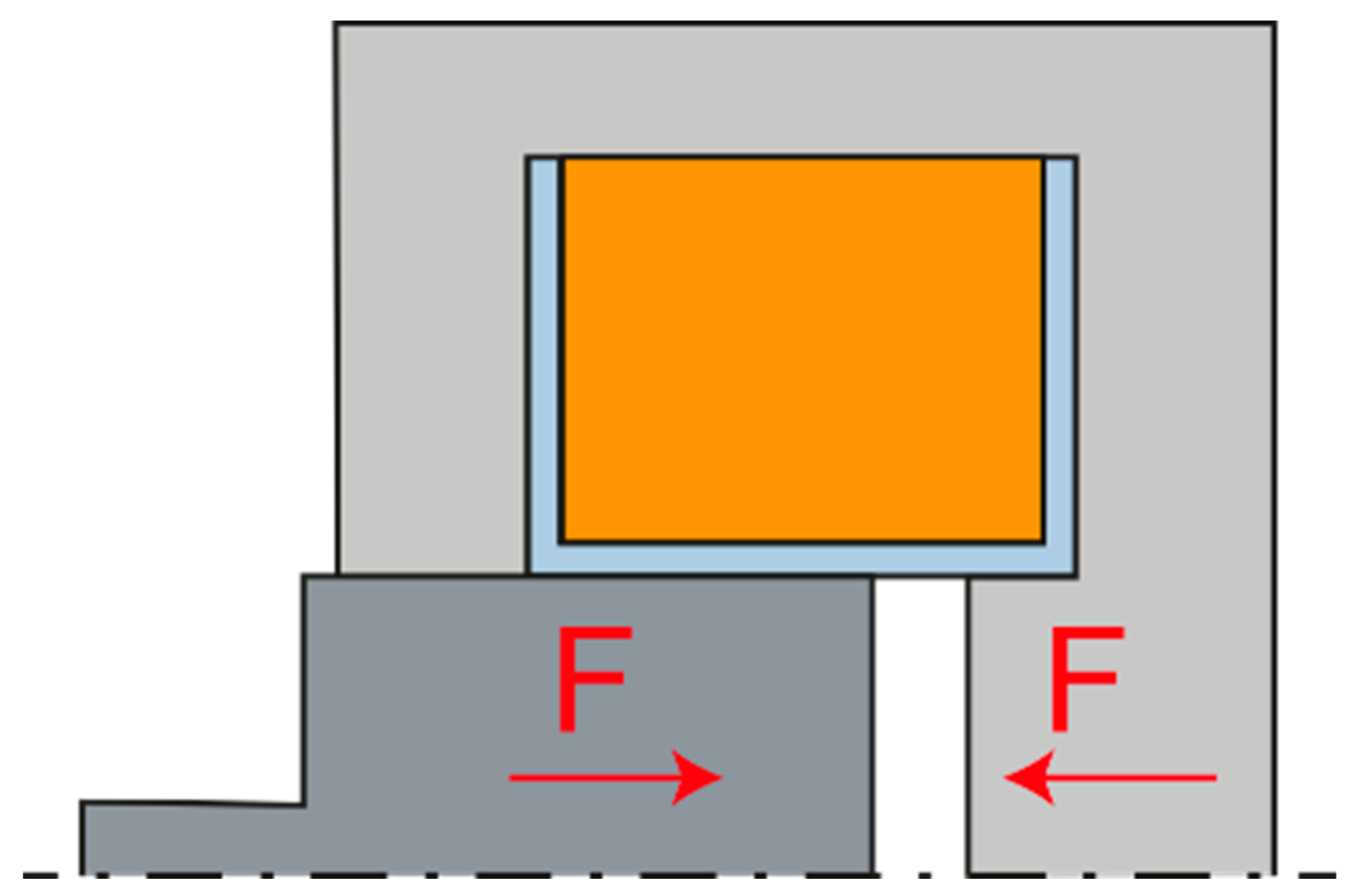
Another variant is the so-called solenoid, where the armature is pulled by an electromagnet. This solution is characterized by a more gradual decrease of the attractive force. It is therefore suitable for applications in which it is necessary to apply force at different anchor positions. The electromagnetic solenoid can exist in two variants, pushing and pulling, according to the direction of the derived arm force. The pushing arrangement shown in
Figure 4 has a flatter force characteristic, i.e., in the position of the zero air gap, it has a smaller attractive force, and on the contrary, in the position of the maximum air gap, it has a greater attractive force. The pulling arrangement is shown in
Figure 5.
In general, the magnetic force depends on the perpendicular cross-sections of the surfaces that make up the magnetic circuit, i.e., the larger diameter armature has a greater attractive force than the smaller diameter armature while maintaining the coil parameters.
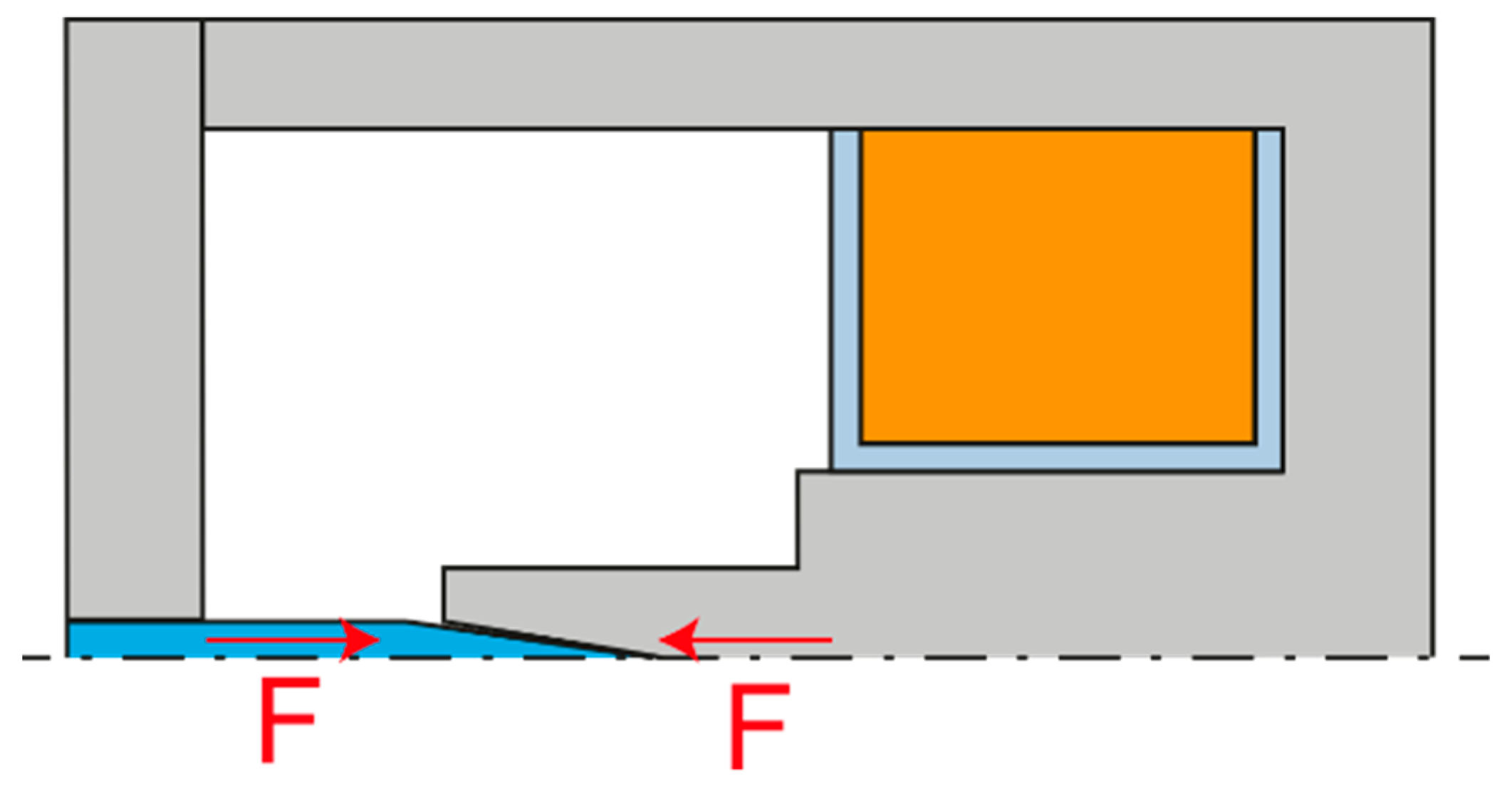
Another possibility is to use the needle itself as the armature of the electromagnet and, unlike the previous two variants, to omit the ball gripping mechanism, as shown in
Figure 6. However, due to the very small needle diameter, approximately 1 mm, the attractive force would be very small. This would not be a problem when piercing, but without a self-holding ball gripping mechanism, the needle could be easily pulled out of the gripper. This variant would therefore only be suitable for sewing delicate fabrics where there are no large frictional forces during drawing.
Two solenoid layout options allow us to design two variants of the mechanism. In the first, when the electromagnet is not energized, the spring closes the mechanism and keeps the needle gripped. In the second, when the electromagnet is not energized, the spring opens the mechanism. From the point of view of the functionality of the mechanism, it would be more appropriate to use the variant where the needle remains gripped and does not fall out spontaneously when the power supply is disconnected. However, it is necessary to perform a force analysis to select a more suitable variant for the dynamic characteristics of the needle bar.
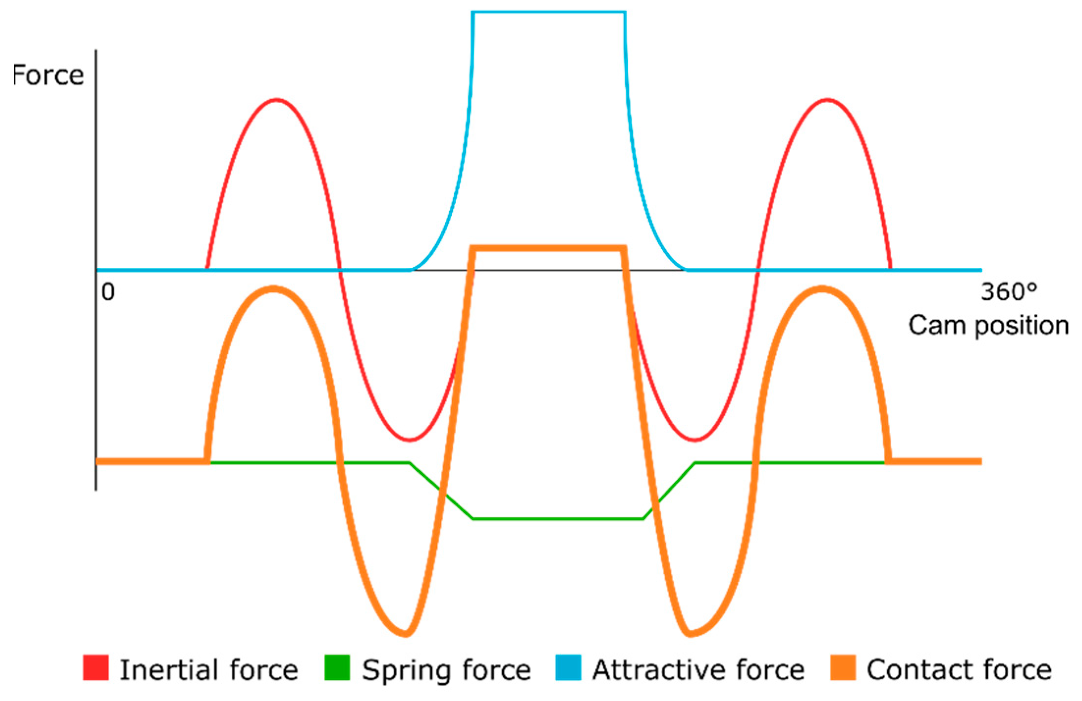
For an initial consideration of electromagnet design, we can specify which forces act on the control element. Inasmuch as we require the control element to move at the same speed and acceleration as the needle bar shell most of the time, we can define the required force that will act on the control element. Because the acceleration of the needle bar is precisely defined by the stroke dependence, we can determine the course of this inertial force relatively accurately.
Another force present is the force exerted by the spring, which returns the mechanism to its initial position. We assume that the spring has a linear stiffness characteristic. In the graph in
Figure 7, it should have a general force function in the transition area, but for simplicity it is shown as linear with respect to the rotation of the control cam [
23]. The last significant force is the attractive force of the solenoid. The force characteristic of the solenoid is hyperbolic depending on the actual size of the working air gap.
We can also show the contact force between the control element and the needle bar shell. If we want the control element to be in a clearly defined position, the contact force must be negative for the closed state and positive for the open state. Contact force can be zero with no contact. During needle release, this force determines the acceleration of the control element relative to the needle bar shell. This phenomenon is very important as it determines the time for which the needle will be released or attached. When analysing the force characteristic, the time at which the gripping mechanism is closed or opened is important. For the purpose of simplification, in this case, this time is chosen in the sinusoidal acceleration amplitude. If we plot all the forces in the graph in
Figure 8 as a function of the cam rotation, we can observe several important findings.
In the case of a solenoid in the pushing arrangement, its applied force in the attracted state must be greater than the sum of the force exerted by the spring and the amplitude of the inertial force so as not to disengage the control element from the needle bar shell. In other words, the total force acting on the control element must be less than zero in the interval when the required needle gripping and greater than zero in the interval when the needle is released.
If we compare the variant of the push and pull solenoid, we find that there are a number of differences. The fundamental difference is that the pull solenoid only exerts force when the mechanism is in the open state. This means that in order to compensate for the accelerating force when moving the needle bar, there is only a spring, which must therefore exert several times more force than in the case of the push solenoid. Assuming that the working stroke is the same for both springs, this spring would certainly have larger installation dimensions and greater weight. The second problem is that the pull solenoid has the least force at the largest air gap, that is, at the exact moment when we need to open the gripper quickly.
For the following reasons, the variant with the push solenoid was chosen for the solution. The acceleration of the needle bar only occurs when the needle is gripped, i.e., at the moment when the push solenoid exerts the greatest force. In addition, due to the shape of the armature, the push solenoid exerts more force than the pull solenoid at the moment of the largest air gap. Nevertheless, there is one disadvantage. When the power supply is disconnected, the needle is released by the return spring.
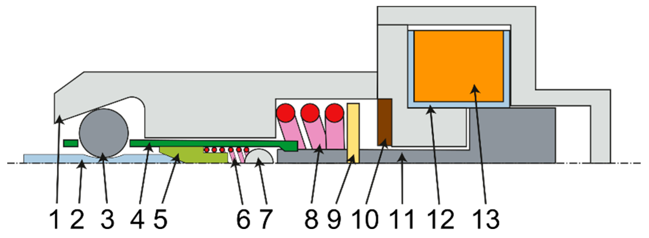
Figure 9 schematically shows the new needle bar design. The needle bar shell 1 must be made of several pieces in order to be able to assemble the mechanism. The needle 2 is held by balls 3 housed in a roller 4. The roller is controlled by a part 9, which is screwed onto the armature of the electromagnet 11. The armature is returned to its initial position by a spring 8. The electromagnet itself consists of a coil 13 and a frame 12. The movement of the armature is damped by a rubber pad 10. To seat the needle, there is a roller 5, which is returned by the spring 6 to the basic position. The spring is supported on a pin 7, which is fixed in the needle bar shell.
3.2. Winding Dimensioning
The design of the electromagnet winding is a relatively complex issue that solves the magnetic fluxes around the coil, the heat dissipation from the coil space to the surroundings also plays a big role here. The usual procedure in the design of electromagnets is the use of empirical relationships, which are based on simplifying assumptions, especially discretization of a continuous problem into several material blocks. Here, the methodology of Professor Cigánek is used [
24].
The calculation is based on the empirical equation of the attractive force
F of the electromagnet:
including the induction in the centre of the coil
B, the armature diameter
d, the magnetic flux deflection factor
ε and the flux increase factor
ν.
For an approximate calculation of the armature diameter, we can use this equation:
in which only the required attractive force
F occurs at the required air gap
δ.
For a more accurate calculation, it is then necessary to use this equation:
in which there are other auxiliary factors and selected parameters. Specifically, the ratio of winding thickness to armature diameter
β, length ratio
λ to armature diameter, coil winding factor
ξ (i.e., how much geometric space of the coil is occupied by the copper itself), conductor resistivity at operating temperature
ρ, magnetic circuit saturation factor
ks, heat conduction coefficient
α, and finally the temperature difference between the operating temperature and the environment
ϑm.
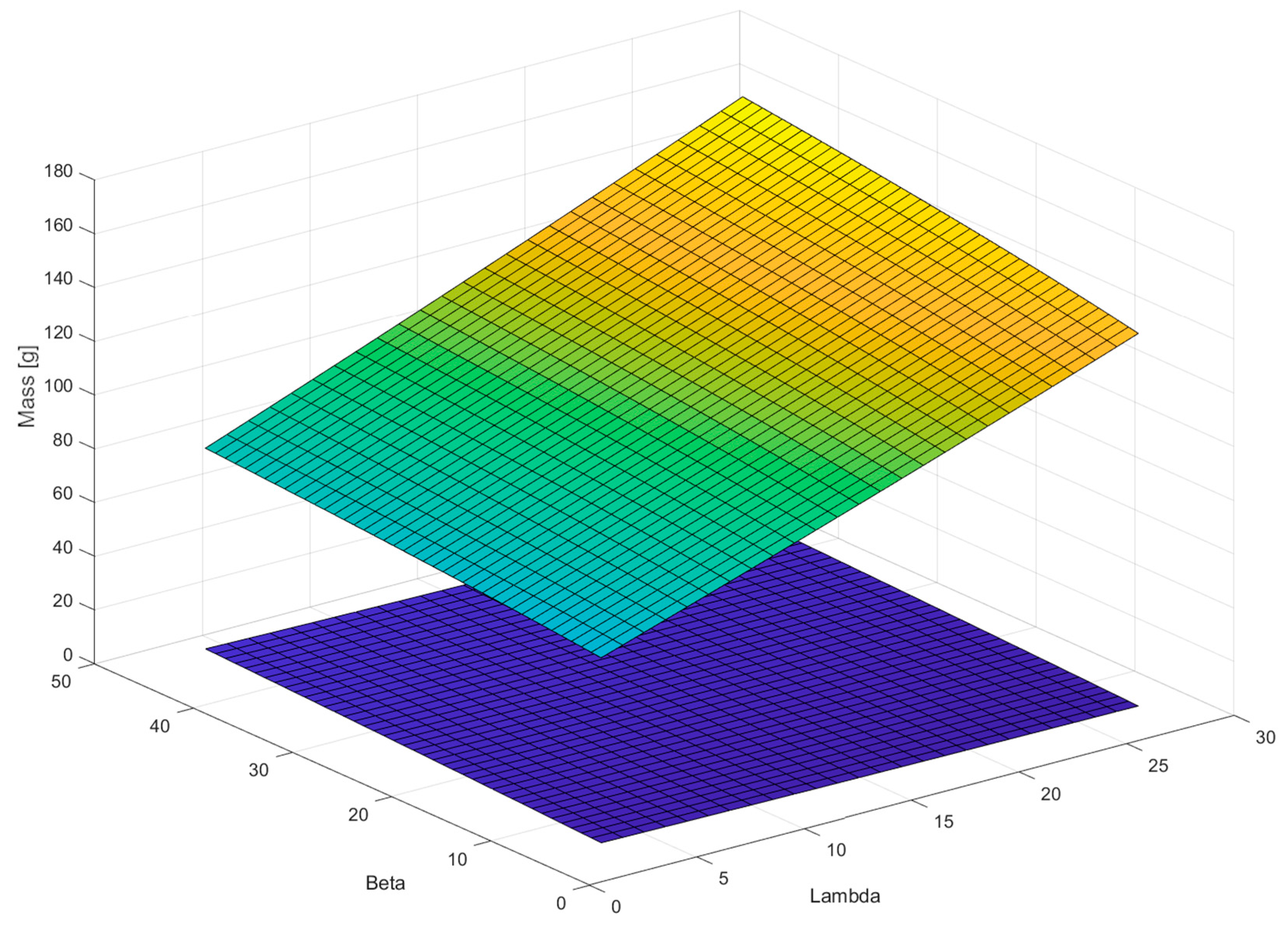
Figure 10 shows the course of the coil weight (green-yellow area) and the armature weight (purple area) depending on the parameters
β and
λ. It is possible to see the opposite trends of both dependencies, so it is necessary to select values that will compromise the requirements for the weight of the armature and coil.
The calculation of the factors
ν and
ε can be performed using the following relations, although these relations contain an average
d, which is currently unknown. It is either possible to use an approximate relation to calculate the mean
d, or to calculate these three equations iteratively until the deviation is acceptably small. In practice, the average
d is chosen as an integer for production reasons, so accuracy does not matter much at this stage.
This relation applies to the cross section of conductor
S:
The number of turns of coil
N is calculated as follows:
The approximate value of the induction in the centre of the coil
B can be expressed by the relation:
The last equation needed for the calculation is the steady state equation of the flowing current
I:
The result of these empirical equations are the calculated values of armature diameter d (respectively radius r1), coil length L and coil diameter D (respectively radius R), coil conductor diameter dC and current I flowing through the coil at a given voltage. Other values that need to be selected are related to the design of the electromagnet itself, especially the air gap between the components.
The calculation performed should be taken as a guide only, as it applies to the pull solenoid, not the push solenoid, which has a different design and different magnetic conditions. Nevertheless, it provides enough input information to create an electromagnetic simulation that calculates the attractive force much more accurately.
Table 1 shows the reference parameters.
Table 2 shows the main calculation parameters of the coil.
In
Figure 11, it is possible to see the proposed dimensions that are needed to create a simulation model of the attractive force; the values of the dimensions are entered in
Table 3. The table contains the construction dimensions of the electromagnet, which are based on the technological possibilities of electromagnet production and the construction arrangement of the needle bar. The basic parameters obtained on the basis of the calculation given in
Section 3.2 were respected during the design.
3.3. Simulation of the Attractive Force of an Electromagnet
As already mentioned, the empirical design serves only to approximate the dimensions and is, today, no longer sufficient due to its low accuracy. At present, it is possible to use numerical electromagnetic simulation based on the finite element method. There are several pieces of software that deal with this issue; the program FEMM 4.2 [
25,
26] was chosen for this work, because it has an integrated interface to the Matlab environment, which continues to work with data.
The computational model is static, i.e., the entire magnetic circuit is in a steady state. This is advantageous for simulating the end positions in which the electromagnet remains. In this case, however, we are also interested in the state between the end positions, which can be achieved by a quasi-static problem, i.e., by dividing into discrete time steps in which the circuit is static. This introduces a certain inaccuracy into the model, but this procedure is sufficient to determine the attractive force characteristic.
As a result of the electromagnetic simulation, we are particularly interested in the characteristics of the attractive force of the electromagnet, i.e., its dependence on the size of the air gap. The second important datum is the total inductance of the electromagnet, which is important for the design of the electrical circuit of the coil supply.
In the simulation, we discretize the whole problem into a so-called finite element network; the software can create this network itself based on the defined geometry and parameters, such as the maximum element size. The network element type is set to a triangle, the minimum angle of the triangle is set to 30°, and the required accuracy is set to 1 × 10⁻⁸.
The boundary condition is set to a free environment whose radius is 120 mm, as can be seen in
Figure 12.
Furthermore, it is necessary to define the materials of individual bodies because during magnetization, it is necessary to know the relative permeability and hysteresis B-H curve. The coil is defined by the resistivity of the conductor, the cross section, the number of turns and the current flowing.
The material of the core, hence the metal casing of the coil, must be chosen with regard to its magnetic properties. In general, relative permeability affects the magnetic flux, so the greater the relative permeability, the less resistance of the material to the passing magnetic flux. The shape of the hysteresis B-H curve affects the magnetic losses or the inductance of the entire electromagnet.
Magnetically soft steels are used as core materials, i.e., steels which, after the elimination of the magnetic field, do not remain magnetized, so that their attractive force is close to zero. These steels consist of either almost pure iron or, conversely, a very high alloy content. For comparison, two steels were selected that have all of their parameters defined in the FEMM 4.20 program, namely AISI 1010, which has an iron content of 99.5% and a steel called Supermalloy, which contains 5% iron, 79% nickel and 5% molybdenum.
The FEMM simulation program can be controlled using commands in the Matlab script, which allows us to iterate between the individual variants very quickly, as everything can be automated. The quasi-static state is achieved by gradually shifting the geometry of the anchor, i.e., by reducing the air gap. At each state, the attractive force is calculated, which is equal to the volume integral of the Lorenz force.
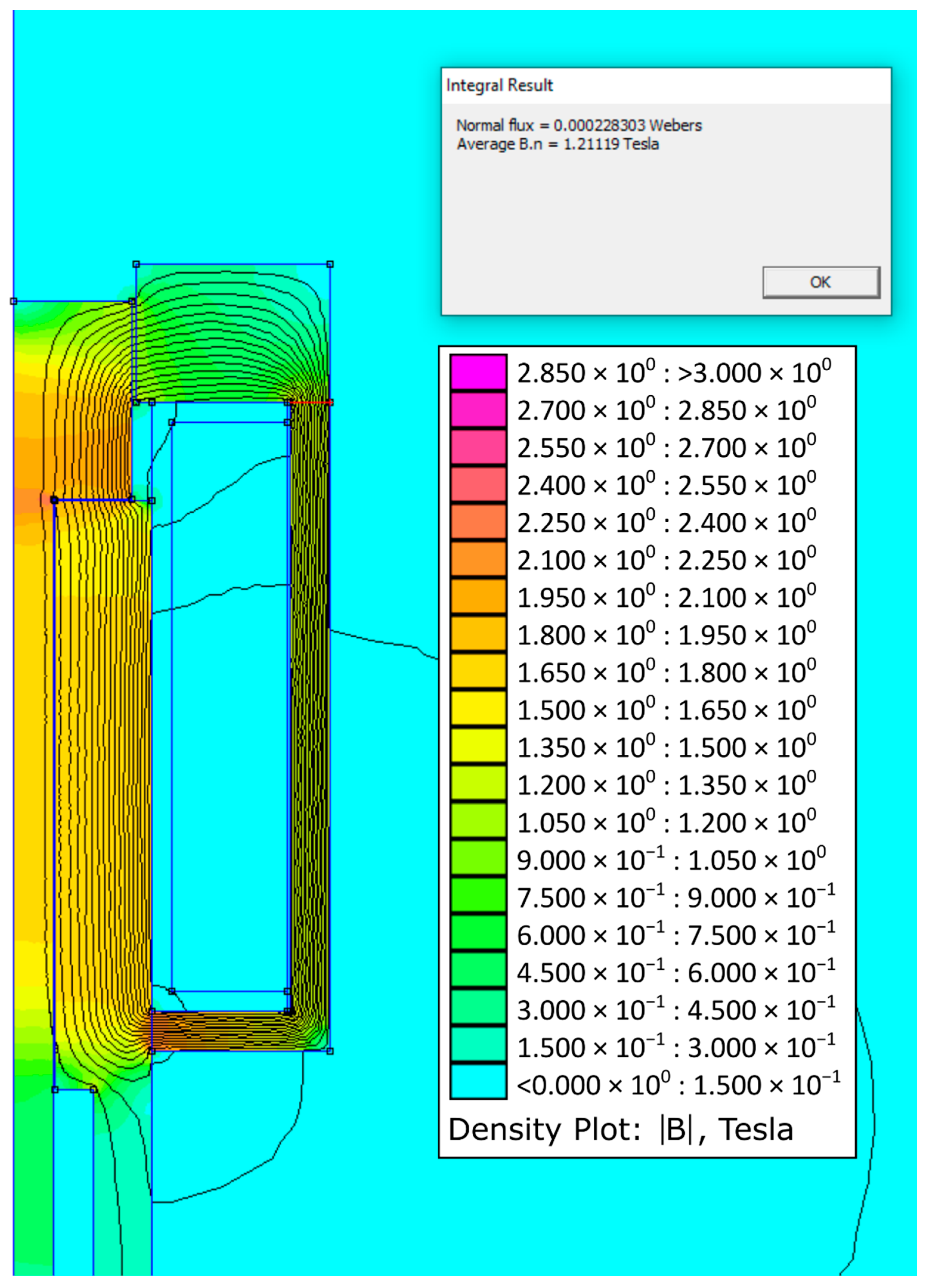
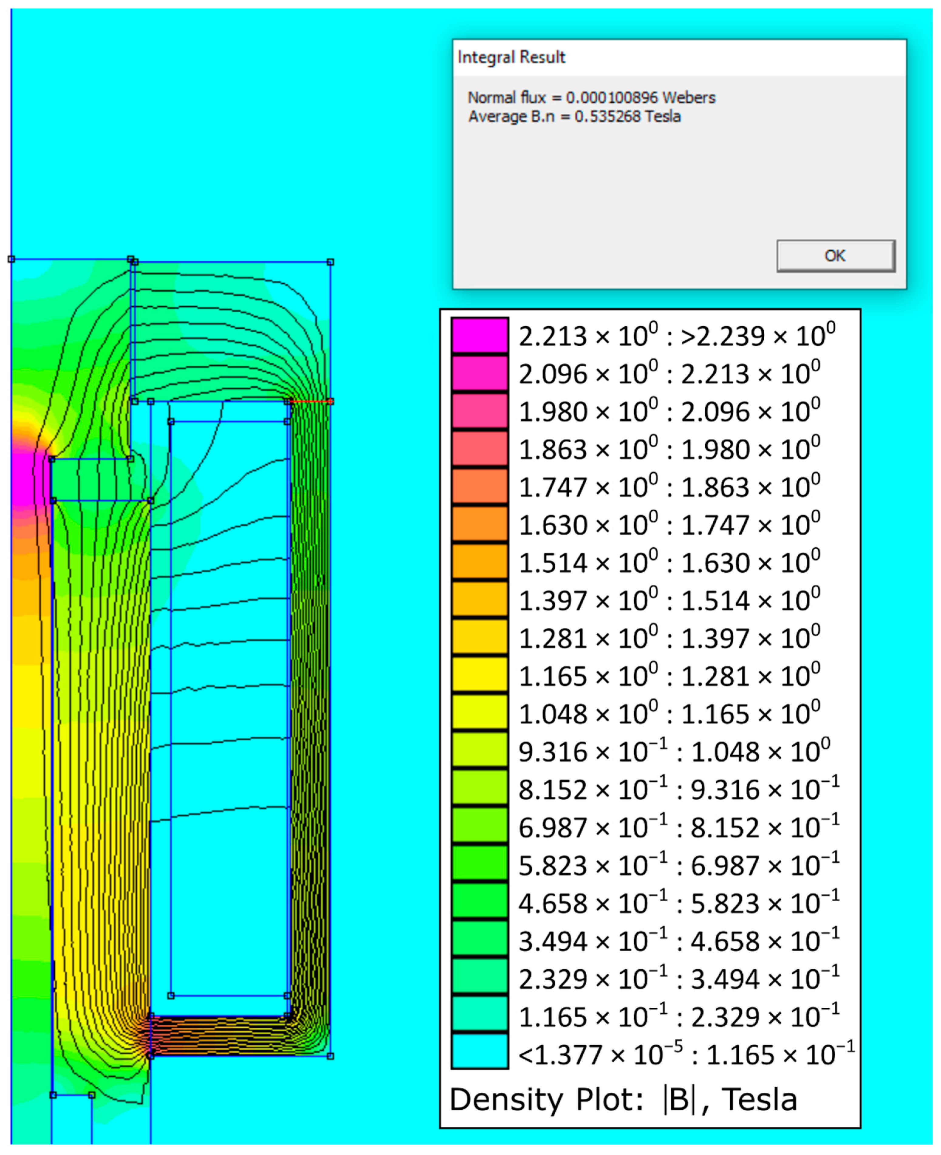
Figure 13 on the left shows the model in the FEMM 4.20 program with the finite element network and defined materials; the right part of the model, after simulation in the postprocessor, shows the magnetic flux lines and colour rendering of the magnetic field intensity, where purple represents the highest intensity. The carcass material, which is in fact plastic, is replaced by air because they have similar magnetic properties.
Figure 14 shows the simulation results for the initial state when the air gap is zero.
Figure 15 shows the simulation results for the maximum air gap condition.
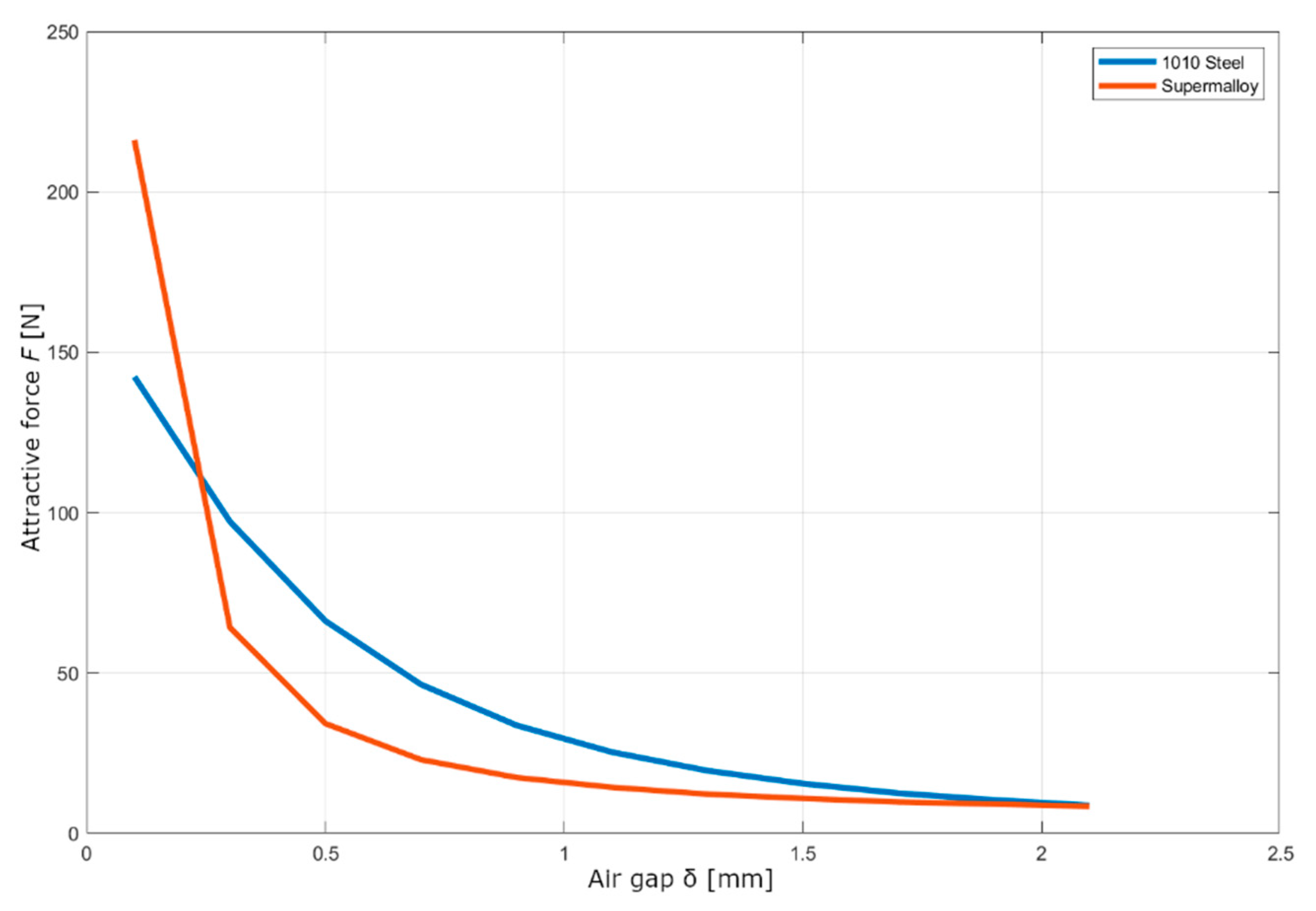
As already mentioned, the main output of the simulation is the characteristic of the attractive force.
Figure 16 shows the characteristics for the two materials mentioned above. It can be seen that the AISI 1010 steel has a more linear course than the Supermaloy steel, which has a sharp break in its air gap area of 0.5 mm but a 50% greater attractive force in the attracted state. The core material AISI 1010 or DIN 1.0413 was chosen for its design, due to greater material availability, lower price and also because the electromagnet from this material has a lower inductance of 0.033 H than the electromagnet from Supermaloy, of 0.068 H.
3.4. Coil Electrical Circuit Design
Because the electromagnet operates with relatively high dynamics, the transients of the coil are important, especially the dependence of the current flowing through the magnetic field on time and voltage. In general, the higher the voltage, the faster the saturation of the magnetic circuit, but if the time of increased voltage is too long, the coil heats up excessively. Therefore, it is necessary to determine how long it takes for the circuit to saturate.
From the previous simulation we know the value of the inductance of the electromagnet, i.e., the inductance of the coil with the inserted soft core, so we can use the following equation to describe the current and voltage:
Assuming that the resistivity and inductance are constant, the equation can be adjusted to these forms by time derivation:
The differential equation [
27] can then be solved using a homogeneous solution:
There is defining initial and final coil saturation conditions. At the beginning, there is zero current; at infinity, the current approaches the constant value given by Ohm’s law:
From which, the constants
C1 and
C2 can be calculated and substituted into the solution:
In this case, we are interested in how long the current value approaches the asymptote
. The value of the approximation can be defined, for example, as:
so we are looking for a current that has a value of 95% of the constant current value.
The equation is, therefore:
where
T is the time sought when the coil will be sufficiently saturated:
These equations apply to the case when the voltage value is equal to the static voltage value at which the coil is rated. However, for faster saturation, it is possible to increase the voltage value after a while. After that, however, the equations compiled above no longer apply, as this is a discontinuous problem. We can partially approach the desired value of the saturation time if we adjust the current equation to the following form:
when the value of the asymptote approximation remains the same, but the course of the exponential curve is adjusted to the new voltage value. The asymptote approximation value is no longer needed because the new curve intersects the static current value.
Instead of an analytical calculation, it is also possible to calculate the original differential equation in the Matlab program, with the current set point.
To describe the state of discharge of the coil, we can use a slightly modified equation, where we will again be interested in the time in which a certain current value is reached; in this case, when it will be equal to zero. Here, too, the principle can be used to use a higher voltage than the nominal one for the transient to speed up the process. However, due to the polarity of the previous charge, it is now necessary to connect a negative voltage that is a multiple of the nominal static voltage of the coil:
All of the above waveforms can be seen in the graph in
Figure 17. The current functions during charging and discharging the coil have the same shape, only mirrored and offset along the horizontal axis. It can be seen that at a higher charging voltage 2
Uref, a faster charge will occur in time
tn2 than at a nominal voltage
tn1. The situation is the same for discharging, only due to the initial conditions, it is necessary to move the discharge at higher voltages along the horizontal axis so that at time
t = 0, the current value is equal to the static value of the coil current. The graph also plots the values of sufficient approximation to the current asymptote, one for charging and the other for discharging the coil.
The resulting selected voltage profile can be similar to
Figure 18; this is a solution where the electromagnet is in a pushing arrangement. The voltage changes abruptly depending on the position of the cam; in the mechanism gripped state, the current is reduced, as not all the force that would be generated by the electromagnet is needed. The reduction in the voltage will bring a smaller value of the generated waste heat in the conductor. To release the needle, it is necessary to demagnetize the entire magnetic circuit, so a negative voltage is applied during demagnetization. Thereafter, the coil is de-energized until just before the point of gripping the needle, when a voltage multiplier is applied, which results in a sharp increase in current. At this point, it is possible to briefly exceed the rated current of the coil to create a value stronger than the rated force of the electromagnet. Then, the stress is reduced again to the initial value; between these two states, it is possible to insert another intermediate stage to achieve the desired characteristics of the attractive force.
The ideal source with a hard characteristic, i.e., with a constant voltage at different loads, is chosen as the voltage source. The voltage of the source is externally controlled so that the optimal behaviour of the whole needle bar system is achieved. It can be assumed that in the real case, the source will not have the ideal designed characteristics and will contain delays and instabilities, which will bring a certain amount of deviation into the system, which must be taken into account.


