Article

Analysis of the Static Performance of a Cableless Aerostatic Guideway

School of Mechatronics Engineering, Harbin Institute of Technology, Harbin 150001, China
*
Author to whom correspondence should be addressed.
Machines 2022, 10(5), 308; https://doi.org/10.3390/machines10050308
Submission received: 24 March 2022 / Revised: 22 April 2022 / Accepted: 24 April 2022 / Published: 26 April 2022
(This article belongs to the Section Friction and Tribology)

Abstract

:
To develop an innovative aerostatic guideway without cable drag force that can be widely applied to ultra-precision machining and measurement technology, it is necessary to analyze the static performance of the aerostatic guideway. The structural properties of the cableless aerostatic guideway, i.e., the bearing capacity and internal pressure distribution, directly affect the accuracy of processing and measurement. In this work, the relevant flow equations of the cableless aerostatic guideway are established by considering the unbalanced micro-scale air film. Moreover, the finite difference method is used to solve the calculation of the global analysis of air film at different positions. In addition, this work compares and analyzes the pressure and fluid velocity vector distributions in balanced and unbalanced states and investigates the effect of varying the thicknesses of the air film on static characteristics such as bearing capacity and stiffness. By comparing the balanced and unbalanced states under the same conditions, the obtained results show that in the unbalanced situation, the bearing capacity is lower by 11.69 percent and the stiffness is slightly higher (by 16.67 percent). Furthermore, the related experiments verify the predicted dependence of the bearing capacity on the thickness of the air film, and further demonstrate the feasibility of the proposed structure of the cableless aerostatic guideway. This work provides a technical reference for the design of a cableless aerostatic guideway.

1. Introduction

Ultra-precision machining and measurement technology rely on high-quality linear motion to achieve high-precision positioning [1,2,3,4,5,6]. The ultra-precision positioning stage, as a typical system component, provides ultra-precision linear motion. Likewise, aerostatic guideways are widely used in ultra-precision positioning stages as the support components with extremely low frictional resistance, ultra-high precision, and long service life [7]. However, due to the limitation of the small damping coefficient of the aerostatic guideway, its accuracy is easily affected by external interferences.
The interferences encountered by the moving part of the aerostatic stage include the output disturbances of the driving system (such as thrust fluctuation of the motor [8]), cutting force caused by the cutting tool, and external interference force during machining). In addition, the cable force corresponds to a kind of interference caused by the motor cables and intake tubes. In traditional aerostatic stages, the slider is used as a moving part to mount the air cavities and linear motor primary coils. Therefore, the cables and tubes are also linked to the slider with a flexible hinge. During operation, the flexible hinge moves with the slider and induces a cable force.
Furthermore, the movement accuracy of the ultra-precision aerostatic stage is also influenced by the installation of flexible cables and other problems. The slider of the aerostatic stage is disturbed by the pulse forces caused by cables when the slider moves to certain positions (i.e., when the flexible cable is in some certain position). The significant influence of such disturbances on the motion accuracy cannot be ignored in ultra-precision procession. However, the literature focusing on eliminating the cable force interference in ultra-precision manufacturing is scarce. Moreover, the effect of the cable force can be eliminated in theory by changing the structure of the guideway. Accordingly, this paper proposes a structure of an aerostatic guideway without the cable force. The electrical system and the gas supply system are indispensable in an aerostatic positioning stage, but the cables and tubes can be fixed to the guideway base to avoid the movement. This can be achieved by mounting the motor primary coils and air cavities on the base.
In the proposed structure, an effective air film is generated between the slider and the guideway, which moves with the guideway. The positions of throttle orifices on the air film will change continuously if the film is considered as a reference. Besides, two limit states are used to express the most stable and unstable cases of the air film. Meanwhile, the performance is not fixed (i.e., the performance of the aerostatic guideway always spans between the two limit states), and the static analyses of the cableless structure are necessary. Essentially, the fact that the guideway operates normally at the limit demonstrates the feasibility of a cableless structure.
The main task of static performance analysis is to obtain a simple yet accurate mathematical model. At present, the research on the static characteristics relies on different numerical analysis methods. For instance, G. Belforte [9] performed a numerical analysis on the feeding system of externally pressured gas bearings and corrected the theoretical mass flow equation with a discharge coefficient. Similarly, J. Zhang [10] used the “separation of variables” to solve the laminar boundary layer equations and investigated the effects of supply pressure, orifice diameter, and air film thickness on the pressure depression. In the study reported by Miyatake [11], the computational fluid dynamics (CFD) method was used to determine the flow coefficients of small feed holes, and the finite difference method (FDM) was used to obtain the bearing characteristics. In another work, Charki A. [12] solved the nonlinear Reynolds equation using a finite element modeling method to calculate the stiffness and damping characteristics of thrust air bearings with multiple orifices. Secondly, the influence of the micro-scale cannot be underestimated. In this regard, Eleshaky [13] highlighted that for the value of a Knudsen number greater than 0.05, the gas flow is of a slip flow type and is prone to velocity slip. This condition was satisfied on the microscopic scale, and hence, velocity slip must be considered when analyzing the gas flow. Chen [14,15] studied the effect of errors caused by microscale gas film on the static and dynamic performances of a shaft supported by aerostatic bearings and analyzed the influence of factors related to the micro-scale on the performance of an aerostatic guideway.
In addition, the dimensional parameters of the aerostatic guideway have a significant influence on its static performance. Many researchers attempted to optimize the relevant structures. Y. Li [16] investigated the influence of different geometrical parameters of aerostatic thrust bearing on its load carrying capacity, stiffness, mass flow rate, and maximum gas velocity, as well as the optimized design of the bearings. Gao [17] studied the performance variation of aerostatic thrust bearings due to different chamber shapes, and concluded that the pressure depression, gas vortices, and turbulent intensity are all weakened with the decreasing air film thickness. Moreover, Chen [18] analyzed the effects of bearing length/diameter ratios, restrictor types and sizes, and supply pressures on the structural stiffness of aerostatic journal bearings. In another attempt, Cui [19] demonstrated the impact of restrictor characteristics on the stability and stiffness of hydrostatic circular pad bearings. Belforte G. [20] studied the effect of machining circumferential grooves in a pad surface on pressure distribution, airflow, and stiffness.
Based on the above-mentioned factors, in this paper, the variations in the static performance of aerostatic guideway caused by the structural variations induced by a new cableless structure are studied. First, the traditional Reynolds equation is modified based on the limit states to derive the gas flow model. Next, the distributions of air cavities’ inlet pressure are used to calculate and compare the stiffness and bearing capacity of the aerostatic guideway in two limit states. Finally, the bearing capacities of the aerostatic guideway are tested at different air film thicknesses, and the errors between the two limit states’ test values and simulated values are extracted. This work constructs a theoretical basis for designing a cableless aerostatic guideway and builds the foundation for improving the locational accuracy of stages in the future.

2. The Mathematical Model of Air Film Flow

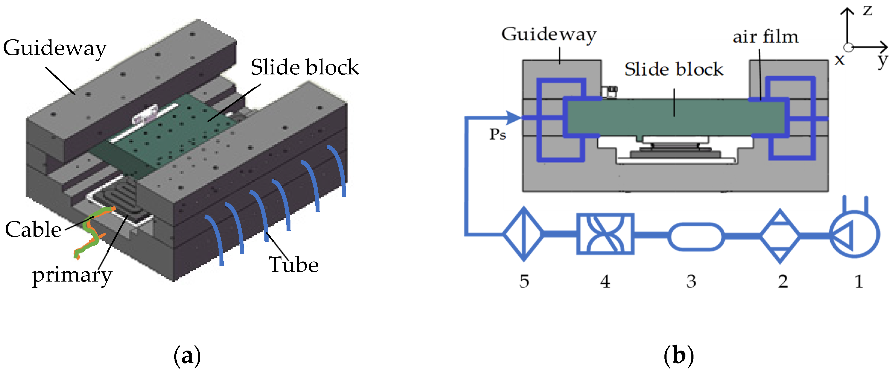
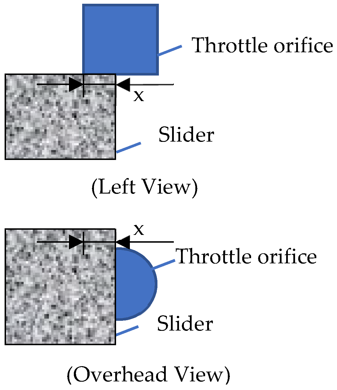
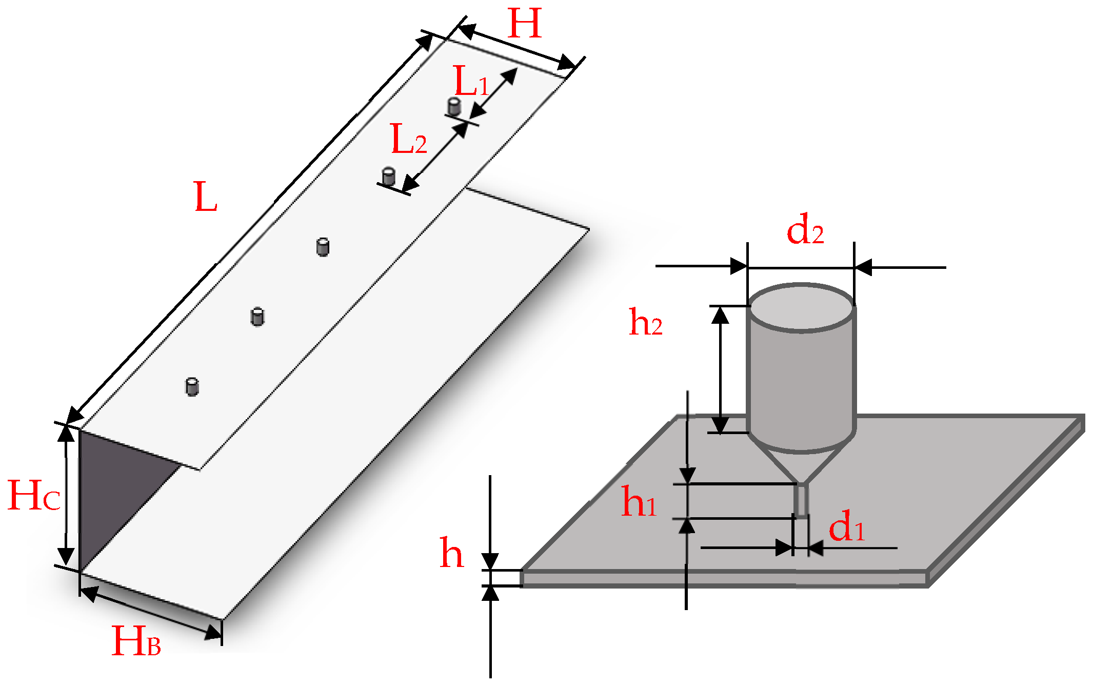
2.1. The Structure and Operational Principle of the Aerostatic Guideway

The simplified structure model and operational principle of the positioning stage are shown in Figure 1. As seen in Figure 1a, the structure of the ultra-precise aerostatic positioning stage is closed, where the moving part is the slide block and the fixed part is the guideway. There is a gap between the slide block and guideway, forming an air film, which plays a supporting and guiding role. Meanwhile, the drive cables and intake tubes are fixed to the guideway to achieve motion without any cable force interference. In this aerostatic positioning stage, orifices are distributed inside the guideway. During the movement of the mover, the slider repeats the entry and exit of the throttle orifices. Figure 1b illustrates the operation of the aerostatic guideway. Air, a compressible gas compressed using an air compressor and dried by the air dryers, is stored in a gas tank. The pressure of compressed air is regulated using a flow control valve and the impurities are removed using a filter. The compressed air then enters into the air inlets of the aerostatic guideway. When the air cavities are filled with the compressible air, an air film is formed between the guideway and the slide block. This air film possesses supporting and lubricating capabilities, and thus, the stage can be used as a support for workpieces and measuring equipment in production processes and testing methods.

2.2. The Governing Equations of the Fluid Flow

According to the flow characteristics of the air film in the aerostatic guideway, a simple and effective fluid model should be built.
In the fluid analysis of a conventional aerostatic guideway, the throttle orifices are symmetrically distributed in the x-direction of the gas film (called the balanced condition), as shown in Figure 2a. However, owing to the characteristics of the cableless structure, the effective part of the air film moves with the slider and the throttle holes do not always display a symmetrical distribution (referred to as the unbalanced condition). During the slider movement, there will be several situations where five throttle holes will be fully covered, while the sixth throttle hole will be only partially covered. The limiting case is where the slider enters a throttle and covers half of the throttle orifice. The relevant state of the air film is shown in Figure 2b. The above demonstrates the two extreme states of the air film in a complete stroke of the slider movement. Herein, these two conditions are analyzed separately.
To simplify the calculation and guarantee the calculation’s accuracy, the aerostatic guideway model works on the following assumptions:
  • The flow is isothermal, the gas viscosity is constant, and the air is an ideal gas.
  • The flow is parallel to the wall and only changes in the direction of the vertical wall.
  • There is no pressure gradient in the flow direction and no chemical action on the wall.
  • The inertia force is too small relative to the damping force and gravity, and the effect of the fluid inertia force is ignored.
In this work, the aerostatic guideway adopts the small hole orifice restrictors to obtain a better static stiffness. The air flow should satisfy the flow conservation equation, and the fluid flow entering into each orifice of the aerostatic guideway is the same as the flow moving out of the air film gap boundary. This is expressed by Equation (1) as:
Q i n = Q o u t
In the fluid dynamic analysis, the flow through the throttle orifices follows Equation (2):
Q m = 0 . 3383 d 1 2 2 ρ 0 p 0 [ ( p p 0 ) 1.42 ( p p 0 ) 1.71 ] 1 2
where Q i n is the flow entering into the air film gap from the orifices, Q o u t is the flow moving out of the air film gap into the external environment, and Q m is the mass flow passed through an orifice. Meanwhile, ρ 0 and p 0 are the external gas supply density and pressure, respectively. Similarly, ρ and p are the density and pressure in the air cavity, respectively.
When the state of air film is changing, at least five throttle orifices work properly. When the slider covers the throttle hole partially, a portion of compressed air flows into the small air gap and then to the supported slider as air film, and the rest flows out from the unshaded hole. In addition, the air film is very thin, and the corresponding air flow behaves differently compared to a typical macro-scale air flow (gas flow state and performances are different in the micro-scale and macro-scale). Interestingly, phenomena such as velocity slip rarefaction effect and variation in viscosity of the air film appear at the micro-scale. Accordingly, the usual Reynolds equation is unable to describe the attributes of fluid flow in the actual situation. Therefore, as shown in Figure 3, in this unbalanced condition, when the length of throttle orifice covered by the edge of slider is x, the total flow entering into the air film gap is Q i n , as expressed in Equation (3):
Q i n = { 2 . 0298 d 1 2 2 ρ 0 p 0 [ ( p p 0 ) 1.42 ( p p 0 ) 1.71 ] 1 2 , ( b a l a n c e ) 1 . 6915 d 1 2 2 ρ 0 p 0 [ ( p p 0 ) 1.42 ( p p 0 ) 1.71 ] 1 2 + [ ( x d 2 ) ( d x x 2 ) 1 2 + d 2 4 arccos ( 1 2 x d ) ] 2 ρ 0 p 0 , ( u n b a l a n c e )
Meanwhile, Q o u t is the total flow out of the air film gap, expressed as:
Q o u t = h 3 ρ 12 η [ L ( | p y | y = 0 + | p y | y = H ) d x + H ( | p x | x = 0 ) d y ]
The increased mass in the fluid micro-element is equal to the net mass flow into this micro-element per unit of time. According to the Law of Conservation of Mass, we analyze the flow problems using Equation (5):
ρ t + ( ρ v x ) x + ( ρ v y ) y + ( ρ v z ) z = 0
There are three coordinates: x-direction, y-direction, and z-direction, and vx, vy, and vz are the velocity components in the corresponding directions. By simple organization, the general form of the Navier–Stokes model can be expressed as:
x ( h 3 p p x ) + z ( h 3 p p z ) = 6 η [ 2 ( p h ) t + V x ( p h ) x ]
Here, η is the viscosity coefficient of gas, Vx is the velocity in the moving direction of the slide block (x-direction), t is the time, and h is the thickness of air film along the y-direction.
On the microscopic level [21], fluid flow is classified according to the Knudsen number as the ratio of the molecular mean free path ( λ ) to the minimum channel height ( h ):
k n = λ h
In this model, λ = 6.8 × 10 5 mm because k n = 0.0065 , the Knudsen number is between 10−5 and 10, and the fluid can be considered to be in the state between continuum flow and free molecular flow.
The slip occurs in the gap between the slide block and the guideway that changes the velocity vector of the air, and the velocity slip is u a . In addition, the performance of the velocity slip in the gap can be reflected by the slip length, and this could be calculated by a tangent vector coefficient. By simple generalization, the slip length L = 5.33 × 10 5 mm.
The model of velocity slip is described by Equation (8) as:
( v x v y v z ) = { ( V x + u a l v z y 0 ) = ( V x + l v x y l v z y 0 ) = ( V x + 5.33 × 10 5 × v x y 5.33 × 10 5 × v z y 0 ) , y = 0 ( u a l v z y v x h x + v y h z ) = ( l u y l v z y v x h x + v y h z ) = ( 5.33 × 10 5 × v x y 5.33 × 10 5 × v z y v x h x + v y h z ) , y = h
When the gas flows in a thin gap, for the slip model, viscosity changes with the increasing wall shear stresses. For accurately analyzing the model, the traditional Reynolds equation needs to be modified. Here, the flow factor is introduced as Q, which selects the difference equations according to different gas rarefaction and slip states.
To tailor the Reynolds equation model for thin gas films for high precision, consider the effect of the flow factor on the air film in x-direction. By substituting Equation (8) into Equation (6), the following Equation (9) can be obtained:
x ( Q h 3 p p x ) + z ( h 3 p p z ) = 6 η [ 2 ( p h ) t + V x ( p h ) x ]
where D is an inverse Knudsen number defined as D = p h 2 R T / μ . Because of the difference in the value of D, the factor Q can be expressed as different linear Equations [21]. Meanwhile, T is the characteristic temperature and R is the gas constant.
In this model, D = 10.9589 and Q = 0.96904 + 6.95964 / h .

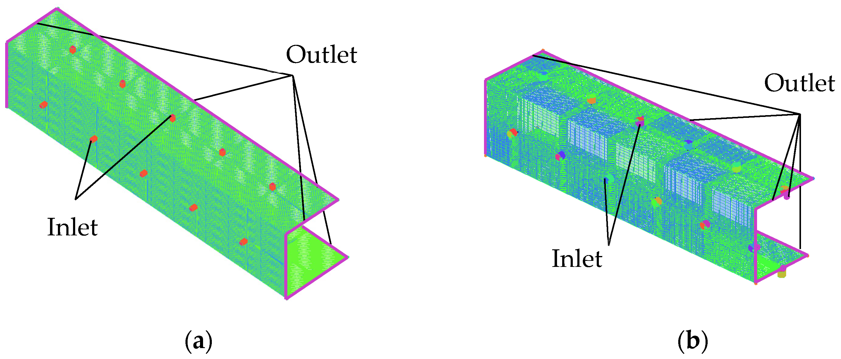
2.3. Boundary Conditions

The boundary conditions must be defined prior to solving the model.
  • Pressure boundary condition
The pressure at six out boundaries of air aerostatic guideway with respect to the outside world is 1 atmospheric pressure (0.1 MPa). There are n throttle orifices in the aerostatic guideway, where the outlet pressure of mth throttle is p m .
  • Temperature boundary condition
The gas temperature is equal to the wall temperature.
  • Symmetric boundary conditions
The structure of the aerostatic guideway is symmetrical around the y-axis, and to improve the efficiency of the solution, we chose half of the guideway as the object to be solved.
The governing equation is discretized on uniform grids by utilizing the finite difference method. Besides, the discretized control equation is solved via finite difference iterative calculations. In this study, the supply pressure and the structural dimensions of the aerostatic guideway are first set. Next, the solution area is meshed into n regions, where each region contains a throttle. In this way, the solution region m has the mth throttle. Moreover, in solution region m, pm is the outlet pressure of the mth throttle orifice, Q m is the flow into the mth throttle, and Q m o u t is the flow out of the region. In this case, the amount of pressure change is Δ p . The dichotomous method is used to reduce the difference interval of the flow between the inflow and outflow to accelerate the convergence. The performance calculation flow chart for the aerostatic guideway is provided in Figure 4.
Given the initial conditions, the mass flow is calculated using the over-relaxation iterative method. After several iterations, the discrete pressure distribution can be expressed as a continuous distribution. The solution converges when the absolute value of the difference between Q m / Q m o u t and 1 is less than the flow error ε (convergence precision). The value of ε used in this work is 10−6.

3. Results and Discussion

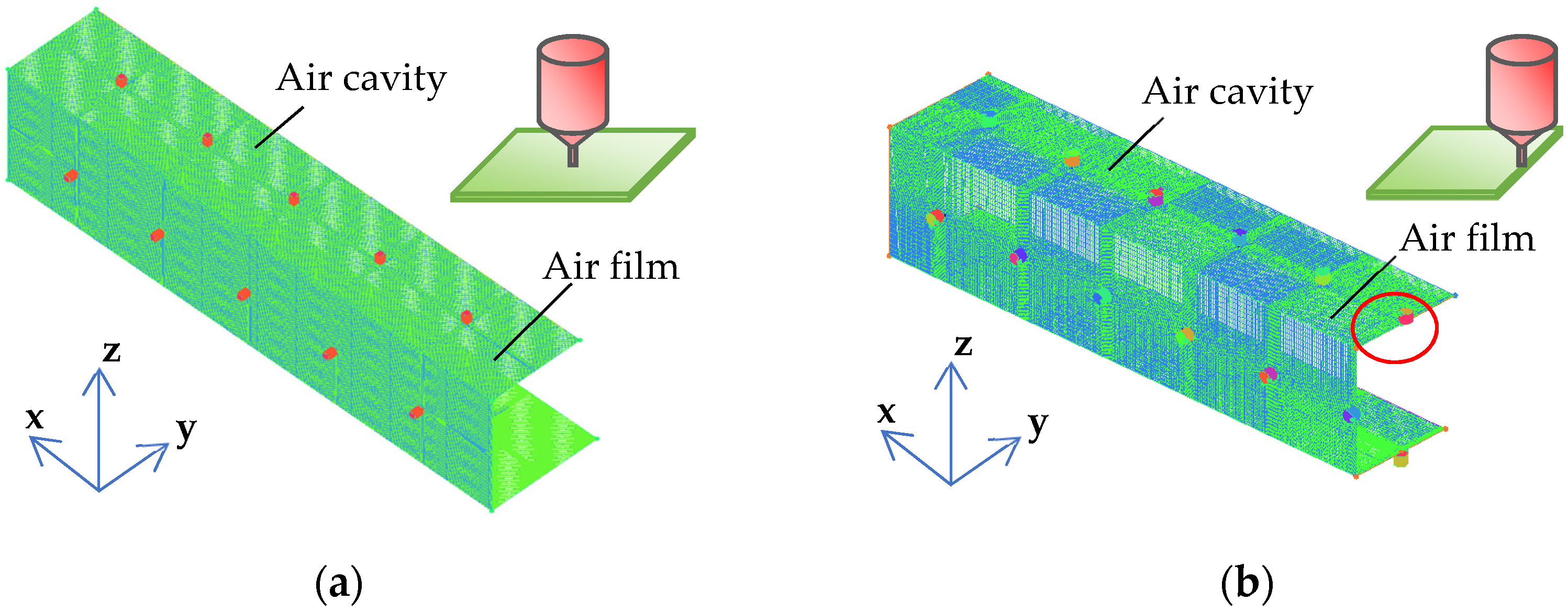
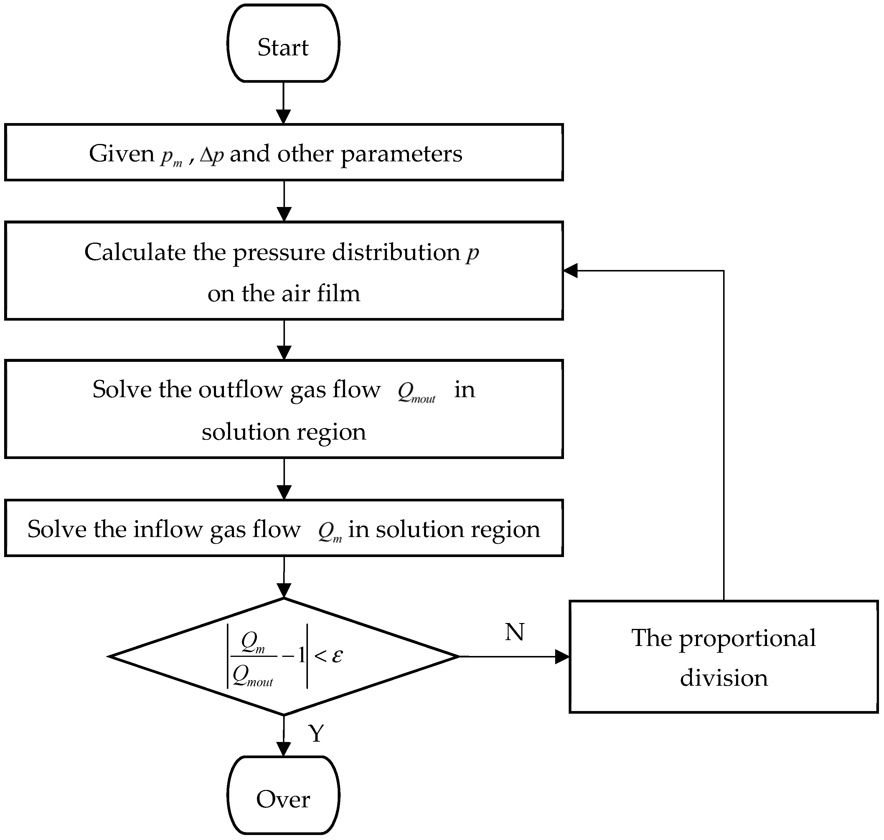
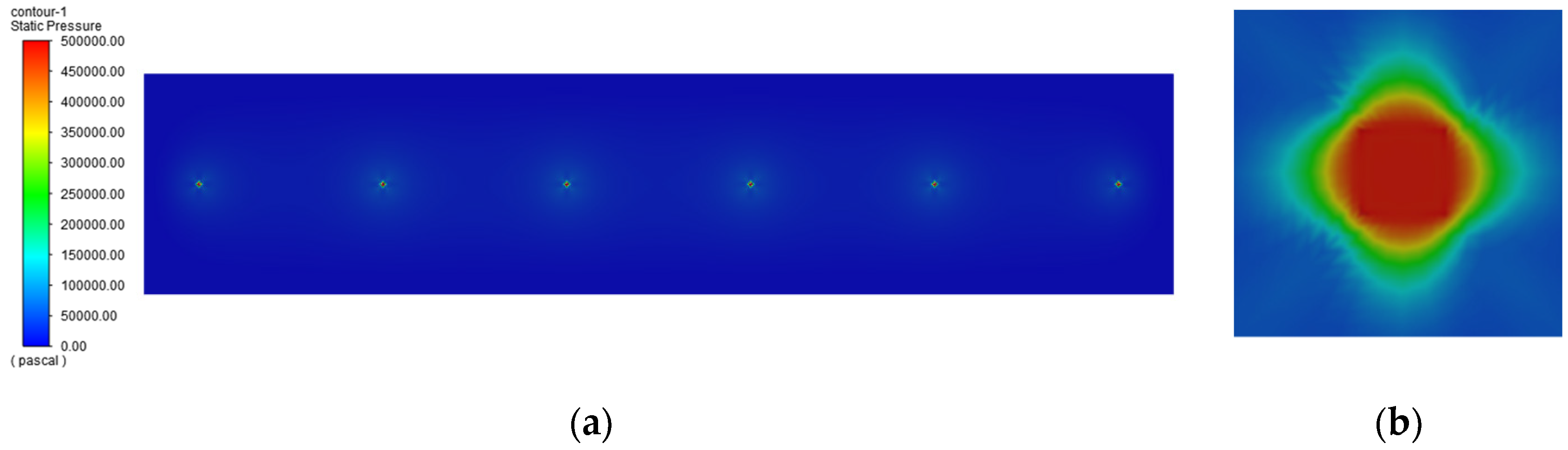
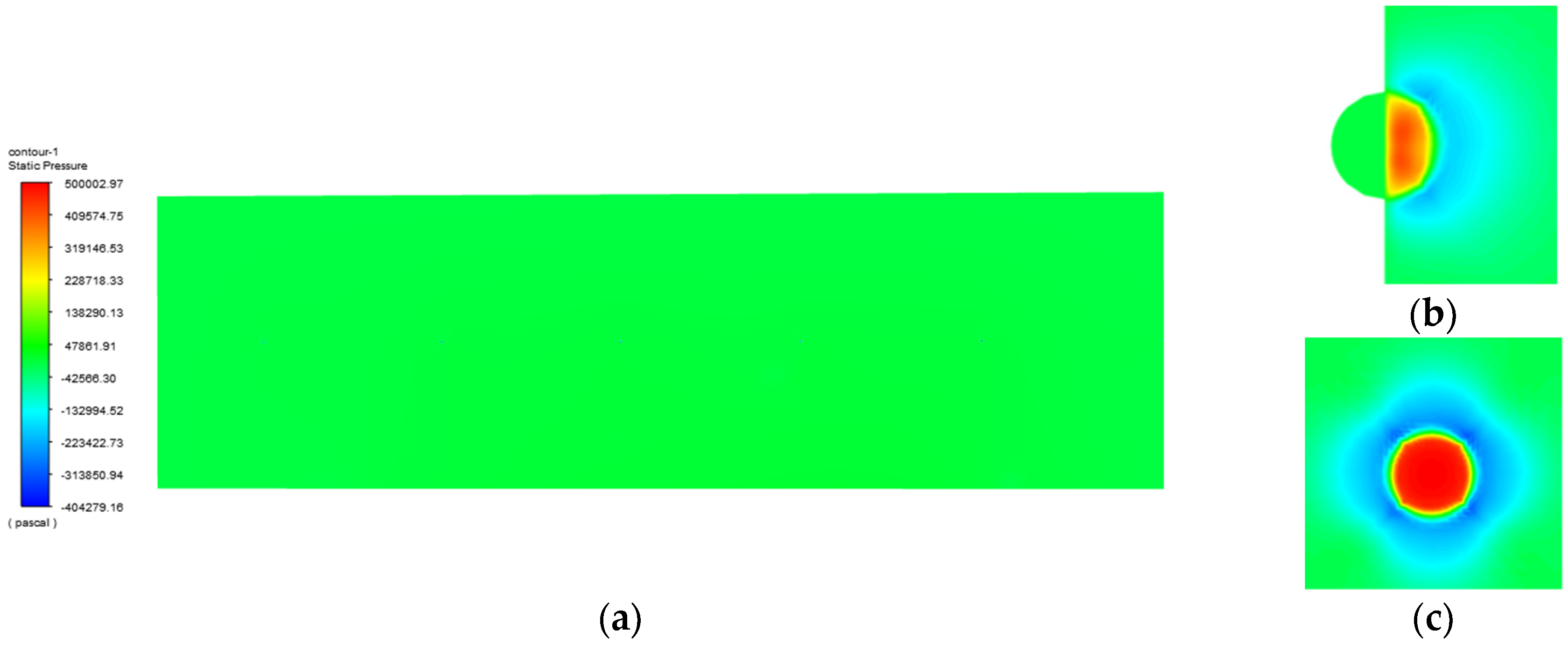
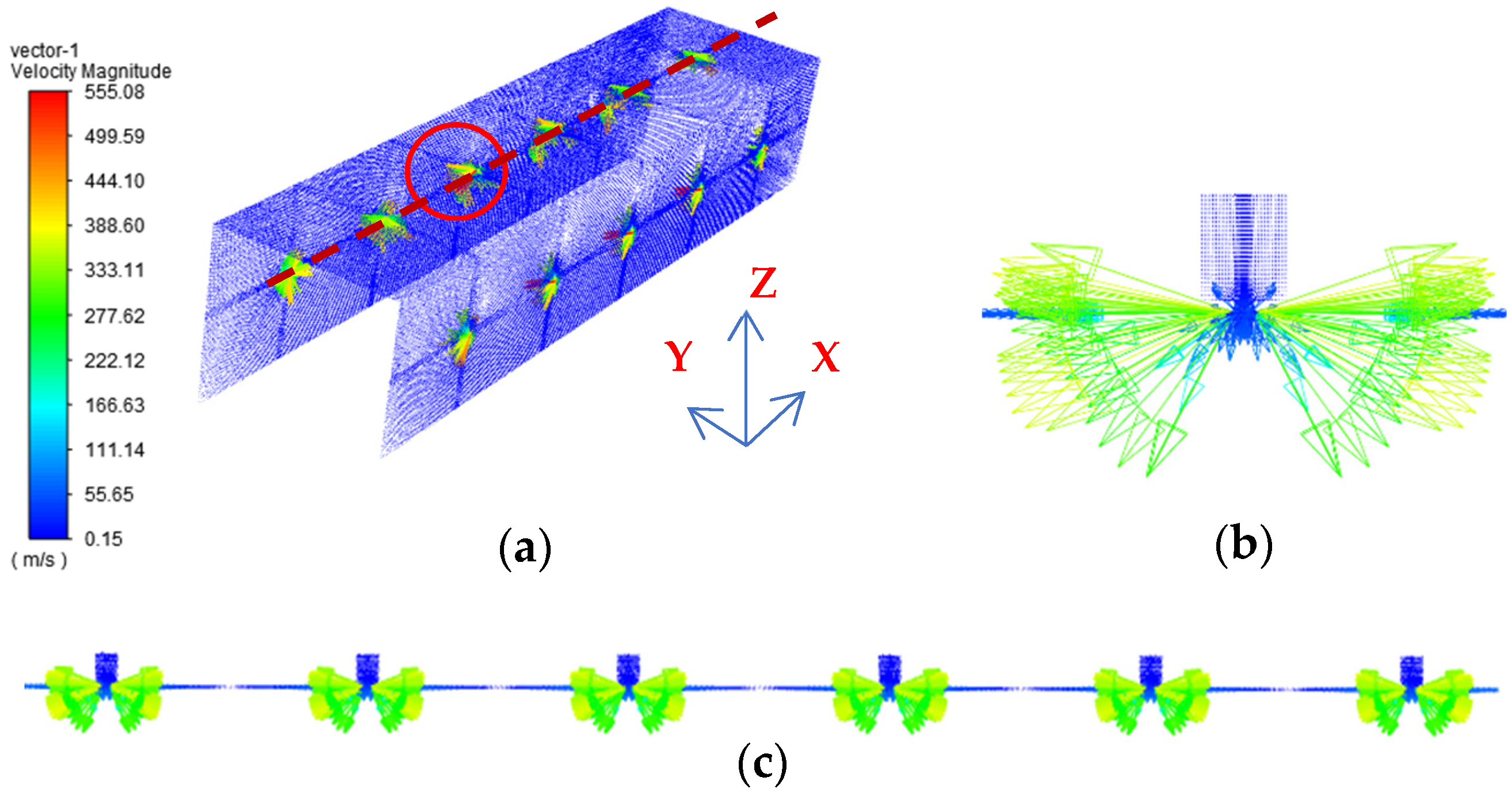
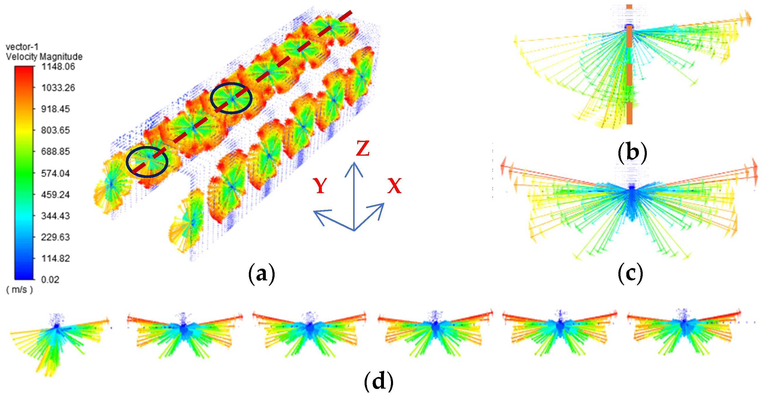
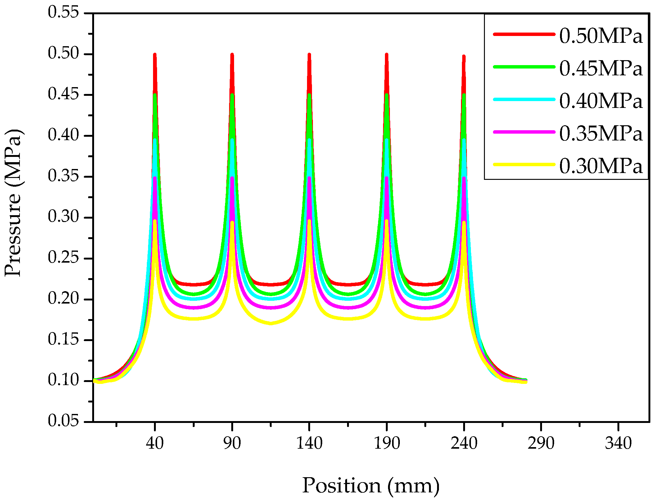
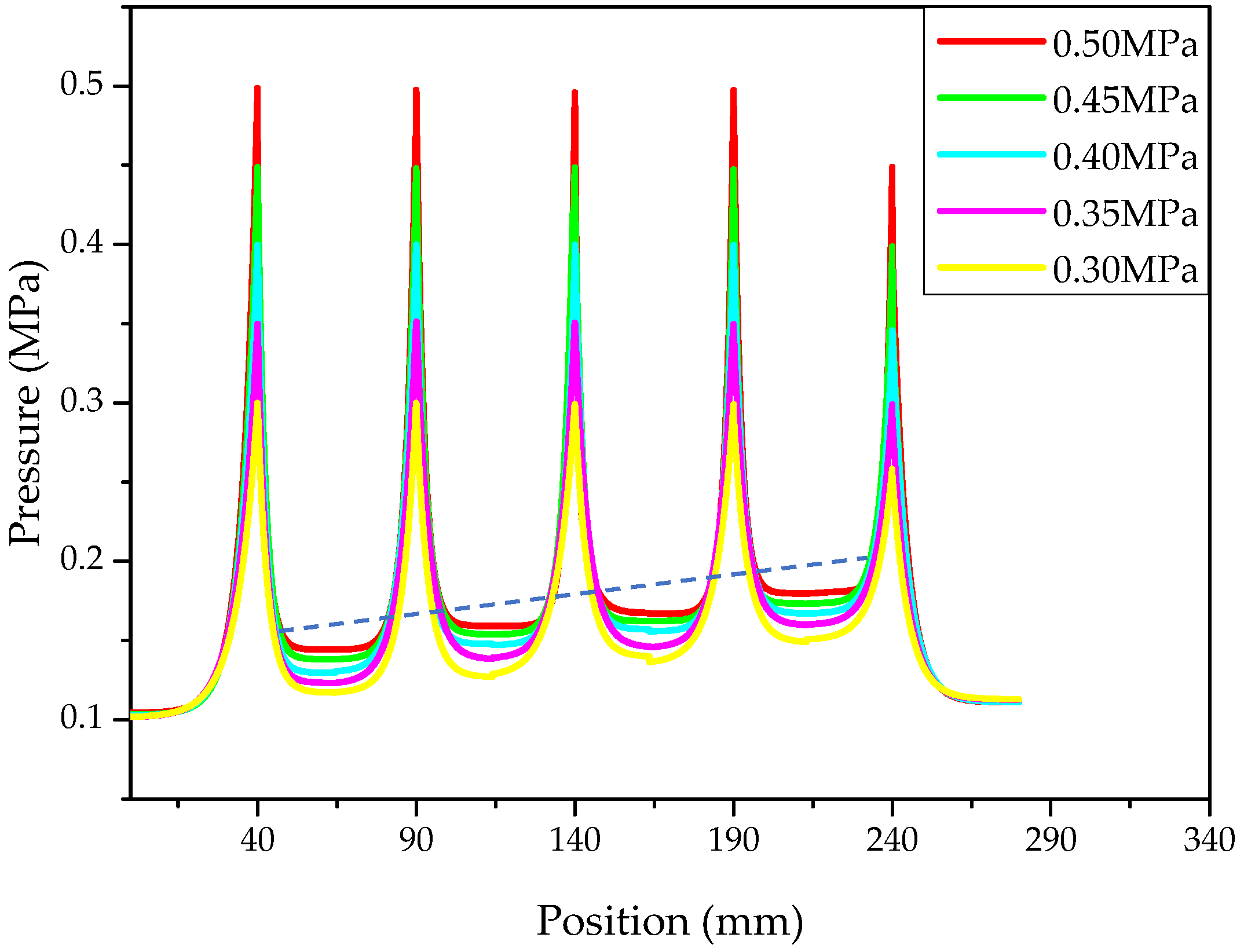
3.1. The Calculation and Analysis of the Pressure Distribution of Air Film

To investigate the static performance of a cableless aerostatic guideway, a CFD analysis simulation model is built using ANSYS FLUENT software (Ansys Student 2020 R2, Harbin, China). Through simulation analysis, the pressure distribution and air velocity vector characteristics of the air film are studied. At this stage, the independence tests are carried out on the computational mesh to ensure the reliability of the computational results.
Figure 5 shows the models of balanced and unbalanced air films with defined boundary conditions. Each air cavity entrance is defined as the inlet. The four narrow sides of the air film are defined as the outlets in the balanced state, as demonstrated in Figure 5a. Nevertheless, when the air film is in an unbalanced condition, the outlet includes the above-mentioned four narrow sides and three semicircles of the throttle holes that are not covered by the slider, as shown in Figure 5b. Since achieving high-precision simulation results requires high quality meshing, proper adjustment of the mesh is necessary to ensure the convergence of the calculation and to speed up the calculation. The calculated results for the value and standard deviations of air film force only change slightly with the changing density of the mesh. The validity of the model is verified. In this model, the supply pressure range of the inlet is 0.3 MPa to 0.5 MPa, whereas the atmospheric pressure is specified at the outlet.
In this model, compressed air is applied between the guideway base and the slider block to form an air film, where the length of air film is equal to the length of slider. As Figure 6 shows, HA, HB, and HC are the breadths of the three surfaces of the air film (top, bottom, and lateral surface). Moreover, L1 is the distance from the air film edge to the nearest orifice hole on the inside of the air film, which changes with the movement of the slider. When L1 is equal to 40 mm, the air film is in a left–right balance. The distance between the two adjacent orifice holes is L2, and the number of orifice holes covered with air film is five or six during the stroke. The thickness of air film is equal to the distance between slider and guideway base. While ignoring gravity and without any load on the aerostatic guide, the air film area is of uniform thickness. The average thickness of the air film on the surfaces is h, the sum of thicknesses of upper and lower surfaces air film is 20 μm, and the air film thickness of left and right side surfaces is 10 μm. Furthermore, the external load leads to a change in air film thickness (the variation is e), and the eccentricity ratio is ε = e / h . For ε = 0 , the structural parameters of the model are listed in Table 1.
According to the finite difference method, by combining the structural parameters, such as air cavity and throttle of aerostatic guideway, and considering the factors for various slider positions, the pressure distribution of the air film is determined by solving the Reynolds equation. When the input pressure is 0.5 MPa, the corresponding pressure distribution is as shown in Figure 7 and Figure 8.
In Figure 7, the slider is moved in the balanced position where it covers six orifice holes and both sides are equidistant from the nearest holes. As evident in Figure 7a, the maximum pressure in the air film surface is at the inlet of throttle orifice, and the pressure decreases gradually with the increasing distance from the orifice, where it eventually adopts an even distribution. From Figure 7b it can be seen that the pressure distribution near the orifice hole exhibits a flower-petal-like shape.
Nevertheless, when the air film structure is asymmetrical, the pressure distribution changes compared with the scenario elaborated above. At this time, there are five throttle holes fully covered and one throttle hole half covered by the slider block, as shown in Figure 8a. For this case, the pressure distribution around the half-covered hole is plotted in Figure 8b. In this position, the air cavity is the inlet to input the compressed air and the area of throttle hole not covered by the slider serves as the outlet. The air pressure at the half-covered throttle orifice is slightly lower compared with the others, and a semi-ring-shaped, low-pressure area is formed near the half-covered throttle hole in the air film. Moreover, Figure 8c shows the pressure distribution near the fully covered throttle orifice hole in the unbalanced condition. The pressure is highest at the throttle hole; meanwhile, a petal-shaped, low-pressure zone is formed outside the hole. By moving away from the low-pressure areas, the pressure gradually increases to a steady state, as can be seen in Figure 8a. By comparing Figure 7 and Figure 8, it can be concluded that at the same supply pressure, the surface pressure of air film is higher in the balanced condition.
The whole airflow velocity vector distribution in the balanced condition is shown in Figure 9a, with an air supply pressure of 0.5 MPa. Figure 9b shows the flow velocity phenomenon near the throttle hole, where the highest flow velocity is observed at a position close to the hole and the flow velocity decreases with the increasing distance from the hole. The velocity on the central symmetric surface of the air film is distributed periodically, as shown in Figure 9c. The flow rate is uniform and stable.
In the state of extreme imbalance, the velocity vector diagram for the overall air film flow at a supply pressure of 0.5 MPa is shown in Figure 10a. The average velocity of the unbalanced air film is significantly higher than the balanced one. Moreover, the flow velocity distribution near the half-covered throttle orifice at the edge of slider is different from that near the other completely covered throttle orifices. The flow rate at the edge position of the throttle hole is shown in Figure 10b, where a part of the air is runoff from the uncovered part on one side. Meanwhile, on the other side, it flows into the air gap to form an air film to support the slider moving with low friction. In addition, Figure 10c displays the flow rate around the fully covered throttle orifice. The comparison of these results reveals that the air velocity at the special throttle orifice is lower than the flow velocity near the fully covered throttle orifice. Furthermore, Figure 10d illustrates that the velocity is higher near the throttle holes and lower in the regions far away from the throttle holes. Lastly, the unbalanced air film is also distributed periodically, except at the special edge.
Evidently, from Figure 9 and Figure 10, the maximum flow velocity in the unbalanced state is greater than that in the balanced state; however, no cyclone appears at the outlet of the throttle holes.
The pressure distribution on the surface with different supply pressure values is shown in Figure 11 and Figure 12. While the air film is in balance, as indicated in Figure 11, the maximum surface pressure occurs at the positions near all six throttle orifice holes. The results show that the pressure value follows a parabolic trajectory, while moving from one throttle hole to other adjacent throttle hole. As the displacement increases, the pressure reduces gradually, and the pressure value is lowest when the distance from the first hole is L2/2 mm. As the displacement continues to increase until L2, the pressure of the gas film starts increasing, and finally, the maximum pressure occurs at the second hole (i.e., the adjacent hole). Besides, the pressure distribution of the air film in the direction of the slider movement is distributed periodically. Furthermore, with a decrease in supply pressure, the average pressure on the surface of the air film reduces.
In contrast with the above scenario, the air film pressure situation changes in the unbalanced condition, which can be readily visualized from Figure 12. The pressure is highest at the fully covered throttle orifice holes, while the pressure at the location of special half-covered hole is about 0.05 MPa lower than the maximum value. The average pressure in an unbalanced state is lower than that in a balanced state. Owing to the relatively complex gas movement at the special location, the pressure near the fully covered hole immediately adjacent to the special location (the position at 230 mm) is higher than the other areas. The pressure distribution of the air film is slightly biased in the unbalanced state.

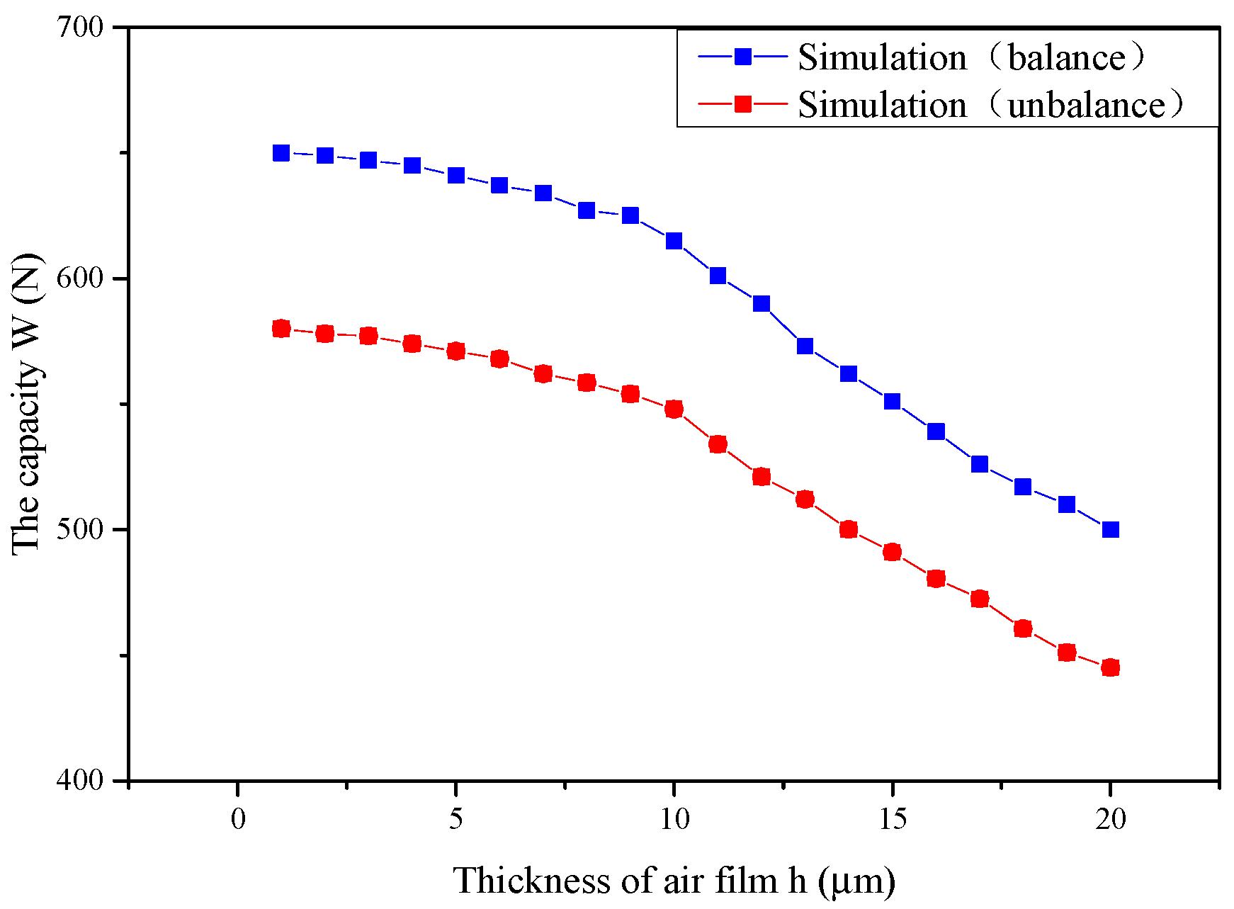
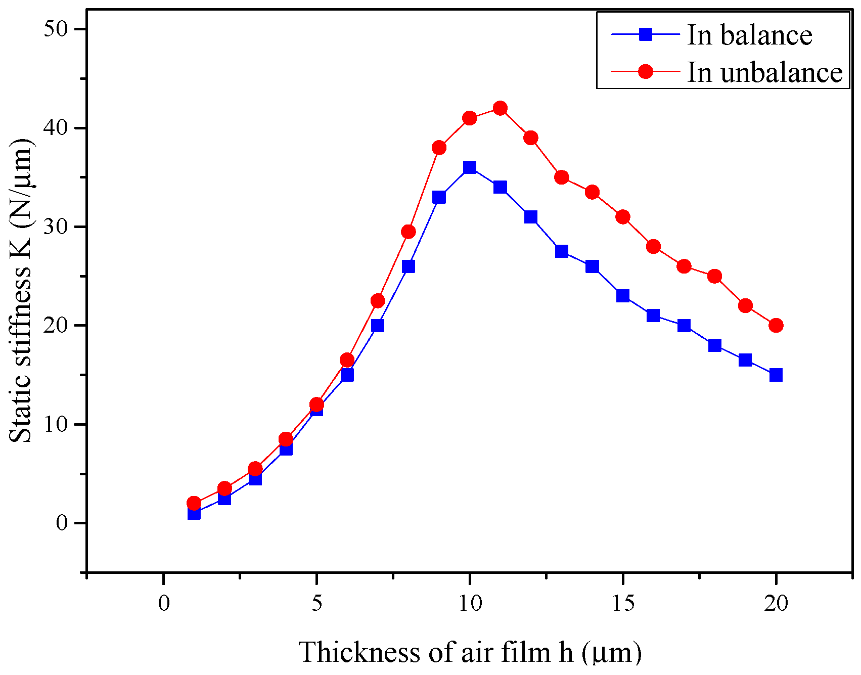
3.2. The Analysis of the Static Performance of the Aerostatic Guideway

Based on the distribution of gas pressure, Equation (10) can be utilized to derive the bearing capacity of aerostatic guideway, as follows:
W = N × A p d A
where A is the area of air cavity, N is the number of air cavities, and p is the distribution of gas pressure. The static stiffness of the aerostatic bearing represents the degree of change in the bearing capacity as the thickness of air film changes. The following equation can be used to determine the static stiffness:
K = W h 1 W h 2 h 1 h 2
where K is the static stiffness of the aerostatic guideway, W h 1 and W h 2 are the bearing capacity values corresponding to two different thicknesses, and h1 and h2 are the two different upper air film thicknesses.
Figure 13 compares the bearing capacities calculated in different states. It can be seen that the bearing capacity in a balanced state is always higher than that in an unbalanced state, and with the increasing thickness of the upper air film, the bearing capacity reduces. At maximum, the bearing capacity of the aerostatic guideway in the unbalanced condition is 11.69 percent lower compared to that in the balanced condition.
Figure 14 shows the comparison of the static stiffness values calculated for different states. It can be seen that the static stiffness in the unbalanced condition is higher than that in the balanced condition at the same upper air film thickness. This is because the low-pressure zones exist immediately adjacent to the throttle holes when the air film is in the unbalanced state. In addition, with the increasing thickness of the air film, the static stiffness rises and then drops. The inflection point of the stiffness curve in a balanced state occurs when the thickness of an air film reaches 10 μm, while the inflection point for an unbalanced state occurs at an air film thickness value of 11 μm. The variation in the static stiffness is caused by the rarefaction effect of the air film, which improves the stability of aerostatic guideway when the gap generating the air film is small. Meanwhile, the maximum stiffness in an unbalanced state is higher by 16.67 percent relative to a balanced state.

4. Verification of Experimental Results

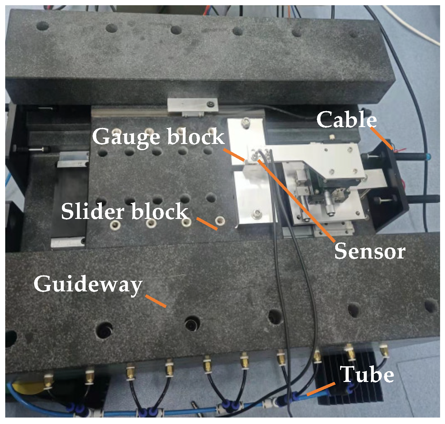
4.1. Equipment and Method

To verify the accuracy of the simulation, the bearing capacity experiments were performed on an aerostatic guideway. The variations in air film thickness and load forces were measured through tests. In this experiment, an eddy current sensor was used to collect data on the micrometric displacement, and the sensor resolution was 0.02 µm. As an external load, the weight reflects the bearing capacity of the cableless aerostatic guideway.
As shown in Figure 15a, the standard gauge block was fixed on the slider to measure the distance from the gauge block to the probe. The measured distances were ha and hA when the ventilation was opened and closed, respectively. The amount of distance variation indicated the thickness of lower air film, while the thickness of upper air film can be expressed as 20-(hA-ha) µm. The changes in air film thickness were achieved by applying various loads (adding or removing weights) on the slider.
Furthermore, Figure 15b illustrates the method for determining the thickness of an air film. The air film thickness values for various loads were tested to demonstrate the relationship between air film thickness and bearing carrying capacity. Three points (A, B, and C) on the gauge block that were not in a line were selected under the same load, and these points determined the equation of a plane for the air film. The value of the change in height at the center of this plane referred to the value of the thickness of the lower air film. Additionally, the bearing capacity was changed, and the corresponding thicknesses of the air films were measured according to the above steps. The stage used for the experiment is shown in Figure 16.

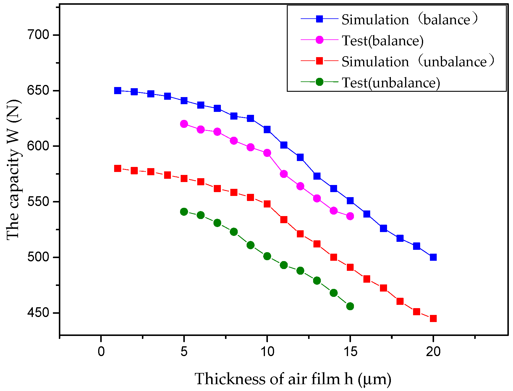
4.2. Results and Analysis

The total load bearing capacities of the aerostatic guideway were tested on the air film in both balanced and unbalanced conditions, and the related curves obtained from simulations and tests are shown in Figure 17. As the upper air film thickness increases, the values of the bearing capacity of the air film by both simulations and experiments decrease, in spite of either the balanced or unbalanced states. The experimentally extracted values are slightly lower than the simulated results, while their variation trend is consistent. The deviation is expressed as the ratio of the difference between the simulated and actual quantities to the simulated one, which is used to evaluate the test results. The average value of deviation is 3.59 percent in the air film in the balanced condition, while the average value of deviation reaches 6.61 percent in the air film in the unbalanced condition.
In addition, the simulation analyses are performed under absolutely idealized conditions. However, in the experimental process, there existed manufacturing errors in the test platform. Moreover, the solid material parameters set in the models also differ from the actual conditions. In addition, the experimental environment has an impact on the experimental results. The above factors led to the discrepancies between the experimental and simulation results of the bearing capacity of the aerostatic guideway.

5. Conclusions

In this paper, a cableless aerostatic guideway is proposed and the relevant fluid properties are analyzed to verify the feasibility of the proposed structure. Since the structural properties of a cableless guideway lead to an unbalanced state of the gas film, the Reynolds equation is modified by considering the velocity slip and thinning effects on the micro-scale and the flow boundary conditions of the fluid. With the air film in symmetric balance and the ultimate unbalance as the research objects, the variation of air film pressure and velocity vector are analyzed. Under the same conditions, compared with the balanced condition, the average pressure of the air film in an unbalanced condition is lower, the stiffness is higher, and the flow velocity at throttle orifices is higher with no significant vortices. Moreover, the outlet pressure at the partially covered throttle hole is slightly higher than the other boundaries, which leads to a slight offset in the pressure on the surface of an unbalanced air film. At any certain supply pressure, the bearing capacity of the guideway decreases with the increasing thickness of the air film, while the stiffness tends to first increase and then decrease later on. Besides, the trends of tests results and simulation results are consistent.
This study shows that the aerostatic guideways can work and be relatively stable in both extreme states, thereby enabling the application of cableless aerostatic guideways in the ultra-precision field. It provides a good foundation for improving the dynamic performance of cableless guideways in the future.

Author Contributions

Conceptualization, Y.Z. and W.Z.; methodology, T.S.; software, Y.Z.; validation, Z.H. and X.Z.; writing—original draft preparation, Y.Z.; writing—review and editing, W.Z. and J.Z.; supervision, T.S. All authors have read and agreed to the published version of the manuscript.

Funding

This research was funded by THE SCIENCE CHALLENGE PROJECT OF CHINA, grant number TZ2018006-0202-02.

Institutional Review Board Statement

Not applicable.

Informed Consent Statement

Not applicable.

Data Availability Statement

Not applicable.

Acknowledgments

The authors thank the comments and suggestions of reviewers.

Conflicts of Interest

The authors declare no conflict of interest.

References

  1. Shinno, H.; Hashizume, H.; Yoshioka, H.; Komatsu, K.; Shinshi, T.; Sato, K. X-Y-θ Nano-Positioning Table System for a Mother Machine. CIRP Ann.-Manuf. Technol. 2004, 53, 337–340. [Google Scholar] [CrossRef]
  2. Akhondzadeh, M.; Vahdati, M. Study of variable depth air pockets on air spindle vibrations in ultra-precision machine tools. Int. J. Adv. Manuf. Technol. 2014, 73, 681–686. [Google Scholar] [CrossRef]
  3. Chen, G.D.; Sun, Y.Z.; Zhang, F.H.; Lu, L.H.; Chen, W.Q.; Yu, N. Dynamic Accuracy Design Method of Ultra-precision Machine Tool. Chin. J. Mech. Eng. 2018, 31, 8. [Google Scholar] [CrossRef] [Green Version]
  4. Leach, R.K.; Flack, D.R.; Hughes, E.B.; Jones, C.W. Development of a new traceable areal surface texture measuring instrument. Wear 2009, 266, 552–554. [Google Scholar] [CrossRef]
  5. Marsh, E.; Schalcosky, D.; Couey, J.; Vallance, R. Analysis and performance of a parallel axis flatness measuring instrument. Rev. Sci. Instrum. 2006, 77, 2693. [Google Scholar] [CrossRef] [Green Version]
  6. Bos, E.; Moers, T.; Van Riel, M. Design and verification of an ultra-precision 3D-coordinate measuring machine with parallel drives. Meas. Sci. Technol. 2015, 26, 085904. [Google Scholar] [CrossRef]
  7. Chen, G.; Ju, B.; Fang, H.; Chen, Y.; Yu, N.; Wan, Y. Air bearing: Academic insights and trend analysis. Int. J. Adv. Manuf. Technol. 2020, 106, 1191–1202. [Google Scholar] [CrossRef]
  8. Zhou, Y.; Zong, W.; Tan, Q.; Hu, Z.; Sun, T.; Li, L. End Effect Analysis of a Slot-Less Long-Stator Permanent Magnet Linear Synchronous Motor. Symmetry 2021, 13, 1939. [Google Scholar] [CrossRef]
  9. Belforte, G.; Raparelli, T.; Trivella, A.; Viktorov, V.; Visconte, C. CFD Analysis of a Simple Orifice-Type Feeding System for Aerostatic Bearings. Tribol. Lett. 2015, 58. [Google Scholar] [CrossRef] [Green Version]
  10. Zhang, J.; Zou, D.; Ta, N.; Rao, Z. Numerical research of pressure depression in aerostatic thrust bearing with inherent orifice. Tribol. Int. 2018, 123, 385–396. [Google Scholar] [CrossRef]
  11. Miyatake, M.; Yoshimoto, S. Numerical investigation of static and dynamic characteristics of aerostatic thrust bearings with small feed holes. Tribol. Int. 2010, 43, 1353–1359. [Google Scholar] [CrossRef]
  12. Charki, A.; Diop, K.; Champmartin, S.; Ambari, A. Numerical simulation and experimental study of thrust air bearings with multiple orifices. Int. J. Mech. Sci. 2013, 72, 28–38. [Google Scholar] [CrossRef] [Green Version]
  13. Eleshaky, M.E. CFD investigation of pressure depressions in aerostatic circular thrust bearings. Tribol. Int. 2009, 42, 1108–1117. [Google Scholar] [CrossRef]
  14. Chen, D.; Huo, C.; Cui, X.; Pan, R.; Fan, J.; An, C. Investigation the gas film in micro scale induced error on the performance of the aerostatic spindle in ultra-precision machining. Mech. Syst. Signal Process. 2018, 105, 488–501. [Google Scholar] [CrossRef]
  15. Chen, D.; Dong, L.; Pan, R.; Fan, J.; Cheng, Q. Coupling effects of the impact factors in micro-scale on the performance of aerostatic guideway. Ind. Lubr. Tribol. 2018, 70, 846–855. [Google Scholar] [CrossRef]
  16. Li, Y.; Han, D. Influences of the geometrical parameters of aerostatic thrust bearing with pocketed orifice -type restrictor on its performance. Tribol. Int. 2007, 40, 1120–1126. [Google Scholar] [CrossRef]
  17. Gao, S.; Cheng, K.; Chen, S.; Ding, H.; Fu, H. CFD based investigation on influence of orifice chamber shapes for the design of aerostatic thrust bearings at ultra-high speed spindles. Tribol. Int. 2015, 92, 211–221. [Google Scholar] [CrossRef]
  18. Chen, Y.S.; CCChiu Cheng, Y.D. Influences of operational conditions and geometric parameters on the stiffness of aerostatic journal bearings. Precis. Eng. 2010, 34, 722–734. [Google Scholar] [CrossRef]
  19. Cui, H.L.; Wang, Y.; Wang, B.R.; Yang, H.; Xia, H. Numerical Simulation and Experimental Verification of the Stiffness and Stability of Thrust Pad Aerostatic Bearings. Chin. J. Mech. Eng. 2018, 31, 23. [Google Scholar] [CrossRef] [Green Version]
  20. Belforte, G.; Colombo, F.; Raparelli, T.; Trivella, A.; Viktorov, V. Comparison between grooved and plane aerostatic thrust bearings: Static performance. Meccanica 2010, 46, 547–555. [Google Scholar] [CrossRef] [Green Version]
  21. Shi, B.J.; Yang, T.Y. Simplified model of Reynolds equation with linearized flow rate for ultra-thin gas film lubrication in hard disk drives. Microsyst. Technol. 2010, 16, 1727–1734. [Google Scholar] [CrossRef]
Figure 1. Structure and principle of the cableless aerostatic guideway: (a) overall structure of the aerostatic guideway; and (b) operating principle of aerostatic guideway: 1—air compressor, 2—air dryers, 3—gas tank, 4—flow control valve, and 5—filter.
Machines 10 00308 g001
Figure 2. The (a) balanced and (b) unbalanced air film structure of the cableless aerostatic guideway.
Machines 10 00308 g002
Figure 3. Configuration of the throttle orifice with the slider.
Machines 10 00308 g003
Figure 4. Flow chart of the calculation of governing equation.
Machines 10 00308 g004
Figure 5. The CFD models with (a) balanced and (b) unbalanced air films.
Machines 10 00308 g005
Figure 6. Dimensional parameters of air film.
Machines 10 00308 g006
Figure 7. (a) Pressure distribution on a balanced surface of an air film (0.5 MPa). (b) Pressure distribution near the throttle hole.
Machines 10 00308 g007
Figure 8. (a) Pressure distribution on an unbalanced surface of an air film (0.5 MPa). (b) Pressure distribution near the half-covered throttle hole. (c) Pressure distribution near the fully covered throttle hole.
Machines 10 00308 g008
Figure 9. The velocity vector distribution of an air film in a balanced state (0.5 MPa). (a) Global view. (b) The position near a throttle hole. (c) The YOZ section of the air film (the highlighted line of the global view).
Machines 10 00308 g009
Figure 10. The velocity vector distributions of air films in unbalanced states (0.5 MPa). (a) Global view. (b) The position near the half-covered throttle hole. (c) The position near the fully covered throttle hole. (d) The YOZ section of the air film (the highlighted line of the global view).
Machines 10 00308 g010
Figure 11. Effect of the supply pressure on the surface pressure of an air film in a balanced state.
Machines 10 00308 g011
Figure 12. Effect of the supply pressure on the surface pressure of an air film in an unbalanced state.
Machines 10 00308 g012
Figure 13. Variation curves of the bearing capacity with the thickness of air films.
Machines 10 00308 g013
Figure 14. Variation curves of the static stiffness with the thickness of air films.
Machines 10 00308 g014
Figure 15. Schematic diagram for the bearing capacity measurement experiment. (a) The bearing capacity changes the thickness of an air film; and (b) the method for determining the thickness of an air film.
Machines 10 00308 g015
Figure 16. The realized experimental equipment of the cableless aerostatic guideway.
Machines 10 00308 g016
Figure 17. The variations of bearing capacities with the thickness of air films by the simulations and experiments.
Machines 10 00308 g017
Table 1. Structural parameters of the model.
Aerostatic GuidewayDesigned Value
The length of air film L280 mm
The breadth of air film HC66 mm
The breadth of air film HA56 mm
The breadth of air film HB61 mm
The distance from the edge of air film to the nearby orifice L140 mm
The distance between orifices L250 mm
The diameter of air cavity d24 mm
The height of air cavity h25 mm
The average thickness of air film h10 μm
The diameter of orifice d10.1 mm
The height of orifice h10.5 mm
Publisher’s Note: MDPI stays neutral with regard to jurisdictional claims in published maps and institutional affiliations.

