Abstract
Optimizing electromagnetic performance and vibration noise performance simultaneously is important when designing the drive motor for electric vehicles (EVs). This has not been fully explored, and there are only a few relevant studies. To achieve simultaneous optimization, this paper proposes an equivalent structural network (ESN) of stator assembly to calculate the modal distribution and harmonic response transfer functions. Based on the ESN model, the motor’s electromagnetic vibration noise harmonic response, such as acceleration and equivalent radiated power level (ERPL), can be quickly calculated. The feasibility of the established ESN model is verified by structural-field finite-element method (FEM) and modal hammer tests. Based on the modern optimization algorithm and the ESN model, an improved multi-physics and multi-objective optimization design approach is proposed for an optimized design of a 30 kW interior permanent-magnet synchronous machine (IPMSM). The motor’s maximum output torque and ERPL were selected as optimization objectives, and then the ERPL and acceleration were recalculated using structural-field FEM to validate the accuracy of the optimal design. Finally, vibration acceleration tests were carried out on a manufactured prototype motor to verify the feasibility and validity of the proposed optimization design method.
1. Introduction
In recent years, with the worsening of the energy crisis and environmental pollution, electric vehicles (EVs) have become an emerging focus in worldwide research [1,2,3] due to their advanced merits of emitting zero pollution, high efficiency, and energy-saving qualities. The drive motor is one of the key components in EVs, which directly affects dynamic performance and comfort. However, the problems of the high-frequency electromagnetic vibration and noise in drive motors have emerged during the vigorous pursuit of higher power density and speed [4,5].
To solve the problems mentioned above, scholars have proposed different theoretical analysis methods [6,7] and experimental methods [8,9] to improve the performance of drive motors. With the improvement of computing performance, the multi-physical field-coupling numerical calculation method [10,11,12,13] is becoming mainstream compared to traditional analysis methods, and is considered to be an effective way to analyze electromagnetic vibration and noise.
Having considered the additional mass and stiffness of windings and the orthotropic properties of the laminates, McCloskey [6] proposed an improved analytical model for calculating motor vibrations. Torregrossa quickly calculated the electromagnetic vibration of IPMSM based on the field reconstruction method [7] and mechanical impulse response function, in which the field reconstruction method calculated the electromagnetic-force value of the tooth under the corresponding current. In addition, the impulse response function obtained by simulation was used to calculate the vibration response of the tooth subjected to the electromagnetic force. This method can quickly obtain the electromagnetic vibration response of the motor under different excitations and states, such as rotor eccentricity and the partial demagnetization of permanent magnets.
However, the damping ratio of the stator assembly and the stiffness of the connection between components are difficult to calculate accurately. Therefore, the experimental method and FEM are the alternative choices to obtain the motor vibration transfer function. To quickly diagnose abnormal noise sources and corresponding working conditions of hub permanent-magnet synchronous motors, a novel black- and white-box method is presented in [9]. The black box method used experiments to diagnose abnormal noises.
A multi-physical coupling model has been developed to investigate the effect of teeth order forces on vibration and noise [10]. During the analysis, a 2D electromagnetic FEM was built to calculate the electromagnetic radial force on the stator teeth. Radial concentrated forces were applied to the stator teeth of a 3D structural FEM. The modal superposition method is applied for the calculation of deformation and vibration. In addition, vibration also verifies that the slot number order radial force is the root of the 0th-mode vibration of the integral slot motor. Zuo [11,12,13] also used this method to calculate the influence of the current harmonic introduced by the controller and the change in speed on the vibration and noise of the motor.
Additionally, Saito [14] proposed an empirical vibration synthesis method for motors, combining experimentation and simulation. The method used electromagnetic FEM to calculate the electromagnetic force on the stator teeth, obtained the transfer function of the stator assembly by the experimental method, and obtained the acceleration response of the motor by the mode superposition method and discrete Fourier transformation (DFT) method. This method accurately obtained the vibration spectrum of the motor at different speeds, which is convenient for identifying the contribution of each spatial and temporal order of the electromagnetic force to the system assembly vibration. Fang [15] investigated the effects of tooth modulation and tangential electromagnetic force on the vibration and noise of a 12-slot 10-pole motor using a hybrid computational model. Similarly, the proposed hybrid model uses FEM to obtain the modal shape function of the stator assembly and uses the experimental method to obtain the amplitude response function of the vibration, and finally obtains the vibration transfer function.
Most existing literature is focused more on the calculation and analysis of electromagnetic vibration and noise performance after the motor design has been completed [16,17]. However, the vibration and noise problem of the motor should be considered to be a design specification, and objects should be optimized at the design stage. Meanwhile, compared with the 2D electromagnetic-field FEM, the establishment and calculation of the vibration and noise harmonic response model of the 3D structural FEM consumes a lot of computational time and cost. This makes it unrealistic to use the 3D structural FEM to iteratively calculate and optimize the vibration and noise performance of the motor during the design stage.
In this paper, a novel rapid calculation method of electromagnetic vibration and noise and a multi-physics, multi-objective optimization design approach to drive motors based on electromagnetic FEM and ESN is proposed. The proposed method can be summarized as follows. The response function of vibration acceleration and velocity of the motor surface to air-gap harmonic electromagnetic force is first obtained by ESN, and the air-gap electromagnetic force is obtained through 2D electromagnetic FEM and the Maxwell stress tensor equation. Then, the electromagnetic vibration ERP and sound pressure level of the stator surface of the motor under different working conditions and speeds can be quickly obtained. Finally, combined with the improved particle swarm optimization algorithm, the electromagnetic performance and vibration and noise performance of the motor can be optimized simultaneously. The proposed method was verified on a 30 kW IPMSM used for EVs, while modal hammer tests and acceleration experiments were also used to verify its accuracy.
The paper is organized as follows. In Section 2, the mathematical ESN of stator assembly is given. In Section 3, combined with ESN and electromagnetic FEM, the rapid calculation method of vibration and noise performance of IPMSM is given. In Section 4, a multi-physics and multi-objective optimization design method for the IPMSM, considering the maximum output torque and the ERP of the motor surface, is proposed. In Section 5, experiments are performed on a prototype to verify the feasibility of the fast calculation method and optimization method. Finally, concluding remarks are presented in Section 6.
2. Equivalent Structural Network
As mentioned above, it is not practical to calculate the vibration transfer function using a 3D structural-field FEM during the motor’s iterative design due to computational time and cost. Therefore, it is necessary to propose a calculation method for electromagnetic vibration and noise with high accuracy in a short time. Here, a novel equivalent triple-cylinder structure network for stator assembly is proposed for the calculation of the structural transfer function of stator assembly quickly and accurately.
2.1. Analytical Model of the Cylindrical Shell and ESN
The stator assembly consists of three parts: the shell, stator core, and armature winding, which is embedded in the teeth of the stator core. Therefore, the stator teeth, where the windings are installed, the stator yoke and the shell are the equivalent of three rigidly connected cylinders, as shown in Figure 1.
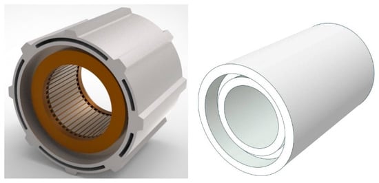
Figure 1.
Stator assembly structure and equivalent triple-circular cylindrical shell.
As shown in Figure 2a, the mechanism of high-frequency electromagnetic vibration of the stator assembly is as follows. The radial and tangential components of the magnetic density in the air gap of the motor interact with each other, which not only generates a tangential force density that produces torque, but also generates radial harmonic electromagnetic force. These radial electromagnetic forces of various spatial orders and temporal frequencies act on the stator teeth, which cause the teeth to vibrate forcibly. The stator yoke and the casing, which are rigidly connected to the stator teeth, will also vibrate accordingly. When the spatial order and temporal frequency of the radial electromagnetic force are close to one natural mode of the stator assembly, resonance will occur. In the whole vibrating system, the armature winding is embedded in the stator core, which can be regarded as a flexible connection without considering the glue filling. In this case, winding can be regarded as an additional mass to the stator core [18].
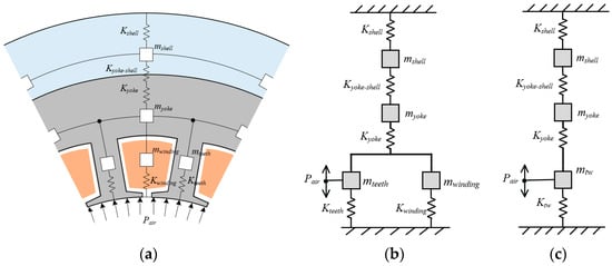
Figure 2.
Schematic diagram of stator assembly vibration and equivalent ESN model: (a) schematic diagram of stator assembly vibration; (b) ESN model of an IPMSM stator assembly; (c) simplified ESN model.
Because the radial air-gap force of the motor is symmetrically distributed on the circumference, the electromagnetic vibration of the motor is mainly circumferential.
According to the vibration mechanism and the construction method of the motor reluctance network, the ESN of the motor stator assembly can be obtained, as shown in Figure 2b. Ktw, Kyoke, and Kshell are the stiffnesses of the stator teeth (including the windings), stator yoke and shell, respectively. In addition, mtw, myoke, and mshell are the masses of the stator teeth (including the windings), stator yoke and shell, respectively. Pair is the radial electromagnetic force of the air gap. Kyoke-shell is the connection stiffness between the stator yoke and the shell. When there is no relative tangential displacement between the stator core and the shell, the connection stiffness Kyoke-shell is equivalent to infinity, which can be ignored.
For a cylinder with an equivalent radius of Rc and a thickness of hc, the stiffness corresponding to the n-order circumferential vibration mode is given in [7,9] as follows:
where Lc is the axial length of the cylinder; Ec and Vc are the equivalent Young’s modulus and Poisson’s ratio of the cylinder; and Ωn are the roots of second order characteristic equation of motor.
For circumferential vibration mode n = 0 (breathing vibration)
For circumferential vibration mode n ≥ 1
where κ is the nondimensional thickness parameter:
The mass of the cylinder is:
where ρc is the equivalent density of the cylinder. In this method, the stiffness and mass of each cylinder of the stator assembly can be obtained. According to [6,18] and the ESN model, the triple-circular cylinder is assembled similar to a lumped parameter model, so that the equivalent mass and stiffness of both cylinders are added. Therefore, the total stiffness and total mass of the stator assembly are:
The natural frequency of the n-order circumferential vibration mode of stator assembly is:
After obtaining the stiffness and mass of each vibration order of the stator assembly, the differential equation of motion of the stator assembly under the radial air-gap electromagnetic-force Pair is:
where cn and ξn are the damping and damping ratio of the system, respectively, and Y is the vibration response displacement. The response velocity of the forced vibration of the stator is obtained by solving (8):
Solving (10), the response velocity transfer function amplitude and acceleration transfer = function amplitude of the stator assembly to the n-order air-gap radial electromagnetic force of the motor can be obtained:
where Pair is the radial electromagnetic force, vn is velocity amplitude, an is acceleration velocity amplitude, and f is electric frequency of the radial electromagnetic force Pair. According to [19], the equivalent radiated power (ERP) and equivalent radiated power level (ERPL) of the stator assembly surface are:
where c is the speed of sound (343.25 m/s), ρ0 is the air mass density (1.2041 kg/m3), σ is the radiation factor (≈1), and Wref is the reference sound power (10−12 W).
2.2. Structural Transfer Function of a 30 kW IPMSM and FEM Verification
The ESN model using a method to calculate the structural transfer function of the motor is described above. In this section, a 30 kW IPMSM is used as an example to calculate specific structural transfer functions for different orders of circumferential vibration modes. The structural parameters of the stator are shown in Figure 3 and Table 1.
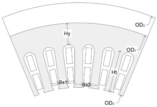
Figure 3.
The structure size parameters of stator assembly.

Table 1.
Structural parameters of stator assembly.
The material properties of each component of the motor are shown in Table 2. It is worth mentioning that the stator teeth and armature windings are equivalent to a cylinder, and their equivalent structural parameter properties conform to Voigt or Reuss mixing rules. For the axial Young’s modulus, teeth and windings work in parallel, as follows [20]:
Table 2.
Mechanical properties of materials.
For the radial and tangential Young’s modulus, stator teeth and windings work in series, as follows:
where φteeth, φwinding are the volume fractions of stator teeth and windings, and Eteeth, Ewinding are the Young’s modulus of stator teeth and windings (equivalent).
By substituting the motor size parameters shown in Table 1 into Equations (1)–(12), the transfer function of this 30 kW stator assembly can be obtained. It should be noted here that the damping ratio of the motor is obtained by experimental methods and empirical coefficients. Figure 4 shows the velocity and ERPL transfer function curve of each circumferential order mode to the air-gap electromagnetic unit force calculated by the ESN model. It can be found that with the increase of the spatial order, the corresponding natural frequency increases, while the velocity and ERPL amplitude, when the stator assembly resonates, gradually decreases. Therefore, in the electromagnetic vibration and noise analysis of the motor, the high-spatial-order air-gap electromagnetic force often does not need to be considered [8]. Meanwhile, an accurate structural-field FEM of the stator assembly was established, and the structural transfer function of each spatial order was also calculated to verify the accuracy of the ESN model, as shown in Figure 4. It can be seen that the calculation results of the ESN model are in good agreement with the FEM results, which verifies the accuracy of the ESN model.
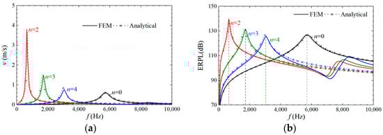
Figure 4.
Structural transfer function to air-gap electromagnetic unit force: (a) velocity transfer function; (b) ERPL transfer function.
2.3. Modal Hammering Test
The modal hammer test can also be used to verify the accuracy of the ESN model. The test arrangement is shown in Figure 5a. The prototype was suspended by a flexible wire to simulate the free boundaries as much as possible, to compare with the ESN and FEM results. In addition, 72 measurement points were arranged evenly on the outer surface of the stator assembly. A hammer is used to excite the free vibration of the stator assembly under test. Figure 5b shows the modal shape of each mode. Table 3 also gives the frequency values and errors of each modal order that were obtained by the test, ESN and FEM methods. The maximum error of the proposed ESN model is lower than 7%, which demonstrates that the ESN model is accurate and can be used to calculate the electromagnetic vibration and noise of the motor.
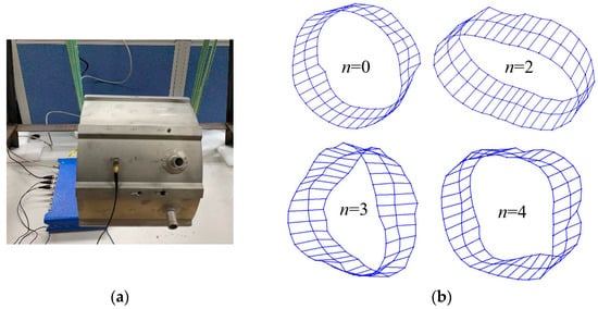
Figure 5.
Modal hammering test of the stator with winding and shell: (a) stator assembly and test photos; (b) tested shape of each mode.
Table 3.
Comparison of the modal frequencies from ESN, FEM and modal hammering test.
3. Electromagnetic Vibration and Noise Rapid Calculation Based on ESN
In this section, the rapid calculation of electromagnetic vibration and noise based on ESN is used to quickly calculate the vibration and noise harmonic response distribution of a 30 kW IPMSM for EVs under different speed conditions, and the accuracy of the method is verified by the structural-field FEM.
3.1. Rapid Calculation Process
A flow chart of the rapid calculation method of electromagnetic vibration and noise of IPMSM is shown in Figure 6. The method observed here includes six steps, as follows:
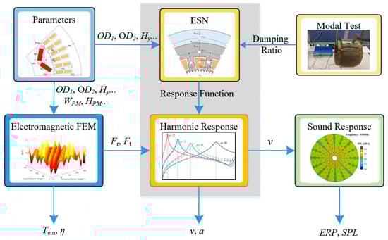
Figure 6.
Flow chart of rapid calculation method for electromagnetic vibration and noise.
Step 1: Establish the IPMSM parametric model and define the size of the structural parameters. Then, transfer the stator structure parameters to the electromagnetic-field FEM and transfer the stator and the shell structure parameters to the ESN model.
Step 2: Establish the 2D electromagnetic-field FEM of IPMSM and calculate the electromagnetic performance of the motor such as motor torque, efficiency, etc. Calculate the motor radial electromagnetic force (under different conditions) according to the Maxwell stress tensor equation and transfer it to the harmonic response calculation.
It is noted that, differently from the structural-field FEM model, the 2D electromagnetic-field FEM can quickly calculate the electromagnetic performance and magnetic field distribution of the motor with high accuracy.
Step 3: Obtain the ESN model and motor structure transfer function according to Section 2.
Step 4: Obtain the stator assembly damping ratio. The stator assembly damping ratio value is closely related to the installation method and material, so it is difficult to obtain accurate values through an analytical method. In the iterative design of the motor, the stator size changes over a small range. Therefore, if the damping ratio of the stator assembly does not change, the damping ratio of the stator assembly can be corrected through one modal test. In addition to the modal test, empirical values can be used instead.
Step 5: Obtain the motor vibration velocity and acceleration according to the electromagnetic-force harmonic in Step 2, the transfer function in Step 3, and the mode superposition method.
Step 6: Obtain the equivalent radiated power (ERP) and sound pressure level (SPL) of the motor surface according to the vibration velocity of the shell surface in Step 5.
The following will take a 30 kW IPMSM for EVs as an example to verify the feasibility of the above rapid calculation method. The main performance requirements of the 30kW IPMSM are shown in Table 4. The structural parameters of the stator assembly are shown in Table 1.
Table 4.
Main parameters of 30 kW IPMSM.
3.2. Air-Gap Electromagnetic-Force Calculation by Electromagnetic-Field FEM
By establishing the 2D electromagnetic-field FEM of IPMSM, the electromagnetic force on the stator teeth was calculated, as shown in Figure 7.
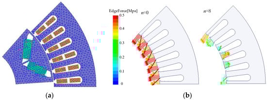
Figure 7.
Two-dimensional electromagnetic FEM of IPMSM and electromagnetic-force distribution: (a) meshing of motor model; (b) distribution of radial electromagnetic force (n = 0 and n = 8).
The performance of 2D Fourier decomposition on the air-gap flux density and radial electromagnetic force of the motor under rated operating conditions to obtain its harmonic distribution in temporal and spatial order is shown in Figure 8. It shows that for the integer-slot motor, in addition to the 0th-order spatial radial-force harmonic, the air-gap radial electromagnetic force has only a 2mp orders spatial harmonic (m = 1, 2, …, p is pole pairs). However, according to the above and [21], it is difficult for the radial harmonic electromagnetic force of high spatial order to have a large vibration response that can be ignored. Therefore, in the integer-slot IPMSM, only the 0th-order spatial radial electromagnetic harmonic force is considered, which simplifies the calculation process.

Figure 8.
The air-gap flux density distribution and radial electromagnetic force under rated condition: (a) air-gap flux density and 2D-FFT; (b) air-gap radial electromagnetic force and 2D-FFT.
3.3. Acceleration and ERPL Calculation by ESN and Modal Superposition Method
The ESN model has been established in Section 2 and will not be repeated here. According to Step 5, the corresponding acceleration and ERPL values of the motor under different speed conditions are obtained. An accurate structural-field FEM of the stator assembly was established, and the acceleration and ERPL under different speeds were also calculated, as shown in Figure 9. Meanwhile, the spectral waterfall diagram of ERPL calculated by the proposed method (2 min) and the structural-field FEM (307 min) is also shown in Figure 10. It can be seen that for integer-slot IPMSM, the vibration of the motor is mainly caused by the 0th-order spatial mode. When the frequency of tooth harmonic force is close to the natural frequency of the 0th-order spatial mode, resonance occurs (breathing vibration) such that the surface-radiated sound power of the motor increases. In practical motor design, the method of avoiding the natural frequency of the 0th-order spatial mode or reducing the magnetic teeth harmonic is often used to reduce 0th-order vibration.
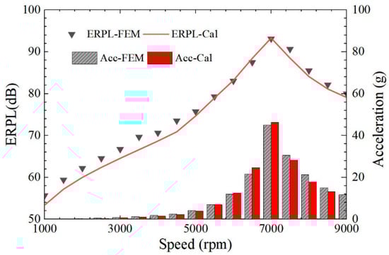
Figure 9.
ERPL and acceleration of the motor under different speed conditions by ESN and FEM.
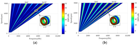
Figure 10.
ERPL spectral waterfall diagram under different speed conditions by ESN and FEN: (a) ESN; (b) structural-field FEM.
It can be seen from Figure 9 that the ERPL and acceleration results using the proposed ESN model agree with the FEM results, which verifies the accuracy of the ESN model. However, the ERPL spectrum calculated by the two methods is slightly different in Figure 10. The main reasons for the error are, first, to speed up the calculation and, according to previous research, the spatial electromagnetic-force harmonics of spatial order n > 4 are not considered in the proposed method. Second, the influence of the tangential electromagnetic force is not considered while the low-order tangential force will cause the tangential teeth to swing, and then cause radial vibration of the stator assembly. In fact, the amplitude of electromagnetic vibration noise generated by these factors is relatively small and does not affect the large change in the synthetic vibration noise, as shown in Figure 9.
4. Optimization of Electromagnetic Vibration Noise
With the rapid calculation method proposed in this paper, the multi-physics and multi-objective optimization of the electromagnetic and vibration noise performance of the drive motor becomes feasible. The same 30 kW IPMSM is taken as an example, and its vibration and noise performance and electromagnetic performance are optimized in this section.
4.1. Optimization Flow
Figure 11 shows the flow chart of the optimized design method for the multi-objective (electromagnetic and vibration noise performance), multi-physics-field (electro-magnetic-structure-harmonic response coupling field) for the IPMSM, which includes three steps:
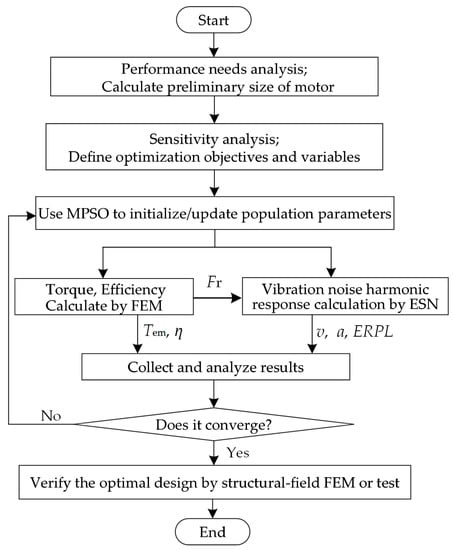
Figure 11.
Optimization design flow.
Step 1: Carry out the preliminary electromagnetic theoretical design of IPMSM for EVs. Analyze the design requirements and design objectives, use theoretical formulas and design experience to calculate the initial size of the motor. In addition, use sensitivity analysis to define the optimization variables.
To better express the optimization objectives, in this paper the electromagnetic output torque and the maximum ERPL of the motor are used. In addition, electromagnetic efficiency, loss, vibration acceleration, and SPL can also be selected as optimization objectives. The optimization methods are the same and will not be described here. The optimization variables are the structural parameters of the motor.
Step 2: Iteratively calculate and optimize the electromagnetic output torque and the motor ERPL vibration simultaneously.
In this step, the modified particle swarm optimization (MPSO) in our previous research [22] can be used to initialize and update the particle swarm population parameters. In the iterative process, the electromagnetic-field FEM is used to calculate peak output torque under different parameters, as well as the radial electromagnetic-force distribution of the air gap. At the same time, the vibration harmonic response is calculated using the proposed ESN according to Section 2. Then, the maximum vibration acceleration, ERPL, is obtained by the modal superposition method and the obtained electromagnetic-force distribution. The MPSO is used for iterative optimization until the design scheme converges.
Step 3: Compare the optimal design results before and after optimization, and verify the accuracy using structural-field FEM.
4.2. Sensitivity Analysis
From the above, the optimal design process of IPMSM used for EVs can be regarded as a multi-objective and multi-physics field problem. The significance of sensitivity analysis is to observe the influence of different variables on objectives, to guide the optimization process. The main purpose of sensitivity analysis is to analyze the influence of optimization variables and objectives, to eliminate or reduce the analysis scope of unnecessary variables, to guide optimization reversals and to reduce optimization time. At the same time, sensitivity analysis can also be used to observe the most important influencing variables of the optimization objectives.
In this section, the analysis objectives are the output torque Tavg, the torque ripple Tpkavg, the amplitude of the tooth harmonic radial electromagnetic-force F0p12f of the key order (0th spatial order with 12th temporal times), and the maximum vibration ERPLmax caused by the air-gap radial unit force. The analysis variables are the stator slot opening width Bs0, stator outer diameter Dout, permanent-magnet width WPM, stator slot-tooth width ratio α, stator tooth-yoke thickness ratio β, and ratio of inner and outer diameter of stator γ.
Therefore, based on (15), the sensitivity index of each variable on the objectives can be calculated, as shown in Figure 12. It can be seen that the output torque of the motor is mainly determined by stator slot-tooth width ratio α, ratio of inner and outer diameter of stator γ and the size of the permanent magnet. However, the torque ripple of the motor is mainly influenced by the width of the stator slot opening width Bs0 and stator slot-tooth width ratio α.
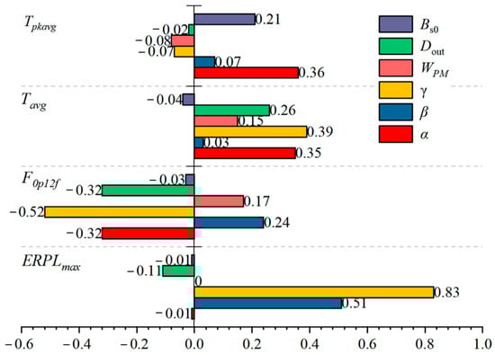
Figure 12.
Sensitivity analysis.
Meanwhile, the motor tooth harmonic radial electromagnetic-force F0p12f is mainly determined by stator slot-tooth width ratio α and the ratio of the inner and outer diameter of stator γ. The cogging effect of the motor changes dramatically as the stator teeth and slot widths change. The maximum vibration ERPLmax is mainly influenced by stator tooth-yoke thickness ratio β, and the ratio of the inner and outer diameter of stator γ. This is because when these two parameters increase, the stator yoke increases too. According to Equations (4)–(12), the damping of the stator assembly increases, therefore reducing the ERPL caused by the unit electromagnetic force.
4.3. Optimization Process and Results
Through the above method, the performance of the 30 kW IPMSM is optimized for multiple iterations. Its maximum ERPL and maximum output torque are optimized, as shown in Figure 13. It can be seen that in this figure, as the optimization progresses, the population gradually approaches the direction of high torque output and low ERPL, and finally converges to a certain position in one space, forming the Pareto front and optimal solution set. It can be seen that through iterative optimization, the output torque of the motor gradually increases, while the vibration ERPL value, from the original around 93 dB, is reduced to 85 dB at maximum. From the Pareto front we can select the optimal solution according to the torque requirement and electromagnetic vibration ERPL. It is important to know that ERPL is calculated logarithmically, so the value does not change much before and after optimization.
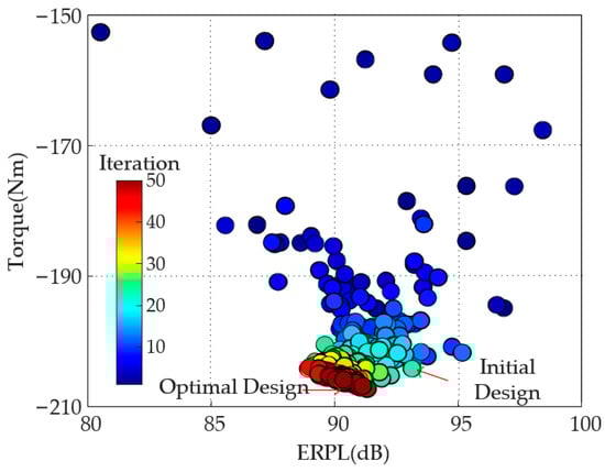
Figure 13.
Pareto Front and optimal solutions by 50 iterations.
After the optimization process proposed above, the vibration and noise performances of the motor, such as acceleration and ERPL, are improved. Figure 14 shows the comparison of the ERP and acceleration of the motor under different speed conditions before and after optimization. It can be seen that its vibration acceleration at 7000 rpm decreases from 46 g to 32 g and the noise ERPL is also decreased, from 93.3 dB to 90.2 dB, and the vibration noise performance of the motor improves by about 30%, which verifies the effectiveness of the proposed optimization design method.
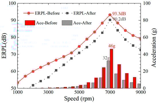
Figure 14.
ERPL and acceleration of the motor under different speed conditions before and after optimization.
5. Experimental Section
To verify the accuracy of the ESN model and the rapid calculation method of electromagnetic vibration and noise proposed in this paper, an IPMSM prototype was manufactured according to the aforementioned design scheme, as shown in Figure 15a. Meanwhile, an experimental bench was built to test the vibration acceleration of the motor surface under different speed conditions, as shown in Figure 15b.
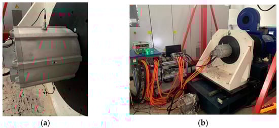
Figure 15.
Prototype and vibration acceleration test: (a) prototype with accelerometer. (b) test bench.
Figure 16 shows the comparative results by proposed ESN and prototype motor vibration acceleration test under different rotational speed conditions. It can be seen from the figure that the analytical results of the ESN in the high-speed section agrees with the test results. However, in the low speed range, the analytical results have a large error. This is mainly because the influence of the power supply controller is not considered in this paper. The tested motor is powered by an inverter, which will introduce a harmonic current close to the carrier frequency in the stator windings, therefore causing vibration close to the carrier frequency. In the following study, the influence of the harmonics introduced by the controller on the electromagnetic vibration and noise of the motor will be considered.
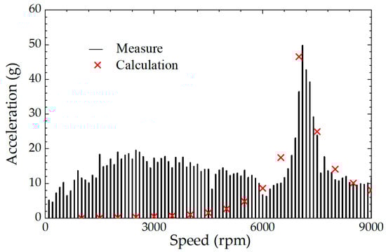
Figure 16.
Comparison of measured and analytical accelerations of the motor at different speeds.
Meanwhile, to verify the feasibility of the optimization design method in Section 4, prototypes were made according to the motor parameters before and after optimization, and vibration tests were carried out. Figure 17 shows the measured spectral waterfall diagrams of the motor vibration acceleration before and after optimization under different speed conditions. It can be seen that after optimization, the vibration amplitudes of the motor, especially the vibration caused by the electromagnetic force of the tooth harmonic component, have been significantly weakened, which verifies the feasibility of the optimal design method proposed in this paper.
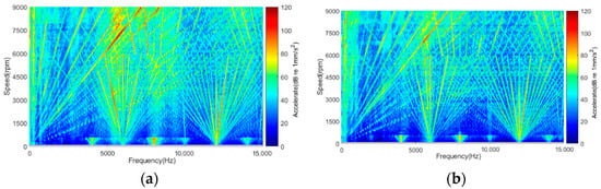
Figure 17.
Comparison of the acceleration spectrum waterfall before and after optimization: (a) before optimization; (b) after optimization.
6. Conclusions
This paper proposed an equivalent structural network (ESN) of stator assembly for the rapid calculation of the modal distribution and harmonic response transfer functions of electromagnetic vibration noise. Combining the ESN model and the modern optimization algorithm, the 30kW IPMSM vibration acceleration and noise equivalent radiation power levels for EVs were optimized. The accuracy and feasibility of the proposed optimization procedure was verified by prototype experiments. The main conclusions are as follows:
(1) As the spatial order increases, the motor vibration acceleration and velocity amplitude caused by unit radial force decreases. Therefore, the high-spatial-order air-gap radial electromagnetic force can be ignored to simplify the vibration harmonic response calculation process.
(2) In the integer-slot motors, such as the 8-pole 48-slot motors in this paper, in addition to the zeroth-order spatial electromagnetic force, the lowest-order spatial force is the eighth order. It can be seen from the above that it is difficult to cause large vibrations for the eighth-order spatial electromagnetic force. Therefore, in the integer-slot motor vibration and noise calculation, only considering the zeroth-order spatial electromagnetic-force harmonic response influence can obtain high calculation accuracy.
(3) The maximum vibration ERPLmax by unit radial force is mainly influenced by stator yoke thickness. As motor stator yoke thickness increases, stator assembly system damping increases and the vibration amplitude caused by unit radial force decreases. In engineering applications, stator yoke thickness can be appropriately increased to reduce electromagnetic vibration noise.
Author Contributions
Conceptualization, T.S. and Z.Z.; methodology, T.S.; validation, T.S. and B.B.; formal analysis, investigation, writing—original draft preparation, T.S.; data curation, T.S. and B.B.; writing—review and editing, T.S. and H.L.; visualization, T.S.; resources, supervision, project administration, H.L. All authors have read and agreed to the published version of the manuscript.
Funding
This research was funded by the Fundamental Research Funds for the Central Universities, Grant Number 2021YJS159.
Institutional Review Board Statement
Not applicable.
Informed Consent Statement
Not applicable.
Data Availability Statement
Not applicable.
Conflicts of Interest
The authors declare no conflict of interest.
References
- Husain, I.; Ozpineci, B.; Islam, M. Electric Drive Technology Trends, Challenges and Opportunities for Future Electric Vehicles. Proc. IEEE 2021, 109, 1039–1059. [Google Scholar] [CrossRef]
- Yang, W.; Fang, Z.; He, K. Analysis of Development and Application of In-Wheel Motor System for Electric Vehicle. Appl. Mech. Mater. 2015, 703, 409–412. [Google Scholar] [CrossRef]
- Ifedi, C.; Mecrow, B.; Brockway, S. Fault Tolerant In-Wheel Motor Topologies for High Performance Electric Vehicles. IEEE Trans. Ind. Appl. 2013, 49, 1249–1257. [Google Scholar] [CrossRef]
- Fang, Y.; Zhang, T. Sound Quality Investigation and Improvement of an Electric Powertrain for Electric Vehicles. IEEE Trans. Ind. Electron. 2018, 65, 1149–1157. [Google Scholar] [CrossRef]
- Yang, Z.; Shang, F.; Brown, I.; Krishnamurthy, M. Comparative Study of Interior Permanent Magnet, Induction, and Switched Reluctance Motor Drives for EV and HEV Applications. IEEE Trans. Transport. Electrif. 2015, 1, 245–254. [Google Scholar] [CrossRef]
- McCloskey, A.; Xabier, A.; Xabier, B. Analytical Calculation of Vibrations of Electromagnetic Origin in Electrical Machines. Mech. Syst. Signal. Process. 2018, 98, 557–569. [Google Scholar] [CrossRef]
- Torregrossa, D.; Fahimi, B.; Member, S. Fast Computation of Electromagnetic Vibrations in Electrical Machines via Field Reconstruction Method and Knowledge of Mechanical Impulse Response. IEEE Trans. Ind. Electron. 2012, 59, 839–847. [Google Scholar] [CrossRef]
- Fang, H.; Li, D.; Qu, R.; Yan, P. Modulation Effect of Slotted Structure on Vibration Response in Electrical Machines. IEEE Trans. Ind. Electron. 2019, 66, 2998–3007. [Google Scholar] [CrossRef]
- Ma, C.; Liu, Q.; Wang, D.; Li, Q.; Wang, L. A Novel Black and White Box Method for Diagnosis and Reduction of Abnormal Noise of Hub Permanent-Magnet Synchronous Motors for Electric Vehicles. IEEE Trans. Ind. Electron. 2016, 63, 1153–1167. [Google Scholar] [CrossRef]
- Wang, S.; Hong, J.; Sun, Y.; Cao, H. Analysis of Zeroth-Mode Slot Frequency Vibration of Integer Slot Permanent-Magnet Synchronous Motors. IEEE Trans. Ind. Electron. 2019, 67, 2954–2964. [Google Scholar] [CrossRef]
- Lin, F.; Zuo, S.; Deng, W.; Wu, S. Modeling and Analysis of Electromagnetic Force, Vibration, and Noise in Permanent-Magnet Synchronous Motor Considering Current Harmonics. IEEE Trans. Ind. Electron. 2016, 63, 7455–7466. [Google Scholar] [CrossRef]
- He, S.; Huang, Z.; Qin, R.; Chen, D. Numerical Prediction of Electromagnetic Vibration and Noise of Permanent-Magnet Direct Current Commutator Motors with Rotor Eccentricities and Glue Effects. IEEE Trans. Magn. 2012, 48, 1924–1931. [Google Scholar] [CrossRef]
- Lin, F.; Zuo, S.; Deng, W.; Wu, S. Noise Prediction and Sound Quality Analysis of Variable-Speed Permanent Magnet Synchronous Motor. IEEE Trans. Energy Convers. 2017, 32, 698–706. [Google Scholar] [CrossRef]
- Saito, A.; Kuroishi, M.; Nakai, H. Empirical Vibration Synthesis Method for Electric Machines by Transfer Functions and Electromagnetic Analysis. IEEE Trans. Energy Convers. 2016, 31, 1601–1609. [Google Scholar] [CrossRef]
- Fang, H.; Li, D.; Guo, J.; Xu, Y.; Qu, R. Hybrid Model for Electromagnetic Vibration Synthesis of Electrical Machines Considering Tooth Modulation and Tangential Effects. IEEE Trans. Ind. Electron. 2021, 68, 7284–7293. [Google Scholar] [CrossRef]
- Kawa, M.; Kiyota, K.; Furqani, J.; Chiba, A. Acoustic Noise Reduction of a High-Efficiency Switched Reluctance Motor for Hybrid Electric Vehicles with Novel Current Waveform. IEEE Trans. Ind. Appl. 2019, 55, 2519–2528. [Google Scholar] [CrossRef]
- Cho, S.; Hwang, J.; Kim, C. A Study on Vibration Characteristics of Brushless DC Motor by Electromagnetic-Structural Coupled Analysis Using Entire Finite Element Model. IEEE Trans. Energy Convers. 2019, 33, 1712–1718. [Google Scholar] [CrossRef]
- Gieras, J.; Wang, C.; Lai, J. Noise of Polyphase Electric Motors. Boca Raton; CRC Press: Boca Raton, FL, USA, 2018. [Google Scholar]
- Hu, S.; Zuo, S.; Wu, H.; Liu, M. An Analytical Method for Calculating the Natural Frequencies of a Motor Considering Orthotropic Material Parameters. IEEE Trans. Ind. Electron. 2019, 66, 7520–7528. [Google Scholar] [CrossRef]
- Chai, F.; Li, Y.; Pei, Y. Accurate Modelling and Modal Analysis of Stator System in Permanent Magnet Synchronous Motor with Concentrated Winding for Vibration Prediction. IET Electr. Power. Appl. 2018, 12, 1225–1232. [Google Scholar] [CrossRef]
- McDevitt, T.; Campbell, R.; Jenkins, D. An Investigation of Induction Motor Zeroth-Order Magnetic Stresses, Vibration, And Sound Radiation. IEEE Trans. Magn. 2004, 40, 774–7774. [Google Scholar] [CrossRef]
- Liu, H.; Song, T.; Du, J.; Liu, B. Optimization and Performance Comparison of Hairpin-Winding PMSM for Electric Vehicles Under Drive Cycle. Trans. Nanjing Univ. Aeronaut. Astronaut. 2021, 5, 713–724. [Google Scholar]
Publisher’s Note: MDPI stays neutral with regard to jurisdictional claims in published maps and institutional affiliations. |
© 2022 by the authors. Licensee MDPI, Basel, Switzerland. This article is an open access article distributed under the terms and conditions of the Creative Commons Attribution (CC BY) license (https://creativecommons.org/licenses/by/4.0/).