Abstract
Compared to the proportional-integral strategy, the repetitive control strategy possesses high suppression ability for the alternating current (AC) harmonics of control signals. Thus, RC controllers are widely used in closed-loop control systems to suppress the periodic harmonics. In order to further improve the brushless DC (BLDC) motor operation performance, a frequency adaptive repetitive controller (FARC) is proposed, and then a novel current loop scheme that concatenation of proportional-integral controller (PIC) and FARC controller is established in this paper. Firstly, due to the real sampling number of the delay element in the BLDC, the motor control system may not be an integer, the designing process of the FARC parameters was studied, and an adaptive internal model controller and a novel decomposition rule for FARC were designed based on Lagrange interpolation theory. Secondly, the PIC parameters were analyzed through three-dimensional and two-dimensional images of the frequency characteristics. Furthermore, a composite controller that added a forward channel in the novel current loop was proposed, and the stability of the control system used the composite controller was analyzed through Lyapunov theory. It should be noted that the analysis of FARC mainly focused on the simplified structure and the parameter optimization, which is usually ignored in the previous studies. Finally, the BLDC motor control system model was established through Matlab/Simulink software, and the operation performances of the BLDC motor control system utilizing different current loop controllers were studied. The simulation results show that the proposed FARC can reduce current distortion and torque ripples, thus, the BLDC motor operation performances can be improved effectively.
1. Introduction
The brushless DC (BLDC) motor control system is usually driven in six-step driving mode, and it features lots of merits, including simple control strategy and simple hardware configuration. Therefore, the BLDC motor control system is widely used in industrial equipment, robotics, and automotives [1,2]. However, the dead-zone time is inevitable during the working process of the inverter, which will introduce high amount harmonics to the stator current of the BLDC motor. Additionally, the non-ideal motor structure is also an essential factor that may affect the stator current distortion rate [3]. Hence, the output torque of the BLDC motor will be affected, leading to tracking errors in the coordination control of the industrial equipment [4]. In order to suppress torque ripple caused by the non-ideal current waveforms, the current loop controller needs the support of high-performance control strategies.
The PI control strategy can achieve no-static error tracking of the direct current (DC) signal. Thus, the PIC is commonly adopted in the current loop of the BLDC motor control system [5]. On the other hand, the PIC cannot achieve no-static error tracking of the alternating current (AC) signal, which means that the AC harmonics in the current loop cannot be suppressed [6,7]. Hence, the rotating synchronous-frame PIC is widely employed instead of the traditional PIC, which can provide the non-static error. However, the computational processes of the rotating synchronous frame are very tedious, which will increase the computational cost of the current loop [8,9,10,11]. In order to suppress the alternating-current harmonics and maintain the simplicity for the current loop, many researchers have attempted to optimize the current loop controller through resonant control theory and model predictive control theory [12,13,14,15,16]. Additionally, RC strategy and other control strategies are also used to simplify the complexity of the control system [17,18,19,20,21,22].
A novel, nonsingular terminal sliding mode scheme was adopted to guarantee the control system trajectory, which owns the finite-time stability. Additionally, the nonlinearities and the external disturbances of the control system were evaluated and suppressed by the finite-time exact observer, thus, the complexity of the control system could be simplified effectively. Finally, the stability of the closed-loop control system that composed of the observer and the sliding mode feedback controller was analyzed [23]. In order to address the control chattering caused by the sliding mode controller, a new pulse width modulation (PWM) model predictive control (MPC)method is proposed in [24]. The new PWM MPC method can avoid the commutation current hopping, and reduce the torque ripple through the changing of the duty cycle.
Additionally, to improve the PIC robustness to uncertain disturbances, an adaptive back electromotive force observer is proposed in [25]. The adaptive observer can obtain accurate back electromotive force without the using of sliding mode scheme and the low pass filter. Furthermore, the control chattering and the current harmonics can be suppressed by the quasi-proportional-resonant controller effectively. In [26], a novel fractional-order vector resonant (FOVR) robust internal mode controller (Robust-IMC) is proposed through combining FOVR controller and Robust-IMC, which can improve the current harmonics suppression ability. The resonant gain of the vector resonant controller can be maintained through the using of the FOVR controller. Additionally, the harmonics suppression performance can also be improved in the parameter mismatch condition.
In [27], the relationships between the quasi-resonant controller and the repetitive controller (RC) are analyzed, and a novel PI multi-resonant repetitive control (PI-MR-RC) method using modified RC the current loop is presented. The proposed PI-MR-RC scheme can improve the control stability and the harmonics suppression performance effectively.
The RC can provide excellent tracking performance for any periodic signal within a certain period, but the traditional RC cannot suppress the harmonics with a fractional period while the control frequency changed [28]. To solve the slow dynamic performance caused by the small RC gain of the traditional RC, a novel frequency adaptive proportional repetitive controller (FA-PRC) was proposed in [29]. The proposed FA-PRC owns a larger gain in comparison with traditional repetitive controller (TRC), thus the higher stability range of the RC gain is increased significantly.
Compared to PIC and traditional RC, the above proposed controllers can improve current harmonics suppression ability effectively. However, the complexity of the control system is inevitably increased. To further improve suppression performance of the alternating-current harmonics and maintain the simplicity of the control system, a FARC is proposed in in this paper, and a novel current loop scheme that concatenation of PIC and FARC is presented. Since the real sampling number of the RC may not be an integer, an adaptive internal model controller and a novel decomposition rule for FARC was studied. Hence, the anti-disturbance ability of the control system can be improved, meanwhile, the complexity of the control system can be simplified.
In order to suppress the harmonics in the BLDC motor control system, a novel composite current loop controller that concatenation of PIC and FARC is proposed in this paper. The major contributions of this paper are as follows:
- Due to the real sampling number of the delay element in the BLDC, the motor control system is maybe not an integer, the parameters designing process of FARC are studied, and an adaptive internal model controller and a novel decomposition rule for FARC is designed based on Lagrange interpolation theory;
- In order to simplify the control system scheme and obtain the appropriate parameters for the current loop controllers, the Bode diagrams and the Nyquist diagrams of different systems and controllers were analyzed, which can provide the intuitive analysis for the parameter designing process of the current loop;
- To improve the dynamic performance of the control system, a composite controller was proposed through adding a froward channel in the novel current loop. Consequently, the stability and robustness of the composite controller were verified by Lyapunov theorem and minimum gain theory.
2. Analysis of Current Harmonics
2.1. Mathematical Model of BLDC Motor
The voltage equations of the BLDC motor are illustrated as
where R is the phase winding resistance. iA, iB and iC are the three phase windings currents. L is the phase winding inductance. M is the mutual inductance between phase windings. eA, eB and eC are the three phase back electromotive force (back-EMF).
To simplify the analysis process of the BLDC motor current harmonics, the BLDC motor operation mode is set to 120° conduction mode, and defined the instantaneous upper switch conducting phase as phase A, and the instantaneous lower switch conducting phase as phase B. Therefore, the line-to-line voltage of the BLDC motor can be given as
where Ud is the dc bus voltage, i is the upper switch conducting phase current, which is defined as the effective phase current.
Furthermore, the BLDC motor output torque can be written as
where p is the number of pole pairs, ψm is the maximum value of permanent magnet flux linkage for each phase winding. fA(θ), fB(θ) and fC(θ) are the three phases back-EMF coefficient functions.
Based on 120° conduction mode, there are only two switch conducting phases, and the switch conducting phase currents have the same value and opposite polarity. Hence, the function f(θ) polarities of the two switch conducting phases are opposite, Formula (3) can be rewritten as
where KT is the torque coefficient.
2.2. Analysis of Harmonic Sources
The AC harmonics in the BLDC motor control system are mainly composed of the following parts:
- The air gap magnetic field harmonics caused by the motor structure.
- The control signal harmonics caused by the dead zone time.
Firstly, the BLDC motor air gap magnetic field is generally expressed as
where B is the flux density, F is the magnetic motive force (MMF), Λ is the air-gap permeance.
The MMF and the permeance will both introduce harmonics to the back-EMF. The MMF harmonics are composed of the phase belt harmonics and the MMF tooth harmonics. The permeance harmonics are composed of the permeance tooth harmonics and the magnetic saturation harmonics. In general, the harmonics generated by the cogging effect and the core saturation are ignored, hence, the air gap magnetic field harmonics are mainly composed of the 6 k ± 1th phase belt harmonics [2].
Secondly, as the instantaneous switch conducting phases are phase A and phase B, the voltage errors caused by the dead zone time are calculated as:
where ΔuA, ΔuB and ΔuC are the three phase windings voltage errors of the BLDC motor, usA and usB are the phase voltage control signals, Udead is the average voltage error.
From Formula (6), it can be observed that the existing two voltage errors of the three phase wingdings exhibits the same value and the opposite polarity. Therefore, the current harmonics of control signal are approximately equal to odd function square-wave with the period of the current fundamental wave, which can be expressed as
where Idead is the square-wave amplitude of the current error, ω is the current fundamental wave electrical angular speed.
In the BLDC motor with the Y-connected wound windings, the 3 kth current harmonics cannot flow. Consequently, Formula (7) can be rewritten as
Formula (8) shows that the current control harmonics of the three wingding phases are mainly the 6 k ± 1th harmonics. Since the BLDC motor is operated at a 120° conduction mode, there are two switch conducting phases among the three wingding phases at the same time, and the current signal of the current loop in the BLDC motor control system is determined by the real rotor position, rather than the addition of the three phase currents. In this case, the 6 k ± 1th harmonics in current harmonics will be transformed into 6 kth current control harmonics in the BLDC motor control system. The 6 k ± 1th current harmonics in the BLDC motor can be suppressed through the suppression of the 6 kth current control harmonics. On the other hand, the air-gap magnetic field can be optimized and the torque ripples caused by the current harmonic can be suppressed.
In order to suppress the current control harmonics, a novel current loop controller scheme consist of PIC and FARC is proposed in this paper. The schematic diagram of the BLDC motor control system used the novel current loop controller is shown in Figure 1.
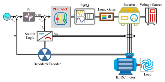
Figure 1.
Schematic diagram of the BLDC motor control system used novel current loop controller.
3. Design of FARC
3.1. Adaptive Internal Model Controller
The schematic diagram of TRC is shown in Figure 2. It should be noted that, E(z) is the input of TRC, U(z) is the output of TRC, Q(z) is the internal model controller in the traditional internal model element (TIM), z−N is the internal model delay, kr is the RC gain, zm is the phase compensator, S(z) is the high-frequency filter.
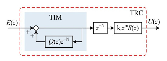
Figure 2.
Schematic diagram of the TRC.
To maintain the internal model element stability, a constant smaller than 1 is usually adopted as the traditional internal model controller Q(z). The sampling number N in the delay element z−N is determined by the sampling frequency f1 and the resonant frequency f2, which can be expressed as N = f1/f2. The BLDC motor speed is time-varying, which will make the sampling number N own the time-varying characteristic. Additionally, the sampling number N is composed by the integer part Ni and fractional part d. In this case, the TRC cannot exactly track the fractional signals. To address the drawbacks of the TRC, an adaptive internal model controller QA(z) based on Lagrange interpolation method is designed in this section, which can be expressed as
where M is the order of the interpolation polynomial, l(m) is the polynomial coefficient, m are natural numbers less than M.
When the interpolation polynomial order M is set to 1, 2 and 3, the coefficients of the interpolation delay element can be obtained, as shown in Table 1 [18].

Table 1.
The coefficients for the interpolation delay element.
To simplify the FARC structure, the value of M should be set to 2. Then, define AIM is the adaptive internal mode element used the adaptive internal model controller QA(z), and define TIM is the traditional internal mode element used the constant 0.95. The open-loop bode diagrams of AIM and TIM are shown in Figure 3.
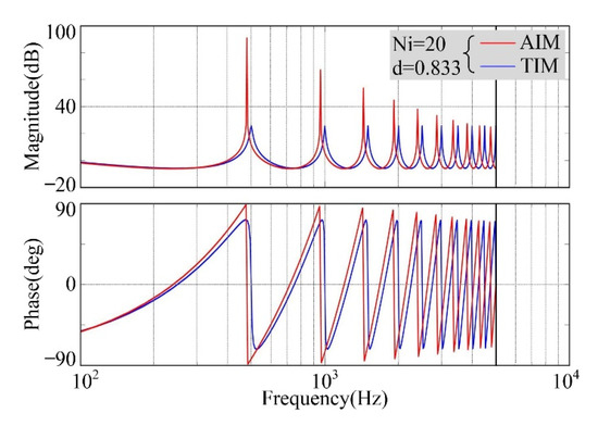
Figure 3.
Bode diagrams of different internal mode elements.
The 6th harmonics frequency is 480 Hz while the BLDC motor is operated at 1200 rpm, thus, the real sampling number N is 20.833, the integer part Ni is 20 and the fractional part d is 0.833. In this case, the first corresponding resonant frequency of TIM is close to 500 Hz, as shown in Figure 3. It is also shown in Figure 3 that the frequency offset is 20 Hz when compared to the target frequency. On the other hand, the first corresponding resonant frequency of AIM is 480 Hz. Thus, AIM can supply better frequency tracking performance for the RC controller in comparison with TIM. Additionally, the open-loop gain of AIM is larger than the open-loop gain of TIM, which can supply better harmonic suppression ability.
3.2. Novel Decomposition Rule
To obtain the optimal interpolation effect, the value of M is generally double of the delay order d [18]. Therefore, a novel decomposition rule for the sampling number N is proposed based on Lagrange interpolation theory in this section, and the sampling number N is recomposed as:
The 6th harmonics frequency is 660 Hz and the real sampling number N is 15.151, while the BLDC motor is operated at 1650 rpm. According to the traditional decomposition rule, the sampling number N can be decomposed into integer parts Ni and fractional parts d, and the values of Ni and d are 15 and 0.151, respectively. On the other hand, the sampling number N can be decomposed into Ni* and d*, and the values of Ni* and d* are 14 and 1.151, respectively. Defining the sampling number N in AIMT is decomposed into Ni and d, and defining the sampling number N in AIMN is decomposed into Ni* and d*. The open-loop bode diagrams of AIMT and AIMN are shown in Figure 4.
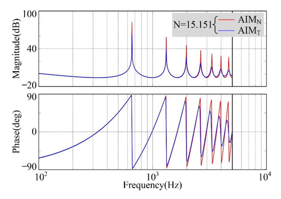
Figure 4.
Bode diagrams of adaptive internal mode elements with different decomposition rules.
It is obvious that AIMN can supply better frequency tracking ability than AIMT. Additionally, the open-loop gain of AIMN at the resonant frequency is larger than the open-loop gain of AIMT. In short, AIMN can supply better harmonic suppression ability in comparison to AIMT.
From the aforementioned analyses, the AIMN can be obtained through adopting the adaptive internal model controller QA(z) and the novel decomposition rule of the sampling number. Additionally, the FARC used the adaptive internal model element AIMN can be obtained, which possesses better frequency tracking performance and better harmonic suppression than AIMT, as shown in Figure 5.

Figure 5.
Schematic diagram of the control system.
It should be noted that, the reference value of the BLDC motor control system is defined as R(z), I(z) is the inverter transfer function, P(z) is the BLDC motor transfer function, EP(z) is the control plant, Y(z) is the output value of the control plant EP(z), EPm(z) is the equivalent control plant of FARC.
4. Analysis of the Novel Current Loop Controllers Parameters
4.1. PIC
Figure 5 shows that the control plant EP(z) is composed of the inverter and the BLDC motor. The inverter transfer function and the BLDC motor transfer function in continuous domain can be illustrated as
where kpwm the inverter magnification, Ts is the carrier period.
The frequency characteristics of the equivalent control plant EPm(z) with different kp values are shown in Figure 6. It is worth mentioning that the ki value is set to 0.
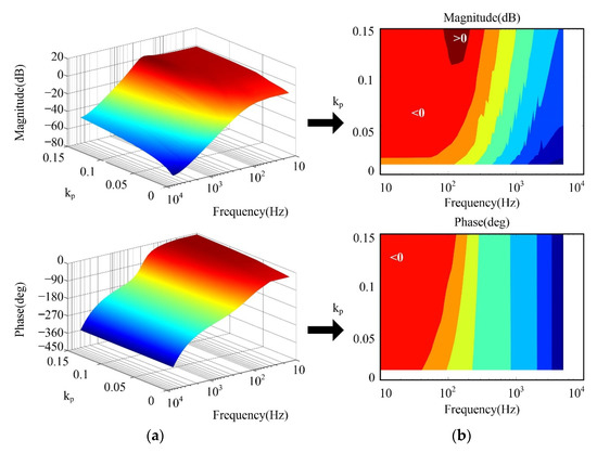
Figure 6.
Frequency characteristics of Gm(z): (a) Three-dimensional image; (b) Two-dimensional image.
With the increasing of kp value, it is difficult to guarantee the zero gain of amplitude-frequency characteristic for EPm(z), as shown in Figure 6. The gains of EPm(z) will become larger than zero in middle-frequency bands with a large kp value, which will introduce high amount harmonics in this frequency band. Additionally, the phase lag of EPm(z) can be reduced in high-frequency bands with increasing kp value. Therefore, to provide the desired frequency response for EPm(z), the value of kp should be set to 0.01 ≤ kp ≤ 0.12.
It is worth mentioning that the amplitude gains and phase of EPm(z) are slightly less than zero in low-frequency bands. In order to eliminate the offset in low-frequency band, the bode diagrams of EPm(z) with different ki values are analyzed, as shown in Figure 7. It is worth mentioning that the kp value is set to 0.08.
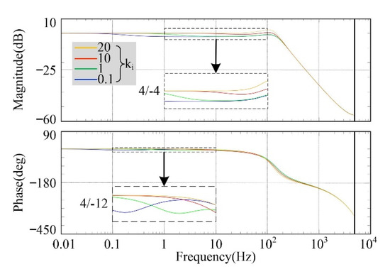
Figure 7.
Bode diagrams of EPm(z) with different ki.
With the increasing of ki value, the phase lag of EPm(z) can be reduced and the amplitude gain bias will be eliminated in low-frequency band, as shown in Figure 7. However, the amplitude gains and the rate of phase change will be too large in 100 Hz. Therefore, the value of ki should be set to 10. In conclusion, the appropriate values of kp and ki for the PIC are 0.08 and 10, respectively.
4.2. FARC
Figure 7 also shows that the harmonics of the equivalent control plant EPm(z) in high-frequency band cannot be suppressed effectively. In this case, the Butterworth filter is usually used as the high-frequency filter S(z) for the RC. To obtain the appropriate Butterworth filter order n, the frequency characteristics of the equivalent control plant EPm(z) with or without Butterworth filter are shown in Figure 8. It is worth mentioning that the Butterworth filter cut-off frequency is set as 2000 Hz (approximately 25 times of the fundamental frequency).
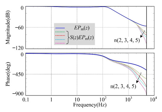
Figure 8.
Frequency characteristics of the control plant with or without Butterworth filter.
It is obvious that the transition bandwidth will become narrow and the phase lag will become large with the increasing of Butterworth filter order n. Hence, to obtain the satisfied harmonics filtering effect of EPm(z) in high-frequency band, and maintain the current loop simplicity at the same time, the order n of Butterworth filter is set to 4.
In order to compensate the phase lag in the high frequency band caused by S(z) and EPm(z), the phase compensator zm is added to FARC. To obtain the most appropriate beat m for the phase compensator, the bode diagrams of zmS(z)EPm(z) with the variation of m from 5 to 17 is analyzed, as shown in Figure 9.
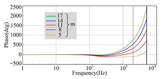
Figure 9.
Bode diagrams of zmS(z)EPm(z) with different phase compensators.
From Figure 9, it is observed that the required phase characteristic can be obtained while the value of m is set to 11. In this case, the phase characteristic in low-frequency band of the control system can be maintained at zero. Consequently, a large phase lag compensation in low-frequency band can be supplied by the phase compensator.
4.3. Composite Controller
The proposed FARC is located in the forward channel of the PIC. Hence, when the control signal is changed, the dynamic response performance of the current loop controller is selected as another forward channel, and the reference current feedforward channel can be established, which can improve the dynamic response performance of the current loop controller effectively. The proposed composite controller is shown in Figure 10.

Figure 10.
Schematic diagram of the composite controller.
It is obvious that the control signal error E(z) between the reference value R(z) and the feedback value Y(z) is small, while the BLDC motor is operated in steady state. Consequently, the output of the BLDC motor control system is mainly determined by FARC. On the other hand, the PIC can track the error immediately, while large control signal error E(z) appears. Nevertheless, the FARC will track the appeared error after one resonant period due to the existence of the lag element.
From the aforementioned analyses, the closed-loop transfer function of the current loop used composite controller can be given by
where RC(z) is the transfer function of FARC, which can be illustrated as
4.4. Analysis of the Control System Stability and Robustness
Based on Formula (12), the characteristic equation of the control system can be illustrated as
Based on the Lyapunov theory, the control system is stable if all characteristic equation eigen roots located in the unit circle. Hence, to maintain T(z) = 0, the composite controller should meet the following stable conditions: (1) all roots of 1+ PI(z)EP(z) = 0 located inside the unit circle; (2) 1 + RC(z)EPm(z) ≠ 0.
The establishment condition of the stable condition (1) can be described as the equivalent control plant EPm(z) poles located inside the unit circle. The pole distribution of EPm(z) is analyzed and shown in Figure 11a.

Figure 11.
(a) Pole distribution of Gm(z); (b) Nyquist diagrams of H(z) with different kr; (c) Nyquist diagrams of H(z) with different d.
It can be found that the poles of EPm(z) are all located inside the unit circle. In short, the composite controller meets the stable condition (1).
Additionally, the stable condition (2) can be rewritten as the following:
Based on minimum gain theory, the establishment condition of Formula (15) can be obtained as
From the aforementioned analyses, the RC stability with the variation of the RC gain kr should be analyzed. The analysis results for the Nyquist diagrams of H(z) with different kr are shown in Figure 11b. It is worth mentioning that the non-integer part is 0.833 while the BLDC motor is operated at 1200 rpm, as shown in Figure 3. From the Nyquist diagrams of H(z), it was found that loci of H(z) are always located in the unit circle while kr ≤ 0.8 and d = 0.833. Additionally, the stability margin is reduced with the increasing of kr value.
Furthermore, the proposed FARC stabilities with different BLDC motor operation speeds are also analyzed. For instance, the Nyquist diagrams of H(z) with different fractional part d values were studied, as shown in Figure 11c. It is obvious that the loci of H(z) are always located in the unit circle while 0.5 < d < 1.5 and kr = 0.7. Additionally, a certain margin between the root loci and the unit circle boundary can be retained, therefore, the control system can maintain a sufficient stability margin.
Consequently, the BLDC motor parameters are nonconstant under different operation conditions. The robustness for the control system used the composite controller with the variation of the BLDC motor parameters should also be analyzed. The analysis results for the Nyquist diagrams of H(z) with different phase winding resistances and different phase winding inductances are shown in Figure 12. It should be noted that the values of kr and d are set to 0.7 and 0.9, respectively.

Figure 12.
(a) Nyquist diagrams of H(z) with different R; (b) Nyquist diagrams of H(z) with different L; (c) Nyquist diagrams of H(z) with different R and L.
Figure 12 shows that the loci of H(z) are always located in the unit circle with different BLDC motor parameters. Additionally, the control system used the proposed composite controller can meet the stable condition (2).
5. Simulation
In order to verify the feasibility and the effectiveness of the proposed composite controller, the steady-state and dynamic response performances of the BLDC motor control system driven by different current loop controllers were analyzed through simulation studies. The BLDC motor control systems used the PIC, the TRC and the FARC are defined as S1, S2 and S3, respectively. The BLDC motor parameters are shown in Table 2.

Table 2.
The parameters of the BLDC motor.
5.1. Steady-State Performance
The steady-state performances of S1, S2 and S3 are compared under the same operating conditions. Firstly, the BLDC motor is operated under condition 1: the reference speed is 1500 rpm and the reference torque is 0.3 N·m. The waveforms of torque and phase A current of S1, S2 and S3 are shown in Figure 13.
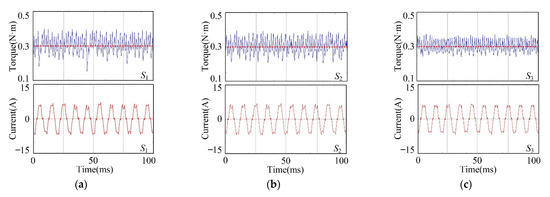
Figure 13.
(a) Waveforms of torque and phase A current of S1 under condition 1; (b) Waveforms of torque and phase A current of S2 under condition 1; (c) Waveforms of torque and phase A current of S3 under condition 1.
From the simulation results shown in Figure 13, it can be seen that the torque ripples of S1, S2 and S3 are 0.24 N m, 0.18 N·m and 0.13 N·m, respectively. Thus, the TRC can suppress the torque ripple by at least 25% in comparison with the PIC. Additionally, the FARC can suppress the torque ripple by at least 45% in comparison with the PIC.
Considering that the proposed strategy in this paper does not contain negative feedback links and is based only on the ideal model, it has insufficient universality. In order to analyze the suppression of current harmonics by the proposed control strategy, the control value of the current loop (im) is defined as the absolute value of the constant-flow phase current. For different sectors, the current value can be rewritten as
When the reference speed is set to 1500 rpm, the fundamental frequency is 1500 × 4/60 = 100 Hz. Figure 14 shows the comparison of the equivalent current spectrum at 6 k harmonics. It is worth mentioning that, when the frequency = 0 Hz, the current amplitude of S1, S2 and S3 is 5.706 N·m, 5.622 N·m and 5.593 N·m, respectively. The total harmonic distortion (all harmonics) of S1, S2 and S3 is 13.54%, 10.12% and 9.02%, respectively. Thus, the TRC can suppress the torque ripple by at least 25% in comparison with the PIC. Additionally, the FARC can suppress the torque ripple by at least 33% in comparison with the PIC. Hence, the current harmonics can be eliminated by the proposed FARC effectively.
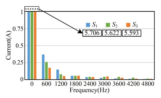
Figure 14.
Equivalent current spectrum diagram of S1, S2 and S3 under condition 1.
From the aforementioned analyses, it can be observed that the fractional part value of the sampling number N in AIMT is 0.667. According to proposed novel decomposition rule for the FARC, the fractional part d is along to the range of 0.5 to 1. Thus, the integer part values and the fractional part values calculated by different decomposition rules are the same. In order to evaluate the feasibility of the novel decomposition rule while the fractional part d is along to the range of 0 to 0.5, the reference speed of the BLDC motor is changed to 1300 rpm, and the reference torque is 0.3 N·m, and this operation condition is defined as condition 2. In this case, the values of the integer part Ni and the fractional part d calculated by the novel decomposition rule are 19 and 0.23, respectively. While the values of the integer part Ni* and the fractional part d* calculated by the novel decomposition rule become 18 and 1.23, respectively. The waveforms of torque and phase A current phase of S1, S2 and S3 are shown in Figure 15.
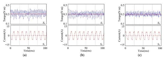
Figure 15.
(a) Waveforms of torque and phase A current of S1 under condition 2; (b) Waveforms of torque and phase A current of S2 under condition 2; (c) Waveforms of torque and phase A current of S3 under condition 2.
From the simulation results in Figure 15, it can be seen that the TRC can reduce the torque ripple by at least 17% in comparison with the PIC. Furthermore, compared to S1, S3 can reduce the torque ripple by at least 36%.
When set to 1300 rpm, the fundamental frequency is 1300 × 4/60 = 86.667 Hz. Figure 16 shows the comparison of the equivalent current spectrum at 6 k harmonics. The total harmonic distortion (all harmonics) of S1, S2 and S3 is 16.8%, 13.24% and 9.59%, respectively. Thus, the TRC and FARC can suppress the torque ripple by at least 21% and 42%, respectively, in comparison with the PIC. Therefore, the FARC shows superiority over the PIC and the TRC in reducing the torque ripples and current harmonics.
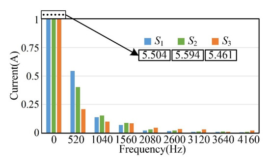
Figure 16.
Equivalent current spectrum diagram of S1, S2 and S3 under condition 2.
The harmonic component of commutation torque ripple of BLDC motor is mainly concentrated in the frequency of 6 kth harmonics (k = 1, 2, 3, …) [30]. Therefore, the proposed control strategy can also suppress the commutation ripple. Hence, condition 2 is selected for motor commutation analysis, and the Figure 17 is the current vector trajectory diagram of S1, S2 and S3. Obviously, the current vector trajectory changes from irregular sawtooth shape to standard regular hexagon, which can reduce the commutation torque ripple effectively.

Figure 17.
(a) Current vector trajectory diagram of S1; (b) Current vector trajectory diagram of S2; (c) Current vector trajectory diagram of S3.
5.2. Dynamic Performance
To evaluate the dynamic performance of the proposed composite controller, acceleration and deceleration simulations were carried out on S1, S2 and S3. Firstly, the BLDC motor torque is set to 0.3 N·m, and the reference speed is set to 900 rpm. Then the reference speed is increased to 1500 rpm within 0.2 s. Finally, the reference speed is reduced to 1200 rpm within 0.067 s. The simulation results are shown in Figure 18.

Figure 18.
(a) Speed trajectory of S1; (b) Speed trajectory of S2; (c) Speed trajectory of S3.
From Figure 18, it can be observed that the speed ripples of S1, S2 and S3 are 17 rpm, 16 rpm and 15 rpm, respectively. Hence, compared with PIC and TRC, the FARC can suppress the speed ripples and improve the operation performance of the BLDC motor control system effectively. Additionally, the FARC can maintain the reference speed signal accurately under acceleration condition and deceleration condition, as well as PIC and TRC. Therefore, the main advantage of traditional PIC, i.e., the reliable dynamic response, is maintained in FARC.
6. Conclusions
In this paper, FARC is designed in this paper to improve the alternating-current harmonics suppression ability for the current loop of the BLDC motor control system. Considering that the real sampling number may be not an integer, an adaptive internal model controller and a novel decomposition rule are proposed for FARC. Consequently, a novel current loop scheme that is a concatenation of PIC and FARC was established. Furthermore, a composite controller that added a froward channel in the proposed current loop was derived. The stability of the composite was verified through Lyapunov theory, and the design method of the composite controller parameters is also revealed in this paper.
The steady-state and dynamic simulation results validate that the proposed composite controller exhibits satisfied current harmonics suppression ability with outstanding torque and speed control performance, and nearly the same dynamic performance in comparison to PIC and TRC. Furthermore, the proposed FARC can also be used in active power filters, harmonics suppression for grid-connected inverters, and other industrial fields.
Future work will focus on the suppression of the transient current harmonics and the low frequency signal harmonics. It is worth mentioning that, due to the use of the reference current feedforward channel and PIC, the BLDC motor control system can realize the accurate track of the ramp speed signal. However, the speed ripple will increase briefly while the operation condition changes. Therefore, the speed feedforward and phase compensation need to be considered in future research. On the other hand, it is assumed that the accurate control signal can be supplied by the sensors. It is significant to study the suppression of the sensorless control noise, which can further increase the composite controller applicability.
Author Contributions
Conceptualization, T.Y. and Y.Z.; methodology, Y.Z.; software, Y.Z.; validation, T.Y.; formal analysis, Y.Z.; investigation, T.Y.; resources, T.Y.; data curation, Y.Z.; writing—original draft preparation, Y.Z.; writing—review and editing, T.Y. All authors have read and agreed to the published version of the manuscript.
Funding
This research was funded by the project is supported by Doctoral Scientific Research Foundation of Northeast Electric Power University (No. BSJXM-2020202).
Data Availability Statement
Not applicable.
Conflicts of Interest
The authors declare no conflict of interest. The funders had no role in the design of the study; in the collection, analyses, or interpretation of data; in the writing of the manuscript; or in the decision to publish the results.
References
- Yang, L.; Zhu, Z.Q.; Bin, H.; Gong, L. Spectral Analysis and Sideband Harmonic Cancellation of Six-Step Operation with Low Carrier–Fundamental Frequency Ratio for High-Speed Brushless DC Drives. IEEE Trans. Ind. Electron. 2021, 68, 7778–7792. [Google Scholar]
- Ishak, D.; Zhu, Z.Q.; Howe, D. Eddy-current loss in the rotor magnets of permanent-magnet brushless machines having a fractional number of slots per pole. IEEE Trans. Magn. 2005, 41, 2462–2469. [Google Scholar]
- Yang, L.; Zhu, Z.Q.; Bin, H. PWM Switching Delay Correction Method for High-Speed Brushless DC Drives. IEEE Access 2021, 9, 81717–81727. [Google Scholar]
- Sung, S.J.; Jang, G.H.; Lee, H.J. Torque Ripple and Unbalanced Magnetic Force of a BLDC Motor due to the Connecting Wire Between Slot Windings. IEEE Trans. Magn. 2012, 48, 3319–3322. [Google Scholar]
- Yuan, T.; Zhang, Y.; Wang, D. Performance improvement for PMSM control system based on composite controller used adaptive internal model controller. Energy Rep. 2022, 8, 11078–11087. [Google Scholar] [CrossRef]
- Yuan, Z.; Jin, G. Resonance Mechanism Analysis of Grid-connected Inverter Based on System Admittance. J. Northeast Electr. Power Univ. 2022, 42, 79–87. [Google Scholar]
- Zhonghua, Z.; Jianbo, Z.; Jingchao, F. Colpitts chaotic circuits of linear feedback control and adaptive feedback control. J. Northeast Electr. Power Univ. 2021, 41, 94–98. [Google Scholar]
- Shen, G.; Zhu, X.; Zhang, J.; Xu, D. A New Feedback Method for PR Current Control of LCL-Filter-Based Grid-Connected Inverter. IEEE Trans. Ind. Electron. 2010, 57, 2033–2041. [Google Scholar] [CrossRef]
- Weiguo, L.; Hongwei, L.; Xinyu, L.; Liming, C.; Lijun, G. Voltage synchronization signal detection technology based on improved SOGI-PLL. J. Northeast Electr. Power Univ. 2021, 41, 93–100. [Google Scholar]
- Son, I.; Lukman, G.F.; Shah, M.H.; Jeong, K.-I.; Ahn, J.-W. Design Considerations and Selection of Cost-Effective Switched Reluctance Drive for Radiator Cooling Fans. Electronics 2021, 10, 917. [Google Scholar] [CrossRef]
- Yanyan, L.; Yijun, W.; Huafeng, J.; Jingnan, W. Harmonic detection method of power system based on improved hilbert huang transform. J. Northeast Electr. Power Univ. 2021, 41, 119–123. [Google Scholar]
- Yang, F.; Jiang, C.; Taylor, A.; Kotrba, A.; Yetkin, A.; Gundogan, A. Design of a High-Efficiency Minimum-Torque-Ripple 12-V/1-kW Three-Phase BLDC Motor Drive System for Diesel Engine Emission Reductions. IEEE Trans. Veh. Technol. 2014, 63, 3107–3115. [Google Scholar] [CrossRef]
- Rutian, W.; Xiaofei, L.; Chao, S. Control strategy and modeling analysis of multi-resonant high-frequency link matrix rectifier based on double transformers. J. Northeast Electr. Power Univ. 2021, 41, 100–109. [Google Scholar]
- Hu, H.; Liu, K.; Wei, J.; Wang, H. Multirate model predictive current control of a permanent magnet synchronous machine for a flywheel energy storage system. Energy Rep. 2022, 8, 11579–11591. [Google Scholar]
- Jagiela, M.; Garbiec, T.; Gwozdz, J.; Kolodziej, J. Fast Steady-State Field-Circuit Model for SMPM-BLdc Motors Driven From 120° and 180° Quasi-Square Wave Inverters. IEEE Trans. Magn. 2016, 52, 1–4. [Google Scholar] [CrossRef]
- Darba, A.; de Belie, F.; D’haese, P.; Melkebeek, J.A. Improved Dynamic Behavior in BLDC Drives Using Model Predictive Speed and Current Control. IEEE Trans. Ind. Electron. 2016, 63, 728–740. [Google Scholar]
- Tang, M.; Odhano, S.; Formentini, A.; Zanchetta, P. Reuse of a Damaged Permanent Magnet Synchronous Motor for Torque Ripple and Acoustic Noise Elimination Using a Novel Repetitive Observer. IEEE Trans Ind. Appl. 2020, 56, 3790–3798. [Google Scholar] [CrossRef]
- Zhao, Q.; Chen, S.; Wen, S.; Qu, B.; Ye, Y. A Frequency Adaptive PIMR-Type Repetitive Control for a Grid-Tied Inverter. IEEE Access 2018, 6, 65418–65428. [Google Scholar]
- Xie, H.; Liu, Y.; Hou, Q.; Xu, X. Prediction of the remaining useful life of PEMFC based on particle filter and genetic algorithm. J. Northeast Electr. Power Univ. 2021, 41, 56–64. [Google Scholar]
- Wang, X.; Wang, A.; Wang, D.; Xiong, Y.; Liang, B.; Qi, Y. A modified Sage-Husa adaptive Kalman filter for state estimation of electric vehicle servo control system. Energy Rep. 2022, 8, 20–27. [Google Scholar]
- Enshu, J.; Qiushi, T.; Siyu, L.; Jiangdong, Z. Coordinated control strategy of MMC circulating current and capacitor voltage under unbalanced grid conditions. J. Northeast Electr. Power Univ. 2021, 41, 90–98. [Google Scholar]
- Zhang, Z.; Deng, Z.; Gu, C.; Sun, Q.; Peng, C.; Pang, G. Reduction of Rotor Harmonic Eddy-Current Loss of High-Speed PM BLDC Motors by Using a Split-Phase Winding Method. IEEE Trans. Energy Convers. 2019, 34, 1593–1602. [Google Scholar]
- Wang, H.; Shi, L.; Man, Z.; Zheng, J.; Li, S.; Yu, M.; Jiang, C.; Kong, H.; Cao, Z. Continuous Fast Nonsingular Terminal Sliding Mode Control of Automotive Electronic Throttle Systems Using Finite-Time Exact Observer. IEEE Trans. Ind. Electron. 2018, 65, 7160–7172. [Google Scholar]
- Xia, K.; Ye, Y.; Ni, J.; Wang, Y.; Xu, P. Model Predictive Control Method of Torque Ripple Reduction for BLDC Motor. IEEE Trans. Magn. 2020, 56, 1–6. [Google Scholar]
- An, Q.; Zhang, J.; An, Q.; Shamekov, A. Quasi-proportional-resonant controller based adaptive position observer for sensorless control of PMSM drives under low carrier ratio. IEEE Trans. Ind. Electron. 2020, 67, 2564–2573. [Google Scholar]
- Huang, M.; Deng, Y.; Li, H.; Wang, J. Torque ripple suppression of PMSM using fractional-order vector resonant and robust internal model control. IEEE Trans. Power Electron. 2021, 7, 1437–1453. [Google Scholar]
- Zhao, Q.; Ye, Y. A PIMR-Type Repetitive Control for a Grid-Tied Inverter, Structure, Analysis, and Design. IEEE Trans. Power Electron. 2018, 33, 2730–2739. [Google Scholar] [CrossRef]
- Qiangsong, Z.; Shasha, C.; Xiaoyu, Z.; Xiaolei, W.; Shuanghong, W. Analysis and design of combination controller based on repetitive control and proportional control for harmonics suppression of grid-tied inverters. Trans. China Electrotech. Soc. 2019, 34, 5189–5198. [Google Scholar]
- Ye, J.; Liu, L.; Xu, J.; Shen, A. Frequency adaptive proportional-repetitive control for grid-connected inverters. IEEE Trans Ind. Appl. 2021, 68, 7965–7974. [Google Scholar]
- Xuliang, Y.; Jicheng, Z.; Jingfang, W.; Shengqi, H.; Yishu, J. Research on Suppressing Commutation Torque Ripple of Brushless DC Motor Based on an Auxiliary Step-up Front End. Proc. CSEE 2020, 40, 3021–3031. [Google Scholar]
Publisher’s Note: MDPI stays neutral with regard to jurisdictional claims in published maps and institutional affiliations. |
© 2022 by the authors. Licensee MDPI, Basel, Switzerland. This article is an open access article distributed under the terms and conditions of the Creative Commons Attribution (CC BY) license (https://creativecommons.org/licenses/by/4.0/).