Article

A Pseudoinverse Siamese Convolutional Neural Network of Transformation Invariance Feature Detection and Description for a SLAM System

1
Unmanned Systems Research Institute, Northwestern Polytechnical University, Xi’an 710072, China
2
School of Aerospace Engineering, Xi’an Jiaotong University, Xi’an 710049, China
*
Author to whom correspondence should be addressed.
Machines 2022, 10(11), 1070; https://doi.org/10.3390/machines10111070
Submission received: 26 September 2022 / Revised: 6 November 2022 / Accepted: 10 November 2022 / Published: 12 November 2022
(This article belongs to the Section Robotics, Mechatronics and Intelligent Machines)

Abstract

:
Simultaneous localization and mapping (SLAM) systems play an important role in the field of automated robotics and artificial intelligence. Feature detection and matching are crucial aspects affecting the overall accuracy of the SLAM system. However, the accuracy of the position and matching cannot be guaranteed when confronted with a cross-view angle, illumination, texture, etc. Moreover, deep learning methods are very sensitive to perspective change and do not have the invariance of geometric transformation. Therefore, a novel pseudo-Siamese convolutional network of a transformation invariance feature detection and a description for the SLAM system is proposed in this paper. The proposed method, by learning transformation invariance features and descriptors, simultaneously improves the front-end landmark detection and tracking module of the SLAM system. We converted the input image to the transform field; the backbone network was designed to extract feature maps. Then, the feature detection subnetwork and feature description subnetwork were decomposed and designed; finally, we constructed a convolutional network of transformation invariance feature detections and a description for the visual SLAM system. We implemented many experiments in datasets, and the results of the experiments demonstrated that our method has a state-of-the-art performance in global tracking when compared to that of the traditional visual SLAM systems.

1. Introduction

Simultaneous localization and mapping (SLAM) [1] is a hot research topic in both the computer vision and robotics communities [2]. The development and progress of the SLAM system are widely applied in many fields, including civil industry, military industry, agriculture, and the security protection industry. Examples of these systems include the sweeping robot, unmanned vehicles, autonomous navigation (UAV), autonomous navigation in unmanned missiles, autonomous unmanned system cooperative operation, and other applications. [1,2,3] The SLAM system is a crucial part of automatic driving and autonomous navigation, and its working steps mainly include motion tracking, local mapping, and loop-closure detection. [1,2,3] Feature points are extracted from the images captured by the camera and pose and motion are estimated according to the geometric relationships between the feature points and the map points to realize the positioning function of the visual SLAM system. [1,2,3] Therefore, the key to accurate pose estimation and motion tracking, without loss, is an accurate detection and a correct matching of feature points.
Feature points can be expressed independently in texture and are often the points where the direction of the object boundary changes suddenly or the intersection between two or more edge segments. It has a clear position or is well positioned in the image space. The accurate detection and correct matching of feature points are the core steps needed for the whole SLAM system.
In the actual application of SLAM technology, such as in visual navigation and positioning, as well as in the application platforms, such as unmanned vehicles and unmanned aerial vehicles, the large view angle of unmanned vehicles quickly makes sudden turns, and the flight trajectory of unmanned aerial vehicles rapidly changes, which often leads to problems, such as large camera viewpoint changes and image frame sparsity. In such complex application scenarios, traditional SLAM algorithms often lose track due to a matching failure, which leads to the failure of visual navigation and the positioning of smart devices, resulting in a limitation in the application of smart devices. In a complex environment, designing a set of features with scale, rotation, repeatability, environmental change, and illumination invariance is the core problem of feature points. The features from accelerated segment (FAST) [4] corner detection method is adopted in the SVO [5] system. Instead of calculating the descriptors, block matching is carried out according to the 4 × 4 small blocks around the key points, realizing the tracking matching of the key points. [5] In PTAM [6], FAST [4] corner is used for feature extraction, and the parallel operation of motion tracking and mapping is performed. The speeded-up robust feature (SURF) [7] corner detection method is adopted in RTAB-Map [8] to realize a feature-based visual odometer and bag-of-words model for loop-closure detection. The features used in the SLAM schemes are easily affected by illumination and angle of view changes and have low feature robustness to weak or repeated textures. Therefore, feature matching is prone to loss and error.
ORB-SLAM2 [2] and ORB-SLAM3 [3], are two of the best traditional SLAM algorithms, which adopt the ORB [9] feature for feature detection. The ORB feature adopts FAST as a corner point and BRIEF as a descriptor, which has the advantages of rotation and scale invariance [10]. However, the ORB-SLAM system has shortcomings, such as centralized feature point detection, poor robustness of pose calculation, and weak tracking ability in complex environments, such as texture, viewing angle, illumination changes, large pose calculation errors, and easy loss.
Deep learning has achieved good development in various fields. In computer vision, some outstanding work has been conducted for feature detection, feature matching, position recognition, and depth estimation. In particular, convolutional neural networks have shown advantageous performance in almost all image processing tasks. [11,12,13,14,15] Among them, the Siamese convolutional network has been well developed in object tracking and loop closure detection and has achieved excellent results [16,17]. To solve the problems of traditional SLAM systems, the application of Siamese convolutional neural networks [16,18] in SLAM has achieved good results, such as feature detection and similarity detection in complex scenes. However, most of the feature points detected by existing methods have no descriptors or cannot describe the feature points well for cross-viewing, illumination changes, and weak textures. However, detectors and descriptors are required to match map points in SLAM systems, and most deep learning algorithms do not have the transformation invariance feature detection and the description or both. In addition, the invariance of illumination, angle of view change, and weak texture are not superior, and it is easy to lose track. Therefore, to solve these problems, we proposed a new multifunction feature extraction and feature description pseudoinverse Siamese network for the SLAM system; this new network has cross-view, illumination, and texture invariance for feature detection and description in a complex environment.
In this paper, our system uses the front-end design transformation module and feature extraction of the backbone network module, linking the feature point detector and the descriptor sharing network, with data sharing. Finally, the whole network is trained by designing a loss function and building it into a base Siamese convolutional neural network of transformation invariance feature detection, and a description of a SLAM system.
Therefore, our main contributions in this paper can be summarized as follows: (1) We proposed a multifunctional feature detection and description based on a Siamese convolution and compared it with traditional methods, for example, illumination, angle, and texture invariance in complex environments. (2) Since the convolutional neural network does not have transformation invariance, the method that we proposed learns an invariant spatial transform and a viewpoint covariant detector and descriptor. (3) We designed a single network to learn both feature detection and response feature descriptor calculations with a self-supervised approach, as shown in Figure 1. (4) We proposed a novel SLAM system based on a pseudoinverse Siamese convolution, which effectively solves the problems of traditional SLAM systems, such as less feature detection, less robust transformation invariance, easy to lose track issue, and improves the localization and mapping performance of the SLAM system.

2. Related Work

The ORB descriptor is a binary vector that allows high-performance matching. It can work in both indoor and outdoor environments and supports relocation and automatic initialization [1]. ORB features work well in traditional SLAM systems and are a state-of-the-art traditional algorithm. However, in complex or changeable scenes, such as inadequate light, excessive illumination, angle of view change, and weak texture, their performance is not stable or may even be unable to work. In multitask features [15], a deep-learning visual SLAM system, based on a multitask feature extraction networks, and self-supervised feature points is proposed. The system makes full use of the advantages of deep learning to extract feature points, and the CNN structure of the detection feature points and descriptors is simplified. GCN-SLAM [11] proposed a new learning scheme for generating geometric correspondences to be used for visual odometry. However, they did not work on cross-views, lighting, and texture invariance in complex environments.
SuperPoint [19] proposes a self-supervised training framework for point-of-interest detectors and descriptors suitable for a large number of multi-view geometry problems in computer visions. Different from the patch-based neural network, it uses a full convolution model to operate on the full-size image and computes the pixel level position of interest points and related descriptors in a forward pass. The haplotropic adaptive, multiscale, multi-haplotropic method is used to improve the repeatability of point of interest detection and performs cross-domain adaptation. However, descriptors are not robust to cross-view and illumination invariances. GIFT [20] introduces a novel dense descriptor, with a provable invariance to a certain group of transformations. In this method, a descriptor with transformation invariance is proposed to perform feature description calculations on the corresponding feature points but without a feature point detection function. LIFT [21] introduces a novel deep learning network architecture that combines the three components of standard pipelines for local feature detections and descriptions into a single differentiable network. Patch2Pix [22] proposed a detect-to-refine method, where it first detects patch-level match proposals and then refines them by a refinement network. The refinement network refines match proposals by regressing pixel-level matches from the local regions, defined by those proposals, and jointly rejects outlier matches with confidence scores. Through the two steps of rough matching and fine matching, the method realizes the detection and matching of feature points and achieves a good performance. However, these methods do not have transformation invariance and are not robust to changes in perspective. In addition, there is no computational descriptor, and these features cannot be applied to the local map matching in the SLAM system and bundle adjustment (BA) [23] optimization, so they are not suitable for SLAM systems.
Ref. [24] proposed a LIFT-SLAM, which achieved ideal results in scenes with rich textures, and this method can achieve good results in general environments. The LIFT-SLAM proposed in [24] uses LIFT as the feature extraction module at the front end. LIFT-SLAM is not proven in complex scenes, such as illumination, viewpoint, and low-texture scenes. However, there are various complex application scenarios in real life, such as the sudden turn of an unmanned car, the sudden change in course of a UAV, etc. Other applications, such as relocation and loop detection, are performed at different views or at larger views. [25] proposed a kind of RGB-D image sparse visual odometer model, which proposed the use of edge characteristics to minimize photometric adjustments in positional errors; based on the characteristics of the different traditional methods, this method, uses the edge of the image feature extraction method, and introduces each edge point using the exposure degree of a prior probability. The joint photometric error minimization and probabilistic models are used to improve sparse point extraction. It makes feature matching more robust and computationally efficient. However, in complex scenes, such as scenes with low texture and unclear edges, sparse feature points are often few and cannot meet the needs of SLAM algorithm motion tracking. In particular, the photometric adjustment method has a strong photometric consistency assumption, so it is not applicable in complex environments.
In this paper, we proposed a pseudoinverse Siamese convolutional neural network of transformation invariance feature detection and a description for SLAM systems in complex environments. We combined the excellent advantage of convolutional networks in feature descriptors and feature detection. The backbone network structure and feature detection and description submodule based on group features are designed. At the same time, the single neural network structure has feature detection and description with shared parameters.

3. Method

In this section, we first describe the proposed general framework of the method. Second, a pseudoinverse Siamese convolutional network of the transform invariant feature extraction backbone network is described in detail. Third, the feature detector subnetwork and feature descriptor subnetwork are described. Finally, we cover a novel SLAM system by combining a convolutional neural network in detail.

3.1. Overall Framework

A pseudoinverse Siamese convolutional neural network of transformation invariance feature detection and a description for the SLAM system that we propose, includes a design of a backbone network for feature extraction and then a design for two branch networks based on Siamese networks; a feature detector subnetwork, and a feature descriptor subnetwork. The backbone network is shared by two branch networks, and then the feature detector subnetwork is used to detect feature points on the input image. The feature descriptor subnetwork is used to describe the detected feature points and forms feature vectors, with information being sharing between them. Second, the tracking module and local mapping module are designed to jointly contribute to the map.
As shown in Figure 2, the input image was transformed to form an image group, and then the backbone network module was used to extract features from the image group. The extracted features are inputted into the feature detection module and the feature description module for feature detection and description, respectively, again sharing their information. This tracking module preprocesses the Siamese feature points, descriptors, and depth picture, generating coordinates for pose prediction, local map tracking, and determining new keyframes. The local mapping module is used to insert and delete new keyframes, create and delete new points, and perform local BA operations. The map module includes map points, keyframes, a visibility graph, and a spanning tree.

3.2. The Backbone Network of Feature Detection and Description

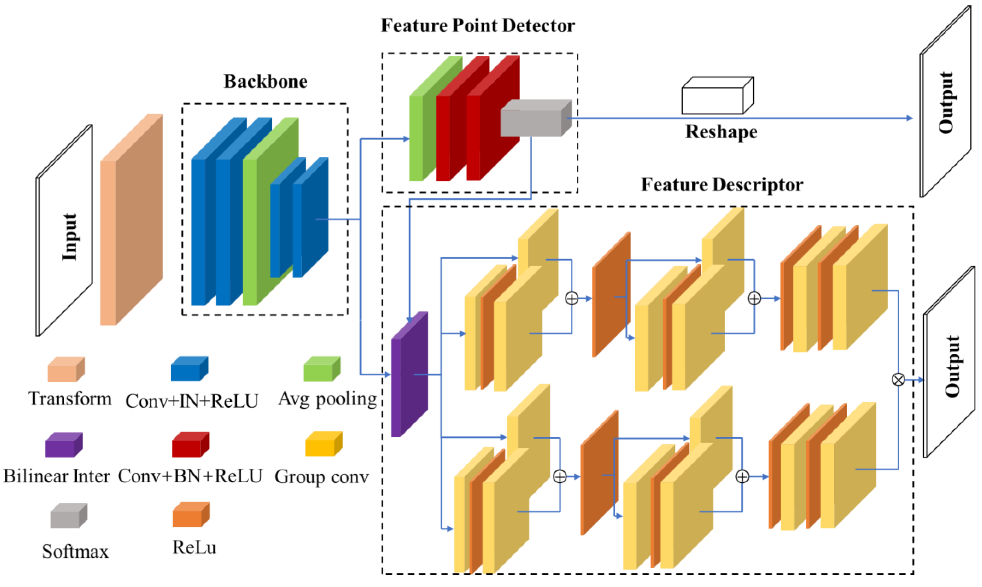
As shown in Figure 3, our backbone network adopts a neural network design in the style of vanilla CNN to reduce the spatial dimension of the sampled images through convolution, pooling, and nonlinear activation functions. First, an image transformation module is designed to transform the input image according to the image perspective change, illumination, scale, and rotation. Given an image I, and by transforming tT, output I′ ∊ G, and image Group G is obtained by transformation module T. Then, two convolution layers are followed by the transformation module. Each convolution layer is followed by a ReLu nonlinear activation function. Between the two convolutional layer networks and activation functions, we did not follow the batch normalization (BN) layer, but the instance normalization (IN) layer. BN is suitable for discriminant models, such as image classification models. The BN layer focuses on the normalization of each batch to ensure the consistency of the data distribution, and the result of the discriminant model depends on the overall distribution of the data. However, BN is sensitive to the size of the batch. Since the mean and variance are calculated on a batch each time, if the batch size is too small, the calculated mean and variance are not enough to represent the entire data distribution. IN is useful in generative models, such as image style migration. Because the results generated by images mainly depend on an image instance, the normalization of the whole batch is not suitable for image stylization. The IN layer in style migration can not only accelerate model convergence but also maintain the independence of each image instance. We followed an average pooling layer for down sampling. Finally, we convolved two convolution layers with the ReLu function for the nonlinear activation function as above and then the IN layer between the convolution layer and the activation function, as shown in Figure 3.
Given an input image I, O g r o u p = i = 0 m t i I , transform t0, t1, t2tmT warped images are used to form a group of transform image Groups O0, O1, O2OmOgroup. The backbone network feature extractor calculates a feature map for each image in the transformation image group. Warped images correspond to feature maps one by one, and each distorted image corresponds to a feature map. Feature points can extract a feature vector from all the feature maps to form the feature vector group. This is performed in the feature descriptor subnetwork. In addition, we input the feature map extracted from the original image into the feature detector subnetwork for the detection and calculation of feature point positions.

3.3. The Feature Detector Subnetwork

The feature detector subnetwork is designed as a feature detector to compute feature-point positions. As a decoder, the feature detector subnetwork first follows one average pooling layer and two convolution layers, as shown in Figure 3. Input image I through two convolution layers and then into channel-wise softmax. For each input pixel pI, the decoder outputs the probability of each pixel point as a feature point:
p y = i = e z i j = 0 k 1 e z j , i 0 , , k 1
where p is the probability that the pixel is a feature point. At the last convolution layer, the data of each channel are fused, and the dimension is reduced by the 1 × 1 unit convolution instead of the pooling layer and striding. The advantage of this method is to reduce the amount of computation and avoid data loss and distortion. The input image is convolved onto 64 channels channel-wise, and channel-wise convolution slides on the channel dimension, which cleverly solves the complex fully connected characteristics of the input and output in the convolution operation; however, it is not as rigid as grouping convolution. Corresponding to the nonoverlapping 8 × 8 region in 64 channels, the last channel is used to represent the response value of the 8 × 8 region after 64 channels. Finally, the feature point position is put on the original size diagram, and the feature point coordinate position p (x, y) is output.

3.4. The Feature Descriptor Subnetwork

In this section, we design the feature descriptor subnetwork, which extends the group convolution [26] features of feature modules. For the feature map group output by the backbone neural network, the feature detected by the feature detector subnetwork and the feature descriptor subnetwork apply to the feature detected by the feature detector subnetwork to perform bilinear interpolation to the feature map. As the feature map group is the transform group image, formed after the transformation of the original image and then obtained by convolution, the same transformation is also applied to feature point location detection of the original image. The feature points are transformed into the corresponding feature maps one by one, and the corresponding feature map is interpolated according to bilinear interpolation. Group convolution of the feature group vector is processed according to the group convolution neural network [26]. The group convolution module is divided into two groups of convolutions with both A and B as eight layers and convolves the group feature group vectors. Group features [20,26] and the bilinear model [27] are merged to generate descriptors, as shown in Figure 3:
G m a p i = ψ B t i I , t i P B I
where ψ is the bilinear interpolation function, B is the backbone network feature detection function, t i is the transformation and P is the feature point detector. There are many ways to achieve transformation invariance. However, in feature description, equivariant invariance is more important than invariance because invariance is not a very good description of the properties in different spatial states. Group convolutional neural networks can learn feature map equivariant invariance features. So that means:
ψ t i x = t i ψ x
where t i and t i need not be the same. In other words, although feature maps undergo different transformations, such as the angle of view and illumination, their descriptors are the same. If d represents the descriptor of an image, d′ represents the descriptor after transformation, and then d = d′. To obtain the descriptors d, the pooling function P aggregates the bilinear feature pass point location through the image. The calculation process of this descriptor is as follows:
d = i , j m , n t i ,   t j ϵ T f A ψ t i x · f B ψ t j x d t
Here, fA and fB represent feature functions.

3.5. Loss Functions

The network loss function designed by us is composed of two parts: one is the loss function Lp of feature points, and the other is the loss function Ld of the descriptor corresponding to feature points. We use pairs of synthetically warped images that have the ground truth correspondence from a randomly generated homography H that relates the two images. Since there is information sharing between the two parts, given a pair of images, we introduce weight terms to the final loss function, and the total loss function is the weighted Lsum of the two.
  • Point loss
The feature point loss Lp, which we adopt is the cross-entropy loss, is shown in the formula below:
L p = 1 H c W c i = 1 j = 1 H c , W c l o g e x p x i , j , y m = 1 65 e x p x i , j , m
Here, HC and WC are the height and width of the rectangular region for the cross-entropy calculation, respectively, and x is the value of the rectangular region at position (I, j) in different channels m.
  • Descriptor loss
In the loss of descriptor, triplet loss is adopted, which minimizes the distance between d and dp and maximizes the distance between d and dn. The formula is as follows:
L d = m a x d d p 2 d d n 2 + θ ,   0
Here, d is the descriptor in an image, dp is the true value descriptor, dn is the false descriptor, and θ is a margin between positive and negative pairs.
  • Total loss
The final total loss is the sum of the feature point loss and descriptor loss, and α is used to balance the loss ratio:
L s u m = L p + L p + α L d
where Lp is the feature point loss after transformation.

3.6. A Siamese Convolutional Network of Transformation Invariance Feature Detection and Description for a Slam System

As shown in Figure 4, the proposed method is constructed based on ORB-SLAM2 [2] and replaces the front-end feature detection description and matching part. The proposed method combines the advantages of a convolution network for feature detection and description and improves the robustness and stability of invariants, such as cross-viewing angle, texture, and illumination. They are constructed by a single network to realize the information sharing of both the feature detection and feature description and improve the validity of the information.
For the sake of the simplicity of the experiment, we did not add the loop closure detection part and the global BA part into the system. Therefore, our system mainly consists of the front end of the tracking and local map parts.

3.6.1. Tracking

The tracking thread runs in the main thread of the system and is responsible for feature extraction, pose estimation, map tracking, and keyframe selection for each frame of the input image. The proposed method uses the RGB-D camera image data as the processing object, which is also applicable to the stereo camera and mono camera. Here, we discard the original feature matching method and adopt the Siamese convolutional neural network method to feature match the descriptors generated. Then, a nonlinear optimization method is used to minimize the reprojection error and optimize the tracked pose.
We followed the keyframe method in ORB-SLAM [1] and ORB-SLAM2 [2] and divided the feature points into close-range map points and long-range map points. Due to the noise and large error of long-range points, to ensure the accuracy and stability of pose estimation, we must carry out pose estimation under the condition that there are enough close-range feature points. Therefore, we use this as the judgment criterion for whether to insert new keyframes. In addition, the current frame has a certain movement with the last keyframe to avoid the waste of computing resources caused by the static picture. To ensure the accuracy of pose estimation, a suitable number of feature points should be provided.

3.6.2. Local Mapping

The local mapping thread is responsible for processing new keyframes, eliminating map points, adding map points, integrating map points, local BA optimization, and eliminating keyframes. In the keyframe insertion module, it is used for keyframe insertion. First, update the common view, insert the keyframe node, and update and insert the edges between the common view map points and other local keyframes. Then, the connection relationship between each keyframe is updated.
Although the high-quality feature points detected in the current keyframe have not been matched successfully, they are added to the map points, according to the tracking position and pose transformation relationship, to maintain the number and scale of local map points by the following formula:
X w Y w Z w = T c w X c Y c Z c
In the local bundle adjustment section, pose and feature points are optimized, and pose and local map points of local key frames are optimized at the same time. All variables to be optimized are put into variable x together, as shown in Equation (9), and the cost function is shown in Equation (10):
x = T 1 , , T m , p 1 , , p n T
J x = 1 2 f x + Δ x 2 1 2 i m j n e i j + J x T i Δ T i + J x p j Δ p j 2
Take the square root of the diagonal elements of JTJ and form a nonnegative diagonal matrix A. Then, we solve the delta equation:
m i n Δ x k 1 2 f x k + J x k Δ x k 2 + λ 2 A Δ x 2
H + λ A T A Δ x = g
Here, λ is the LaGrange multiplier. To maintain the scale and computation of the local map, some local keyframes, that are not in the current frame, can be seen in common and nonadjacent keyframes, which are then deleted from the local keyframe.

4. Experimental Results

4.1. Implementation Details

In this section, we present some experimental details. In the feature point detection and description network, we designed the image transform module. We set up the main network structure with a 5 × 5 convolutional layer of 16 units followed by a 5 × 5 convolution layer with 32 units, an IN layer, and ReLU nonlinear activation function. This is followed by a 2 × 2 average pooling layer. The average pooling layer is followed by two layers of 5 × 5 convolutional layers of 32 units, which include an IN layer and a ReLU nonlinear activation function. The feature point detector subnetwork has a 3 × 3 convolutional layer of 256 units, which includes a BN layer and a ReLU nonlinear activation function. Subsequently, followed by a layer of a 1 × 1 convolutional layer of 65 units and then a softmax layer, a reshaping was performed. In the feature point descriptor subnetwork, we adopt group convolutions [20] to extract description features, and the group convolutions are divided into two branches. This subnetwork architecture has eight convolution layers of 64 units, except for the last layer. The last layer of each branch is 8 and 16, respectively. In addition, each branch has two 1 × 1 convolution layers, and the other layers are 3 × 3. Finally, the group features of the two branches are both merged through the bilinear pooling layer, and the network structure is shown in Figure 3.
The proposed method is trained on the MS-COCO dataset [28], and the self-supervised learning method is adopted to train model. A reasonable transformation matrix was used to transform the input image into pseudoground truth image pairs to train the model. Standard image enhancement methods such as scale, rotation, brightness, and motion blur are also applied to transform images to increase the number of datasets. Since the SLAM system is a motion solution method, perspective change, illumination, texture, and motion blur are crucial to the system. We trained the model based on the torch framework, set the hyperparameters, learning rate to 0.001, mini-batch 32, and used the ADAM [29] optimizer.
The test platform is equipped with an Intel i9-7900X CPU @ 3.30 GHz × 20, 64 GB RAM, and 2080Ti GPU hardware platform and ubuntu18.04 system for the experiments. The proposed approach was evaluated on the TUM dataset [30] and HPSequences dataset [31]. The TUM dataset includes data of different scenes, scenes with texture, scenes without texture, near scenes, and far scenes. The HPSequences dataset contains data about illumination changes and perspective changes, which can be tested separately. We use the self-supervised learning proposed in [19] to train detectors and descriptors without manual data annotation, which reduces the complexity and workload of manual annotation, as shown in Figure 1.

4.2. Feature Point Detection and Matching Experiments

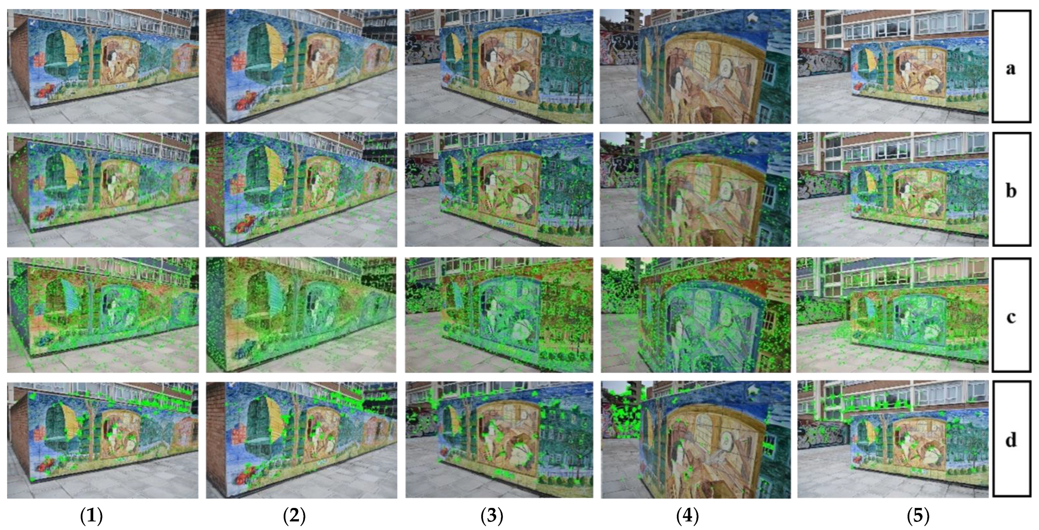
The proposed method (Figure 5b) compares feature point extraction with the state-of-the-art deep learning method Superpoint [19] (Figure 5c) and the traditional method ORB (Figure 5d). We detected feature points from five perspectives in the same scene, and the green points represent the detected feature points, as shown in Figure 5. The proposed method has a more uniform feature point distribution and detection rate than the traditional methods. Although the feature points detected by Superpoint are relatively dense, the experimental results show that the detected feature points are not stable, which can be proven in the following matching experiment.
As shown in Figure 6, we implemented matching experiments on cross-view scenes, and the green lines represent matches of the corresponding feature points. As you can see from above, our method has more dense and correct feature point matching when compared with Superpoint and ORB features at five different perspectives. Especially in the large viewing angle scenes in Figure 6(1–3) and Figure 6(1–4), both Superpoint and ORB have several mismatched samples.
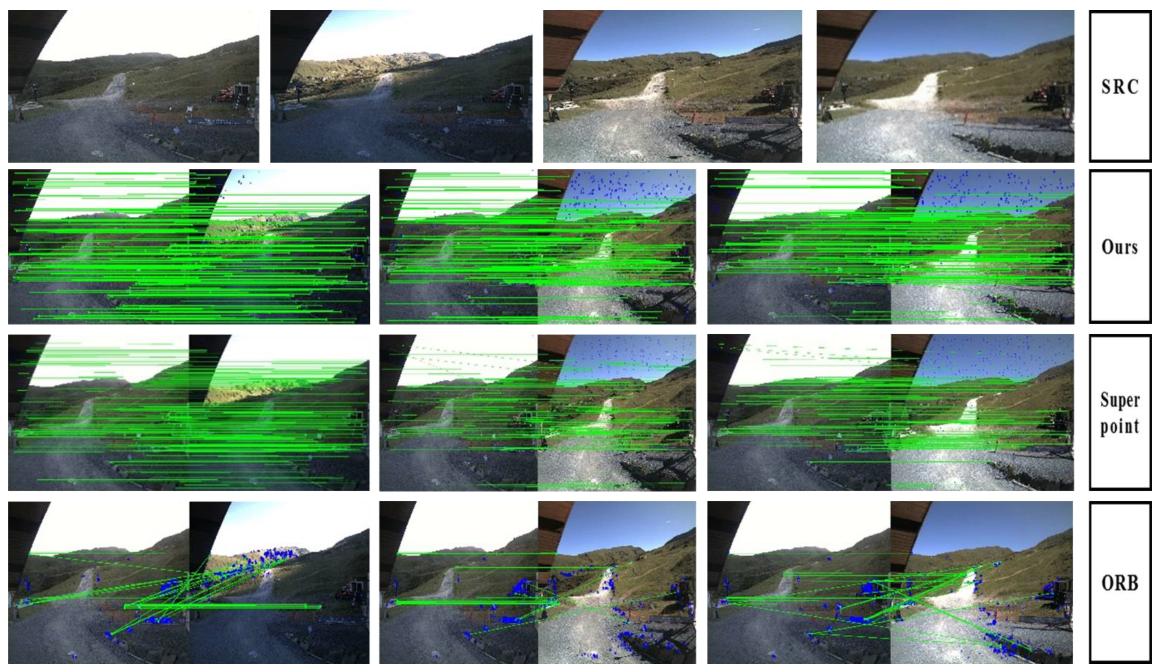
Our method was compared with ORB and Superpoint under dark, slightly dark, slightly bright, and Super bright conditions, as shown in Figure 7. As seen from the experimental results, our method still shows a higher detection and matching rate and illumination invariance under the four lighting conditions, while the ORB and Superpoint show low illumination invariance and matching rates.
We also implemented comparative experiments on weak and rich textures, as shown in Figure 8. For rich texture, all three methods seem to give good results on feature detection and matching. However, the ORB and Superpoint performed poorly with weak textures due to their high dependence on texture, corners, and edges. In contrast, our proposed method is less dependent on them, so it still shows a state-of-the-art performance on both detection and matching.
The SLAM system solves the camera motion directly according to the geometric relationship of map tracking, which corresponds to the feature matching and tracking in the image. Moreover, in the process of optimizing the pose, the reprojection error of the matching result is directly used as the optimization objective function for optimization. Therefore, the accuracy of the geometric relationship directly affects the solution accuracy of the camera motion, that is, the trajectory accuracy of the camera motion. In Table 1 we adopt the HPatches dataset for the evaluation report of the geometric relationships. In the experiment, we use the Random Sample Consensus (RANSAC) algorithm, to estimate the geometric relationship. We report the percentage of correctly estimated homographies for which the average corner error distance threshold is set to 1/3/5 pixels. From the experimental results in Table 1, we can see that our proposed method obtains superior homography results, which proves the effectiveness of the proposed method on geometric relations.
To further illustrate the impact of correct matching and successful matching on the SLAM system, as shown in Figure 9, we also count the success of our proposed method in 100 images in 20 different scenes with different perspectives, different illumination datasets, etc. The match performance is compared with the excellent deep learning method SuperPoint and the traditional method ORB. As shown in the figure, the abscissa is the number of images, and the ordinate is the number of images successfully matched. The yellow line is the actual ground truth, the orange line is the matching result of our proposed method, the blue is the SuperPoint algorithm, and the gray is the ORB algorithm. Figure 9a shows the matching result when the error ε = 1, Figure 9b shows the matching result when the error ε = 3, and Figure 9c shows the matching result when the error ε=3. It can be seen from the results in these figures that our proposed method achieves excellent successful matching results whether it is ε = 1, ε = 3, or ε = 5.

4.3. Performance for Pose Estimation Experiments

In this part, we conducted a comparative experiment on ORB-SLAM2 [2] but not on ORB-SLAM3 [3] because ORB-SLAM2 and ORB-SLAM3 are the same in this part, but a fragmented submap module is added. The function of this module is to lose track. At the same time, the submap is stored first for subsequent map splicing.
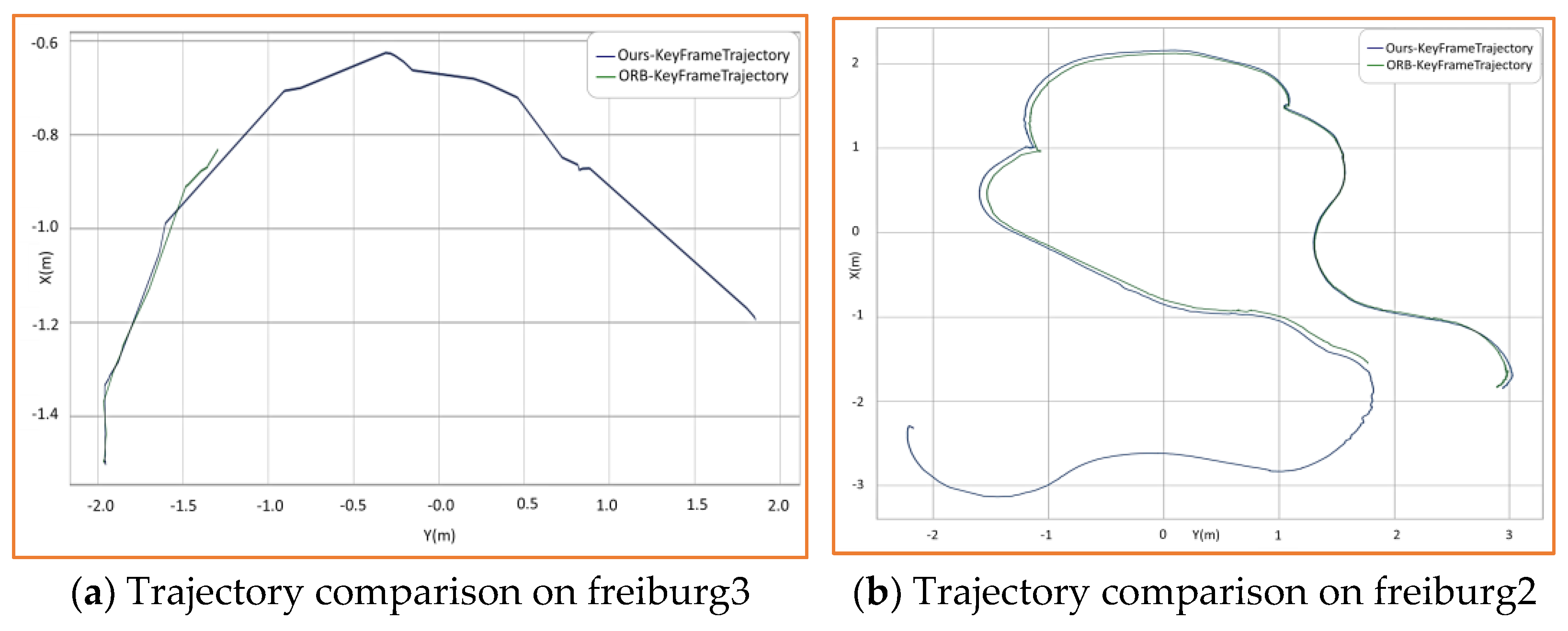
In Figure 10, we compared the frame-to-frame tracking trajectory estimation between our proposed method and ORB-SLAM2. Figure 10a is the comparison experiment in the no-texture area, and Figure 10b is the comparison experiment in the scene of illumination change and angle of view change. As seen from the two figures, our method, the blue line in the picture, has a more complete trajectory, while the traditional ORB-SLAM2, represented by the green line in the picture, is less robust to illumination, large viewpoint changes, and weak textures, leading to tracking loss and an incomplete trajectory. Therefore, the proposed method has a higher robustness in complex scenes.
In addition, we have also implemented a large number of comparative experiments on the TUM dataset [30], and the experiments on the absolute error accuracy of positioning are shown in Table 2, where the horizontal bars represent trajectory loss. In the experimental results shown in Table 2, the trajectory tracking of the GCN-SLAM algorithm failed in the datasets fr1/room and fr2/ with illumination changes. The ORB-SLAM2 algorithm failed in the dataset fr1/desk with a large camera angle jitter and the dataset fr1/floor with ground and desktop angle conversion. In the dataset fr3/ structure_notexture, lacking texture information, ORB-SLAM2 and GCN-SLAM both have motion trajectory tracking loss. In the scene lacking texture, ORB-SLAM2 and GCN-SLAM failed to extract features effectively, resulting in tracking failure. In Table 2, the absolute trajectory errors of the three SLAM algorithms in different datasets are shown. It can be seen from the table that our proposed method has similar accuracy to the traditional ORB-SLAM2 [2] and GCN-SLAM [11], but it has a higher adaptability and a robustness to track in complex environments. In contrast, the ORB-SLAM2 [2] method and GCN-SLAM [11] are not robust enough to tracking with weak textures, illumination, and angle changes.
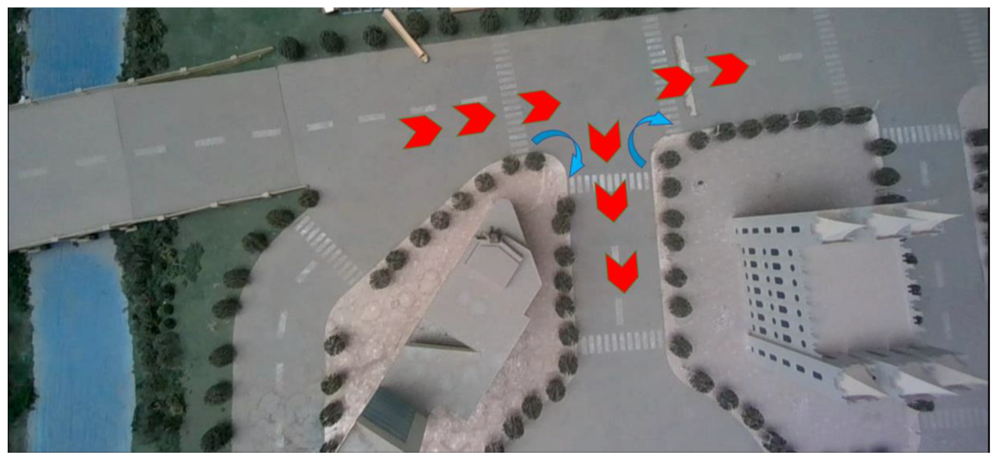
Figure 11 shows the driving route (red arrow) of the car, and Figure 12 shows the position status of the car, according to the driving route. Figure 13a, represents the external view of the car in the experimental scene, where the red arrow is the driving route of the car and the blue arrow is the turning direction of the car. Figure 13b represents the view of the unmanned vehicle when the car is turning. Figure 13c represents the magnified view of the local position of the car at the current time, where the red point in the figure represents the current landmark point seen by the car; the black point is the landmark point seen by the car from a historical perspective, the blue box represents the historical position of the car, and the green box represents the current position of the car. Figure 13d represents the global positioning and mapping of the car, and the green line is the driving trajectory of the car. The positions indicated by the green arrows are the positions of the same position in different views.
In Figure 13, we adopted a tracked unmanned vehicle platform, which has a relatively rich feature detection and a sufficient number of correct matches at sharp turns with a large angle of view that is greater than 90 degrees. The trajectory tracking is complete without tracking loss and pose loss, and the robust operation in a large angle of view fast motion scene is realized. We conducted qualitative experiments on our proposed method in a real scene, verified the effectiveness of SLAM tracking in the case of the car equipped with the SLAM system in a sharp turn at the intersection, and completed the tracking.

5. Conclusions

In this paper, we proposed a pseudoinverse Siamese convolutional neural network of transformation invariance, feature detection, and description for a SLAM system in a complex environment. We combine the excellent advantage of convolutional networks in feature detection and description. The backbone network structure, feature detection subnetwork, and feature description submodule were established based on group features. We adopted a single neural network structure with a feature detection and description, which provided a parameter sharing functionality. In addition, we show that the feature extraction and description network is more robust and reliable to feature detections and descriptions with angle, illumination, and texture; this further proves the distinction of the feature detection and the superior performance of the transformation invariance of description. Meanwhile, we further proposed a visual SLAM system based on the pseudoinverse Siamese network and demonstrated a state-of-the-art performance of this SLAM system in complex environments.

Author Contributions

Conceptualization, Y.X.; methodology, C.Y.; software, Z.Z.; validation, J.Y.; formal analysis, C.Y.; investigation, C.Y.; resources, Q.Z.; data curation, Z.Z.; writing—original draft preparation, C.Y.; writing—review and editing, J.Y.; visualization, Q.Z.; supervision, Y.X.; project administration, Y.X.; funding acquisition, Z.Z. All authors have read and agreed to the published version of the manuscript.

Funding

This research is supported by The Nature Science Foundation of Shaanxi under Grant 2022JQ-653 and The Fundamental Research Funds for the Central Universities, Northwestern Polytechnical University (No. D5000210767).

Institutional Review Board Statement

Not applicable.

Informed Consent Statement

Not applicable.

Data Availability Statement

Associated data will be made available on reasonable request.

Conflicts of Interest

I certify that there is no actual or potential conflict of interest in relation to this article.

References

  1. Mur-Artal, R.; Montiel, J.M.M.; Tardós, J.D. ORB-SLAM: A versa-tile and accurate monocular SLAM system. IEEE Trans. Robot. 2015, 31, 1147–1163. [Google Scholar] [CrossRef] [Green Version]
  2. Mur-Artal, R.; Tardós, J.D. ORB-SLAM2: An Open-Source SLAM System for Monocular, Stereo, and RGB-D Cameras. IEEE Trans. Robot. 2017, 33, 1255–1262. [Google Scholar] [CrossRef] [Green Version]
  3. Campos, C.; Elvira, R.; Rodríguez, J.J.G.; Montiel, J.M.M.; Tardós, J.D. ORB-SLAM3: An Accurate Open-Source Library for Visual, Visual–Inertial, and Multimap SLAM. IEEE Trans. Robot. 2021, 37, 1874–1890. [Google Scholar] [CrossRef]
  4. Rosten, E.; Drummond, T. Machine learning for high-speed corner detection. In European Conference on Computer Vision; Springer: Berlin/Heidelberg, Germany, 2006. [Google Scholar]
  5. Forster, C.; Pizzoli, M.; Scaramuzza, D. SVO: Fast semi-direct monocular visual odometry. In Proceedings of the 2014 IEEE International Conference on Robotics and Automation (ICRA), Hong Kong, China, 31 May–7 June 2014. [Google Scholar]
  6. Klein, G.; Murray, D. Parallel tracking and mapping for small AR workspaces. In Proceedings of the 2007 6th IEEE and ACM International Symposium on Mixed and Augmented Reality, Nara, Japan, 13–16 November 2007. [Google Scholar]
  7. Bay, H.; Tuytelaars, T.; Van Gool, L. SURF: Speeded Up Robust Features. In Computer Vision—ECCV 2006; Leonardis, A., Bischof, H., Pinz, A., Eds.; Springer: Berlin/Heidelberg, Germany, 2006. [Google Scholar]
  8. Labbe, M.; François, M. Online global loop closure detection for large-scale multi-session graph-based SLAM. In Proceedings of the 2014 IEEE/RSJ International Conference on Intelligent Robots and Systems, Chicago, IL, USA, 14–18 September 2014. [Google Scholar]
  9. Rublee, E.; Rabaud, V.; Konolige, K.; Bradski, G. ORB: An efficient alternative to SIFT or SURF. In Proceedings of the 2011 International Conference on Computer Vision, Barcelona, Spain, 6–13 November 2011; IEEE: Piscataway, NJ, USA. [Google Scholar]
  10. Lowe, D.G. Distinctive Image Features from Scale-Invariant Keypoints. Int. J. Comput. Vis. 2004, 60, 91–110. [Google Scholar] [CrossRef]
  11. Tang, J.; Ericson, L.; Folkesson, J.; Jensfelt, P. GCNv2: Efficient correspondence prediction for real-time SLAM. IEEE Robot. Autom. Lett. 2019, 4, 3505–3512. [Google Scholar] [CrossRef] [Green Version]
  12. McCormac, J.; Handa, A.; Davison, A.; Leutenegger, S. Semanticfusion: Dense 3d semantic mapping with convolutional neural networks. In Proceedings of the 2017 IEEE International Conference on Robotics and automation (ICRA), Singapore, 29 May–3 June 2017. [Google Scholar]
  13. Tang, J.; Folkesson, J.; Jensfelt, P. Geometric Correspondence Network for Camera Motion Estimation. IEEE Robot. Autom. Lett. 2018, 3, 1010–1017. [Google Scholar] [CrossRef]
  14. Hou, Y.; Zhang, H.; Zhou, S. Convolutional neural network-based image representation for visual loop closure detection. In Proceedings of the 2015 IEEE International Conference on Information and Automation, Lijiang, China, 8–10 August 2015. [Google Scholar]
  15. Li, G.; Yu, L.; Fei, S. A deep-learning real-time visual SLAM system based on multi-task feature extraction network and self-supervised feature points. Measurement 2020, 168, 108403. [Google Scholar] [CrossRef]
  16. Liu, H.; Zhao, C.; Huang, W.; Shi, W. An end-to-end siamese convolutional neural network for loop closure detection in visual SLAM system. In Proceedings of the 2018 IEEE International Conference on Acoustics, Speech and Signal Processing (ICASSP), Calgary, AB, Canada, 15–20 April 2018. [Google Scholar]
  17. Zhang, J.; Miao, M.; Zhang, H.; Wang, J.; Zhang, J.; Qiu, Z. Siamese reciprocal classification and residual regression for robust object tracking. Digit. Signal Process. 2022, 123, 103451. [Google Scholar] [CrossRef]
  18. Xu, G.; Li, X.; Zhang, X.; Xing, G.; Pan, F. Loop Closure Detection in RGB-D SLAM by Utilizing Siamese ConvNet Features. Appl. Sci. 2021, 12, 62. [Google Scholar] [CrossRef]
  19. DeTone, D.; Malisiewicz, T.; Rabinovich, A. Superpoint: Self-supervised interest point detection and description. In Proceedings of the IEEE Conference on Computer Vision and Pattern Recognition Workshops, Salt Lake City, UT, USA, 18–23 June 2018. [Google Scholar]
  20. Liu, Y.; Shen, Z.; Lin, Z.; Peng, S.; Bao, H.; Zhou, X. Gift: Learning transformation-invariant dense visual descriptors via group cnns. arXiv 2019, arXiv:1911.05932. [Google Scholar]
  21. Yi, K.M.; Trulls, E.; Lepetit, V.; Fua, P. Lift: Learned invariant feature transform. In European Conference on Computer Vision; Springer: Cham, Switzerland, 2016. [Google Scholar]
  22. Zhou, Q.; Sattler, T.; Leal-Taixe, L. Patch2pix: Epipolar-guided pixel-level correspondences. In Proceedings of the IEEE/CVF Conference on Computer Vision and Pattern Recognition, Nashville, TN, USA, 20–25 June 2021. [Google Scholar]
  23. Triggs, B.; McLauchlan, P.F.; Hartley, R.I.; Fitzgibbon, A.W. Bundle adjustment—A modern synthesis. In International Workshop on Vision Algorithms; Springer: Berlin/Heidelberg, Germany, 1999. [Google Scholar]
  24. Bruno, H.M.S.; Colombini, E.L. LIFT-SLAM: A deep-learning feature-based monocular visual SLAM method. Neurocomputing 2021, 455, 97–110. [Google Scholar] [CrossRef]
  25. Lin, H.-Y.; Hsu, J.-L. A Sparse Visual Odometry Technique Based on Pose Adjustment With Keyframe Matching. IEEE Sens. J. 2020, 21, 11810–11821. [Google Scholar] [CrossRef]
  26. Cohen, T.; Welling, M. Group equivariant convolutional networks. In Proceedings of the International Conference on Machine Learning, PMLR, New York, NY, USA, 19–24 June 2016. [Google Scholar]
  27. Lin, T.Y.; RoyChowdhury, A.; Maji, S. Bilinear cnn models for fine-grained visual recognition. In Proceedings of the IEEE International Conference on Computer Vision, Santiago, Chile, 7–13 December 2015. [Google Scholar]
  28. Lin, T.Y.; Maire, M.; Belongie, S.; Hays, J.; Perona, P.; Ramanan, D.; Dollár, P.; Zitnick, C.L. Microsoft coco: Common objects in context. In European Conference on Computer Vision; Springer: Cham, Switzerland, 2014. [Google Scholar]
  29. Kingma, D.P.; Ba, J. Adam: A method for stochastic optimization. arXiv 2014, arXiv:1412.6980. [Google Scholar]
  30. Sturm, J.; Engelhard, N.; Endres, F.; Burgard, W.; Cremers, D. A benchmark for the evaluation of RGB-D SLAM systems. In Proceedings of the 2012 IEEE/RSJ international conference on intelligent robots and systems, Vilamoura-Algarve, Portugal, 7–12 October 2012. [Google Scholar]
  31. Balntas, V.; Lenc, K.; Vedaldi, A.; Mikolajczyk, K. HPatches: A benchmark and evaluation of handcrafted and learned local descriptors. In Proceedings of the IEEE Conference on Computer Vision and Pattern Recognition, Honolulu, HI, USA, 21–26 July 2017. [Google Scholar]
Figure 1. The frame of self-supervised training.
Machines 10 01070 g001
Figure 2. The overall framework of the proposed SLAM system. On the left, the feature detection and description frame architecture mainly includes three modules: backbone, feature detector, and descriptor. The right side is mainly composed of three parts: tracking, local mapping, and mapping.
Machines 10 01070 g002
Figure 3. Proposed pseudoinverse Siamese network structure overview for transformation invariance feature detection and description.
Machines 10 01070 g003
Figure 4. Overview of the Visual SLAM System. The proposed visual SLAM system mainly includes two modules, the tracking module, and the local mapping module.
Machines 10 01070 g004
Figure 5. Feature point detection comparison on viewing angles. Figures (1), (2), (3), (4), and (5) represent images from 5 different viewing angles, respectively.
Machines 10 01070 g005
Figure 6. Feature point matching and comparison of viewing angles. Among them, 1-i (i=2, 3, 4, 5) is the matching between the first and i-th view images.
Machines 10 01070 g006
Figure 7. Feature point matching and comparison on illumination.
Machines 10 01070 g007
Figure 8. Feature point matching and comparison on texture.
Machines 10 01070 g008
Figure 9. Successful matching performance comparison on HPatches dataset.
Machines 10 01070 g009
Figure 10. Visual localization trajectory comparison.
Machines 10 01070 g010
Figure 11. Top view of the running path. The red arrows indicate the traveling direction of the car, and the blue arrows indicate the turning direction of the car.
Machines 10 01070 g011
Figure 12. Illustration of the car in different locations. Images (1), (2), (3), and (4) show the position of the car at different moments, respectively.
Machines 10 01070 g012
Figure 13. A real scene experiment of the SLAM system is proposed. The green arrow points to indicate the location of the turning intersection in different views. The red arrow indicates the direction of travel of the cart.
Machines 10 01070 g013
Table 1. Homography Estimation on Hpatches.
ε = 1ε = 3ε = 5
Ours0.570.850.94
SuperPoint0.540.820.90
ORB0.210.520.69
Table 2. Trajectory absolute error.
DatasetOursORB-SLAM2 [2]GCN-SLAM [11]
fr1/room0.0630.059
fr1/desk0.0540.041
fr1/desk20.0510.0420.091
fr1/floor0.0460.21
fr2/desk0.0500.0060.018
fr2/large_no_loop0.2200.222
fr2/poineer_slam30.0570.042
fr3/long_office_household0.0180.0080.016
fr3/structure_notexture_far0.0100.009
fr3/structure_notexture_near0.014
fr3/structure_texture_far0.0120.0100.012
fr3/structure_texture_near0.0100.0110.012
Publisher’s Note: MDPI stays neutral with regard to jurisdictional claims in published maps and institutional affiliations.