Article

Geochemical Characterization of Iron and Steel Slag and Its Potential to Remove Phosphate and Neutralize Acid

1
U.S. Geological Survey, 954 National Center, Reston, VA 20192, USA
2
U.S. Geological Survey, 5957 Lakeside Boulevard, Indianapolis, IN 46278, USA
*
Author to whom correspondence should be addressed.
Minerals 2019, 9(8), 468; https://doi.org/10.3390/min9080468
Submission received: 17 June 2019 / Revised: 19 July 2019 / Accepted: 22 July 2019 / Published: 31 July 2019
(This article belongs to the Special Issue Metallurgical Slags)

Abstract

:
Iron and steel slags from legacy and modern operations in the Chicago-Gary area of Illinois and Indiana, USA, are predominantly composed of Ca (10–44 wt. % CaO), Fe (0.3–28 wt. % FeO), and Si (10–44 wt. % SiO2), with generally lesser amounts of Al (<1–15 wt. % Al2O3), Mg (2–11 wt. % MgO), and Mn (0.3–9 wt. % MnO). Mineralogy is dominated by Ca ± Mg ± Al silicates, Fe ± Ca oxides, Ca-carbonates, and high-temperature SiO2 phases. Chromium and Mn concentrations in most samples may be environmentally significant based on comparison with generic soil contaminant guidelines. However, simulated weathering tests suggest these elements are present in generally insoluble phases making their use in water treatment applications possible; however, the generation of high pH and alkaline solutions may be an issue. As for possible water treatment applications, batch and flow-through experiments document effective removal of phosphate from synthetic solutions for nearly all slag samples. Air-cooled fine fractions (<10 mm) of modern slag were most effective; other types, including modern granulated, modern air-cooled coarse fractions (>10 mm), and legacy slag removed phosphate, but to a lesser degree. An additional water treatment application is the use of slag to neutralize acidic waters. Most slag samples are extremely alkaline and have high net neutralization potentials (NNP) (400–830 kg CaCO3/t), with the highest approximately equivalent to 80% of the neutralization potential of calcite. Overall, phosphate removal capacity and NNP correlate positively with total Ca content and the dissolution of Ca minerals facilitates secondary Ca phosphate formation and consumes acid during hydrolysis. Utilizing locally available slag to treat waste or agricultural waters in this region may be a higher value alternative than use in construction, potentially offsetting restoration costs to degraded legacy areas and decreasing steel manufacturers’ current waste footprint.

1. Introduction

Ferrous slags are byproducts generated after smelting iron ore in a blast furnace to make pig iron (referred to as iron or blast furnace slag) or after smelting pig iron and scrap metal most commonly in a Basic Oxygen Furnace (BOF) or Electric Arc Furnace (referred to as steel slag). Slag can either be left to cool under atmospheric conditions (air-cooled) or under expedited rates with air or water to impart certain qualities, such as a high porosity or a glassy texture [1]. In the U.S. alone, it is estimated that 15 to 20 million tons of ferrous slag are produced annually; it is considered a domestic commodity for its value in various applications [2]. The most common use of ferrous slag is in construction. The hard and dense nature of air-cooled slag makes it suitable for its primary use as aggregates in concrete, asphalt paving, fill and road bases. Almost all granulated blast furnace slag (e.g., cooled with high-pressure sprays of water) is used in concrete mixes or in blended cements as a partial substitute for Portland cement [2]. In addition to construction use, ferrous slag also has various environmental applications. Previous studies have documented the effectiveness of ferrous slag as a sorbent to remove nutrients and trace elements from solution to control unwanted anthropogenic emissions, as summarized by Piatak et al. [1]. Numerous studies have documented the effectiveness of using steelmaking slag to remove phosphorus (P) from wastewaters and agricultural runoff [3,4,5,6,7,8,9,10,11,12,13,14,15]. Ferrous slag has also been shown to be an effective acid-neutralizing agent with applications in the treatment of acid-mine drainage from coal and base-metal operations [16,17,18,19,20,21,22].
Steelmaking cities in the USA along the Great Lakes that include Chicago, Cleveland, and Detroit have been making steel for more than a century. Along these coastlines, slag infills lake-shore wetlands and provides fill base for many industrial sites. The ferrous slag-fill areas have been shown to generate hyperalkaline drainage. In the Chicago-Gary area of Illinois and Indiana, USA, surface water and groundwaters near ferrous slag have been documented with pH values of up to 12 [23,24,25,26]. Additionally, regional eutrophication and local acidification are concurrent problems in waterways entering the Great Lakes. Phosphorus in runoff and subsurface drainage from agricultural and urban lands is suspected as a key contributor to eutrophication leading to harmful algal blooms—an emerging environmental concern—and associated degradation of habitat in nearshore areas and waterways [27]. In addition, acidic waters from coal and base-metal mining are a continuing issue for mitigation of legacy and more recently mined lands [28]. This research aims to characterize the chemistry and mineralogy of steelmaking slag from the Chicago-Gary area from both legacy sites (legacy slag) and current production by steelmaking facilities (modern slag). We use laboratory bench-scale tests to determine the various slag types’ abilities to remove phosphate from solution, which are relevant to the mitigation of nutrient-rich waters. In addition, we determine the neutralization potentials of the various slag types, which is applicable to mitigating acidic waste streams. Preliminary results were presented in Piatak et al. [29].

2. Materials and Methods

2.1. Site Description and Sampling Strategy

Ferrous slag was collected from several legacy sites in the Chicago-Gary area of Illinois and Indiana near Lake Michigan where slag had been stockpiled or used as fill. At most legacy sites, 30 to 50 fist-size individual samples were composited from various locations to obtain a generally representative sample. At one legacy site, ILSS2, an approximately 20 kg grab sample was collected. U.S. Steel Corporation and Arcelor Mittal S.A. also provided samples of various types of slag from their operating steelmaking facilities at Gary Works and Indiana Harbor, respectively. Table 1 includes a list of samples; the composites at each site encompassed a representative area of each slag deposit.
Nearly all samples in this study were air-cooled and vesicular or massive in texture. Samples were generally dark in color, commonly black, brown, or gray. At the operating steelmaking facilities, the air-cooled slag is generally sorted by size with coarser material sold for use in erosion control, railroad beds, or driveways. The smaller size fraction, generally less than 9.5 mm in diameter referred to as C-fines, is marketed for asphalt or concrete road bases, unpaved driveways, or walking/biking paths. Samples of the finer sorted slag or C-fines (AMFeC, AMSteelC, and USSSteelC) and coarser fractions (USSFeair, USSSteelB_3/8, and USSSteelB_3/8-4) were included in this study and the size of the material and type of furnace that generated the slag are given in Table 1. The C-fine samples were sieved to less than 9.5 mm and each contained a small fraction of material greater than this size (1.5 to 4 wt. %) which was not included for analyses. Legacy sample ILSS2 was also C-fines sieved to less than 9.5 mm; 2 wt. % in this sample was greater than 9.5 mm and not included in analyses. The composites (30–50 subsamples) of air-cooled slag from legacy sites were crushed to <9.5 mm to be consistent with the size of the C-fine material (Table 1). The only sample that was not air-cooled is USSFegran, which was a granulated iron slag from U.S. Steel Corporation and was composed of <9.5 mm sand-sized glassy fragments. The material as described above was used for mineralogical and chemical characterization, acid-base accounting, and for the batch phosphate removal experiments. Slag material used in the phosphate removal column experiments is described below.

2.2. Mineralogical and Geochemical Investigations

The mineralogy of the bulk slag samples and the secondary phases on reacted surfaces after the phosphate removal experiments was evaluated by optical microscopy, powder X-ray diffraction (XRD), and scanning electron microscopy (SEM) in U.S. Geological Survey (USGS) laboratories in Reston, Virginia (USA). For quantitative mineralogy estimates by XRD analysis, splits of samples were pulverized in alcohol in a micronizing mill (Style number 232, McCrone Microscopes and Accessories, West Mont, IL, USA). Pulverized samples placed into back-loaded aluminum holders were analyzed by XRD using a PANalytical X’Pert PRO automated powder diffractometer (PANalytical Inc., Westborough, MA, USA) with CuKα or CoKα radiation. Identification and quantification of phases in bulk samples were conducted on patterns of unspiked samples and spiked samples with 20 wt. % crystalline α-Al2O3 (i.e., corundum) using a Rietveld procedure (X’Pert HighScore Plus software, version 4.7, PANalytical Inc., Almelo, Netherlands) and standard reference patterns that include structural data [30]. Secondary phases were prepared as smear mounts. These samples were analyzed and phases were identified as described previously. The accuracy of the quantitative results is on the order of ±10 wt. % of the amount present based on prepared mixtures of minerals and glass. Bulk samples prepared as polished thin sections and reaction products prepared on carbon tape were examined either using a JEOL JSM-840 SEM (JEOL Ltd., Tokyo, Japan) or a Hitachi SU5000 variable pressure field-emission SEM (Hitachi, Tokyo, Japan) equipped with an X-ray energy-dispersive system (EDS). SEM-EDS spectra were collected using an accelerating voltage of 15 kV, and a specimen current of 1 to 20 nA.
The major elemental composition of slag was determined using wavelength dispersive X-ray fluorescence spectroscopy (WDXRF) following fusion by a mixture of LiBO2 and LiB4O7; the WDXRF analysis procedure includes loss on ignition (LOI) or percentage of mass lost determined after heating to 925 °C. LOI is used as an estimate of the content of combined organic, carbonate, water, and other volatile substances. Minor and trace element chemistry was determined by inductively coupled plasma-atomic emission spectrometry (ICP-AES) and inductively coupled plasma-mass spectrometry (ICP-MS) following acid-digestion using a mixture of HCl-HNO3-HClO4-HF. The total carbon and total sulfur contents were measured by combustion followed by infrared detection on Carbon and Sulfur Determinator LECO CS844(LECO Corp., St. Joseph, MI, USA). Carbonate carbon in the bulk rock samples was determined as carbon dioxide by coulometric titration. The reproducibility for most elements based on the analysis of a replicate sample is approximately ±15%; for WDXRF, the acceptable reproducibility was no greater than 5%. Analytical results were deemed acceptable if the obtained value was within ±15% (or ±5% for WDXRF) of the expected value of standard reference materials certified by the USGS. These analyses were conducted by Geneva as Société Générale (SGS) Laboratories (Toronto, ON, Canada) and AGAT Laboratories (Mississauga, ON, Canada) through contract with the USGS. The methods used for analysis are also detailed in [31].
Acid base accounting (ABA) was determined by Maxxam Analytics (Burnaby, BC, Canada) using the modified acid base accounting (ABA) technique [32] to quantify neutralization and acid-generation potentials. The specific surface area was measured by the Brunauer, Emmett, and Teller (BET) method by Particle Technology Labs (Downers Grove, IL, USA). The methods used for analysis are detailed in [31].
The synthetic precipitation leaching procedure (SPLP) (U.S. Environmental Protection Agency (USEPA) Method 1312); [33] was used on splits of samples in USGS laboratories. Samples were crushed and sieved to a diameter of less than 2 mm according to the Method 1312 protocol. Fifty grams of crushed and/or sieved samples were combined with one liter of a solution that approximates Western United States precipitation. The solution was made by combining a mixture of sulfuric acid and nitric acid with deionized water adjusted to pH 5.00 ± 0.05 [33]. The sample and solution mixtures were agitated in a rotary extractor apparatus for 18 h. Specific conductance and pH were measured with an Orion Versa Star benchtop meter (Thermo Scientific, Waltham, MA, USA). Alkalinity was determined on filtered (0.45 µm) splits by adding phenolphthalein and bromocresol green-methyl red pH indicators to a known volume of sample and titrating with standardized H2SO4. Filtered (0.45 µm) acidified splits were analyzed for dissolved cations by ICP-MS and ICP-AES, and filtered unacidified splits for dissolved anions (sulfate and chloride) by ion chromatography (IC) in USGS laboratories in Denver, Colorado, USA. Reproducibility for most elements based on the analysis of a replicate sample is generally better than ±10%. The accuracy of the analyses was typically within one standard deviation for major cations (ICP-AES), trace elements (ICP-MS), and anions (IC) for standard reference waters certified by the USGS.

2.3. Phosphate Removal Experiments

Batch and column bench-scale experiments were conducted to determine phosphate removal capacities of ferrous slag. Static batch experiments using end-over-end rotation and a solution to a solid ratio of 1:20 were performed on slags for size fractions indicated in Table 1 and on samples of commercial-grade pulverized agricultural limestone and quartz sand (both sieved to <2.0 mm), both for comparison purposes. Methods were modified from batch tests performed by Barca et al. [9]. Leaching solutions were prepared using deionized water and reagent-grade monopotassium phosphate (KH2PO4). The first set of batch experiments using 10 mg P/L were determined to be at a pseudo steady state based on pH after 4 days of reaction. For a subset of slag samples, the concentration of the initial phosphate leaching solution was incrementally increased (approximate concentrations of 50, 100, 250, 500, and 1000 mg P/L) until a maximum phosphate removal capacity was obtained for all tested samples. These experiments were reacted for 7 days; end-over-end rotation for approximately 12 h a day for 5 days, and then allowed to settle for 2 days. The limestone and sand were tested at high and low phosphate concentrations, respectively.
For the reacted solutions, pH and specific conductance were measured with an Orion Versa Star benchtop meter. Total dissolved phosphate concentrations of all samples and the acid hydrolysable phosphate for some samples were measured spectrographically on filtered splits (0.45 µm) using the ascorbic acid method; phosphate present in the samples was determined to be reactive phosphate (orthophosphate). Alkalinity, and dissolved cation and anion concentrations were determined on filtered (0.45 µm) splits of reacted solutions as described in Section 2.2 for the SPLP leachates. In addition, solid material that was deposited on the filters during filtration was collected for XRD analysis to gain insight into secondary phases that may have formed during the experiments. Secondary phases on filters, as well as in residual solid material, were characterized using SEM. XRD and SEM methods are described above in Section 2.2.
The experimental setup for the column experiments consisted of a reservoir with influent, Ismatec peristaltic pumps, clear acrylic columns, flow-through cells, electrodes, a meter, and beakers (Figure 1). Two slag samples (AMFeC and ILSS5) were further crushed to <4.75 mm to ensure adequate flow within columns (inner diameters of 5 cm, length of 23.5 cm, volume 510.5 cm3). Samples were also sieved to >0.5 mm to remove fines to avoid clogging. Splits of these sieved samples were also characterized for mineralogy and chemistry based on the methods described above in Section 2.2. The column was packed with approximately 100 g splits of slag funneled into the column in a circular direction to create non-stratified layers. Both ends of the column were sealed with Viton O-rings. Nitex (next to the sample) and Porous Polyeth Sheet (35 μm) screens were placed at the bottom and top of column endplates to prevent flushing of solids from the column. Four columns were packed, two with the modern slag (columns A and B) and two with the legacy slag (columns C and D). Columns B and C were used for the tracer tests and columns A and D were used for the phosphate removal experiments.
The influent solution for the phosphate removal experiments contained approximately 115 mg P/L and was prepared using tap water and reagent-grade KH2PO4. Tap water was used because it contains a range of constituents that are present in natural waters, except for residual chlorine, which may inhibit potential biotic removal of P. The first batch of influent solution (TapP, average 115 mg P/L) was used for approximately the first 400 pore volumes flushed through the column, and the second batch (TapP2, average 117 mg P/L) was used for the remainder of the experiment. The concentration of phosphate in the influent was measured weekly and splits were taken once a month for full chemical analysis (see below) to verify a consistent influent composition throughout the experiment.
The phosphate removal columns were slowly saturated from the bottom to the top. Once saturated, the porosity was determined gravimetrically and then flow adjusted using a peristaltic pump to reach a void hydraulic retention time (HRTv) of approximately 8 h for continuous flow. The porosity for the column containing the legacy slag (ILSS5, column A) was 55% and the porosity for the column containing the modern slag (AMFeC, column D) was 47%. Pump speed was adjusted throughout the experiment based on the volume of effluent (continuously measured) and porosity to target a HRTv of 8 h. For the duration of the experiment, the calculated HRTv ranged from 7.5 to 9.6 h and averaged 8.1 h for the column containing ILSS5 slag (column A) and ranged from 6.9 to 8.2 h and averaged 7.9 h for the column containing AMFeC slag (column D).
During the experiment, the effluent pH was measured hourly using an air-tight flow through the cell before the solution was exposed to the atmosphere (“air-free pH”) (Figure 1). The effluent was then discharged into an open-to-the-atmosphere cell where specific conductance was measured hourly before the effluent overflow was collected in a large glass beaker; the total discharge volume was monitored over time. The “air-exposed pH” of the overflow was also measured, after exposure to the atmosphere. The experiments were terminated after approximately 760 (legacy slag-filled column) and approximately 790 (modern slag-filled column) pore volumes had passed through the columns (or nearly 9 months duration). The columns were disassembled and the mineralogy of secondary coatings and precipitates was determined using XRD and SEM.
During the phosphate removal column experiment, pore volumes of effluent were collected, and the phosphate concentration was measured on filtered splits (0.45 µm) by spectrophotometry using the ascorbic acid method. Reacted solutions from experiments were filtered (0.45 µm) and alkalinity and dissolved anion concentrations were determined weekly, and more frequently at the beginning of the experiment, as described in Section 2.2 for the SPLP leachates. Dissolved cations were determined by ICP-MS and ICP-AES by AGAT Laboratories (Mississauga, ON, Canada) through a contract with USGS. Geochemical modeling was performed using PHREEQC v.3.3 (USGS, Lakewood, CO, USA) with the minteq.v4 database (USEPA, Athens, GA, USA).
Conservative tracer tests using a NaCl solution were conducted to assess the hydraulic properties of the experimental media. Based on gravimetric measurements, the porosities (includes isolated and dead-end pores) of the saturated columns were 46% for column B (ILSS5) and 43% for column C (AMFeC). Column flow and solute transport parameters were determined by modeling the leading edges of the breakthrough curves using the nonlinear least squares optimization software CXTFIT 2.1 (U.S. Department of Agriculture, Riverside, CA, USA) [34,35]. Based on four tests, the average dispersivity for column B (ILSS5) was 1.1 cm and the average dispersivity for column C (AMFeC) was 1.8 cm. For additional details, see Hoppe et al. [31].

3. Results

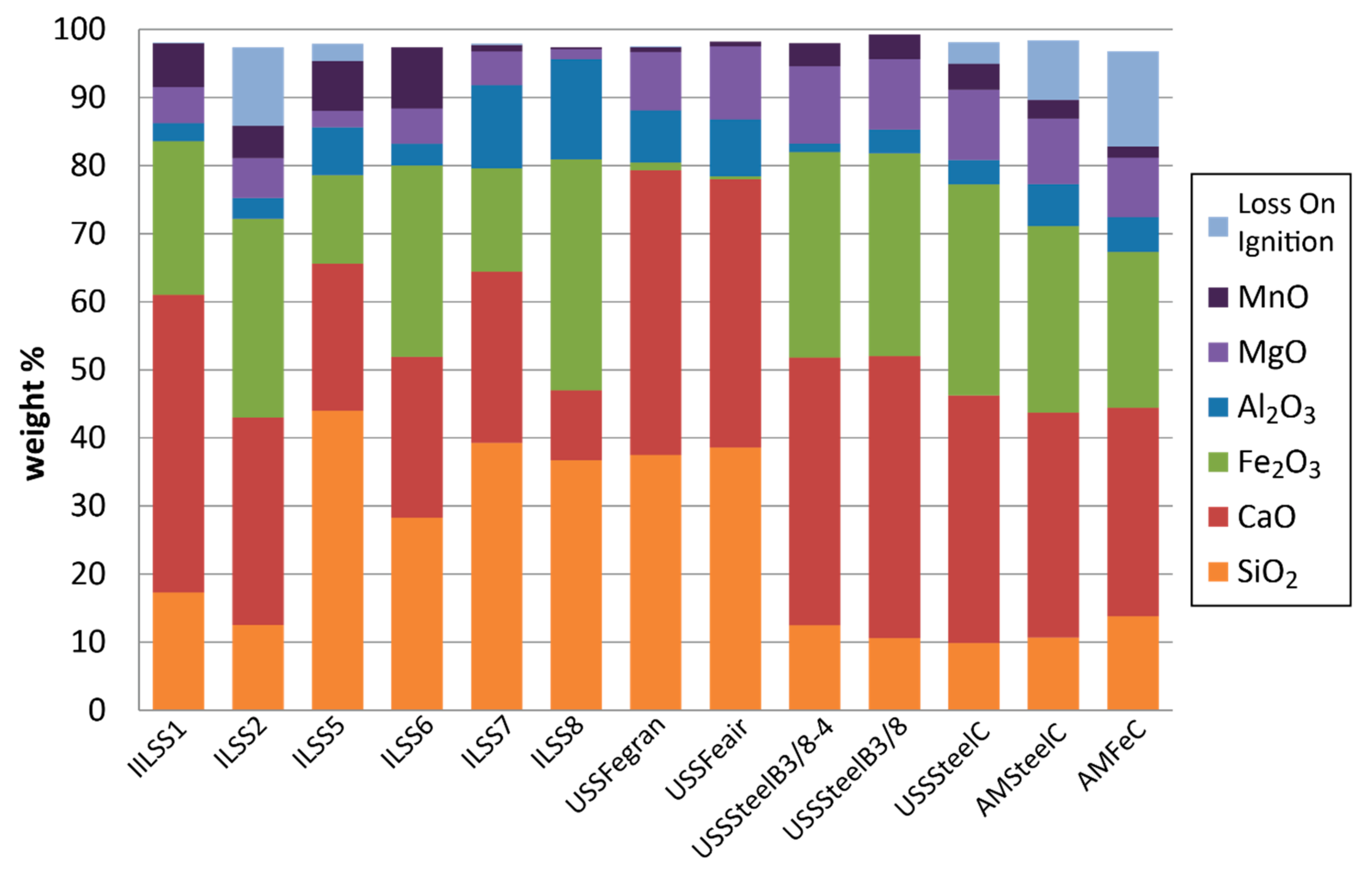
3.1. Geochemical Characteristics
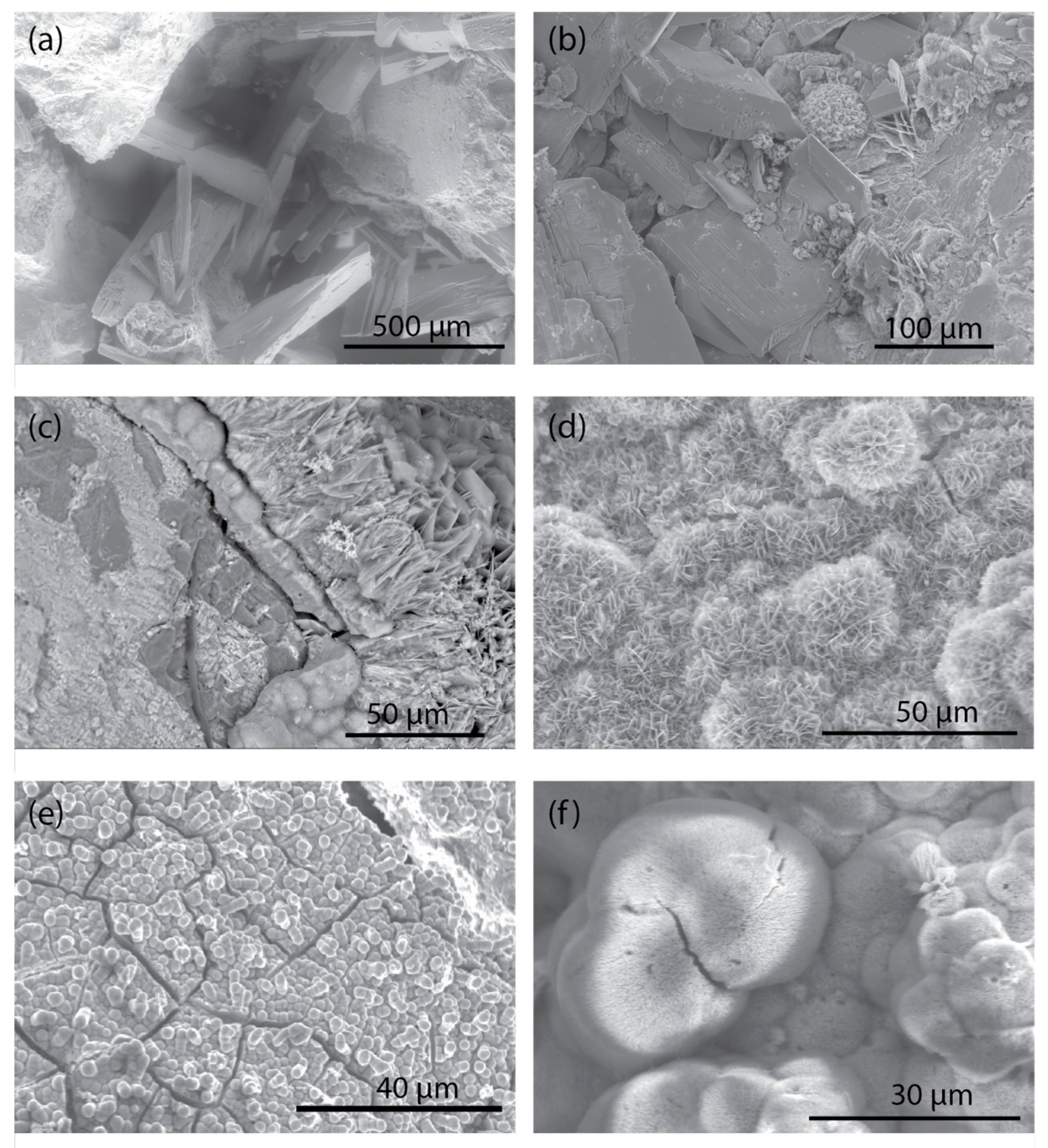
The major element chemistry of the modern and legacy slags (n = 13) is illustrated in Figure 2 and full chemical analyses are provided in Hoppe et al. [31]. Total Fe is reported as Fe2O3 or Fe depending on the analytical technique used in Hoppe et al. [31]. WDXRF reports the presence of Fe2O3 and does not imply a speciation for Fe (i.e., Fe3+). Based on the mineralogy (see section below) Fe was present as both Fe2+ and Fe3+ in most samples, however, Fe2+ likely dominates.
The most abundant elements found in the slag were Al, Ca, Fe, Mg, Mn, and Si (Figure 2). The iron slags from Gary Works, one air-cooled (USSFeair), the other granulated (USSFegran), had similar compositions with the following approximate concentrations: 40 wt % CaO, 38 wt. % SiO2, 10 wt. % MgO, 8 wt. % Al2O3, and 1 wt. % Fe2O3 and MnO; the Al concentrations in these samples were the highest and the Fe concentrations were the lowest among the modern samples (Figure 2). The modern steel slags and the iron C-fine slag from Indiana Harbor (AMFeC) had similar chemical compositions with the following concentration ranges: 31–41 wt. % CaO, 23–31 wt. % Fe2O3, 9–11 wt. % MgO, 1–6 wt. % Al2O3, 2–4 wt. % SiO2, 2–4 wt. % MnO. These samples had markedly lower concentrations of Si compared to most other samples. The major element compositions of the slags from the legacy sites were variable but the same elements generally dominated compared with the modern samples. However, the modern iron and steel slags generally had higher concentrations of Ca and Mg than slag from the legacy sites (Figure 2). Another element that occurred in concentrations of up to several weight percent was C; total C as well as carbonate C are reported in Hoppe et al. [31]. Concentrations of total C reached up to nearly 5 wt. % in the iron slag from Indiana Harbor (AMFeC). The steel slag (AMSteelC) and slag from two legacy sites (ILSS2, ILSS5) contained slightly less C with concentrations that ranged from 1.5 to 2.7 wt. % C. Carbonate C was highest in ILSS2 at 2.3 wt. % C, and accounted for the majority of the C in the sample. In contrast, nearly two-thirds of the C in AMFeC and AMSteelC was determined to not be in carbonate from. All other samples contained less than 1 wt. % C. Sulfur was generally low in these samples, with the highest concentrations reaching 1 wt. % S in the Gary Works iron slags (USSFegan, USSFeair) (Table 2). Phosphate was present in comparable concentrations to S with a maximum concentration of 1.4 wt. % P2O5 for a legacy site (ILSS6). Other major elements, such as K and Na, were present in low concentrations, at 1 wt. % oxide or less. For concentrations of major and trace elements, see Hoppe et al. [31].
Several minor or trace elements were found in minor but significant amounts, on the order of hundreds to thousands of mg/kg. For example, Cr concentrations ranged from 0.01 wt. % up to 0.8 wt. % Cr, with the highest concentrations for slag collected from two legacy sites (ILSS2 and ILSS6). Titanium was also present and ranges from 0.2 to 0.6 wt. %. The following elements were generally found in concentrations in the hundreds of mg/kg: Ba (41 to 1430 mg/kg), Pb (0.5 to 570 mg/kg), Sr (117 to 364 mg/kg), and V (56 to 1410 mg/kg). The concentrations of other elements were generally less than 100 mg/kg [31].
The specific surface area for the size fractions given in Table 1 are reported in Hoppe et al. [31]. The lowest specific surface areas were for coarse air-cooled slags (USSFeair, USSteelSteelB_3/8, USSSteelB_3/8-4) with values that ranged from 0.23 to 0.97 m2/g. These samples were coarser size fractions compared to the other samples. Other samples ranged from 1.07 to 7.07 m2/g, except for ILSS2, the legacy C-fines, which had a specific surface area of 18.52 m2/g.
As previously mentioned, splits of the two samples (ILSS5 and AMFeC) that were used in the column experiments were further crushed and sieved to ensure adequate flow in the columns. The major element chemistries of the <9.5 mm split and the <0.5 mm split were compared to the split used in the columns (<4.75 mm and >0.5 mm) to determine if additional crushing and sieving concentrated any elements. Considering a reproductivity and accuracy of ±5% to 15% each, the variations in concentration of most major elements appear to be within analytical error of the method or close to it. One exception is LOI for both samples, which was two to three times higher in the bulk compared to the <4.75 mm and >0.5 mm fraction. In addition, C and carbonate C were lower in the <4.75 mm and >0.5 mm fraction compared to the bulk by up to 30% in ILSS5 and up to 70% in AMFeC [31]. The minor and trace element concentrations in the crushed and sieved size fractions compared to the bulk were more variable than those for the major elements. However, most of these elements were not consistently enriched or depleted in a specific size fraction for both samples (ILSS5 and AMFeC). Overall, the chemical similarities among the splits suggest the material used in the column experiments was generally representative of the bulk samples. The major element chemistry for the two samples used in the column experiments is shown in Table 3.

3.2. Mineralogy

A wide variety of minerals were identified in the modern and legacy slags. For this discussion, crystalline phases found in the slag, although anthropogenic in origin, are referred to as minerals. Estimates of the mineral abundances are grouped as follows: major, >10 wt. %; minor, 1–10 wt. %; and trace, <1 wt. %. The modern slags from steelmaking furnaces (Table 1) contain major to minor amounts of wüstite (FeO), brownmillerite–srebrodolskite (Ca2(Al,Fe)2O5 to Ca2Fe2O5), larnite (Ca2SiO4) (all samples except AMSteelC), spinel, likely magnetite (Fe3O4) (all sample except USSSteelB_3/8-4), and Ca-carbonate minerals (CaCO3) including calcite, vaterite, and aragonite. Graphite is also present in major to trace amounts in most samples; the samples with the highest abundance of graphite also have the highest non-carbonate C concentrations based on bulk chemistry (Section 3.1). Other minerals found in generally less abundance in the modern steel slags include lime (CaO), quartz (SiO2), hatrurite (Ca3SiO5), melilite group (åkermanite–gehlenite, Ca2Mg(Si2O7) to Ca2Al(AlSiO7)), mayenite (Ca12Al14O33), as well as trace amounts of ettringite (Ca6Al2(SO4)3(OH)12∙26H2O) and Fe metal. Glass is likely ubiquitous and estimates of amorphous content based on Rietveld analysis of XRD patterns of Al2O3-spiked samples for the modern steelmaking slags are between 26 to 65 wt. % (amorphous or glass content was not included in the ranking of major, minor, and trace mineral abundances discussed above). The mineralogy of the C-fine sample from the iron blast furnace from Indiana Harbor (AMFeC) was very similar to the modern steel slags in mineralogy and in bulk chemical composition (see Figure 2). As for the other modern iron slags, the air-cooled sample (USSFeair) is predominantly composed of melilite with lesser amounts of pyroxene (augite (Ca,Na)(Mg,Fe,Al,Ti)(Si,Al)2O6) based on XRD), spinel group (predominantly magnesioferrite–magnetite, MgFe2O4 to Fe3O4), calcite, and glass and the granulated iron slag (USSFegran) is nearly all glass (estimated to be 91 wt. %) with minor to trace amounts of calcite, monohydrocalcite (CaCO3∙H2O), mullite (Al6Si2O13), and spinel. According to Piatak et al. [1], the most commonly reported phases for ferrous slag worldwide are SiO2 minerals, olivines ((Mg,Fe)2SiO4), melilite, merwinite (Ca3Mg(SiO4)2), brownmillerite–srebrodolskite, monooxides (Ca and Fe, most commonly), spinel, and carbonates. These phases were all identified in iron and steel slags from the Chicago-Gary area. A mineral that may be unique to steel slags, and not reported in iron slags, is hatrurite based on slags from this study and those reported in Piatak et al. [1].
The mineralogy of the slag from the legacy sites included minerals that were not identified in the modern slags potentially due to weathering of primary phases and contamination by non-slag particles. The composites from the legacy sites targeted slag-like materials but, at several locations, foreign materials such as bricks or other foundry materials, were commingled with the slag; these materials were avoided during sample collection. There is overlap in the mineralogy between the legacy and modern materials. For example, samples ILSS1, ILLSS2, and ILSS6 all contained major wüstite, and larnite, and major to minor Ca carbonates and åkermanite–gehlenite. Other phases present in these samples in major to minor amounts included: spinel group, brownmillerite–srebrodolskite, and pyroxene. Based on XRD, the composition of the pyroxenes was diopside–hedenbergite (CaMgSi2O6 to CaFeSi2O6) and enstatite–ferrosilite (Mg2Si2O6 to Fe2Si2O6). ILSS1 contained hatrurite, which may be unique to steel slags; it also contained lime which was present in two modern steel slags. In general, the mineralogy of ILSS1 and ILSS2 were comparable to the modern slags. Whereas, ILSS6 contained tridymite, cristobalite, and monticellite (CaMgSiO4), none of those minerals were found in ILSS1, ILSS2 or the modern slag samples. The ILSS6 composition indicates generation under conditions different to those of the modern facilities or that the site contains multiple types/generations of slag. ILSS6 also contained hematite, a likely secondary weathering product. The other three legacy slag samples, ILSS5, ILSS7 and ILSS8, also contained a suite of mineralogy that substantially deviated from the modern slag examined in this study. All three samples did contain major åkermanite–gehlenite, as reported in several modern slags, but, unlike the modern slags, these samples did not contain wüstite. ILSS7 and ILSS8 contained hematite, a potential weathering product after primary Fe-bearing minerals such as wüstite, and feldspars (albite–anorthite, NaAlSi3O8 to CaAl2Si2O8) and ILSS5 contained major cristobalite; none of these minerals were found in the modern slag samples. ILSS5 also contained minor Ca carbonates (calcite, vaterite, and dolomite), quartz, olivine, monticellite, pseudowollastonite (CaSiO3), merwinite, and pyroxene and trace spinel. ILSS7 and ILSS8 contained major spinel, major to minor hematite, pyroxene (ILSS8 only), and minor calcite (ILSS7 only), graphite and quartz. Similar to ILSS6, based on the somewhat complex mineralogy, samples ILSS5, ILSS7, and ILSS8, may be a mix of various types and generations of slag, weathering products, or contain non-slag materials. As with the modern slags, glass was likely ubiquitous in the legacy samples, and, based on XRD analysis, reached up to approximately 50 wt. % (amorphous not included in abundances previously discussed)
The mineralogy of the size-fractions (<4.75 mm and >0.5 mm) of ILSS5 and AMFeC used in the phosphate removal column experiments was similar to the mineralogy of the bulk samples discussed above. The difference in the abundances of minerals in ILSS5 were generally within the error of the Rietveld-method for mineral quantification. In contrast, the mineral abundances for the size fraction of AMFeC used for the column experiment compared to its bulk sample were more variable such that the size fraction had substantially more wüstite, srebrodolskite, and larnite and less graphite, calcite, and gehlenite–åkermanite.

3.3. Synthetic Precipitation Leaching Procedure

The USEPA Method 1312 or Synthetic Precipitation Leaching Procedure (SPLP) was conducted on the slag samples to mimic leaching of contaminants from weathering. The leaching solution, slightly acidified deionized water, simulates interaction with acidic rainwater. The results of the SPLP tests are given in Hoppe et al. [31]. The composition of the SPLP leachates from all slag samples were highly alkaline with pH values ranging from 9.7 to 12.3, the lowest pH was from a legacy site (ILSS8), whereas the highest pH was from modern iron slag (AMFeC). Alkalinity was positively associated with pH in the SPLP leachates and ranged from as low as 15 mg CaCO3/L in ILSS8 to over 1000 mg CaCO3 in AMFeC. Hardness, with values ranging from 27 to 1340 mg CaCO3/L, was overwhelmingly dominated by Ca, and was positively associated with alkalinity and pH. Modern iron and steel slag samples generally had SPLP leachates with higher pH, alkalinity, and hardness compared to the slag from the legacy sites, except for the iron granulated slag (USSFegran) from Gary Works. The SPLP leachate chemistries were consistent with groundwater sampled from slag-affected aquifers in the Chicago-Gary area. Bayless et al. [23,24], Roadcap et al. [25], and Gahala et al. [26] each independently reported pH values reaching over 12, alkalinity reaching over 900 mg/L CaCO3, and hardness reaching over 500 mg/L CaCO3 for slag-affected groundwaters from the Chicago-Gary area.
Several elements occurred in the SPLP leachates in notable concentrations. Aluminum concentrations were as low as 67 µg/L in SPLP leachate from the iron granulated slag (USSFegran) and as high as 17,200 µg/L in leachate from a steel slag sample (USSSteelB3/8). Aluminum concentrations in SPLP leachates from other samples ranged from 150 to 5120 µg/L. In addition to Al, Ba was leached in amounts as high as 145 µg/L, Fe as high as 661 µg/L, K as high as 4.1 mg/L, Mg as high as 2.57 mg/L, Mn as high as 58.9 µg/L, Na as high as 8.2 mg/L, SiO2 as high as 34.3 mg/L, Sr as high as 324 µg/L, and Zn as high as 75 µg/L. Several elements were leached above the detection limit only rarely and included Cr up to 56 µg/L, Mo up to 32 µg/L, and V up to 73.1 µg/L [31]. Anions were also determined in leachates and reached the following concentrations: 8.4 mg/L Cl, 5.3 mg/L F, 1.3 mg/L NO3, and 48.6 mg/L SO4. The least abundant anion was NO3, and, in general, SO4 was the most abundant anion. Other elements were usually present at concentrations near the detection limit [31].

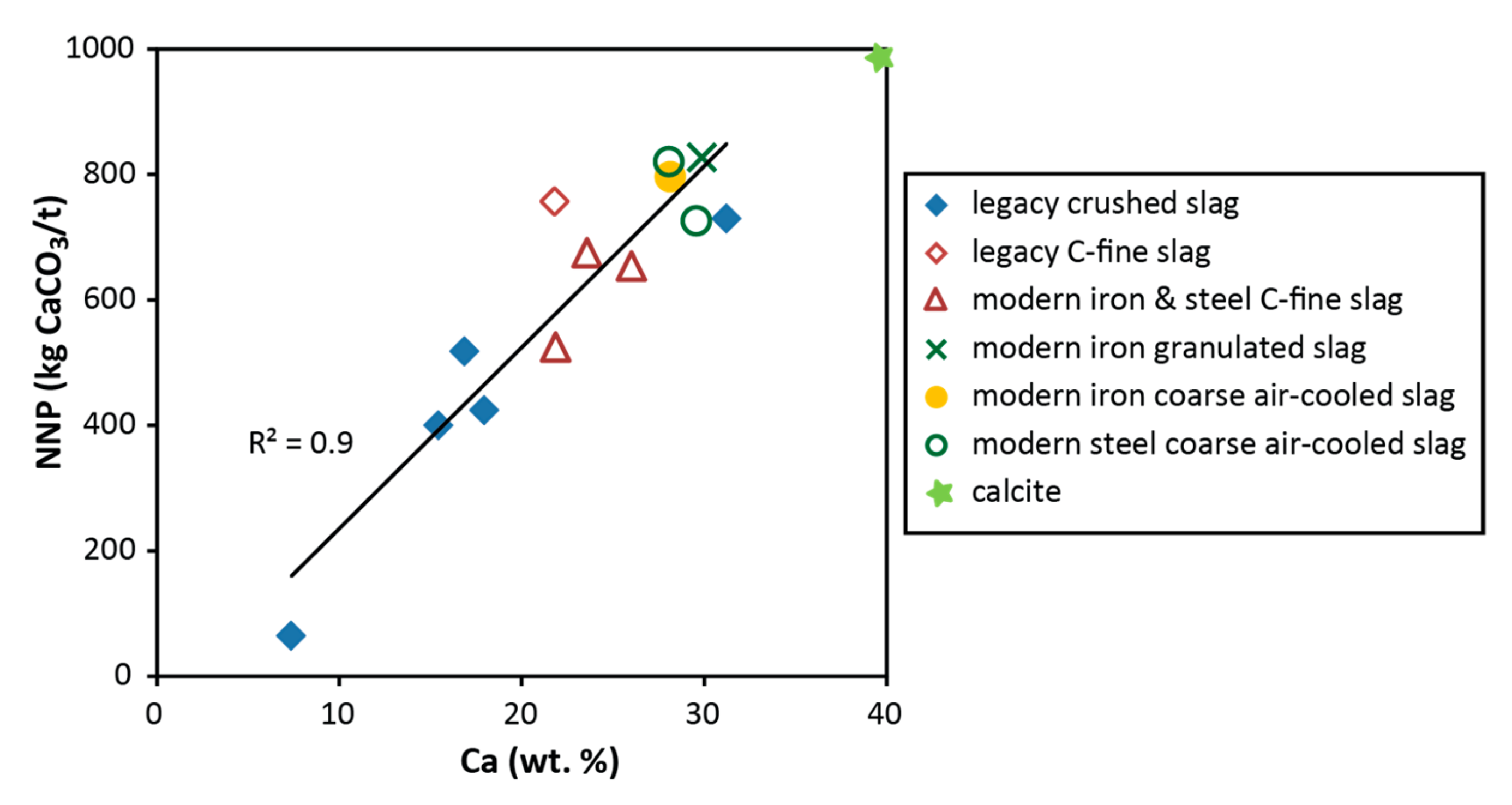
3.4. Neutralization Potential

Acid-base accounting (ABA) is a commonly used static test procedure used to assess the acid-producing (AP) and acid-neutralizing potential (NP) of a material. ABA results include a measurement of paste pH, AP based on sulfide S assumed to be present as pyrite, NP measured by reacting the sample with acid and then back-titrating with base, net-neutralization potential (NNP) calculated from the different of NP and AP, and neutralization potential ratio (NPR) calculated as a ratio of NP to AP. To determine an AP value, each mole of sulfide S, assumed to be present as pyrite, produces two moles of acid and is neutralized by one mole of CaCO3. As a result, the molar ratio of S to CaCO3 is 1:1, such that the weight ratio is 100 g CaCO3/1 mole CaCO3:32 g S/1 mole S, based on the molecular weights of CaCO3 and S. This can also be expressed as 31.25‰ CaCO3 per %S. ABA results are given in Table 2 and Hoppe et al. [31].
The concentration of total S (0.04 to 1.08 wt. % S) and sulfide S (<0.02 to 1.04 wt. % S) were generally low in these samples, with the highest concentrations for both found in the iron slags from Gary Works (approximately 1 wt. % total S and sulfide S). For slag from the legacy sites, the total S is 0.56 wt. % or less, with total S dominated by sulfide S in most samples. The modern steel slags had relatively low S concentrations (<0.22 wt. %) and contained both sulfide S and sulfate S. Based on the sulfide S concentrations, these slags are predicted to generate acid requiring, at most, an equivalent of 32.5 kg CaCO3/t for neutralization, or approximately 3.25 wt. % CaCO3 (Table 2).
In contrast to generally low AP values, the iron and steel slags produced basic paste pH values (pH 10 to 12.5) and most had high NP values of 410 to 860 kg CaCO3/t. Most NNP values ranged between 400 to 830 kg CaCO3/t, which is equivalent to approximately 40% to 80% the theoretical neutralization potential of calcite or pure limestone (1000 kg CaCO3/t) (Table 2). The NPR ranged from 26 to over 399 (ratio not calculated for AP less than the detection limit) (Table 2). The NP of iron and steel slags from the Chicago-Gary area are comparable to values reported by other studies including NP ranging from 420 to 770 kg CaCO3/t for steel slags from Pennsylvania, USA [17] and 1082 kg CaCO3/t for a steel slag from Iran [36]. The only sample that did not exhibit high NP and NNP was from a legacy site (ILSS8) with 67 kg CaCO3/t for NP and 65 kg CaCO3/t for NNP. The highest NNPs were for modern iron granulated slag and the coarse size fractions of modern, air-cooled iron and steel slags (Table 2). Interestingly, two legacy samples, one a composite of coarse air-cooled (ILSS1), the other C-fines (ILSS2) offered comparable neutralization potentials to the modern materials.

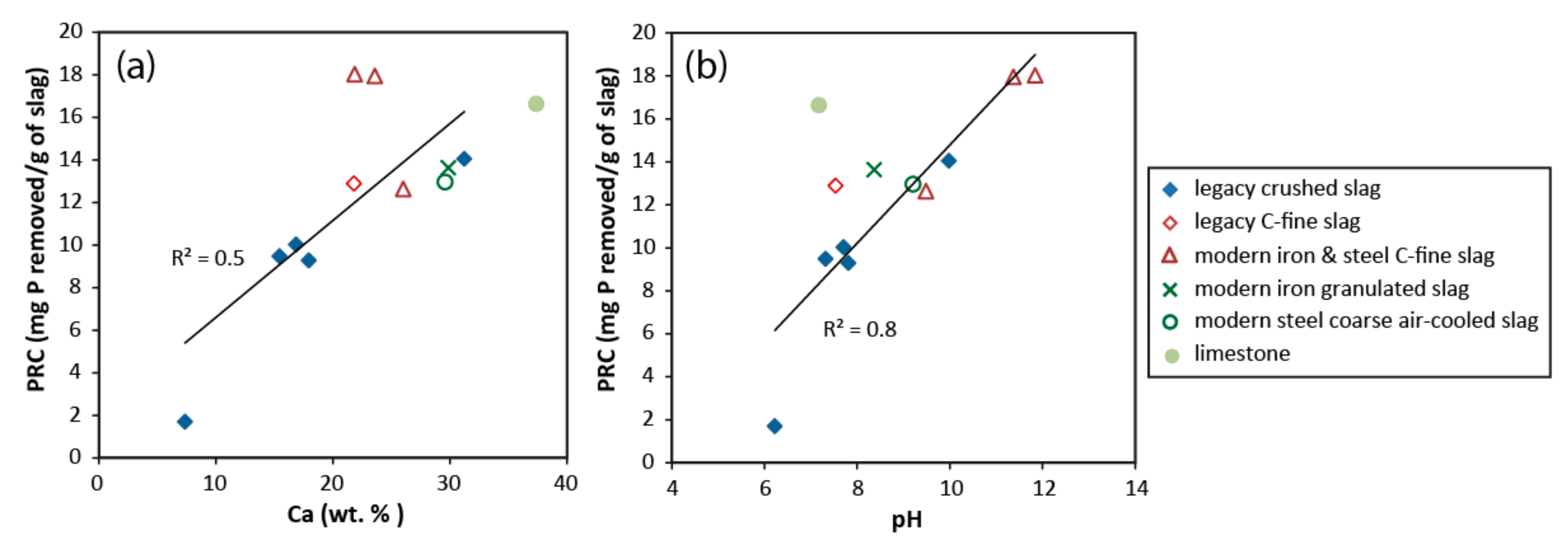
3.5. Phosphate Removal Capacity

Batch experiments on slag using the size fraction given in Table 1 and a synthetic phosphate solution (deionized water and dissolved KH2PO4) reacted to a pseudo-steady state demonstrate efficient removal of phosphate from solutions with initial phosphate concentrations ranging from 10 to 1085 mg P/L (Table 4). At the lowest tested phosphate concentration of 10 mg P/L, 12 of the 13 slags removed all or nearly all of the phosphate from the solution (98–100% retained in solid), with the lowest removal of 98% measured for the coarse air-cooled blast-furnace slag (USSFeair). The USSFeair sample was not crushed and one piece of slag weighing approximately 50 g was used in the batch experiment. This sample also had the lowest specific surface area (0.23 m2/g) [31]. The lower exposed surface area for this sample compared to most other samples that were <9.5 mm size-fraction splits may explain the lower amount of phosphate removal. The only other sample that was not <9.5 mm was USSSteelB_3/8-4. This sample’s specific surface area (0.84 m2/g) was greater than USSFeair and similar to several of the <9.5 mm size fraction samples. USSSteelB_3/8-4 may be more vesicular when compared to USSFeair, resulting in the higher surface area and a slightly more efficient removal of phosphate. The only sample that had a significantly lower phosphate removal was slag from a legacy site (ILSS8), which only removed 75% of the phosphate from the 10 mg P/L solution. This sample contained the lowest Ca concentration and the highest Al and Fe concentrations. Additionally, the mineralogy was unique with significant plagioclase feldspar and hematite, which are atypical primary phases in ferrous slag [1]; this sample may have contained non-slag materials, in addition to being weathered.
Four slag samples and a limestone sample were tested in batch experiments using increasingly higher phosphate leachant concentrations (54, 108, 256, and 501 mg P/L; Table 4). The following indicates the phosphate-removal effectiveness of the samples tested: AMSteelC and AMFeC > ILSS1 > limestone > ILSS2. The modern C-fines retained all of the phosphate for the four leachant concentrations tested, whereas the legacy samples (ILSS1 and ILSS2) were less effective. The final set of batch experiments using a 1085 mg P/L leachant solution resulted in only partial removal of the phosphate for all tested samples. These results provided data for the calculation of a maximum phosphate removal capacity (PRC in mg P/g slag):
PRC = ((Pin − Pef)V)/M
where Pin is the initial leachant phosphate concentration in mg P/L, Pef is the effluent leachate phosphate concentration (mg P/L), V is the volume of solution (L), and M is the mass of the slag (g) (Table 4).
Overall, the most effective slags for phosphate removal are two modern air-cooled C-fines (AMFeC and AMSteelC) with PRCs of 18 mg P removed for each gram of slag (mg P/g of slag); this is currently the least marketable type of slag because the larger air-cooled fractions are generally preferred for use in construction materials (e.g., ballast, riprap, and gabion) and granulated glassy slag is sold for use in cement. Limestone was also effective with a PRC of 17 mg P/g of limestone. Several modern and legacy samples performed similarly and include: modern granulated iron (USSFegran), modern air-cooled coarse and C-fine steel slag from the Gary Works location (USSSteelB_3/8, USSSteelC), legacy C-fines (ILSS2), and legacy air-cooled (ILSS1), all with PRCs between 13 to 14 mg P/g of slag. Slightly less effective were air-cooled slag from several legacy sites (ILSS5, ILSS6, and ILSS7), with PRCs between 9 to 10 mg P/g of slag, and the least effective was legacy air-cooled ILSS8 (PRC of 2 mg P/g of slag) (Table 4).

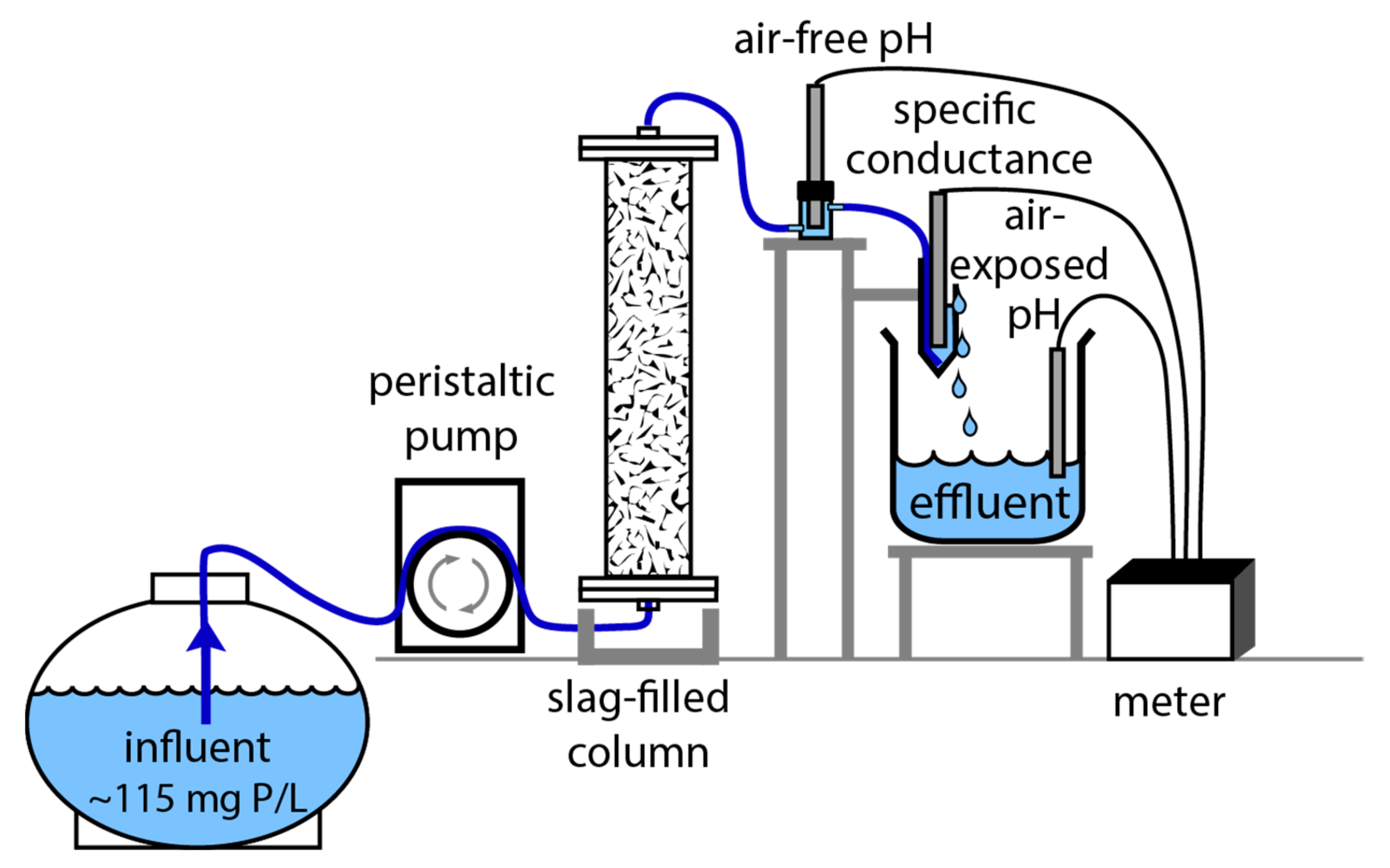
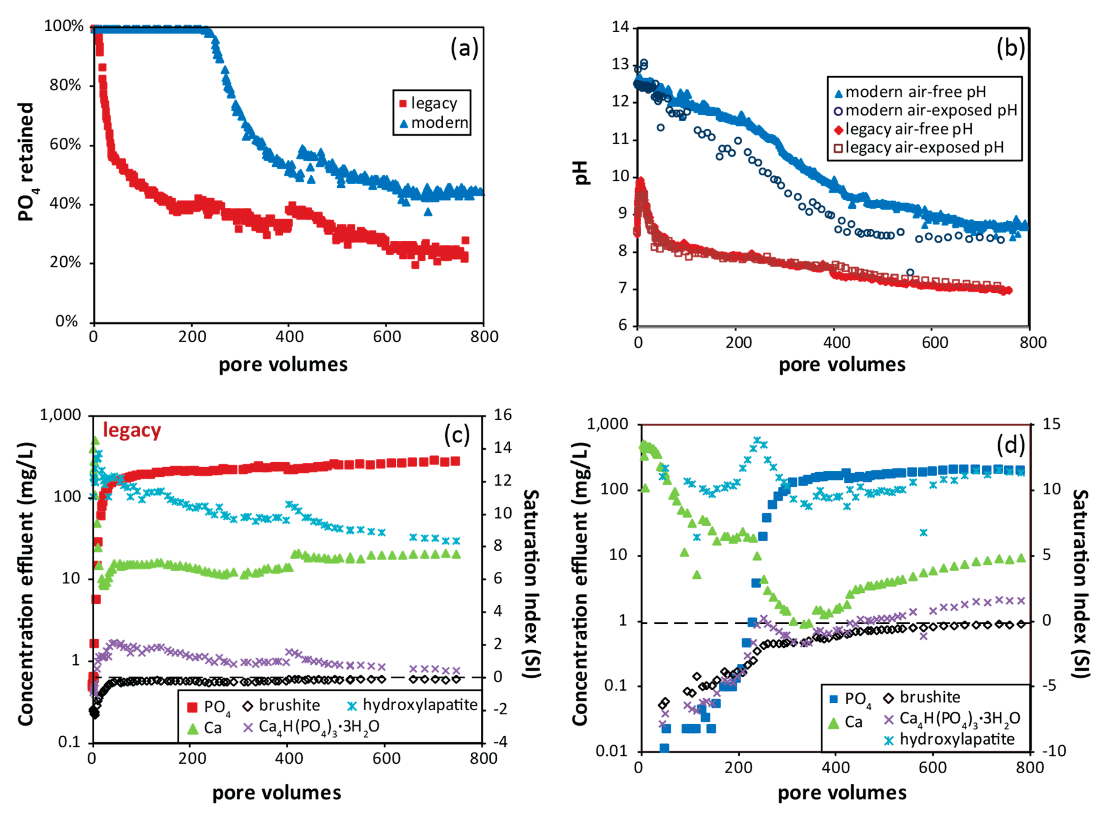
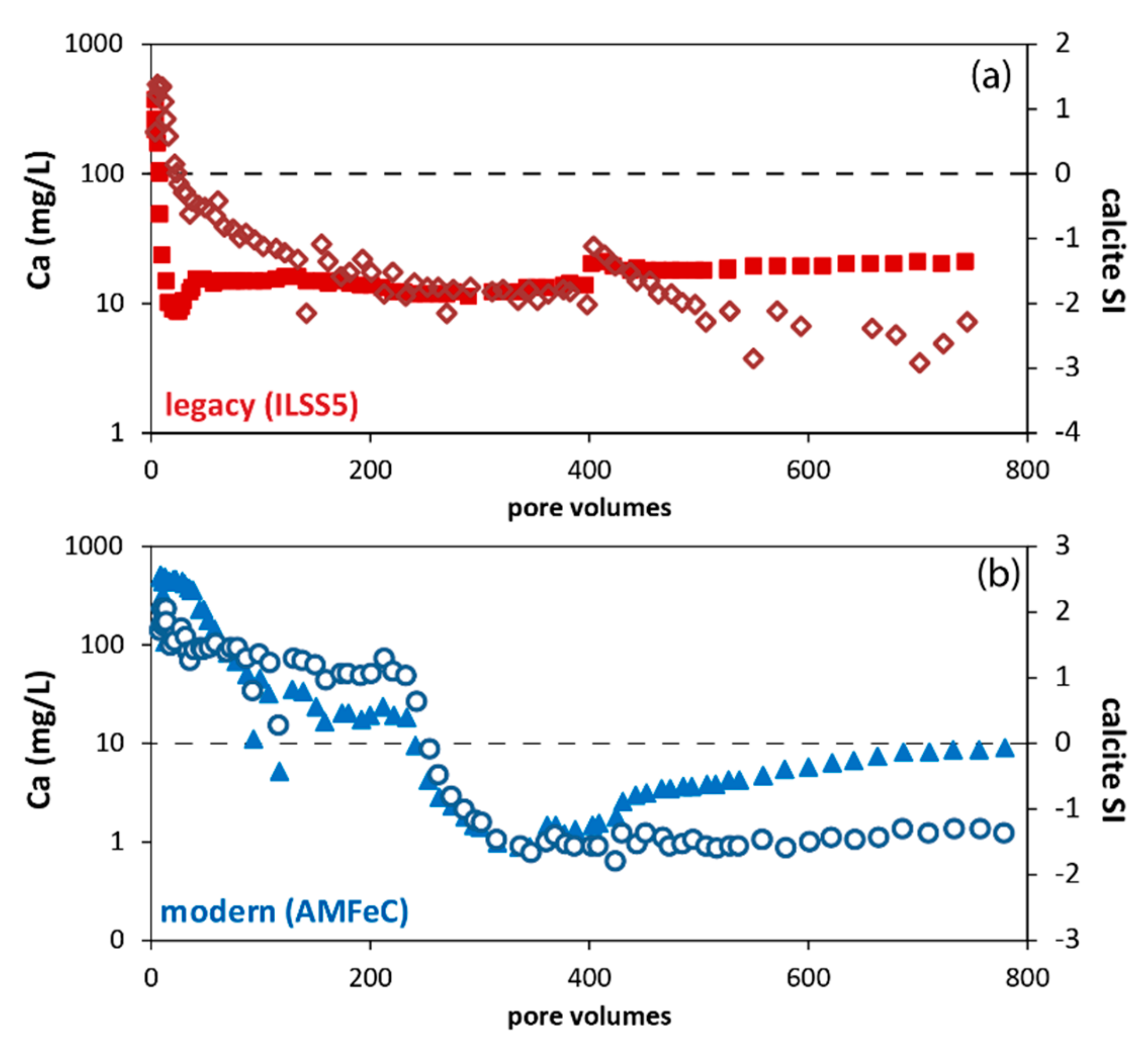
3.6. Phosphate Removal Column Experiments

Two samples, one from a legacy site (ILSS5) and one from a modern iron slag (AMFeC) from Indiana Harbor were chosen to monitor the phosphate removal ability over time by conducting long-term flow-through column experiments. The slag from the legacy site (ILSS5) was chosen because it performed similarly during the batch experiments to several other legacy slag samples (PRC between 9 and 10 mg P/g of slag) and contains similar Ca concentrations (22 to 25 wt. % CaO). As for the modern iron C-fine slag (AMFeC), its major element chemistry was similar to several modern steel slags and had one of the highest PRC (18 mg P/g of slag). For the experiments, approximately 760 (ILSS5) and 790 (AMFeC) continuous pore volumes of ~115 mg P/L synthetic influent solution with a HRTv of ~8 h were reacted with the slag samples in the columns. The results of the long-term column experiments are consistent with the shorter-term batch experiments in that they demonstrate that modern iron C-fine slag (AMFeC) has a higher PRC compared to composited crushed legacy slag from site ILSS5 (Figure 3). In addition, the column experiments reveal that the modern sample tested was effective over a longer period of time and resulted in slightly different reacted effluent chemistries (Figure 3). As shown in Figure 3a,c, the legacy slag initially retained nearly all the phosphate from the influent solution resulting in low effluent phosphate concentrations. However, after only approximately seven pore volumes, the percentage of phosphate retained decreased at an exponential rate. Another slope change occurred after approximately 170 pore volumes, after which the percent phosphate removal efficiency of the slag decreased only by small increments. At 170 pore volumes, the legacy material was only retaining about 40% of the influent phosphate. In contrast, the modern material was effective at removing nearly all of the phosphate from the influent for a longer duration (over 230 pore volumes) compared to legacy slag (Figure 3a,d). After the initial exponential decrease in the retention efficiency for the modern slag-filled column, the percent of phosphate retained leveled off to approximately 50% phosphate at approximately 400 pore volumes, with only small decreases after. Because the influent chemistry changed slightly at around 420 pore volumes (a new batch of influent was passed through the columns), the percentage of phosphate retained was affected (Figure 3a) and therefore, the change from an exponential to a gradual slope was difficult to pinpoint. Calcium concentrations displayed a reverse trend to phosphate concentrations in the effluent (Figure 3c,d), generally decreasing exponentially, then reaching a steadier value.
The pH of effluent from the modern C-fine slag column was higher than that from the legacy slag sample column for the duration of the experiment (Figure 3b). The air-free pH (i.e., before exposure to the atmosphere) of the effluent for the modern C-fine slag column generally fluctuated between 12.5 and 12.7 for the first 20 pore volumes, after which, it decreased incrementally. The air-free pH measured approximately 8.7 at the end of the experiment. In contrast, the air-free pH of the effluent from the legacy-slag-filled column began at 8.5 and then increased to 9.9 during the first seven pore volumes, after which it deceased incrementally, reaching an air-free pH of 7.0 by the end of the experiment (Figure 3b). The air-exposed pH measured after the effluent was exposed to the atmosphere is also shown in Figure 3b. Air-free and air-exposed pH measurements for the effluent from the legacy slag column were similar in contrast to those from the modern C-fine slag column, for which the air-exposed pH was as much as 1 pH unit lower.
The column experiments were decommissioned after almost 9 months at which time 17 and 13 mg P per gram of slag were removed for AMFeC and ILSS5, respectively. Both columns at the end of the experiment were removing phosphate from the influent solution, albeit at less than 50% efficiency (Figure 3a).

4. Discussion

4.1. Environmental Characteristics of Slag Samples

The U.S. Environmental Protection Agency has established Regional Screening Levels (RSL) for chemical contaminants in soils at hazardous waste sites, which are non-site specific or element-speciation specific and provide a screening value for residential and industrial reuse scenarios [37]. Canada has similar soil guidelines [38], which were used in this analysis if USEPA guidelines were not established for an element. Land use for the legacy sites currently does not include plans for residential use, however, several sites are used for recreation such as hiking and biking trails [26]. Therefore, the lower concentration residential-use soil guidelines may be more applicable to some sites compared to the less stringent industrial-use guidelines. Slag compositions from nearly all sites exceeded the residential- and industrial-use screening levels of 64 and 87 mg/kg Cr, respectively, based on the Canadian soil guidelines [38]. For element concentrations in the slag, see Hoppe et al. [31]. The exception is granulated iron slag (USSFegran) for which the Cr concentration exceeded the residential-use soil guidelines but not the industrial-use guideline. In addition to Cr, the concentrations of Mn in all slag samples exceeded the residential-use soil guideline (0.18 wt. % Mn); several slags from legacy sites and the three steel slags from USS Steel exceeded the industrial-use soil guideline (2.3 wt. % Mn). The presence of these elements in notable concentrations is likely due to both being added to steel to impart specific properties (i.e., Cr improves corrosion resistance and Mn assists in the deoxidation of steel and promotes strength). Lead exceeded the residential-use RSL in one legacy site sample (ILSS2) with 570 mg/kg Pb, but not the industrial-use RSL. Arsenic also exceeded RSLs in most samples, however, the guideline values are lower than the average natural soil concentration in the USA [39].
The SPLP leaching tests were performed to gain insight into the potential release of contaminants from the slag samples into the surrounding ecosystem due to weathering, specifically effects on groundwater and surface water chemistry. As already discussed in Section 3.3, high pH, alkalinity, and hardness waters were produced when water interacted with these slags. In addition, generic water quality guidelines can be used to compare element concentrations in SPLP leachates to evaluate if potentially toxic elements were leached in significant amounts. Thus, the results of the SPLP tests are compared to USEPA or World Health Organization (WHO) Drinking Water Regulations and USEPA National Recommended Water Quality Criteria for aquatic life [40,41,42]. Some guidelines for specific elements are qualified. The USEPA National Drinking Water Regulations or maximum contaminant levels (MCLs) for several elements of interest, including Al and Mn, are secondary standards that are recommended as reasonable goals and largely address the aesthetic properties of water but are not enforceable values. There is also a secondary guideline for a pH of 6.5–8.5. In addition, the WHO Drinking Water Guideline is provisional for Cr.
The elements that exceeded water quality guidelines in the SPLP leachates are Al, Cr, and Mn. Chromium and Mn also exceeded soil guidelines based on bulk chemistry. Chromium in all SPLP leachates was below the USEPA MCL of 100 µg/L, however, the leachate from ILSS2 contained 56 µg/L Cr, which is just above the 50 µg/L provisional drinking water guideline from the WHO. Despite almost all bulk samples exceeding the industrial-use soil guideline, Cr did not appear to be present in a leachable soluble form. Manganese is similar to Cr in that most samples exceeded soil guidelines, yet only one SPLP leachate from ILSS8 contained Mn in an appreciable amount; the concentration in the leachate of 59 µg/L exceeded the USEPA secondary MCL of 50 µg/L. Additionally, Al exceeded the USEPA secondary drinking water guideline of 50 to 200 for aesthetic properties in SPLP leachate produced from all the slag samples tested [31]. Aluminum is the only element that was present in concentrations that also exceeded freshwater aquatic life criteria [41]. Only the iron granulated slag (USSFegran) did not exceed the USEPA Criterion Continuous Concentrations (CCC) or the Criterion Maximum Concentration (CMC) for Al. A few samples contained concentrations of Fe above the USEPA secondary MCL and the pH of all SPLP leachates exceeded the secondary guideline. In general, the bulk chemical concentrations of these elements do not correlate with the amount of the element that leached into solution, suggesting elements were hosted in more than one mineralogical phase and that the phases had variable solubilities. Also, Pb and As did not exceed water quality guidelines in any SPLP leachates, despite exceedances of soil guidelines based on the bulk chemistry.
Overall, based on simulated weathering tests, the most significant environmental concerns for water that was generated after interacting with these slags are high pH, high alkalinity, and, potentially, high Al concentrations. Drinking water guidelines exceeded based on element concentration are either secondary (for aesthetic purposes), or provisional guidelines. The only element that exceeded the freshwater aquatic life criterion was Al. Therefore, the leaching of almost all elements in quantities that threaten the health of the aquatic community or humans does not seem to be a substantial issue for these slag samples.

4.2. Acid Neutralizatino and Potential for Application in Water Treatment

ABA suggests that modern and legacy iron and steel slags are extremely alkaline materials with the potential to be used to neutralize acid. The high paste pH (10 to 12.5), which is a measurement of the equilibrated (i.e., steady) pH of a deionized-water-saturated sample, and the pH (9.7 to 12.3) of the SPLP leachate solutions (i.e., reacted for 18 h) were similar and positively correlated (R2 = 0.9), suggesting the shorter-term reaction test (paste pH) is a good indicator of the longer-term (on the order of hours to a day) simulated weathering behavior of these samples. The alkaline pH of the reacted solutions and the high neutralization potentials of up to 860 kg CaCO3/t are the consequence of various mineral dissolution reactions during the ABA procedure. The NP and NNP values both positively correlate (R2 = 0.9) with the amount of Ca in the slag (Figure 4). As previously mentioned, the neutralization generated by the slag samples reached over 80% of the theoretical neutralization generated by pure calcite (i.e., 1000 kg CaCO3/t) (Figure 4). The Ca minerals present in these slag samples in major (over 10 wt. %) to minor (1–10 wt. %) amounts based on XRD include calcite (CaCO3), lime (CaO), larnite (Ca2SiO4), åkermanite–gehlenite (melilite group) (Ca2Mg(Si2O7) to Ca2Al(AlSiO7)) and brownmillerite–srebrodolskite (Ca2(Al,Fe)2O5 to Ca2Fe2O5), among others. The Ca-bearing minerals may consume acid during hydrolysis, explaining the correlation between pH and Ca content. The following are dissolution reactions for several of the Ca minerals found in the slag:
CaCO3 + 2 H+ → Ca2+ + H2O + CO2,
Ca2SiO4 + 4 H+ → 2 Ca2+ + 2 H2O + SiO2,
Ca2MgSi2O7 + 6 H+ → 2 Ca 2+ + Mg2+ + 3 H2O + 2 SiO2,
Ca2Fe2O5 + H2O + 4 H+ → 2 Ca2+ + 2 Fe(OH)3,
The most abundant Ca carbonate mineral in the slag sample was calcite, which reached up to tens of wt. %, but more commonly was present in a just few weight percent. The other Ca carbonate minerals were less than 10 wt. %. The sample with the highest estimated calcite content (ILSS2) had an NP of 760 kg CaCO3/t. Assuming complete dissolution of calcite present in this sample (approximately 25 wt. % calcite), the NP contributed to by calcite would theoretically have been approximately one-third of the total NP (i.e., ~250 kg CaCO3/t). For most of the samples, the NP contribution from calcite and other Ca carbonates was significantly less (<15 wt. % calcite). This suggests that although calcite and other Ca carbonates contribute to the high NP of these samples, the dissolution of other Ca minerals play a substantial role in the consumption of acid. The amount of acid consumed by one mole of the other Ca mineral phases found in the slag samples is variable, as shown in Equations (2)–(5). For example, larnite and åkermanite have the potential to consume more acid than calcite on a mole basis, assuming complete dissolution.
The solubility of the phases will also influence how much acid neutralization each phase contributes. Lime (CaO) is several orders of magnitude more soluble than CaCO3; in general, calcite is more soluble than the Ca silicates [43,44]. According to experiments on the carbonation of steel slag by Kasina et al. [45], the larnite in a steel slag sample was susceptible to dissolution in deionized water, rankinite (Ca3Si2O7) was dissolved to a lesser degree, and srebrodolskite was insoluble. The various solubilities suggest that the neutralization contribution by a specific mineral may change over time as more soluble minerals weather initially and less soluble minerals weather at a slower rate, which makes them persist longer. A potential dissolution series is lime, contributing initially, followed by calcite, then larnite, and in the extended timeframe, srebrodolskite and melilite. Other non-Ca phases present, such as Mg and Al silicates will also contribute to the neutralization potential, especially in the long-term after more soluble phases have been exhausted.
Legacy slag sample ILSS8 had the lowest NNP of 65 kg CaCO3/t and was composed of plagioclase feldspar, spinel, hematite, melilite, and pyroxene. Some of these phases, such as the feldspar and hematite are less typical for ferrous slags [1]. Therefore, this sample may have been a mixture of slag and non-slag materials, resulting in a lower NNP compared to the other samples.
There are several properties of the iron and steel slags from the Chicago-Gary area that make them a favorable material for use as a neutralizing agent. First, based on simulated weathering tests (SPLP), the leaching of potentially harmful trace elements does not seem to be a major issue with these slag samples. Second, the NP of several slags was almost as high as pure limestone. However, steelmaking facilities are willing to provide certain types of slag at little to no cost. In addition, unlike other chemicals used in acid-treatment systems such as Na hydroxide, slag is not caustic, therefore, handling and transporting the slag is not an issue. Lastly, the slags are reactive, with some generating a very high air-free pH. The air-free pH, based on the phosphate column experiments, then decreases; however, for the modern slag tested, the air-free pH remained above pH 8 for the 9-month experiment (Figure 3b), indicating the dissolution of acid-consuming minerals continued in the long-term.
The slags with the highest NNP may be useful in treating acid-mine drainage (AMD) from coal or base-metal mines. Simmons et al. [17] utilized ferrous slag as a filter in a leach bed that successfully neutralized acidic coal-mine drainage in West Virginia, USA. Kruse et al. [20] reported mixed success based on field- and laboratory-based studies using steel slag to treat AMD in Ohio, USA. Others reported success and failure with iron and steel slag for treating AMD for static and kinetic laboratory-based studies [19,22]. Armoring of slag used in treatment systems (e.g., Equation (5)), hydraulic clogging, and loss of NP are all reported problems that may need engineering and chemical solutions to improve effectiveness and longevity of AMD treatment systems [7,21,36].

4.3. Phosphate Removal Mechanisms and Chemistry of Reacted Solutions

The chemistry of the effluent solutions from the batch and column experiments provides insight into phosphate removal mechanisms. The PRC positively correlates (R2 = 0.5) with bulk Ca content (Figure 5a), similar to the finding for NNP and bulk Ca concentrations (Figure 4). Interestingly, samples of C-fines from the Indiana Harbor location (AMFeC and AMSteelC) had substantially higher PRC (~18 mg P/g) than C-fines from Gary Works (USSSteelC) and legacy fines (ILSS2) (Table 4), despite having comparable bulk Ca contents (Figure 1) and similar mineralogies. The phosphate removal capacity correlation with batch experiment effluent pH is greater (R2 = 0.8) than that observed for Ca content for slag samples, partially due to the Indiana Harbor C-fines placement in Figure 5b. This suggests that effluent pH may be a stronger indicator of material with high PRC than bulk Ca concentration. The variations in pH were due to differences in bulk chemistry as well as in primary mineralogy. The pH of the effluent may indicate the abundance of readily soluble Ca minerals that consume acid upon dissolution and increase pH (see Reactions (2) to (5)) as discussed in the previous section. Also, legacy slag is weathered, therefore, readily soluble Ca phases, some of which consume acid, may have already been dissolved and washed away, resulting in generally lower effluent pH.
Calcite likely contributes to acid consumption during slag–solution interactions (Reaction (2)), but it also may contribute to acid generation based on the pH measured in column effluent. As previously discussed, two pH measurements were made on column effluent solutions, one before the effluent was exposed to the atmosphere (air-free pH) and one after (air-exposed pH) (Figure 1). The air-free and air-exposed pH of the effluent from the column containing the legacy slag (ILSS5) were similar and did not reach above 10 (Figure 3b). However, the more alkaline pH effluent (started at above 12) from the column containing the iron C-fine slag (AMFeC) resulted in air-free pH values as much as one pH unit higher than air-exposed pH values (Figure 3b). The change in pH suggests that the chemistry for these solutions was dynamic during initial exposure and re-equilibration with the atmosphere. The concentrations of Ca in the effluent and the saturation indices for calcite are shown in Figure 6. For the column filled with legacy slag, the concentration of Ca decreased steeply and then maintained a generally consistent concentration (Figure 6a). In contrast, the concentration of Ca in the effluent from the modern slag-filled column decreased and then maintained a generally steady concentration until approximately 220 volumes after which it decreased and, then, eventually steadily increased (Figure 6b). Based on geochemical modeling, the initial plateau for the modern slag effluent (before 240 pore volumes) coincided with a calcite saturation index of approximately one. This plateau suggests saturation with respect to a phase. During that time, the effluent collected in the beaker formed a white precipitate on the sides of the beaker and floating on top of the effluent solution. The precipitate was collected and analyzed by XRD at various times during the first 200 pore volumes of flow. Calcite, as well as aragonite and vaterite, both polymorphs of calcite, were consistently identified. Therefore, although the effluent may not have been in equilibrium (SI = 0) with respect to calcite, the SI plateau may indicate saturation with respect to another phase, possibly another form of CaCO3. Another explanation warranting further study is that a Ca-carbonate-phosphate may have controlled both the concentration of Ca in the effluent and played a role in removing phosphate from solution. In the modern slag column, the carbonate was likely stripped from the influent solution while flowing through the column and interacting with the slag for approximately 8 h. The air-free pH was measured on the effluent that was not in equilibrium with CO2 in the atmosphere; in fact, reaction with the slag should have stripped the solution of all carbonate species. The air-exposed pH was measured on effluent that has been exposed to the atmosphere; equilibration with CO2 resulted in calcite precipitation which generated hydrogen ions and a lower air-exposed pH measurement (Reaction (2) in reverse). A similar process was documented by Gahala et al. [26] in a brownfield site underlain by iron and steel slag near Chicago. These results may have implications for field deployment of slag filters to remove phosphate from solutions in that the precipitation of calcite or other carbonate or phosphate phases remove Ca ions from solution and, at a treatment system outlet, may cause clogging issues.
As previously discussed, the PRCs of the ferrous slag samples correlate with bulk Ca concentrations and effluent pH based on the batch experiments. Calcium minerals in the slag dissociate during slag–solution interactions and dissolved Ca may combine with the phosphate and form Ca phosphates, the main reactions responsible for phosphate removal from the batch and column experiments. Slag that contained higher amounts of soluble Ca minerals resulted in a higher concentration of dissolved Ca that was available to combine with the phosphate and precipitate. The formation of secondary Ca phosphate phases was documented by XRD. White coatings on reacted slag from batch experiments were identified as Ca phosphate phases, most commonly brushite (CaHPO4∙2H2O), but also monetite (CaHPO4), and apatite phases such hydroxylapatite (Ca5(PO4)3(OH)) and carbonate-hydroxylapatite (Ca5(PO4,CO3)3(OH)). Calcite was also identified in the white coatings, the formation of which may actually inhibit phosphate removal because it may have removed dissolved Ca from solution [9]. Secondary coatings consisting of brushite were also observed on limestone after interaction with the synthetic phosphate solution used in the batch experiments.
The Ca phosphate phase that forms depends on the concentrations of dissolved phosphate and Ca and the pH conditions. In general, the lower the Ca:P ratio, the more acidic and water-soluble the Ca phosphate phase [46]. Under acidic to near neutral pH (2.0–6.0) and Ca/P molar ratios of 1.0, brushite or dicalcium phosphate dihydrate [CaHPO4∙2H2O] is predicted to form from aqueous solutions. As pH increases (5.5–7.0) and the Ca/P moral ratio increases (1.33), octacalcium phosphate [Ca8(HPO4)2(PO4)4∙5H2O] may form; this phase is commonly transient and will convert to a more stable Ca phosphate phase such as Ca-deficient hydroxylapatite. Ca-deficient hydroxylapatite [Ca10−x(HPO4)x(PO4)6−x(OH)2−x (0 < x < 1)], is predicted to be stable at Ca/P of 1.5 to 1.67 and pH of 6.5 to 9.5 and hydroxylapatite [Ca5(PO4)3(OH)] at Ca/P of 1.67 or greater and pH of 9.5 to12. Ca-deficient hydroxylapatite may age to hydroxylapatite [Ca5(PO4)3(OH)] [46]. The solubility of these phases is very low for compounds forming under neutral to basic conditions and high for the phases that form under acidic conditions. In addition, amorphous Ca phosphates have also been found to form before crystallizing to more stable forms [46]. Bowden et al. [6] reported a sequence of Ca-phosphate phases on reacted steel slag in column experiments from the most soluble brushite to octacalcium phosphate and hydroxylapatite over time. Interestingly, the legacy slag (ILSS5) in this study generated an effluent that, based on geochemical modeling, was oversaturated with respect to hydroxylapatite and octacalcium phosphate (represented in the geochemical database as Ca4H(PO4)3∙3H2O), but after 40 pore volumes, was approximately saturated with respect to brushite (saturation index ~ 0) (Figure 3c). Based on the pH of the effluent after 40 pore volumes of flow (air-free pH 8.7–6.9), brushite was not the predicted phase based on experimental studies [46]. However, brushite was identified by XRD in precipitate that formed in the effluent from this column, supporting the results of the geochemical modeling. Secondary coatings on reacted slag within the column were found to be brushite, hydroxylapatite and octacalcium phosphate. Figure 7a shows tabular brushite crystals on reacted slag from the column filled with legacy slag (ILSS5). Other secondary phases identified on reacted slag from this column include Fe and Ca phosphate phase (Figure 7b): the tabular morphologies are Fe phosphate and the finer-grained radiating rosette-shaped plates are mixtures of Fe, Ca and phosphate. The tabular morphology is consistent with vivianite (Fe2+3(PO4)2∙8H2O). Figure 7c shows layers of secondary Ca phosphates, some with trace amounts of Mn and Mg, coating the reacted silicate-rich slag.
Geochemical modeling of Ca-phosphate phases in effluent from the column filled with modern slag (AMFeC) results in saturation indices that are oversaturated for hydroxylapatite; however, brushite and octacalcium phosphate saturation indices approach zero after approximately 250 pore volumes (Figure 3d). As the experiments progress (around 500 pore volumes and more), brushite is suggested to be saturated and controlling the concentrations of Ca and phosphate (Figure 3d). However, the formation of Ca-deficient hydroxylapatite or hydroxylapatite are reported to be the phases which form from more alkaline solutions [46], such as those for this column effluent (pH 8.7 or higher). Brushite, as well as hydroxylapatite, were identified in precipitate that formed in the effluent from this column and brushite, octacalcium phosphate, and hydroxylapatite (Figure 7d) were determined to be present as secondary coatings on reacted slag after the column was decommissioned. Other phases observed include a mixed Ca and Mg phosphate phase and a mixed Ca and Zn phosphate phase (Figure 7e,f).
Based on geochemical modeling, and observed precipitates and secondary coatings, the formation of Ca phosphate phases was the main mechanism for phosphate removal as the column experiment progressed. As shown in Figure 7, other phosphate phases containing both Ca and other cations were identified based on SEM. These phases, potentially amorphous to crystalline equivalents of phosphate minerals such as vivianite, whitlockite (Ca(Mg,Fe2+)(PO4)6PO3OH), and parascholzite (CaZn2(PO4)2∙2H2O), may not be represented in the thermodynamic database and, therefore, were unable to be modeled. Other mechanisms may drive phosphate removal prior to direct phosphate precipitation and require further investigation. The high amount of Fe in the slag present as Fe-oxides, mainly wüstite and magnetite, may play a role in phosphate removal. Sellner et al. [47] reported that steel chips and iron filings remove phosphate more effectively than natural minerals and steel slag and attributed the removal to surface complexes, electrostatic adsorption and Fe-phosphate precipitation. A secondary Ca- and Fe-phosphate mixed phase was identified on reacted slag from the legacy-slag-filled column (Figure 7b). In addition, calcite actively precipitated from effluent generated in the modern slag column for approximately the first 240 pore volumes, generally the same duration that brushite and octacalcium phosphate were undersaturated. During these initial pore volumes, primary Ca phases in the slag and secondary calcite may have provided sorption sites for phosphate. According to Bowden et al. [6], absorbed phosphate on calcite may form nucleation sites from which precipitation of Ca phosphates may occur; however, limited sites are likely available on the calcite. Further, most of the secondary calcite began forming only after the effluent was exposed to atmospheric CO2. Iron phases in the slag may also provide sorption sites; however, sorption of phosphate would likely be limited under these high-pH conditions [48,49]. Additionally, phases not in the thermodynamic database such as amorphous Ca phosphate, Ca-phosphate-carbonates, or Ca-deficient hydroxylapatite may also play a role.
After the phosphate removal efficiency of both columns declined sharply, a much slower decline was observed and maintained for many pore volumes (Figure 3a). Initially, the dissolution of the more soluble Ca-bearing minerals provided readily available Ca to combine with the phosphate. The sharp decline may be explained due to exhaustion of soluble Ca phases and/or armoring of slag grains by precipitates inhibiting their dissolution. Subsequently, the influent solutions became a significant source of Ca ions available for Ca-phosphate precipitation. Modeling indicates that the influent solution used was supersaturated with respect to brushite, and white precipitates appeared to continue to accumulate in the column for the duration of the experiment. Slag dissolution facilitated the initial nucleation of phosphate precipitation, which continued to occur due to a continuous supply of Ca in the influent. This effect was also observed by Bowden et al. [6]. This has interesting implications for water treatment scenarios such that phosphate removal may continue past predictions based on a slag’s PRC if the water to be treated is a source of Ca ions to the system. However, the precipitation of calcite and Ca phosphate may eventually decrease the hydraulic conductivity and dispersivity in treatment systems.
Using modern or legacy steelmaking slag from the Chicago-Gary area as a filter material may be a viable option for treating nutrient-rich waters. Laboratory studies of steelmaking slag filters have been documented around the world with lesser reports for field implementation. For example, Penn et al. [50] utilized electric arc furnace slag from Indiana, USA, to treat farm and golf course runoff. Additionally, Barca et al. [9] tested electric arc furnace and basic oxygen furnace slag from Spain and France, respectively, in a waste-water treatment wetland. These and numerous other studies document removal, predict treatment efficiency and longevity, and suggest effective design scenarios based on field studies [5,8,50,51,52]. An important consideration for field implementation is the potential to release phosphate back into solution. Sellner et al. [47] found that steel slag showed much less phosphate desorption (less than 1% for batch experiments) than other materials such as limestone. Sellner et al. [47] suggested that strong chemical bonds are formed between the slag and phosphate, potentially preventing phosphate release when phosphate concentrations or other chemical constituents vary in the treatment water. Another important consideration is regeneration of slag material after secondary calcite and phosphates have rendered the slag removal capacity exhausted. Investigations on regenerating slag by physical and chemical techniques reported mixed results but with some promising outcomes [4,5,8]. Overall, the results of the batch and column experiments in this study suggest iron and steel slags from the Chicago-Gary area have the potential for use as a filter substrate to adsorb phosphate. Scaling the experiment up to a field scale is an important next step to identify potential issues with large-scale implementation such as phosphate removal efficiency degradation, clogging, and desorption of phosphate.

5. Conclusions

Steelmaking slag may be a viable option for use in removing phosphate from municipal wastewaters or agricultural runoff or to treat acid solutions, such as acid-mine drainage. Because the bulk Ca content of the ferrous slags generally correlates with its effectiveness to remove phosphate and neutralize acid, determining the Ca content may be a useful initial assessment for identifying and ranking potential usable slag materials. Promoting the utilization of steelmaking slag may reduce the amount disposed as waste at modern facilities. In addition, it may help offset restoration costs at legacy sites such as those in the Chicago-Gray area where slag dumps are located in the vicinity of urban and agricultural areas with high nutrient loading to local waterways. Finding added value in ferrous slag supports the recent emphasis on progressing toward a circular economy of minimizing waste and maximizing the value from our resources.

Author Contributions

Conceptualization, N.M.P., R.R.S.II and P.M.B.; methodology, N.M.P., R.R.S.II, and D.A.H.; formal analysis, N.M.P., D.A.H. and C.J.G.; investigation, N.M.P., R.R.S.II, and D.A.H.; data curation, N.M.P. and D.A.H.; writing—original draft preparation, N.M.P.; writing—review and editing, R.R.S.II, D.A.H., C.J.G., and P.M.B.; funding acquisition, R.R.S.II, P.M.B., N.M.P.

Funding

This research was funded by U.S. Geological Survey Mineral Resources Program and U.S. Geological Survey Midwest Region Science Flex Funds.

Acknowledgments

The authors thank Arcelor Mittal S.A. and U.S. Steel Corporation for providing modern steelmaking slags. Travis Cole and Robert Kay, of the U.S. Geological Survey, assisted in collecting slag samples at legacy sites. Harvey Belkin, of the U.S. Geological Survey, provided helpful review comments that improved the text. Thanks to Paul Hackley and others at the U.S. Geological Survey who switched my beakers. Any use of trade, product, or firm names is for descriptive purposes only and does not imply endorsement by the United States government.

Conflicts of Interest

The authors declare no conflict of interest.

References

  1. Piatak, N.M.; Parsons, M.B.; Seal, R.R., II. Characteristics and Environmental Aspects of Slag: A Review. Appl. Geochem. 2015, 57, 236–266. [Google Scholar] [CrossRef]
  2. Van Oss, H.G. Slag, iron and steel. U.S. Geol. Surv. Miner. Yearb. 2018, 1, 69.1–69.8. [Google Scholar]
  3. Baker, M.J.; Blowes, D.W.; Ptacek, C.J. Laboratory development of permeable reactive mixtures for the removal of phosphorus from onsite wastewater disposal systems. Environ. Sci. Technol. 1998, 32, 2308–2316. [Google Scholar] [CrossRef]
  4. Drizo, A.; Comeau, Y.; Forget, C.; Chapuis, R.P. Phosphorus saturation potential: A parameter for estimating the longevity of constructed wetland systems. Environ. Sci. Technol. 2002, 36, 4642–4648. [Google Scholar] [CrossRef] [PubMed]
  5. Chazarenc, F.; Kacem, M.; Gérente, C.; Andrès, Y. ‘Active’ filters: A mini-review on the use of industrial by-products for upgrading phosphorus removal from treatment wetlands. In Proceedings of the 11th International Conference on Wetland Systems for Water Pollution Control, Indore, India, 1–7 November 2008; pp. 727–737. [Google Scholar]
  6. Bowden, L.I.; Jarvis, A.P.; Younger, P.L.; Johnson, K.L. Phosphorus removal from waste waters using basic oxygen steel slag. Environ. Sci. Technol. 2009, 43, 2476–2481. [Google Scholar] [CrossRef] [PubMed]
  7. Pratt, C.; Shilton, A.; Haverkamp, R.G.; Pratt, S. Assessment of physical techniques to regenerate active slag filters removing phosphorus from wastewater. Water Res. 2009, 43, 277–282. [Google Scholar] [CrossRef] [PubMed]
  8. Pratt, C.; Shilton, A. Active slag filters-simple and sustainable phosphorus removal from wastewater using steel industry byproduct. Water Sci. Technol. 2010, 62, 1713–1718. [Google Scholar] [CrossRef]
  9. Barca, C.; Gérente, C.; Meyer, D.; Chazarenc, F.; Andrès, Y. Phosphate removal from synthetic and real wastewater using steel slags produced in Europe. Water Res. 2012, 46, 2376–2384. [Google Scholar] [CrossRef]
  10. Barca, C.; Meyer, D.; Liira, M.; Drissen, P.; Comeau, Y.; Andrès, Y.; Chazarenc, F. Steel slag filters to upgrade phosphorus removal in constructed wetlands: Two years of field experiments. Environ. Sci. Technol. 2013, 47, 549–556. [Google Scholar] [CrossRef]
  11. Barca, C.; Meyer, D.; Liira, M.; Drissen, P.; Comeau, Y.; Andrès, Y.; Chazarenc, F. Steel slag filters to upgrade phosphorus removal in small wastewater treatment plants: Removal mechanisms and performance. Ecol. Eng. 2014, 68, 214–222. [Google Scholar] [CrossRef]
  12. Claveau-Mallet, D.; Wallace, S.; Comeau, Y. Removal of phosphorus, fluoride and metals from a gypsum mining leachate using steel slag filters. Water Res. 2013, 47, 1512–1520. [Google Scholar] [CrossRef] [PubMed]
  13. Claveau-Mallet, D.; Courcelles, B.; Comeau, Y. Phosphorus removal by steel slag filters: Modeling dissolution and precipitation kinetics to predict longevity. Water Sci. Technol. 2014, 48, 7486–7493. [Google Scholar] [CrossRef] [PubMed]
  14. Claveau-Mallet, D.; Boutet, É.; Comeau, Y. Steel slag filter design criteria for phosphorus removal from wastewater in decentralized applications. Water Res. 2018, 143, 28–37. [Google Scholar] [CrossRef] [PubMed]
  15. Sellner, B.M.; Hua, G.; Ahiablame, L.M. Fixed bed column evaluation of phosphate adsorption and recovery from aqueous solutions using recycled steel byproducts. J. Environ. Manag. 2019, 233, 595–602. [Google Scholar] [CrossRef] [PubMed]
  16. Ziemkiewicz, P.; Skousen, J. Steel slag in acid mine drainage treatment and control. In Proceedings of the Annual National Meeting of the Society for Surface Mining and Reclamation, Scottsdale, AZ, USA, 13–19 August 1999; Volume 16, pp. 651–656. [Google Scholar]
  17. Simmons, J.; Ziemkiewicz, P.; Black, D.C. Use of steel slag leach beds for the treatment of acid mine drainage. Mine Water Environ. 2002, 21, 91–99. [Google Scholar] [CrossRef]
  18. Cravotta, C.A., III. Assessment of Characteristics and Remedial Alternatives for Abandoned Mine Drainage: Case Study at Staple Bend Tunnel Unit of Allegheny Portage Railroad National Historic Site, Cambria Country, Pennsylvania, 2004; U.S. Geological Survey Open-File Report 2005-1283; United States Geological Survey: Reston, VA, USA, 2005; 52p.
  19. Gahan, C.S.; Cunha, M.L.; Sandström, Å. Comparative study on different steel slags as neutralising agent in bioleaching. Hydrometallurgy 2009, 95, 190–197. [Google Scholar] [CrossRef]
  20. Kruse, N.A.; Mackey, A.L.; Bowman, J.R.; Brewster, K.; Riefler, R.G. Alkalinity production as an indicator of failure in steel slag leach beds treating acid mine drainage. Environ. Earth Sci. 2012, 67, 1389–1395. [Google Scholar] [CrossRef]
  21. Goetz, E.R.; Riefler, R.G. Performance of steel slag leach beds in acid mine drainage treatment. Chem. Eng. J. 2014, 240, 579–588. [Google Scholar] [CrossRef]
  22. Name, T.; Sheridan, C. Remediation of acid mine drainage using metallurgical slags. Miner. Eng. 2014, 64, 15–22. [Google Scholar] [CrossRef]
  23. Bayless, E.R.; Greeman, T.K.; Harvey, C.C. Hydrology and Geochemistry of a Slag-Affected Aquifer and Chemical Characteristics of Slag-Affected Ground Water, Northwestern Indiana and Northeastern Illinois; U.S. Geological Survey Water-Resources Investigations Report 97-4198; United States Geological Survey: Reston, VA, USA, 1998; 67p.
  24. Bayless, E.R.; Schulz, M.S. Mineral precipitation and dissolution at two slag-disposal sites in northwestern Indiana, USA. Environ. Geol. 2003, 45, 252–261. [Google Scholar] [CrossRef]
  25. Roadcap, G.S.; Kelly, W.R.; Bethke, C.M. Geochemistry of extremely alkaline (pH > 12) ground water in slag-fill aquifers. Ground Water 2005, 43, 806–816. [Google Scholar] [CrossRef]
  26. Gahala, A.M.; Seal, R.R., II; Piatak, N.M. Preliminary Evaluation of Hydrologic and Chemical-Mass Balance, and Geochemical Modeling at Hyper-Alkaline Ponds of Big March, Chicago, Illinois. U.S. Geological Survey Scientific Investigations Report 2018; United States Geological Survey: Reston, VA, USA, in press.
  27. Carmichael, W.W.; Boyer, G.L. Health impacts from cyanobacteria harmful algae blooms: Implications for the North American Great Lakes. Harmful Algae 2016, 54, 194–212. [Google Scholar] [CrossRef]
  28. Powell, J.D. Origin and influence of coal mine drainage on streams of the United States. Environ. Geol. Water Sci. 1988, 11, 141–152. [Google Scholar] [CrossRef]
  29. Piatak, N.M.; Seal, R.R., II; Hoppe, D.A.; Green, C.G.; Buszka, P.M. Slag: What is it good for? Utilization of steelmaking slag to remove phosphate and neutralize acid. In Proceedings of the 13th International Mine Water Association Congress—Mine Water & Circular Economy, Lappeenranta, Finland, 25–30 June 2017; pp. 869–876. Available online: http://www.imwa.info/docs/imwa_2017/IMWA2017_Piatak_869.pdf (accessed on 23 July 2019).
  30. International Centre for Diffraction Data. JCPDS PDF-4+ 2018 Powder Diffraction Database; ICDD: Newton Square, PA, USA, 2018. [Google Scholar]
  31. Hoppe, D.A.; Piatak, N.M.; Seal, R.R., II; Green, C.J. Geochemical Characterization, Acid Neutralization Potential, and Phosphate Removal Capacity of Modern and Legacy Iron and Steel Slag from the Chicago-Gary Area of Illinois and Indiana, USA. U.S. Geological Survey Data Release. Available online: https://doi:10.5066/P9X7SPIK (accessed on 31 July 2019).
  32. MEND. Acid Rock Drainage Prediction Manual. Project 1.16.1b. 1991, Report Prepared by Coastech Research Inc., Ottawa, MEND, Natural Resources Canada. Available online: http://mend-nedem.org/wp-content/uploads/2013/01/1.16.1b.pdf (accessed on 23 July 2019).
  33. U.S. Environmental Protection Agency (USEPA). Method 1312; Synthetic Precipitation Leaching Procedure, part of Test Methods for Evaluating Solid Waste, Physical/Chemical Methods. 1994. Available online: https://www.epa.gov/sites/production/files/2015-12/documents/1312.pdf (accessed on 23 July 2019).
  34. Toride, N.; Leij, F.J.; Van Genuchten, M.T. The CXTFIT Code for Estimating Transport Parameters from Laboratory or Field; Version 2.1. Research Report No. 137; U.S. Department of Agriculture: Riverside, CA, USA, 1999.
  35. Parker, J.C.; van Genuchten, M.T. Determining Transport Parameters from Laboratory and Field Tracer Experiments; Bulletin 84-3; Virginia Polytechnic Institute and State University: Blacksburg, VA, USA, 1984; pp. 1–97. [Google Scholar]
  36. Alizadeh, A.; Naseri, P.S.Z. An Investigation on the Influence of EAF Slag Particle Size on AMD Neutralization Behavior in Static and Dynamic Slag Leaching Systems. Mine Water Environ. 2015, 34, 204–212. [Google Scholar] [CrossRef]
  37. U.S. Environmental Protection Agency (USEPA). Regional Screening Levels (RSLs)–Generic Tables. 2019. Available online: https://www.epa.gov/risk/regional-screening-levels-rsls-generic-tables (accessed on 23 July 2019).
  38. Canadian Council of Ministries of the Environment (CCME). Soil Quality Guidelines for the Protection of Environmental and Human Health. 2019. Available online: http://st-ts.ccme.ca/en/index.html (accessed on 23 July 2019).
  39. Smith, D.B.; Cannon, W.F.; Woodruff, L.G.; Solano, F.; Kilburn, J.E.; Fey, D.L. Geochemical and Mineralogical Data for Soils of the Conterminous United States. U.S. Geological Survey Data Series 801. 2013; 19p. Available online: https://pubs.usgs.gov/ds/801/pdf/ds801.pdf (accessed on 23 July 2019).
  40. U.S. Environmental Protection Agency (USPEA). 2018 Edition of the Drinking Water Standards and Health Advisories National Drinking Water Regulations. EPA 822-F-18-001. 2018. Available online: https://www.epa.gov/sites/production/files/2018-03/documents/dwtable2018.pdf (accessed on 23 July 2019).
  41. U.S. Environmental Protection Agency (USEPA). National Recommended Water Quality Criteria—Aquatic Life Criteria Table. 2019. Available online: https://www.epa.gov/wqc/national-recommended-water-quality-criteria-aquatic-life-criteria-table (accessed on 23 July 2019).
  42. World Health Organization (WHO). Guidelines for Drinking-water Quality, 4th ed.; Incorporating the 1st Addendum. 2017. Available online: https://www.who.int/water_sanitation_health/publications/drinking-water-quality-guidelines-4-including-1st-addendum/en/ (accessed on 23 July 2019).
  43. Haynes, W.M. CRC Handbook of Chemistry and Physics: A Ready-Reference Book of Chemical and Physical Data, 97th ed.; CRC Press: Boca Raton, FL, USA, 2017. [Google Scholar]
  44. Spanka, M.; Mansfeldt, T.; Bialucha, R. Sequential extraction of chromium, molybdenum, and vanadium in basic oxygen furnace slags. Environ. Sci. Pollut. Res. Int. 2018, 25, 23082–23090. [Google Scholar] [CrossRef]
  45. Kasina, M.; Kowalski, P.R.; Michalik, M. Mineral carbonation of metallurgical slags. Mineralogia 2015, 45, 27–45. [Google Scholar] [CrossRef] [Green Version]
  46. Dorozhkin, S.V. Calcium orthophosphates (CaPO4): Occurrence and properties. Prog Biomatter 2016, 5, 9–70. [Google Scholar] [CrossRef]
  47. Sellner, B.M.; Hua, G.; Ahiablame, L.M.; Trooien, T.P.; Hay, C.H.; Kjaersgaard, J. Evaluation of industrial by-products and natural minerals for phosphate adsorption from subsurface drainage. Environ. Technol. 2019, 40, 756–767. [Google Scholar] [CrossRef]
  48. Almeelbi, T.; Bezbaruah, A. Aqueous phosphate removal using nanoscale zero-valent iron. J. Nanopart. Res. 2012, 14. [Google Scholar] [CrossRef]
  49. Klimeski, A.; Chardon, W.J.; Turtola, E.; Uusitalo, R. Potential and limitations of phosphate retention media in water protection: A process-based review of laboratory and field scale tests. Agric. Food Sci. 2012, 21, 206–223. [Google Scholar] [CrossRef]
  50. Penn, C.; Bowen, J.; McGrath, J.; Nairn, R.; Fox, G.; Brown, G.; Wilson, S.; Gill, C. Evaluation of a universal flow-through model for predicting and designing phosphorus removal structures. Chemosphere 2016, 151, 345–355. [Google Scholar] [CrossRef] [Green Version]
  51. Shilton, A.; Pratt, S.; Drizo, A.; Mahmood, B.; Banker, S.; Billings, L.; Glenny, S.; Luo, D. “Active” filters for upgrading phosphorus removal from pond systems. Water Sci. Technol. 2005, 51, 111–116. [Google Scholar] [CrossRef]
  52. Korkusuz, E.A.; Beklioǧlu, M.; Demirer, G.N. Comparison of the treatment performances of blast furnace slag-based and gravel-based vertical flow wetlands operated identically for domestic wastewater treatment in turkey. Ecol. Eng. 2005, 24, 185–198. [Google Scholar] [CrossRef]
Figure 1. Schematic diagram of flow-through column experiments.
Minerals 09 00468 g001
Figure 2. Major element chemistry and loss on ignition for modern and legacy steelmaking slag samples from the Chicago-Gary area, Illinois and Indiana, determined by wavelength dispersive X-ray fluorescence spectroscopy (WDXRF).
Minerals 09 00468 g002
Figure 3. Results from column experiments using modern slag (AMFeC) and legacy slag (ILSS5) from the Chicago-Gary area, Illinois and Indiana. (a) Percent phosphate (PO4) retained versus pore volume. (b) Air-free pH and air-exposed pH of the effluent versus pore volume. Phosphate and calcium (Ca) concentrations in effluent and saturation indices for Ca-phosphate phases for legacy slag (c) and the modern slag (d). Horizontal dashed lines mark saturation indices of zero.
Minerals 09 00468 g003
Figure 4. Bulk calcium (Ca) concentrations in weight percent (wt. %) versus Net Neutralization Potential (NNP) in kilograms CaCO3 per ton (kg CaCO3/t) for ferrous slag from the Chicago-Gary area, Illinois and Indiana. Theoretical Ca concentration and NNP for calcite are shown. The linear regression line for slag data and the coefficient of determination (R2) are also indicated.
Minerals 09 00468 g004
Figure 5. Results from batch experiments using initial leachant phosphate concentration of 1085 mg P/L on slag from the Chicago-Gary area, Illinois and Indiana. (a) Phosphate removal capacity (PRC) versus bulk calcium (Ca) concentrations in weight percent (wt. %). (b) PRC versus pH of the reacted effluent solution. The linear regression line and coefficient of determination (R2) are also indicated.
Minerals 09 00468 g005
Figure 6. Concentration of calcium (solid symbols) and Saturation Index (SI) (open symbols) for calcite for effluent from the phosphate removal column experiments using modern and legacy slag from the Chicago-Gary area, Illinois and Indiana. (a) Results from the legacy slag-filled column (ILSS5). (b) Results from the modern C-fine slag-filled column (AMFeC). Solid symbols represent the Ca concentration (left y-axis) and open symbols represent the SI (right y-axis). Dashed line represents SI equal to zero.
Minerals 09 00468 g006
Figure 7. Secondary electron (a) and backscattered electron (bf) scanning electron micrographs of reacted slag from phosphate removal column experiments using ferrous slag from the Chicago-Gary area, Illinois and Indiana. Some phases were confirmed by XRD. (a) Tabular brushite on reacted ILSS5. (b) Tabular Ca phosphate and finer-grained radiating rosette-shaped plates of Fe, Ca and phosphate on reacted ILSS5. (c) Layers of Ca phosphate coatings, some with trace amounts of Mn and Mg, on reacted ILSS5. (d) Radiating rosette-shaped plates of hydroxylapatite on reacted AMFeC. (e) Worm-like morphology of Ca, Mg and phosphate on reacted AMFeC. (f) Fibrous nodule morphology of Ca, Zn and phosphate on reacted AMFeC.
Minerals 09 00468 g007
Table 1. Iron and steel slag samples from the Chicago-Gary area of Indiana and Illinois, USA. Latitude and longitude are given in degrees, minutes, and seconds for legacy sites. (BOF, basic oxygen furnace; °, degree; ′, minute; ″, second; N, north; W, west; mm, millimeter; in., inches; <, less than; >, greater than).
Sample SiteLocationSize FractionFurnace
ILSS1legacy41°41′12.05″ N 87°33′57.82″ Wcrushed, <9.5 mmunknown
ILSS2legacy41°39′44.46″ N 87°32′38.04″ WC-fines, <9.5 mmunknown
ILSS5 *legacy41°45′06.95″ N 87°32′33.97″ Wcrushed, <9.5 mmunknown
ILSS6legacy41°39′41.00″ N 87°29′45.20″ Wcrushed, <9.5 mmunknown
ILSS7legacy41°39′44.93″ N 87°30‘59.82″ Wcrushed, <9.5 mmunknown
ILSS8legacy41°39′02.02″ N 87°31′22.66″ Wcrushed, <9.5 mmunknown
AMFeC *modernArcelor Mittal Indiana HarborC-fines, <9.5 mmblast
AMSteelCmodernArcelor Mittal Indiana HarborC-fines, <9.5 mmsteel (BOF)
USSFeairmodernU.S. Steel Corp. Gary Works25–75 mm (1–3 in.)blast
USSFegranmodernU.S. Steel Corp. Gary Works0.075–4.7 mm (0.003–3/16 in.)blast
USSSteelB_3/8modernU.S. Steel Corp. Gary Works9.5 mm (3/8 in.)steel (BOF)
USSSteelB_3/8-4modernU.S. Steel Corp. Gary Works9.5–100 mm (3/8–4 in.)steel (BOF)
USSSteelCmodernU.S. Steel Corp. Gary WorksC-fines, <9.5 mmsteel (BOF)
* A split of these samples was crushed and sieved to <4.75 mm and >0.5 mm for use in column experiments.
Table 2. Acid-base accounting results for iron and steel slag from the Chicago-Gary area, Illinois and Indiana. Acid-generating potential (AP), neutralization potential (NP), net neutralization potential (NNP), and neutralization potential ratio (NPR).
SamplePaste pHTotal SHCl Extractable SSulfide S *APNPNNPNPR
pH Unitswt. %wt. %wt. %kg CaCO3/tkg CaCO3/tkg CaCO3/t-
ILSS112.50.090.020.072.2733730333.0
ILSS211.40.130.070.061.9759757399.4
ILSS510.60.560.110.4514.141440029.3
ILSS612.00.110.030.082.5520518208.0
ILSS6duplicate12.10.130.030.103.1503499162.1
ILSS710.60.420.040.3811.943642436.7
ILSS89.910.100.040.061.966.564.635.0
USSFegran10.11.000.030.9730.385882728.3
USSFeair10.71.080.041.0432.582979625.5
USSSteel B 3/8-412.50.040.12<0.02<0.6820820-
USSSteel B 3/812.50.050.40<0.02<0.6726726-
USSSteelC12.50.060.10<0.02<0.6654654-
AMSteelC 12.50.220.130.092.8678675242.0
AMFeC12.40.580.450.134.1529525129.0
detection limits-0.020.010.020.60.10.1-
* Sulfide S is calculated based on the difference between total S and hydrochloric acid (HCl) extractable S.
Table 3. Chemistry of ferrous slag samples from the Chicago-Gary area, Illinois and Indiana, used in the column experiments based on wavelength dispersive X-ray fluorescence spectroscopy (WDXRF) for all elements except C and S, which were analyzed by LECO furnace.
ConstituentILSS5 >500AMFeC >500
wt. %wt. %
Al2O36.627.21
CaO20.334.4
Cr2O30.030.27
Fe2O311.928.6
MgO2.319.28
MnO8.043.16
SiO245.311.1
K2O0.230.03
Na2O0.120.02
P2O50.230.58
S0.580.169
C1.271.64
Carbonate C0.210.66
LOI1.485.01
Table 4. Percent phosphate removed and phosphate removal capacity (PRC) for modern and legacy steelmaking slags from the Chicago-Gary area, Illinois and Indiana, based on static batch experiments with various initial P leaching solution concentrations. PRC was calculated based on the 1085 mg P/L test results (see text for calculation).
SampleInitial Leaching Solution (mg P/L)PRC (mg P/g)
10541082565011085
Legacy
ILSS199.8%100.0%100.0%99.9%88.4%64.7%14.1
ILSS299.5%97.2%74.3%75.5%71.8%59.4%12.9
ILSS599.6%----43.7%9.5
ILSS699.6%----46.2%10.0
ILSS799.2%----42.8%9.3
ILSS874.2%----7.8%1.7
Modern
AM Fe C99.9%100.0%100.0%100.0%100.0%71.8%18.0
AM Steel C99.9%100.0%100.0%100.0%100.0%82.7%18.0
USSFeair97.9%------
USSFegran98.9%----62.8%13.6
USSSteelB_3/8 100.0%----59.7%13.0
USSSteelB_3/8-499.7%------
USSSteelC99.9%----58.2%12.6
Other
Limestone--93.7%89.8%83.4%76.7%16.6
Sand-1.8%−5.4%----

