Article

Design, Modelling, and Feasibility Evaluation of Heat-Assisted Falling-Film Evaporation Reactor for Pre-Concentration of Mine Leachate and Saline Water

by
Mokgadi Gladness Rapeta
1,*,
Johannes Philippus Maree
1,* and
Titus Alfred Makudali Msagati
2
1
Institute for Nanotechnology and Water Sustainability (iNanoWS), College of Science, Engineering, and Technology, University of South Africa, Private Bag X6, Florida Science Campus, Johannesburg 1709, South Africa
2
Center for Oceanography, Coastal Engineering and Neritic Science, College of Science, Engineering, and Technology, University of South Africa, Private Bag X6, Florida Science Campus, Johannesburg 1709, South Africa
*
Authors to whom correspondence should be addressed.
Minerals 2026, 16(9), 863; https://doi.org/10.3390/min16090863
Submission received: 13 July 2026 / Revised: 10 August 2026 / Accepted: 20 August 2026 / Published: 24 August 2026
(This article belongs to the Section Mineral Processing and Extractive Metallurgy)

Abstract

Mine leachate and saline industrial wastewater streams are often treated as liabilities to be remediated or disposed of. These flows often contain substantial water and dissolved mineral resources that can be reclaimed. In this work, a waste-heat-assisted falling-film evaporation reactor was developed and assessed for application as a pre-concentration step before water and mineral recovery processes. Two case studies were considered: synthetic saline wastewater containing 80 g/L Na2SO4 and 70 g/L NaCl for salt recovery, and iron-rich mine water containing approximately 4000 mg/L Fe2+, 95 mg/L Fe3+, and 13,000 mg/L acidity as CaCO3 for downstream pigment and magnetite recovery. Saline water or mine leachate flows down a bank of vertical conduit pipes as a thin film while air flows through the pipe cores. Heat is transferred to the system from industrial waste gas externally. Psychrometric relationships, heat transfer, energy balances, and techno-economic analysis were used to assess the impact of air temperature, conduit diameter, column height, pipe material, and waste-gas temperature on overall reactor performance. Experiments were carried out to confirm expected psychrometric operation and establish appropriate operating temperatures while confirming the impact of conduit geometry on heat-transfer characteristics. A benchmark case of design evaporation rate equal to 100 L/h was chosen for comparison of all tests. Dry air operation was shown to be technically possible but severely limited by the moisture capacity of air; at 26 °C and 101.3 kPa, approximately 205,000 m3/h of air was required. When using industrial waste heat, the operation changed from psychrometric/mass-transfer-limited to heat-transfer-controlled. Using waste gas entering at 144 °C and exiting at 80 °C reduced airflow requirements to approximately 880 m3/h, allowing a much more compact reactor design with approximately 635 (12 mm diameter) conduit pipes. Relative to the 40 °C air benchmark, electrical power was reduced from approximately 24.7 kW to 2.9 kW, and screening-level reactor cost by ~84%. Findings demonstrated that appropriate waste heat enables the application of evaporation if there is sufficient local heat flux. Smaller conduit diameters, sufficient column height, and greater waste-gas inlet temperatures were all beneficial. Choice of material required trade-offs between heat-transfer coefficient, corrosion, and material cost.

1. Introduction

Saline industrial wastewater treatment and mine leachate management have become a global issue due to increased mining activities, water scarcity, and tightening environmental regulations. Industrial wastewaters and mine drainage streams typically contain elevated levels of dissolved metals, salts, and other harmful pollutants. Discharge and spills of saline wastewaters into surface water or groundwater systems without adequate treatment may cause detrimental impacts to receiving waters and adjacent environments. Current industry demands include treatment processes that sustainably manage saline industrial wastewater and mine leachate while recovering water and valuable minerals for reuse whenever possible, striving for a circular economy [1,2].

1.1. Circular Recovery of Water and Minerals from Mine Leachate and Saline Industrial Wastewater

Treatment technologies for recovering water and dissolved minerals from saline industrial wastewater and mine leachate should be able to separate water from concentrated salt solutions with low energy consumption and operating costs. Evaporation-based technologies have received significant attention because high-quality water can be produced along with dissolved salts that are concentrated to levels amenable to mineral recovery or crystallization operations [3,4,5]. Evaporation technologies are often applied to treat mine leachate, which frequently contains high levels of iron (0.5–20 g/L), sulphate (2–30 g/L), chloride (0.5–15 g/L), sodium (0.5–10 g/L), calcium (0.2–5 g/L) and magnesium (0.1–3 g/L), depending on the ore body and mining operation, as well as saline industrial wastewaters from mining operations, power plants, fertilizer manufacturers, chemical companies and desalination facilities [6,7].
Membrane desalination, thermal evaporation, and crystallization technologies have been studied extensively for the treatment of saline wastewater. However, these technologies face challenges when treating saline wastewater with high salinity (35–100 g/L TDS) and hypersalinity (>100 g/L TDS) due to membrane fouling, scaling potential, and high energy requirements. Thermal evaporation technologies can treat very highly concentrated brines that exceed typical membrane systems’ operating limits. Economic improvements to thermal evaporation technologies can be made by optimizing heat and mass transfer and minimizing energy inputs [8,9,10,11].
Falling-film evaporators provide advantages over conventional evaporation systems because the thin liquid film creates a large heat-transfer surface area, allowing for short residence times and relatively low fouling. Currently, there is little engineering information reported for designing waste-heat-assisted falling-film evaporation reactors for mine leachate treatment [12,13,14]. In addition, no studies have been reported that outline design methodologies to assist in choosing reactor dimensions, heat-transfer area, airflow requirements, and operating conditions that increase evaporation efficiency and reduce energy inputs for the development of practical evaporation systems to recover water and produce concentrated brines for downstream recovery operations [15].

1.2. Conventional Treatment Technologies for Leachate

Traditional mine-water treatment technologies consist of biological treatment, chemical precipitation, membrane separation, and evaporation ponds. Individual technologies offer advantages and disadvantages, but the processes typically address removal of pollutants rather than holistic resource recovery [2,16,17]. High salinity and acidity pose limitations for biological systems, membrane operations are challenged by fouling and concentrate disposal, and conventional evaporation ponds necessitate large footprints and are influenced by climate. Chemical treatment is the predominant treatment technology for AMD, but it produces substantial sludge volumes and provides limited opportunity for recovering valuable mineral products [18,19].

1.2.1. Biological Treatment

Constructed wetlands and bioreactors are common biological treatment methods; they depend on plants and microbes to break down organics and convert metals such as Fe2+ to the Fe3+ state [20,21]. The main advantage of this method is the low use of chemicals and environmental compatibility. However, mining wastewater mostly has salinity, acidity, and metal toxicity at levels that inhibit biological activity [22]. The change in climate also has a huge effect on the performance of the biological activity, and full-scale plants typically need very large areas of land [23].

1.2.2. Chemical Treatment

For Acid Mine Drainage (AMD) and leachate, the use of chemical treatment is still the dominant approach. The High-Density Sludge (HDS) technology, which was developed and patented by Kostenbader in 1970 (U.S. Patent No. 3,738,932), is a widely used treatment method [24,25]. Lime is added to raise the pH and precipitate metals as hydroxides and sulfides; a recycling loop produces denser sludge than conventional systems, which then helps with dewatering [26]. Although the HDS process meets the discharge regulations reliably, it forms a large volume of metal-containing sludge that must be thickened, handled, and disposed of safely, which increases operational costs and creates long-term environmental and monitoring liabilities [2,27].

1.2.3. Membrane-Based Processes

Membrane separation technologies, such as reverse osmosis (RO) and nanofiltration, are being studied more for mine water treatment because of their ability to remove a wide range of dissolved metals [2]. Membranes achieve high rejection rates and allow direct water reuse, yet their use in mining remains limited by significant capital and operational costs, and also their vulnerability to fouling and scaling (specifically with high salinity feeds) [28,29].

1.2.4. Evaporation Ponds and Spray Cannons

In remote or arid sites, evaporation remains a common treatment process. Passive solar energy in evaporation ponds concentrates effluent by driving off water, whereas spray cannons eject fine saline droplets into the air to speed up moisture loss [30,31]. These methods are simple to design and have low operational needs, yet they demand a large area of land, and their performance hinges on weather. The risk associated with these methods is secondary contamination from seepage, liner breaches, and brine aerosol drift [32]. In cold or wet environments, the evaporation rate fall intensely, which then restricts year-round use [33].

1.3. Limitations of Existing Methods

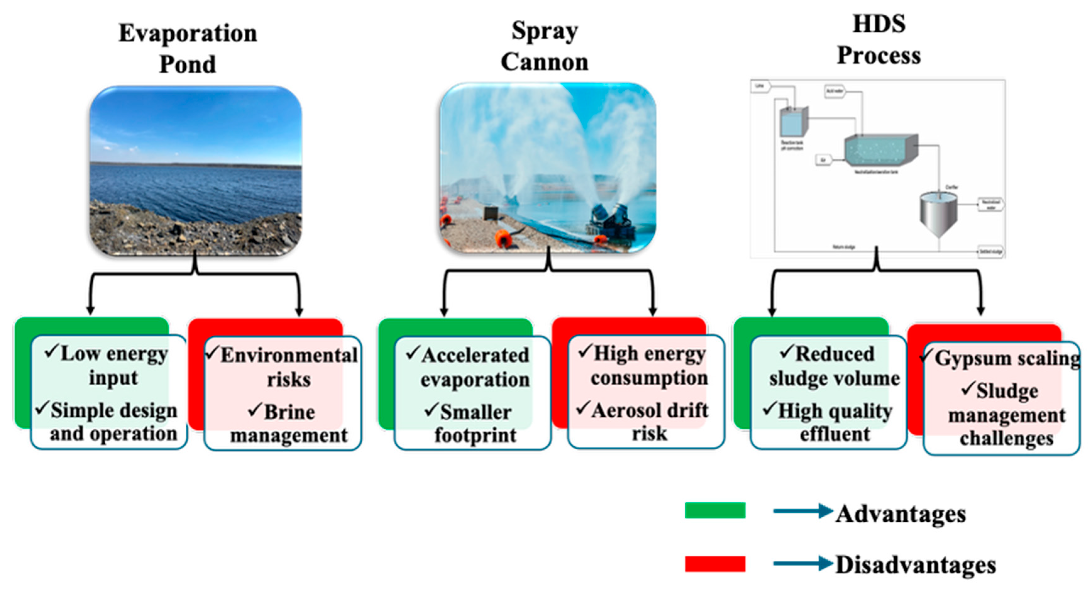
Each conventional approach involves inherent compromises (Figure 1):
  • Biological systems impose minimal environmental impact, but high salinity, extreme pH, and substantial land demand constrain them [34].
  • Chemical methods are reliable and well recognized; however, they generate major sludge volumes with costly disposal requirements [35].
  • Membrane filtration delivers high-purity water, but high expense, fouling susceptibility, and concentrated brine waste are generated [36].
  • Evaporation ponds and cannons are effective, but they are weather-dependent and provide poor control over final effluent quality [30].
A major, commonly overlooked problem is that existing treatment processes emphasize pollutant removal instead of resource recovery; the brine or sludge produced just relocates the pollution burden rather than closing the water loop and yielding valuable products. With mines now targeting ZLD and circular economy models, new treatment approaches must be developed to reclaim clean water and produce saleable by-products [37,38].
Figure 1. Different treatment methods.
Minerals 16 00863 g001

1.4. Waste-Heat-Assisted Pre-Concentration as an Enabling Technology

The pre-concentration of brackish feed streams prior to final treatment is often the most economical option for increasing the financial feasibility of downstream recovery operations. A significant amount of the water can be removed from the system before final concentration, decreasing reactor volume as well as pumping and treatment costs [2,39].
Industrial plants often dispose of vast amounts of low-grade heat in flue gases, exhaust flows and hot process streams. While this heat is typically too low for use in traditional thermal evaporation, it is well suited for low-temperature falling-film evaporation, which can use moderate temperature differences due to the large gas–liquid interface area [40,41].
One promising approach is waste-heat-assisted pre-concentration, where low-grade waste heat from industry is used to evaporate a large fraction of water before downstream processing takes place. By decreasing the hydraulic load, reactor size, and chemical use, and increasing dissolved mineral concentrations, pre-concentration enhances the economics of any downstream resource recovery technology [30,42]. Low-temperature falling-film evaporation is of particular interest because its large gas–liquid interfacial area enables inexpensive waste heat with relatively low temperature to be utilized rather than being vented into the environment [43,44]. The condensed reusable water is generated simultaneously as water is evaporated, while the dissolved salts remain predominantly in the concentrate [2,33]. Since the major dissolved salts are non-volatile, they are expected to remain predominantly in the liquid phase during evaporation, resulting in a condensate with low dissolved-solids content. However, the presence of volatile compounds and aerosols may require mist elimination and, if needed, polishing depending on the feed-water constituents [45,46].

1.5. Integration with Downstream Mineral Recovery

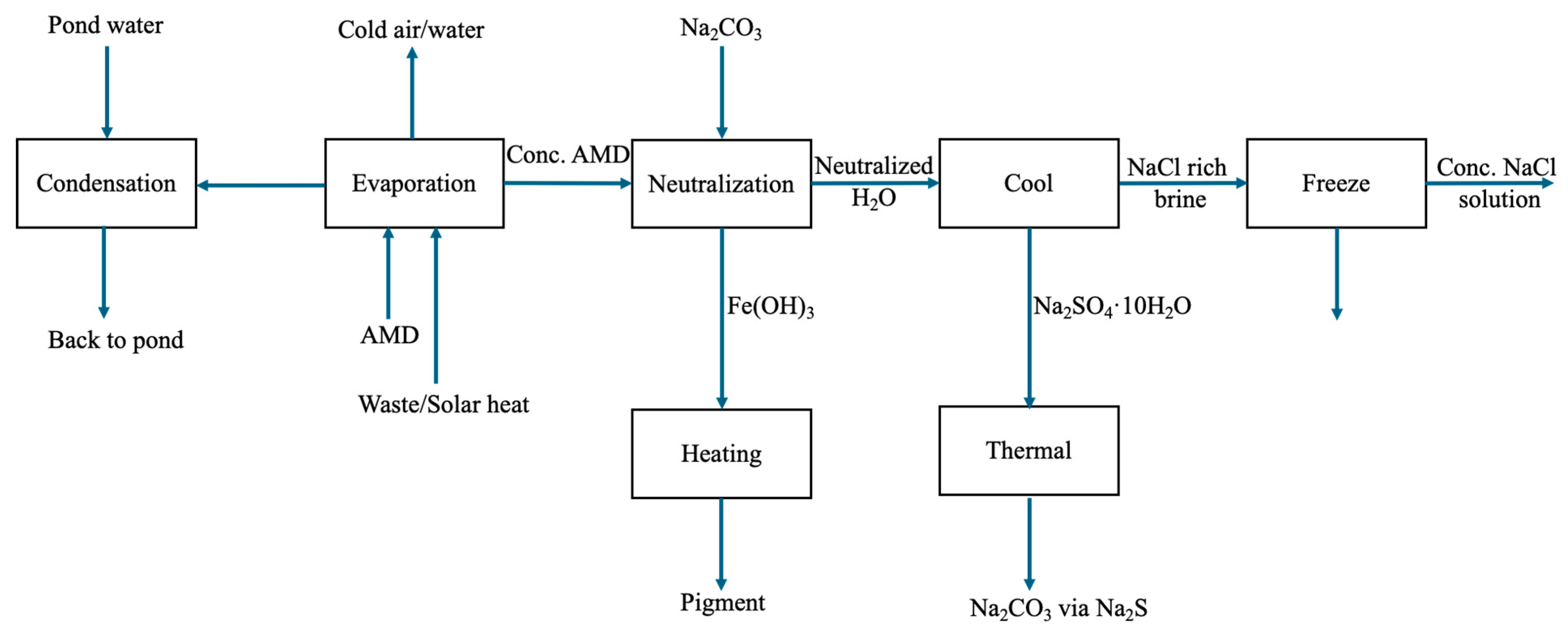
Evaporation has more benefit when coupled to downstream mineral recovery technologies. In mine leachate, evaporation increases dissolved iron levels ahead of chemical precipitation to enable production of iron oxide pigments and magnetite. Evaporation effectively enables production of these materials by operating as a highly efficient pre-concentration step that makes the economics of downstream resource recovery feasible [47,48]. For saline industrial wastewater, evaporation increases the dissolved salt content of the wastewater to levels where freeze crystallization becomes economically viable. Freeze crystallization then enables recovery of potable water as ice plus selective crystallization of valuable salts (e.g., Na2SO4·10H2O, NaCl) [49,50].
Thus, the combined process inherently allows waste-heat integration, water recovery, and mineral recovery all in one circular processing platform that can achieve near-ZLD [51].

1.6. Research Gap

Whilst falling-film evaporation, humidification–dehumidification (HDH), waste-heat utilization, and freeze crystallization have been well researched individually, their application and combination for saline mine-water resource recovery has received limited attention to date [51,52]. Falling-film and HDH research efforts have predominantly been oriented towards heat and mass transfer and water recovery, while waste-heat evaporation studies have focused almost exclusively on evaporation performance measures. In freeze crystallization research, the focus is generally on concentrated feeds, bypassing the development of efficient pre-concentration strategies for dilute saline streams [53]. Moreover, there is not much reported data concerning the collective impacts of operating temperature, airflow, conduit-pipe diameter, pipe material, and heat-transfer prerequisites associated with industrial-scale falling-film reactors used in cycle with waste-heat streams for mineral recovery purposes. This work aims to fill these gaps and benchmark waste-heat-assisted operation against conventional dry-air operation through methodical study of these parameters.

1.7. Objectives

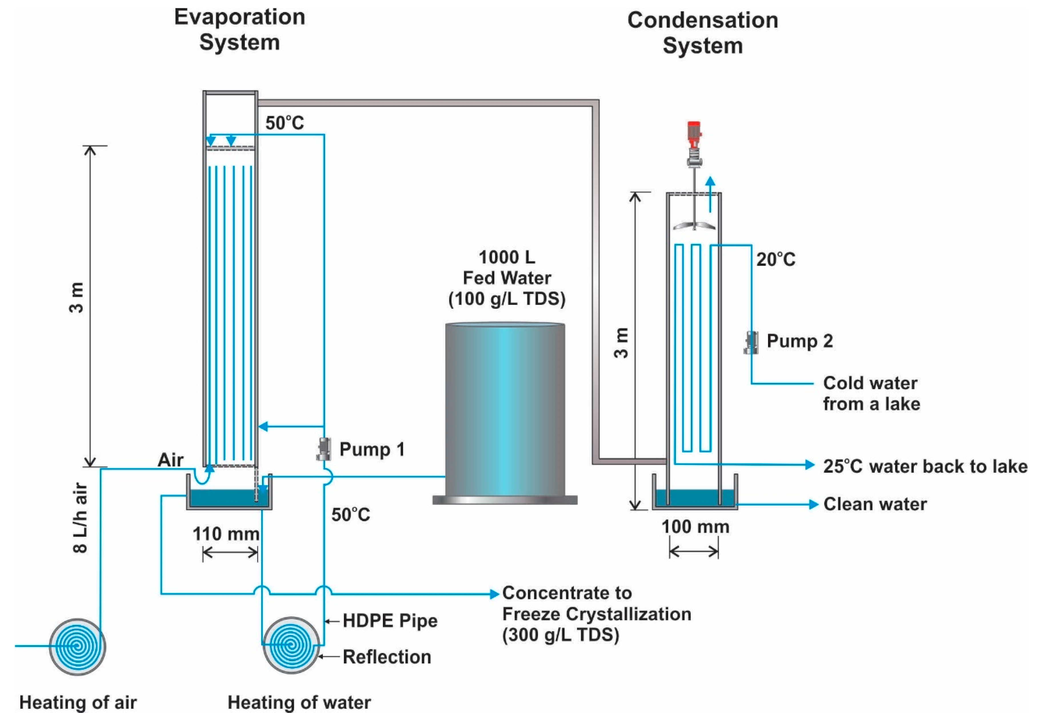
To address the above knowledge gaps and process design objectives, this study designed and assessed the techno-economic potential of a waste-heat-assisted falling-film evaporation reactor (Figure 2) for cost-effective pre-concentration of mine leachate and saline industrial wastewater prior to integrated water and mineral recovery. In detail, the following objectives were addressed:
  • Design, construct, and experimentally evaluate a laboratory-scale waste-heat-assisted falling-film evaporation reactor;
  • Develop and validate a coupled psychrometric and heat-transfer model using the experimental results;
  • Quantify the effects of operating temperature, airflow rate, pipe diameter, column length, and pipe material on reactor performance using the validated model;
  • Compare the technical performance of dry-air and waste-heat-assisted operating strategies;
  • Evaluate the techno-economic feasibility of waste-heat-assisted falling-film evaporation under representative industrial operating conditions;
  • Establish design guidelines for integrating waste-heat-assisted falling-film evaporation into an integrated mine-water resource recovery process.
Figure 2. Concept of proposed evaporation system for dry air.
Minerals 16 00863 g002

1.8. Novelty and Contribution

The innovation of this work is that it designs and assesses a waste-heat-assisted falling-film reactor for use as the first-stage treatment technology of the Circular Industrial Mineral Platform (CIMP). The reactor provides a common pre-concentration stage for two resource-recovery applications: concentration of saline wastewater for subsequent recovery of Na2SO4 and NaCl through crystallization and concentration of iron-rich mine water to facilitate downstream recovery of iron oxide pigments and magnetite. Na2SO4 was selected to represent sulfate-rich wastewater relevant to mine-affected streams, while NaCl represents a highly soluble chloride component of saline wastewater; both are non-volatile and therefore predominantly retained during evaporation, although the temperature-dependent solubility of Na2SO4 may increase precipitation and scaling risks at high concentrations. The study develops a coupled psychrometric and heat-transfer-based design methodology, assesses technical and economic feasibility, evaluates dry-air and waste-heat operating strategies, and demonstrates how pre-concentration can facilitate downstream salt crystallization and selective recovery of iron-containing products. Thus, novelty lies not in evaporation or the individual salts themselves, but in the integrated use of waste-heat-assisted pre-concentration as an enabling stage for circular recovery of both water and valuable mineral products.

2. Process Design and Modelling Methodology

2.1. Process Design Philosophy

The main objective of the above process is not evaporation itself, but rather the low-cost pre-concentration of dilute mine leachate or saline industrial wastewater streams to levels appropriate for downstream processing to recover minerals. Waste-heat-assisted falling-film evaporation is thus a gateway process that enhances dissolved mineral concentration while consuming low-grade heat that would otherwise be discarded to the atmosphere. The resulting concentrated streams can then be further treated to recover valuable minerals through freeze crystallization or selective chemical precipitation. As such, we will refer to pre-concentration throughout this paper as the overall goal of the process, and reserve falling-film evaporation to specifically describe the method of water removal.

2.2. Feed-Water Composition

Two representative feed-water applications were considered. The first comprised a synthetic saline wastewater containing 80 g/L Na2SO4 and 70 g/L NaCl, corresponding to a total dissolved solids concentration of approximately 150 g/L. This composition represents a highly saline industrial wastewater suitable for demonstrating pre-concentration prior to freeze crystallization. During process modelling, the TDS concentration of the saline stream was evaluated over approximately 100–300 g/L to represent the range from relatively dilute conditions through progressive concentration toward the freeze-crystallization stage. The 100, 200, and 300 g/L TDS values shown in the figures therefore represent concentration levels within the modelled process range rather than different feed-water compositions. The experimental synthetic feed had a nominal TDS concentration of approximately 150 g/L.
A second application looked at a typical iron-oxide-rich mine-water feed composition of about 4000 mg/L Fe2+, 95 mg/L Fe3+, 13,000 mg/L acidity as CaCO3, and initial pH~1.7. This composition was selected as a representative feed to assess waste-heat-assisted evaporation as a pretreatment step prior to downstream processes such as neutralization and selective recovery of iron oxide pigments and magnetite. For modelling purposes, it was assumed that dissolved constituents remain in the solution as water is removed, and that downstream chemical reactions and precipitation did not impact the evaporation model. Physical properties such as density and psychrometric properties were computed using standard engineering correlations as a function of temperature and pressure. Effects of pH on evaporation were not modelled for this design exercise as pH effects were assumed negligible; the model described below focuses on heat and mass transfer and does not account for acid–base equilibria.

2.3. Equipment

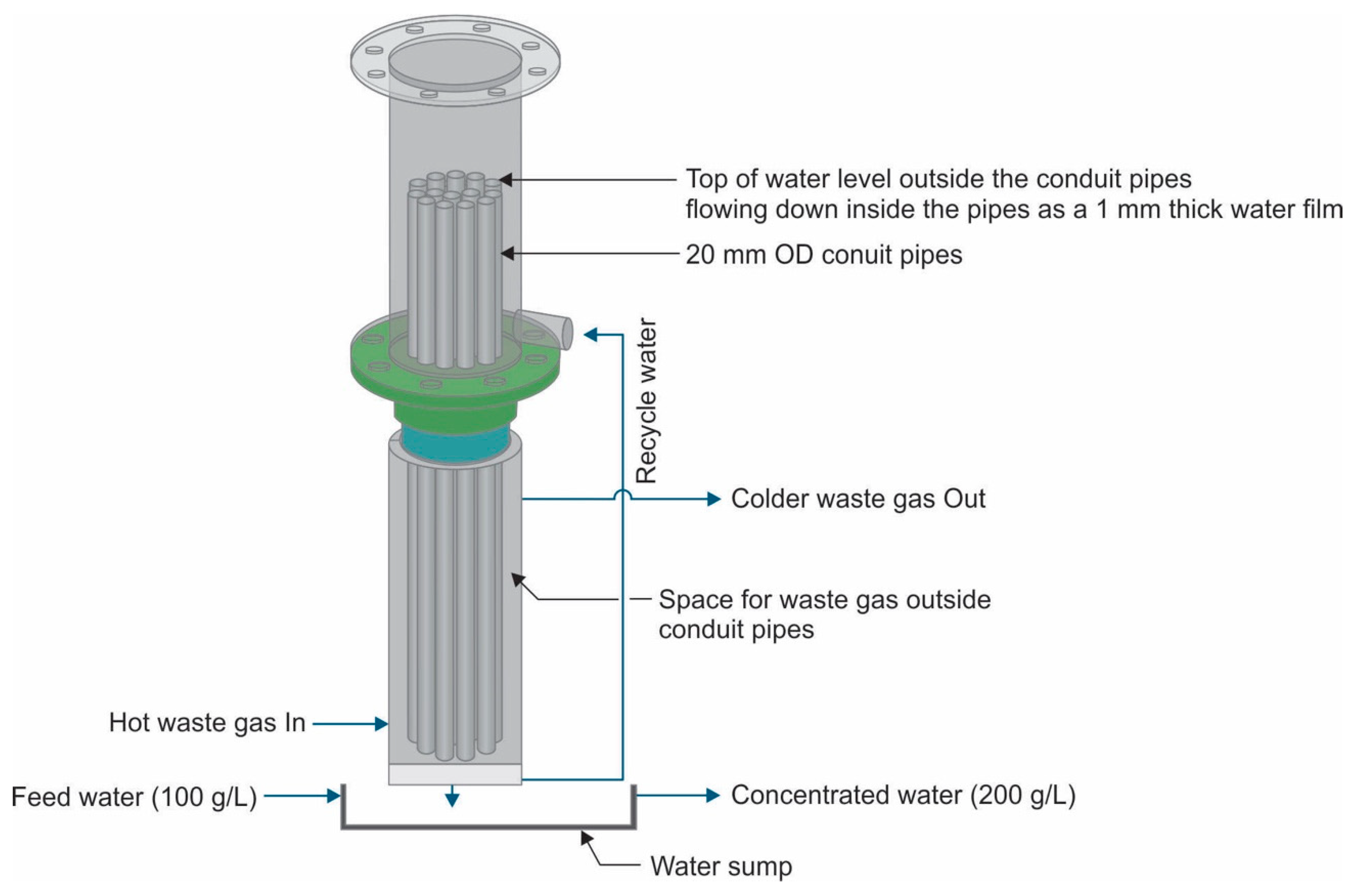
The evaporation reactor consists of a vertical bundle of PVC conduit pipes housed within a larger column (Figure 3). Each conduit pipe (typical dimensions: 3 m length, 20 mm outer diameter, 17 mm inner diameter) serves as an individual evaporation channel. The number of pipes represents the total number of individual conduit pipes required to provide the calculated heat-transfer area, while the number of rings represents the number of circumferential arrangements of pipes within the reactor.
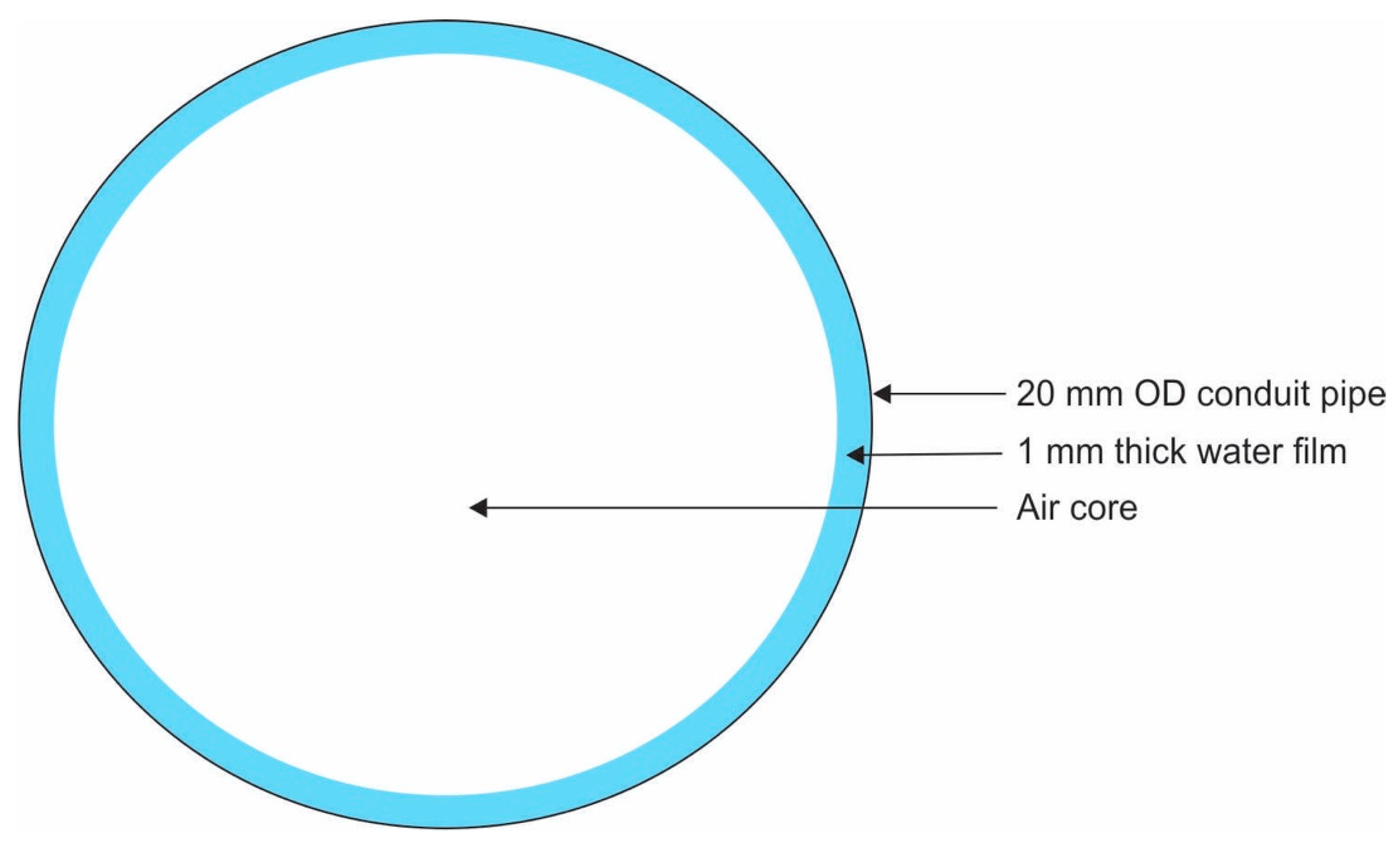
Saline water flows downward along the inner wall of each pipe as a thin falling film, while dry air flows through the central core of the pipe (Figure 4). Heating is provided indirectly by bypassing warm air or waste gas through the annular space surrounding the conduit pipes. The calculated number of pipes represents the theoretical requirement and may therefore be non-integer; for practical reactor construction, the value is rounded up to the nearest whole number.
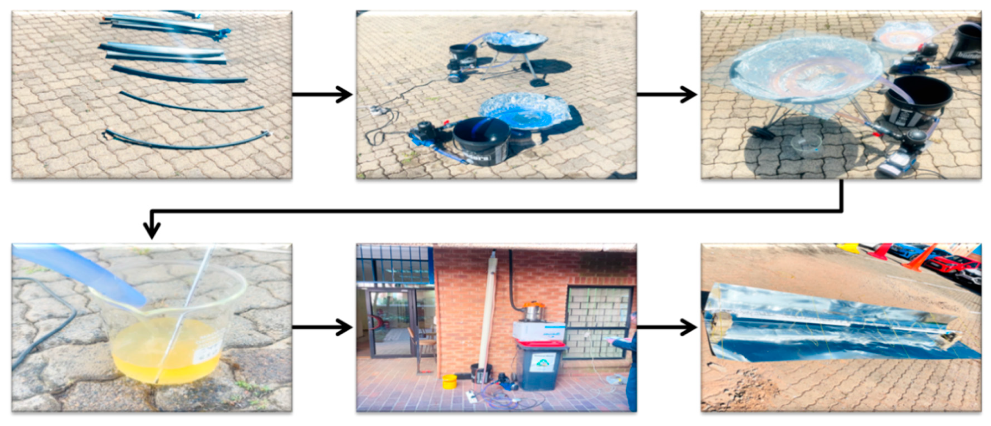
Prior to mathematical modelling, a series of heating experiments was conducted to evaluate the influence of conduit-pipe diameter, heating configuration, and solar collectors on water-heating performance (Figure 5).

2.4. Experimental Heating Studies and Model Input

Heating tests were conducted to examine how variables such as pipe/conduit diameter, heating arrangement, glass cover, water circulation, and flow rate influence the water-heating performance. Temperatures of the water and ambient air were measured at consistent time intervals during testing of each configuration. The resulting temperature–time data were used to compare the heating performance of the tested configurations and select the most suitable pipe diameter and operating configuration for the evaporation system. The experimentally selected pipe configuration and measured heating performance were then incorporated into the mathematical model as the pipe geometry and water-side temperature boundary condition, respectively. These experimentally derived inputs provided realistic operating conditions for the subsequent heat- and mass-transfer calculations. The model was then used to evaluate the falling-film evaporation system under waste-heat-assisted operation and compared with a baseline dry-air case without industrial waste heat. This comparison was used to quantify the effect of waste-heat integration on airflow requirement, heat transfer, and evaporation performance.

2.5. Psychrometric Modelling

Moisture transfer between the falling liquid film and the surrounding air was measured using psychrometric modelling. The mass balance of water vapour in the air stream was used to calculate the evaporation rate:
m ˙ H 2 O = m ˙ a i r ( w o u t w i n )
where m ˙ H 2 O is the evaporation rate (kg/h), m ˙ a i r is the dry air mass flow rate (kg/h), and w o u t and w i n are the outlet and inlet humidity ratios (kgH2O/kg dry air), respectively.
Psychrometric properties including humidity ratio, saturation humidity ratio, and enthalpy were calculated for various operating temperatures and ambient conditions. The calculations performed were used to assess the moisture-carrying capacity of the air stream and determine the influence of temperature and airflow conditions on the evaporation efficiency of the reactor.

2.6. Heat-Transfer Modelling

Heat transfer in the system was modelled using an overall energy balance between the air and the liquid film. The rate of heat transfer was calculated using
Q = U A Δ T L M
where Q is the total heat-transfer rate (kW), U is the overall heat-transfer coefficient (W·m−2·K−1), A is the heat-transfer surface area (m2), and Δ T L M is the logarithmic mean temperature difference (K).
The model includes convective heat transfer from the air, conductive resistance through the pipe wall, and interfacial heat transfer to the liquid film. The influence of different pipe materials was assessed by including the heat conductivity of the material.

2.7. Heat-Flux Feasibility Evaluation

Heat-flux feasibility was assessed by comparing the available thermal energy to the required energy for evaporation. Heat flux was defined as
q = Q A
where q″ is the heat flux (kW/m2), Q is the total heat-transfer rate (kW), and A is the effective heat-transfer surface area (m2). The system was considered thermally feasible when q a v a i l a b l e q required , and the heat flux margin (which was presented by q a v a i l a b l e q required ) was used to determine the design strength.

2.8. Energy Feasibility Evaluation

An energy balance was performed to evaluate the total energy requirement for phase change. The evaporation energy demand was calculated as
Q = m ˙ e v a p λ
where m ˙ e v a p is the evaporation mass flow rate (kg/s) and λ is the latent heat of vaporization (kJ/kg). The total energy demand included
  • latent heat of evaporation,
  • sensible heating of the feed,
  • thermal losses.
The available energy from waste heat and ambient air was compared with the required energy to determine process feasibility.

2.9. Pipe Material Comparison

The effect of conduit-pipe material on reactor performance was evaluated by comparing PVC and stainless steel under identical operating conditions. The comparison focused on
  • thermal conductivity,
  • heat-transfer performance,
  • evaporation capacity,
  • capital cost.
Corrosion resistance and long-term durability were not included in the current analysis.

2.10. Feasibility and Cost Evaluation

A techno-economic assessment was conducted to determine the practicality of the proposed evaporation system. Capital costs included
  • conduit pipes,
  • reactor shell,
  • pumps,
  • fans,
  • support structures.
Operating costs included
  • electrical power consumption,
  • maintenance,
  • component replacement.
The economic performance of each design was evaluated using
  • capital cost per unit evaporation capacity,
  • operating cost per cubic metre of water evaporated,
  • overall feasibility for industrial implementation.
The combined technical and economic analyses were used to identify the most practical reactor configuration for saline-water concentration and subsequent resource recovery.

2.11. Integration with Mineral Recovery

The proposed evaporation reactor is intended to operate as the first stage of an integrated mineral recovery process.
For saline industrial wastewater, evaporation increases dissolved salt concentrations to levels suitable for freeze crystallization, enabling selective recovery of sodium sulphate decahydrate (Na2SO4·10H2O), sodium chloride and high-purity water.
For mine leachate, evaporation increases dissolved iron concentrations before downstream chemical treatment, thereby facilitating recovery of iron oxide pigments and magnetite.
Accordingly, the falling-film evaporation reactor should be regarded as a waste-heat-assisted pre-concentration technology that enhances the technical and economic feasibility of downstream mineral recovery rather than as an isolated wastewater treatment process.

3. Results and Discussion

3.1. Waste-Heat-Assisted Falling-Film Evaporation

The results reported here establish metrics for assessing the effectiveness and practicality of coupling waste heat to the falling-film evaporation process for saline/mine water pre-concentration. Both the thermal driving requirement for evaporation and the impact of the available waste-heat stream upon reactor operating/enforcing conditions and design are considered. In particular, the impact of waste-gas temperature/flow, as well as conduit-pipe diameter/material/heat-transfer properties on evaporation performance, is quantified. These results form the basis for determining the practicality of waste heat-assisted evaporation pre-concentration as part of the proposed process.

3.1.1. Effect of Conduit-Pipe Diameter

Conduit-pipe diameter is one of the most important design variables because it simultaneously influences heat-transfer area, reactor compactness, and construction cost. Table 1 presents the effect of pipe diameter on the thermal feasibility of the evaporation system under constant operating conditions. The results clearly demonstrate that pipe diameter is a critical parameter governing the balance between heat-transfer capability and system compactness.
For smaller pipe diameters (12 mm and 20 mm), the available heat flux exceeds the required heat flux:
q a v a i l a b l e q r e q u i r e d > 0
This indicates that sufficient heat can be transferred through the pipe wall to sustain evaporation at the design rate of 100 L/h. This is primarily because of the high surface area-to-volume ratio, which improves heat transfer. However, pipes with large diameters (50 mm and 110 mm) show negative values:
q a v a i l a b l e q r e q u i r e d < 0
This indicates that the available heat flux is not enough to meet the evaporation demand. Even if a large-diameter pipe significantly decreases the number of pipes required (from approximately 635 to fewer than 3 pipes), they also decrease the effective heat-transfer area per unit volume and increases thermal resistance effects.
These results highlight a fundamental design trade-off:
  • Large pipes lead to a compact reactor, fewer pipes, but poor heat transfer,
  • Small pipes lead to higher pipe count, but thermally feasible operation.
This behaviour confirms that, under waste heat conditions, the system is heat-transfer limited, and that smaller diameters are preferred despite increased structural complexity.

3.1.2. Effect of Column Length

Column length determines both the available heat-transfer surface area and the residence time available for heat exchange. Increasing column length therefore increases the total quantity of heat transferred to the falling liquid film without altering the operating temperature. Table 2 shows the effect of column (pipe) length on heat-transfer performance at fixed operating conditions. At a column length of 2 m, the system exhibits a large heat deficit:
q a v a i l a b l e q r e q u i r e d = 2.92   kW / m 2
Increasing the length to 4 m improves heat transfer:
q a v a i l a b l e q r e q u i r e d = 0.62   kW / m 2
But the system remains thermally constrained. At 6 m, the system becomes feasible:
q a v a i l a b l e q r e q u i r e d = + 0.14   kW / m 2
This behaviour reflects the direct relationship between column length and total heat-transfer area:
A H T = N π D o H
Thus, increasing column length increases the heat-transfer area, which increases the residence time for heat exchange and enhances overall heat-transfer performance. From a design perspective, column length can be used as a make-up variable to overcome heat-transfer shortcomings when temperature is fixed. Nevertheless, increasing length also creates practical constraints such as additional structural requirements and increased pressure drop.
For the present design, a column length of approximately 6 m provides an effective balance between thermal performance and mechanical practicality.

3.1.3. Effect of Waste Heat

The temperature of the waste-gas stream controls the thermal driving force available for evaporation and therefore represents the principal operating variable in externally heated systems. Table 3 shows the influence of waste gas inlet temperature on system performance at a constant pipe diameter of 20 mm. At a waste gas temperature of 90 °C, the heat flux deficit is significant:
q a v a i l a b l e q r e q u i r e d = 0.61   kW / m 2
This indicates that the available temperature driving force is insufficient to sustain evaporation at 60 °C. Increasing the inlet temperature to 120 °C reduces the deficit:
q a v a i l a b l e q r e q u i r e d = 0.17   kW / m 2
This shows that there is improved heat transfer, even though the system remains thermally infeasible. At a temperature of 144.1 °C, the system becomes thermally feasible:
q a v a i l a b l e q r e q u i r e d = + 0.14   kW / m 2
This shows that the temperature of the waste heat is one of the most important variables in the design, because it directly controls the temperature driving force (ΔT) and thereafter the available heat flux. In practical terms, a minimum waste heat temperature is needed to meet the heat flux constraints. If the inlet temperature drops below this value, increasing surface area and air flow rate alone cannot overcome the reduced thermal driving force.
For the 20 mm, 6 m geometry evaluated here, increasing the waste-gas inlet temperature from 90 to 120 °C moves the reactor toward feasibility, whereas approximately 144 °C provides a positive local heat-flux margin. The required temperature is therefore geometry- and material-specific rather than a universal operating range.

3.1.4. Energy Feasibility Versus Heat-Transfer Feasibility

Table 4 presents the feasibility assessment for the selected 12 mm-diameter conduit configuration comparison between energy feasibility and heat-transfer feasibility, highlighting an important design insight.
In both cases of using waste heat temperatures (90 °C and 144.1 °C), they satisfy the energy balance:
Q a v a i l a b l e Q r e q u i r e d
Nevertheless, the heat flux margins differ considerably:
At 90 °C:
q a v a i l a b l e q r e q u i r e d = 0.34   kW / m 2
At 144.1 °C:
q a v a i l a b l e q r e q u i r e d = 1.07   kW / m 2
For the 12 mm, 6 m conduit configuration, waste gas entering at 90 °C provides a positive local heat-flux margin of 0.34 kW/m2, but the available thermal energy (19.17 kW) is substantially below the calculated heating requirement (79.78 kW). The 90 °C case is therefore heat-transfer feasible locally but energy infeasible overall.
At 144.1 °C, the available energy increases to 114.27 kW and the local heat-flux margin to 1.07 kW/m2; both feasibility criteria are satisfied. This confirms that a positive heat-flux margin alone does not establish overall process feasibility.
Conversely, an adequate overall energy balance would not guarantee continuous evaporation if the available local heat flux were insufficient. Robust reactor design must therefore satisfy both the overall energy balance and the local heat-transfer criterion simultaneously.
Once both criteria are satisfied, an additional positive design margin is desirable to accommodate fouling, scaling, heat losses, and flow maldistribution during long-term operation.
The feasibility of the evaporation system was evaluated using two independent parameters, namely (i) heat-transfer feasibility based on the available heat flux, and (ii) overall energy feasibility based on the available thermal energy in the gas stream.

3.1.5. Pipe Material

Table 5 compares the performance of PVC and steel conduit pipes on the evaporation reactor under similar conditions. In comparison to the freeze crystallization process, where the thermal conductivity of a pipe material strongly affects heat transfer, it shows that the number of pipes required for evaporation has a small difference between the materials. This is because in evaporation systems, the process is managed mainly by air-side mass transfer and large airflow rates, rather than increased heat conduction through the pipe wall. The results show that
(i)
Steel pipes have high thermal conductivity, >45 W/m·K; it provided a positive heat-flux margin ( q a v a i l a b l e q r e q u i r e d = 0.29 kW/m2), meeting the heat-transfer criterion.
(ii)
PVC pipes have low conductivity, approximately 0.19 W/m·K; they yielded a slightly negative margin ( q a v a i l a b l e q r e q u i r e d = 0.49 kW/m2), operating just below the required flux.
The relatively small difference between the two materials indicates that evaporation performance is controlled primarily by air-side mass transfer and the availability of thermal energy rather than by conduction through the pipe wall. Therefore, increasing thermal conductivity provides only a modest improvement in overall reactor performance.
These results suggest that PVC conduit pipes may be a practical and economical option where sufficient heat-transfer area and airflow are available, while steel conduit pipes provide additional design flexibility and larger heat-transfer safety margins under more demanding operating conditions.
An important consideration is the ability of PVC conduit pipes and the outer reactor shell to withstand elevated waste-gas temperatures (100 to 150 °C). Although standard PVC is generally recommended for continuous service below approximately 60 to 70 °C, the conduit pipes in the evaporation reactor are continuously cooled by the falling water film on the inner surface. The latent heat associated with evaporation removes a significant portion of the transferred thermal energy, thereby maintaining the conduit wall temperature close to the evaporation temperature (approximately 60 °C) rather than the waste gas temperature.
This occurrence is comparable to the well-known demonstration in which a plastic bag containing water can be exposed to a flame without melting because the water rapidly removes the incoming heat. Similarly, the falling water film acts as an effective heat sink that limits the temperature rise in the conduit wall.
Nevertheless, localized overheating may occur if liquid distribution becomes non-uniform, if portions of the wall become dry, or if excessive waste gas temperatures are applied. The outer reactor shell is particularly vulnerable because it is not cooled directly by the water film. For pilot-scale systems operating at moderate temperatures, PVC appears suitable provided that continuous wetting of the conduit pipes is maintained. For industrial-scale applications and long-term operation at elevated temperatures, alternative materials such as HDPE, fibre-reinforced polymer (FRP), stainless steel, or insulated metallic shells should be considered to improve reliability and service life.
The economic implications of these material choices will be considered at industrial scale, where the higher capital cost of corrosion-resistant materials can be weighed against their expected service life and reduced corrosion-related maintenance and replacement.

3.1.6. Integrated Interpretation

An evaporation system that is heated externally is mostly limited by heat-transmission limitations, rather than by the energy only which is available. The findings show that
  • Pipe diameter controls local heat-transfer intensity;
  • Waste heat temperature controls driving force (ΔT);
  • Column length controls total heat-transfer area;
  • Energy availability alone is not sufficient for design validation.
This leads to a clear engineering principle that evaporation feasibility requires both:
Q a v a i l a b l e Q r e q u i r e d and   q a v a i l a b l e q r e q u i r e d
Failure to satisfy the second condition results in underperforming systems, even when sufficient energy is available.

3.2. Convectional Dry-Air Evaporation as an Engineering Benchmark

The waste-heat-assisted reactor presented in Section 3.1 is the design concept ultimately favoured for industrial application in this work. However, dry-air evaporation serves as a convenient engineering point of reference by exposing the inherent psychrometric limits of evaporation without the benefit of an external heat source. This comparison also forms a baseline for solar-assisted pre-concentration designs which use solar energy instead of industrial waste heat. Unlike the waste-heat-assisted reactor, where evaporation is governed primarily by heat transfer through the conduit wall, dry-air evaporation is controlled almost entirely by the moisture-carrying capacity of the air. Consequently, the design variables influencing reactor performance differ substantially from those discussed in Section 3.1.

3.2.1. Effect of Dry Air Temperature

Operating temperature is the dominant design variable under dry-air operation because it determines the psychrometric capacity of the air to absorb water vapour. Increasing the inlet air temperature increases the saturation humidity ratio and therefore increases the amount of water that can be evaporated by each conduit pipe. The relationship is described by the equation below:
m ˙ H 2 O = m ˙ a i r Δ w
where the evaporation rate ( m ˙ H 2 O ) is equal to the dry-air mass flow rate multiplied by the increase in humidity ratio (Δw). For a fixed evaporation target of 100 L/h, increasing the inlet air temperature increases Δw, thereby reducing the dry-air flow rate required to remove the same quantity of water.
The modelling results in Table 6 demonstrate that increasing the inlet air temperature from approximately 26 °C to 40 °C substantially increases the evaporation capacity per conduit pipe while reducing the number of pipes required to achieve the design evaporation rate of 100 L/h. At 40 °C, approximately 2150 conduit pipes are required, whereas operation near ambient conditions (26 °C) requires more than 30,000 pipes. Even at 60 °C, approximately 922 pipes remain necessary.
Although reactor size decreases rapidly with increasing temperature, the airflow requirement remains very large. At approximately 40 °C, it requires 13,682 m3/h of dry air, while operation near ambient conditions requires 205,212 m3/h. These airflow requirements result in large fans, extensive ducting, and high electrical power consumption.
Consequently, the principal limitation of dry-air evaporation is not heat transfer but the limited moisture-carrying capacity of air under near-ambient conditions.

3.2.2. Effect of Conduit-Pipe Diameter

In this section, the effect of pipe diameter on the performance of evaporation was evaluated by varying the internal conduit diameter while sustaining constant air velocity. The results show that the increase in pipe diameter leads to a substantial decrease in the number of pipes needed, while the overall reactor diameter remains nearly constant.
Mechanistic Interpretation
In the configuration of dry air, evaporation is primarily controlled by the mass flow rate of dry air passing through the pipe; then the evaporation rate per pipe is directly proportional to the air flow rate represented by the equation below:
m ˙ H 2 O m ˙ a i r Δ w
Since the equation for air flow per pipe is written as
V ˙ a i r = A V D 2
It now means that (i) increasing pipe diameter increases air core area ( A D 2 ), (ii) increased air flow per pipe leads to higher evaporation capacity per pipe, and this results in the number of pipes decreasing approximately with 1 / D 2 . This explains the large reduction in the number of pipes in Table 7.
Limited Effect on Reactor Diameter
Even though there is a decrease in the number of pipes, the total reactor diameter increases only slightly. This is because of the balancing relationship:
A r e a c t o r N D o 2
Since
N 1 D 2 , D o 2 D 2
The two effects offset each other, resulting in an approximately constant reactor cross-sectional area. This is a critical and non-intuitive design insight showing that increasing pipe diameter improves capacity without significantly increasing reactor size.
Hydrodynamic Considerations
The anticipated falling-film thickness of 1 mm confirms continuous renewal of the liquid interface and stable gravitational flow. From the observed conditions: (i) gas-side mass transfer is leading, liquid-side resistance is insignificant, and (ii) interfacial balance is approached quickly. This confirms the idea that the evaporation rate is governed by the volume of air rather than interfacial kinetics. However, at large diameters, second-order effects may become significant (film instability and stream formation, maldistribution of liquid, and reduced interfacial area per unit volume), and these factors may limit scaling up and should be taken into consideration in a detailed design.
Engineering Interpretation and Design Implication
The results shown in Table 7 confirm the following key engineering points:
  • Temperature sensitivity: evaporation performance is highly sensitive to temperature, with a small increase in air temperature resulting in a substantial reduction in the required reactor size.
  • Mass-transfer-controlled system: the process is primarily controlled by the moisture-carrying capacity of the air rather than heat transfer, which limits the effectiveness of dry-air operation.
  • Pipe-diameter optimization: increasing the pipe diameter considerably reduces the number of pipes required while maintaining a similar reactor footprint, thereby improving mechanical simplicity and reducing potential costs.
  • Airflow requirement: very large volumetric airflows are required, resulting in high fan-power demand, large ducting requirements, and increased operating costs.
Overall, the analysis shows that although dry-air evaporation is technically feasible, it is not economically attractive because of the high airflow requirements, low energy efficiency, large number of pipes, and associated mechanical and electrical demands. These limitations indicate that dry-air evaporation alone is unlikely to be practical for industrial-scale application and motivate the integration of solar thermal energy and industrial waste heat to increase the air temperature and improve the overall performance of the system.

3.3. Feasibility Analysis of the Comparative Evaluation of Evaporation with Dry Air Versus Waste Heat

Table 8 presents a comparative evaluation of two evaporation configurations, namely (i) evaporation using dry air only, and (ii) direct utilization of waste heat within the evaporation reactor.

3.3.1. Dry Air Process

The dry air configuration (Table 8) is governed primarily by the psychrometric capacity of air. At an inlet temperature of 40 °C, the moisture carrying capacity of air is limited, resulting in a relatively low evaporation rate per pipe (0.0465 L/h). Consequently, many pipes (approximately 2150) and high air flow rates (approximately 13,700 m3/h) are required. This leads to high fan and pump power requirements and, therefore, high operating costs.
The results confirm that evaporation in this configuration is mass transfer controlled, with negligible contribution from heat transfer through the pipe wall. As a result, pipe diameter has a limited effect on reactor size, while air temperature is the dominant design parameter.

3.3.2. Direct Waste Heat Process

The direct waste heat configuration (Table 8) is fundamentally different, as evaporation is governed by heat transfer through the pipe wall. The use of high-temperature waste gas (144 to 80 °C) allows evaporation at elevated temperatures (60 °C), significantly increasing the evaporation rate per pipe (0.157 L/h). This results in a much smaller number of pipes (approximately 635) and a compact reactor (approximately 0.42 m diameter).
An additional benefit is the recovery of approximately 156 kg/h of clean condensate through cooling of the water-saturated waste gas. This improves overall water recovery and enhances process sustainability.

3.3.3. Overall Comparison and Implications

The results in Table 8 demonstrate that direct utilization of waste heat provides the most attractive design option from both technical and economic perspectives. Relative to the dry air configuration, the waste heat configuration reduces
  • Number of pipes by approximately 70%;
  • Reactor diameter by approximately 65%;
  • Airflow requirement by approximately 94%;
  • Electrical power demand by approximately 88%;
  • Capital cost by approximately 84%.
Although the waste-heat configuration is more dependent on heat-transfer performance and pipe-wall thermal resistance, the substantial reduction in airflow and equipment size outweighs these limitations. The dry-air configuration remains technically feasible and may be attractive in regions with abundant warm, dry air, but its large airflow requirement significantly increases both capital and operating costs.
Overall, the results confirm that direct utilization of industrial waste heat represents the preferred evaporation strategy for large-scale saline-water concentration and resource recovery applications.


4. Integrated Engineering Design Methodology

The design analyses in Section 3 can be consolidated into a practical engineering methodology for waste-heat-assisted falling-film pre-concentration. Table 9 translates the modelling results into a sequence of engineering questions, design variables, governing principles and design recommendations. It therefore provides the link between the detailed reactor calculations and the broader CIMP engineering design platform.
The table shows that reactor optimization cannot be based on a single variable. Conduit diameter and column length determine available heat-transfer area; waste-gas temperature determines the thermal driving force and overall energy availability; conduit material affects the heat-flux margin and durability; and the final configuration must also minimize airflow, electrical demand, reactor footprint, and cost. Most importantly, both the overall energy balance and the local heat-transfer criterion must be satisfied simultaneously.

5. Conclusions

A thin-film air-core evaporation reactor was evaluated for the treatment of mine leachate and saline industrial wastewater using coupled psychrometric, heat-transfer, and mass-transfer modelling. The reactor was assessed under a range of operating temperatures, airflow rates, pipe diameters, pipe materials, and waste-heat conditions to identify practical operating windows for large-scale implementation. The major findings of the study are as follows:
  • Waste-heat-assisted falling-film evaporation demonstrated potential for pre-concentrating saline industrial wastewater and mine leachate under the investigated operating conditions.
  • Under dry-air operation, evaporation was primarily limited by the psychrometric capacity of the air. Consequently, very high airflow rates and reactor sizes were required for the investigated evaporation capacity.
  • Integration of industrial waste heat substantially reduced the required airflow from approximately 205,000 m3/h to 880 m3/h for an evaporation capacity of 100 L/h. Waste-gas temperatures of approximately 120–145 °C provided feasible operating conditions based on the combined heat-transfer and energy-balance criteria.
  • Reactor optimization demonstrated that conduit-pipe diameter, column length, waste-gas temperature, and heat-transfer feasibility must be considered simultaneously. Satisfying the overall energy balance alone was insufficient; adequate local heat-transfer capability was also required for continuous evaporation.
  • The results indicated that reactor performance was governed predominantly by air-side heat and mass transfer. Therefore, conduit-pipe thermal conductivity had a smaller influence on overall performance under the investigated conditions, supporting the use of corrosion-resistant PVC conduit pipes as a practical design option.
  • Waste-heat integration reduced the estimated capital cost by approximately 85% and substantially reduced the required airflow and reactor footprint compared with the dry-air configuration.
  • The modelling results demonstrate the technical potential of waste-heat-assisted falling-film evaporation as a pre-concentration step for saline and mine-affected waters. Downstream freeze crystallization and chemical recovery were identified as potential subsequent processes but were not experimentally investigated in this study.
  • Overall, the study provides a model-based engineering assessment of waste-heat-assisted falling-film evaporation and establishes operating and design considerations for its application as a wastewater pre-concentration process.

6. Industrial Implications and the Circular Industrial Mineral Platform (CIMP)

The greatest benefit of the proposed evaporation reactor is achieved when it is integrated with freeze crystallization as part of a hybrid water recovery process (Figure 6). The two technologies operate in complementary concentration ranges and address different limitations associated with saline water treatment.
Evaporation is highly effective for removing large quantities of water using low-grade solar energy or industrial waste heat. By reducing the feed volume and increasing salt concentration, evaporation substantially decreases the hydraulic load on downstream treatment processes. However, as salinity increases, scaling, corrosion, and osmotic effects progressively reduce process efficiency.
Freeze crystallization becomes increasingly attractive at high salinity because the energy required to form ice is significantly lower than that required to evaporate water. In addition, freeze crystallization enables selective recovery of valuable salts such as sodium sulphate decahydrate (Na2SO4·10H2O) while simultaneously producing high-purity ice that can be melted to generate reusable water.
The combination of evaporation and freeze crystallization therefore provides several advantages:
  • Significant reduction in wastewater volume through evaporation,
  • Efficient treatment of highly concentrated brines through freeze crystallization,
  • Recovery of valuable salts such as sodium sulphate decahydrate,
  • Production of high-quality water from melted ice,
  • Reduced overall energy consumption compared with stand-alone evaporation,
  • Improved economics through resource recovery and reduced waste-disposal costs,
  • Progress toward zero-liquid-discharge (ZLD) operation.
The results indicate that evaporation should be viewed primarily as a pre-concentration step, while freeze crystallization serves as the final water- and salt-recovery stage. The integration of these technologies offers a promising route for sustainable treatment of mine leachate and saline industrial wastewater and represents one of the most significant contributions of the present study.

7. Highlights

  • A falling-film reactor using industrial waste heat was developed for saline-water pre-concentration.
  • Waste heat reduced airflow requirements from approximately 205,000 to 880 m3 h−1.
  • Reactor diameter decreased from 4.58 m to less than 0.5 m.
  • Evaporation provides an economical pre-concentration step prior to freeze crystallization.
  • The integrated process enables recovery of water, sodium sulphate, sodium chloride, and iron-based mineral products.

Author Contributions

Conceptualization, data curation, formal analysis, investigation, methodology, software, writing—original draft preparation: M.G.R.; data curation, formal analysis, funding acquisition, investigation, methodology, resources, software, supervision, validation, writing—review and editing: J.P.M. writing—review and editing, validation, investigation, resources: T.A.M.M. All authors have read and agreed to the published version of the manuscript.

Funding

Mokgadi Rapeta received financial support from the National Research Foundation (NRF). This study is also based on research funded by the Department of Trade and Industry (DTI) under the Technology and Human Resources for Industry Programme (THRIP/23/04/05/2023).

Data Availability Statement

The original contributions presented in this study are included in the article. Further inquiries can be directed to the corresponding authors.

Acknowledgments

The authors express their gratitude to THRIP, MAMDIWAS, and the University of South Africa (UNISA) Institute of Nanotechnology and Water Sustainability for research facilities. During the preparation of this manuscript, the authors used [Microsoft Copilot (2026) and Writefull for Word] for the purposes of language editing, improvement of clarity, and verification of standard engineering calculations. The authors have reviewed and edited the output and take full responsibility for the content of this publication.

Conflicts of Interest

The authors declare no conflict of interest.

References

  1. Harding, G.E. Developing Methods to Access Sensitive Industrial Wastewater Information in South Africa (with Treatment in Mind). Master’s Thesis, University of Cape Town, Cape Town, South Africa, 2018. [Google Scholar]
  2. Pervov, A.; Aung, H.Z.; Spitsov, D. Treatment of mine water with reverse osmosis and concentrate processing to recover copper and deposit calcium carbonate. Membranes 2023, 13, 153. [Google Scholar] [CrossRef] [Scilit] [PubMed]
  3. Lee, S.; Choi, J.; Park, Y.-G.; Shon, H.; Ahn, C.H.; Kim, S.-H. Hybrid desalination processes for beneficial use of reverse osmosis brine: Current status and future prospects. Desalination 2019, 454, 104–111. [Google Scholar] [CrossRef] [Scilit]
  4. Mitko, K.; Turek, M. Membrane-based solutions for the Polish coal mining industry. Membranes 2021, 11, 638. [Google Scholar] [CrossRef] [Scilit] [PubMed]
  5. Hernández, K.; Muro, C.; Monroy, O.; Diaz-Blancas, V.; Alvarado, Y.; Diaz, M.d.C. Membrane water treatment for drinking water production from an industrial effluent used in the manufacturing of food additives. Membranes 2022, 12, 742. [Google Scholar] [CrossRef] [Scilit] [PubMed]
  6. Ryu, S.; Naidu, G.; Johir, M.A.H.; Choi, Y.; Jeong, S.; Vigneswaran, S. Acid mine drainage treatment by integrated submerged membrane distillation–sorption system. Chemosphere 2019, 218, 955–965. [Google Scholar] [CrossRef] [Scilit] [PubMed]
  7. Stoica, C.; Dinu, L.R.; Lucaciu, I.E.; Oncu, V.; Gheorghe, S.; Nita-Lazar, M. Sensitivity of pathogenic bacteria strains to treated mine water. Int. J. Environ. Res. Public Health 2022, 19, 15535. [Google Scholar] [CrossRef] [Scilit] [PubMed]
  8. Wang, M.; Wei, Y.; Li, R.; Wang, X.; Wang, C.; Ren, N.; Ho, S.-H. Sustainable seawater desalination and energy management: Mechanisms, strategies, and the way forward. Research 2023, 6, 0290. [Google Scholar] [CrossRef] [Scilit] [PubMed]
  9. Thampan, D.; Karthika, S.; Ravichandran, M.K.; Subramanian, A.; Nagarajan, A.M.; Hussain, R.; Sivagami, K. Emerging investigator series: A state-of-the-art review on large-scale desalination technologies and their brine management. Environ. Sci. Water Res. Technol. 2025, 11, 167–195. [Google Scholar] [CrossRef] [Scilit]
  10. Li, Z.; Mao, C.; Zhang, J.; Hou, T.; Zhang, Z.; Zhang, K.; Yang, P.; Yang, Z. Advances in Research on Desalination Technology for High-Sodium Wastewater. Sustainability 2025, 17, 333. [Google Scholar] [CrossRef] [Scilit]
  11. Wen, Q.; Xiong, H.; Zhang, C.; Yin, Y.; Ye, H.; Su, P. High-Performance Interfacial Solar Evaporation for Zero Liquid Discharge Treatment of Coal Chemical Concentrated Brine: Principles, Challenges, and Recent Advances. Nanomaterials 2026, 16, 274. [Google Scholar] [CrossRef] [Scilit] [PubMed]
  12. Censi, G.; Giancotti, L.; Padovan, A. Experimental investigation of a new low-approach evaporator with reduced refrigerant charge. In Proceedings of the 17th International Refrigeration and Air Conditioning Conference at Purdue, West Lafayette, IN, USA, 9–12 July 2018. [Google Scholar]
  13. Beschkov, V.N.; Yankov, D. Downstream Processing in Biotechnology; Walter de Gruyter GmbH & Co. KG: Berlin, Germany, 2021. [Google Scholar]
  14. Nachtmann, M.; Feger, D.; Sold, S.; Wühler, F.; Scholl, S.; Rädle, M. Marker-Free, Molecule Sensitive Mapping of Disturbed Falling Fluid Films Using Raman Imaging. Sensors 2022, 22, 4086. [Google Scholar] [CrossRef] [Scilit] [PubMed]
  15. Karpinska, A.M.; Bridgeman, J. CFD as a tool to optimize aeration tank design and operation. J. Environ. Eng. 2018, 144, 05017008. [Google Scholar] [CrossRef] [Scilit]
  16. Mokone, T.P. Metal Sulphide Precipitation: Effect of Operational Parameters on Particle Characteristics and Process Efficiency. Ph.D. Thesis, University of Cape Town, Cape Town, South Africa, 2010. [Google Scholar]
  17. Crini, G.; Lichtfouse, E. Advantages and disadvantages of techniques used for wastewater treatment. Environ. Chem. Lett. 2019, 17, 145–155. [Google Scholar] [CrossRef] [Scilit]
  18. Laqbaqbi, M.; Sanmartino, J.A.; Khayet, M.; García-Payo, C.; Chaouch, M. Fouling in membrane distillation, osmotic distillation and osmotic membrane distillation. Appl. Sci. 2017, 7, 334. [Google Scholar] [CrossRef] [Scilit]
  19. Rezaei, M.; Alsaati, A.; Warsinger, D.M.; Hell, F.; Samhaber, W.M. Long-running comparison of feed-water scaling in membrane distillation. Membranes 2020, 10, 173. [Google Scholar] [CrossRef] [Scilit] [PubMed]
  20. Diels, L. Heavy metal immobilization in groundwater by in situ bioprecipitation: Comments and questions about efficiency and sustainability of the process. In Proceedings of the Annual International Conference on Soils, Sediments, Water and Energy, Amherst, MA, USA, 18–21 October 2010. [Google Scholar]
  21. Ayangbenro, A.S.; Olanrewaju, O.S.; Babalola, O.O. Sulfate-reducing bacteria as an effective tool for sustainable acid mine bioremediation. Front. Microbiol. 2018, 9, 1986. [Google Scholar] [CrossRef] [Scilit] [PubMed]
  22. Mpongwana, N.; Rathilal, S.; Tetteh, E.K. Recovery strategies for heavy metal-inhibited biological nitrogen removal from wastewater treatment plants: A review. Microorganisms 2022, 10, 1834. [Google Scholar] [CrossRef] [Scilit] [PubMed]
  23. Noman, E.A.; Al-Gheethi, A.; Al-Sahari, M.; Mohamed, R.M.S.R.; Crane, R.; Ab Aziz, N.A.; Govarthanan, M. Challenges and opportunities in the application of bioinspired engineered nanomaterials for the recovery of metal ions from mining industry wastewater. Chemosphere 2022, 308, 136165. [Google Scholar] [CrossRef] [Scilit] [PubMed]
  24. Nurmesniemi, E.-T. Experimental and Computational Studies on Sulphate Removal from Mine Water by Improved Lime Precipitation. Ph.D. Thesis, University of Oulu, Oulu, Finland, 2018. [Google Scholar]
  25. Rapeta, M.G.; Maree, J.P.; Msagati, T.M. Removal of Iron(II) as Magnetite from Acid Mine Water. Minerals 2024, 14, 1256. [Google Scholar] [CrossRef] [Scilit]
  26. Akhtar, M.S. Treatment of acidic wastewater effluents and defluoridation by lime materials. Water Conserv. Sci. Eng. 2022, 7, 683–696. [Google Scholar] [CrossRef] [Scilit]
  27. Wei, X. Acid Mine Drainage: Sludge Dewatering, Metal Recovery and synthesis of Magnetite Nanoparticles. Ph.D. Thesis, West Virginia University, Morgantown, WV, USA, 2005. [Google Scholar]
  28. Wadekar, S.S. Separation Potential Characterization and Its Role in Selecting Nanofiltration Membranes for the Removal of Inorganic Ions. Ph.D. Thesis, University of Pittsburgh, Pittsburgh, PA, USA, 2018. [Google Scholar]
  29. Dashtban Kenari, S.L.; Mortazavi, S.; Mosadeghsedghi, S.; Atallah, C.; Volchek, K. Advancing ceramic membrane technology for sustainable treatment of mining discharge: Challenges and future directions. Membranes 2025, 15, 112. [Google Scholar] [CrossRef] [Scilit] [PubMed]
  30. Menon, A.K.; Haechler, I.; Kaur, S.; Lubner, S.; Prasher, R.S. Enhanced solar evaporation using a photo-thermal umbrella: Towards zero liquid discharge wastewater management. arXiv 2019, arXiv:1905.10394. [Google Scholar]
  31. Wei, D.; Cao, X.; Ma, M.; Zhao, Z.; Zhang, J.; Dong, X.; Wang, C. Superhydrophilic Interconnected Biomass-Based Absorbers Toward High-Speed Evaporation for Solar Steam Generation. Glob. Chall. 2023, 7, 2300046. [Google Scholar] [CrossRef] [Scilit] [PubMed]
  32. Rengasamy, M.; Rajaram, K. Waste sawdust-based composite as an interfacial evaporator for efficient solar steam generation. RSC Adv. 2023, 13, 5173–5184. [Google Scholar] [CrossRef] [Scilit] [PubMed]
  33. Zhang, L.; Li, X.; Zhong, Y.; Leroy, A.; Xu, Z.; Zhao, L.; Wang, E.N. Highly efficient and salt rejecting solar evaporation via a wick-free confined water layer. Nat. Commun. 2022, 13, 849. [Google Scholar] [CrossRef] [Scilit] [PubMed]
  34. Mazhar, S.; Pellegrini, E.; Contin, M.; Bravo, C.; De Nobili, M. Impacts of salinization caused by sea level rise on the biological processes of coastal soils-a review. Front. Environ. Sci. 2022, 10, 909415. [Google Scholar] [CrossRef] [Scilit]
  35. Sathya, K.; Nagarajan, K.; Carlin Geor Malar, G.; Rajalakshmi, S.; Raja Lakshmi, P. A comprehensive review on comparison among effluent treatment methods and modern methods of treatment of industrial wastewater effluent from different sources. Appl. Water Sci. 2022, 12, 70. [Google Scholar] [CrossRef] [Scilit] [PubMed]
  36. Filingeri, A.; Battaglia, G.; Cipollina, A. Membrane Technologies for the Water Treatment. Part 1: Basic Principles. In Water Reuse and Unconventional Water Resources: A Multidisciplinary Perspective; Springer: Cham, Switzerland, 2024; pp. 235–278. [Google Scholar]
  37. Martin-Ryals, A.D. Advancing Wastewater Valorization Using Anaerobic Membrane Bioreactors with Bioaugmentation and Ion-Exchange, and Bio-Plastic Production. Ph.D. Thesis, University of Illinois at Urbana-Champaign, Champaign, IL, USA, 2017. [Google Scholar]
  38. Finnerty, C.T.; Childress, A.E.; Hardy, K.M.; Hoek, E.M.; Mauter, M.S.; Plumlee, M.H.; Rose, J.B.; Sobsey, M.D.; Westerhoff, P.; Alvarez, P.J.; et al. The future of municipal wastewater reuse concentrate management: Drivers, challenges, and opportunities. Environ. Sci. Technol. 2023, 58, 3–16. [Google Scholar] [CrossRef] [Scilit] [PubMed]
  39. Fedorova, N.; Aziziyanesfahani, P.; Jovicic, V.; Zbogar-Rasic, A.; Khan, M.J.; Delgado, A. Investigation of the concepts to increase the dew point temperature for thermal energy recovery from flue gas, using Aspen®. Energies 2019, 12, 1585. [Google Scholar] [CrossRef] [Scilit]
  40. Iturralde, J.; Gómez de Arteche, M.; Aguirre, P.; Bárcena, J.; López, S.; Ubieta, E.; Fernandez Arroiabe, P.; Bou-Ali, M.M.; Unamuno, I. Radiant waste heat recovery from steelmaking and glass industry. In Proceedings of the E3S Web of Conferences; EDP Sciences: Les Ulis, France, 2019; p. 00029. [Google Scholar]
  41. Chen, H. The Conversion of Low-Grade Heat into Power Using Supercritical Rankine Cycles. Ph.D. Thesis, University of South Florida, Tampa, FL, USA, 2010. [Google Scholar]
  42. Ling-Chin, J.; Bao, H.; Ma, Z.; Taylor, W.; Roskilly, A.P. State-of-the-art technologies on low-grade heat recovery and utilization in industry. In Energy Conversion: Current Technologies and Future Trends; IntechOpen: London, UK, 2018; pp. 55–73. [Google Scholar]
  43. Min, C.; Yang, X.; He, J.; Wang, K.; Xie, L.; Onwude, D.I.; Zhang, W.; Wu, H. Experimental investigation on heat recovery from flue gas using falling film method. Therm. Sci. Eng. Prog. 2021, 22, 100839. [Google Scholar] [CrossRef] [Scilit]
  44. Wan, Z.; Li, Y. A review of falling film evaporation under different surface structures and external disturbances. J. Enhanc. Heat Transf. 2025, 32, 1–39. [Google Scholar] [CrossRef] [Scilit]
  45. Misyura, S.Y. The influence of characteristic scales of convection on non-isothermal evaporation of a thin liquid layer. Sci. Rep. 2018, 8, 11521. [Google Scholar] [CrossRef] [Scilit] [PubMed]
  46. Zhang, H.; Li, L.; He, N.; Wang, H.; Wang, B.; Dong, T.; Jiang, B.; Tang, D. Bioinspired hierarchical evaporator via cell wall engineering for highly efficient and sustainable solar desalination. EcoMat 2022, 4, e12216. [Google Scholar] [CrossRef] [Scilit]
  47. Petersen, J.R. A Geochemical Investigation of Ground Water and Soils Affected by Evaporation Pond Seepage, at the Namakwa Sands Mineral Seperation Plant (MSP). Master’s Thesis, University of Cape Town, Cape Town, South Africa, 2004. [Google Scholar]
  48. Rosso, A.; Vione, D. Pollutant photodegradation affected by evaporative water concentration in a climate change scenario. Molecules 2024, 29, 2655. [Google Scholar] [CrossRef] [Scilit] [PubMed]
  49. Sharma, M.; Bordoloi, M. Desalination with Solid-Waste Valorization: A Sustainable Approach to Produced Formation Water Management. In Proceedings of the Abu Dhabi International Petroleum Exhibition and Conference, SPE, Abu Dhabi, United Arab Emirates, 3–6 November 2025; p. D011S020R001. [Google Scholar]
  50. de Almeida Silva, R.; Secco, M.P.; Lermen, R.T.; Schneider, I.A.H.; Hidalgo, G.E.N.; Sampaio, C.H. Optimizing the selective precipitation of iron to produce yellow pigment from acid mine drainage. Miner. Eng. 2019, 135, 111–117. [Google Scholar] [CrossRef] [Scilit]
  51. Pandey, A.K. Sustainable water management through integrated technologies and circular resource recovery. Environ. Sci. Water Res. Technol. 2025, 11, 1822–1846. [Google Scholar] [CrossRef] [Scilit]
  52. Zhang, P.; Li, J.; Xing, S.; Jia, Q.; Wang, J.; Bi, J.; Guo, Z.; Wang, L.; Ji, Z.-y.; Qu, L. Solar evaporators for saline water: Sustainable clean water harvesting and critical mineral resources extraction. ACS Nano 2025, 19, 11625–11647. [Google Scholar] [CrossRef] [Scilit] [PubMed]
  53. Ramothole, P.; Maree, J.; Onyango, M.; Adeniyi, A. Performance Evaluation of Freeze Crystallization for removal of Water and Sodium Sulfate from Mine Wastewater. In Proceedings of the 18th International Conference on Science, Engineering, Technology and Waste Management, Johannesburg, South Africa, 16–17 November 2020; pp. 16–17. [Google Scholar]
Figure 3. Schematic diagram of the falling-film evaporation reactor showing conduit pipes and external waste-gas heating.
Minerals 16 00863 g003
Figure 4. Cross-sectional geometry of the conduit pipe showing water film and air core.
Minerals 16 00863 g004
Figure 5. Heating studies.
Minerals 16 00863 g005
Figure 6. Integrated evaporation–freeze crystallization process flow diagram.
Minerals 16 00863 g006
Table 1. Evaporation using warm dry air.
ParameterUnitPipe Dia. (mm) at 6 m Length
Pipe diametermm12.0020.0050.00110.00
Evaporation rateL/h100.00100.00100.00100.00
Material PVCPVCPVCPVC
Air flowm3/h880880880880
Pipe diametermm12.0020.0050.00110.00
Pipe lengthm6.006.006.006.00
Feed Temperature°C20.0020.0020.0020.00
Evaporation Temperature°C60.0060.0060.0060.00
Waste gas in°C144.10144.10144.10144.10
Waste gas out°C80.0080.0080.0080.00
No pipes-635138153
No rings-15.057.282.751.43
Reactor diameterm0.420.320.290.32
Required mean heat flux, q required 0.561.535.5113.63
Achievable flux @ Th,in → Th,out q available 1.631.671.711.72
q available q required kW/m21.070.14−3.80−11.91
Thermal feasibility: q available q required (Feasible; sufficient flux achieved at 90 or 144 → 80)kW/m2YesYesNoNo
Energy availablekW114.27114.27114.27114.27
Energy needed for heatingkW79.7879.7879.7879.78
Eavaiable ≥ Erequired (Sufficient energy)kW34.4934.4934.4934.49
Sufficient energy YesYesYesYes
→ indicate the progression from the inlet to the outlet condition.
Table 2. Comparison of heat-transfer performance at different column length.
ParameterUnitColumn Length (m) for 12 mm Dia.
Column lengthm2.004.006.00
Evaporation rateL/h100.00100.00100.00
Material PVCPVCPVC
Air flowm3/h880880880
Pipe diametermm20.0020.0020.00
Pipe lengthm2.004.006.00
Feed temperature°C20.0020.0020.00
Evaporation temperature°C60.0060.0060.00
Waste gas in°C144.10144.10144.10
Waste gas out°C80.0080.0080.00
No pipes-138138138
No rings-7.287.287.28
Reactor diameterm0.320.320.32
Required mean heat flux, q required 4.592.291.53
Achievable flux @ Th,in → Th,out q available 1.671.671.67
q available q required kW/m2−2.92−0.620.14
Thermal feasibility: q available q required (Feasible; sufficient flux achieved at 90 or 144 → 80)kW/m2NoNoYes
Available energykW114.27114.27114.27
Energy needed for heatingkW79.7879.7879.78
Eavailable ≥ Erequired (Sufficient energy)kW34.4934.4934.49
Sufficient energy YesYesYes
→ indicate the progression from the inlet to the outlet condition.
Table 3. Effect of waste heat temperature.
ParameterUnitTemp of Waste Gas (°C)
Temperature 90.00120.00144.10
Evaporation rateL/h100.00100.00100.00
Material PVCPVCPVC
Air flowm3/h880880880
Pipe diametermm20.0020.0020.00
Pipe lengthm6.006.006.00
Feed temperature°C20.0020.0020.00
Evaporation temperature°C60.0060.0060.00
Waste gas in°C90.00120.00144.10
Waste gas out°C80.0080.0080.00
No pipes-138138138
No rings-7.287.287.28
Reactor diameterm0.320.320.32
Required mean heat flux, q required 1.531.531.53
Achievable flux @ Th,in → Th,out q arc 0.921.361.67
q available q required kW/m2−0.61−0.170.14
Thermal feasibility: q available q required (Feasible; sufficient flux achieved at 90 or 144 → 80)kW/m2NoNoYes
Energy availablekW19.1773.61114.27
Energy needed for heatingkW79.7879.7879.78
Eavailable ≥ Erequired (Sufficient energy)kW−60.61−6.1734.49
Sufficient energy NoNoYes
→ indicate the progression from the inlet to the outlet condition.
Table 4. Effect of waste heat temperature on energy and heat-transfer feasibility.
ParameterUnitFlux FeasibleEnergy Feasible
Column length 6.006.00
Evaporation rateL/h100.00100.00
Material PVCPVC
Air flowm3/h880880
Pipe diametermm12.0012.00
Pipe lengthm6.006.00
Feed Temperature°C20.0020.00
Evaporation Temperature°C60.0060.00
Waste gas in°C144.1090.00
Waste gas out°C80.0080.00
No pipes-635635
No rings-15.0515.05
Reactor diameterm0.420.42
Required mean heat flux, q required 0.560.56
Achievable flux @ Th,in → Th,out q available 1.630.90
q available q required kW/m21.070.34
Thermal feasibility: q available q required (Feasible; sufficient flux achieved at 90 or 144 → 80)kW/m2YesYes
Energy availablekW114.2719.17
Energy needed for heatingkW79.7879.78
Eavailable ≥ Erequired (Sufficient energy)kW34.49−60.61
Sufficient energy YesNo
→ indicate the progression from the inlet to the outlet condition.
Table 5. Effect of pipe material.
ParameterUnitPVCSteel
Column length 6.006.00
Evaporation rateL/h100.00100.00
Material PVCSteel
Air flowm3/h880880
Pipe diametermm25.0025.00
Pipe lengthm6.006.00
Feed Temperature°C20.0020.00
Evaporation Temperature°C60.0060.00
Waste gas in°C144.10144.10
Waste gas out°C80.0080.00
No pipes-7878
No rings-5.595.59
Reactor dia.m0.300.30
Required mean heat flux, q required 2.182.18
Achievable flux @ Th,in → Th,out q available 1.682.46
q available q required kW/m2−0.490.29
Thermal feasibility: q available q required (Feasible; sufficient flux achieved at 90 or 144 → 80)kW/m2NoYes
Energy availablekW114.27114.27
Energy needed for heatingkW79.7879.78
Eavailable ≥ Erequired (Sufficient Energy)kW34.4934.49
Sufficient energy YesYes
→ indicate the progression from the inlet to the outlet condition.
Table 6. Effect of temperature when dry air is used for evaporation.
ParameterSymbolUnitsOperating Temperature T (°C)
Dry air temperature inTh,in°C26.0030.0040.0060.00
Water evaporated per pipeḿH2O = mair·ΔwL/h0.000.020.050.11
Number of pipes required (From evaporation)NEnergy-32,25764512150922
Reactor diameter from evaporationDom4.582.161.250.79
Air flow for all pipes for evaporationVm3/h205,21241,04213,6815863
Table 7. Effect of pipe diameter on evaporation in the case of dry air.
ParameterSymbolUnitsPipe Diameter (m)
Pipe diameterDom0.020.050.11
Dry air temperature inTh,in°C40.0040.0040.00
Water evaporated per pipeḿH2O = mair.ΔwL/h0.050.422.28
Number of pipes required (From evaporation)NEnergy-215023944
Reactor diameter from evaporationDom1.200.980.97
Air flow for all pipes for evaporationVm3/h13,68113,68113,681
Table 8. Comparative evaluation of evaporation configurations (100 L/h basis).
ParameterUnitDry AirWaste Heat
Configuration Dry air onlyDirect waste heat
Air/gas temperature in°C40144 (waste gas)
Evaporation temperature°C2560
Feed temperature°C2020
Pipe ODm0.020.012
Number of pipes 2150635
Water evaporated per pipeL/h0.04650.157
Reactor diameterm1.20.42
Recycle flowm3/h155.723
Air flow (evaporator)m3/h13,681880
Air flow (heater)m3/h--
Total air flowm3/h13,681880
Fan power (evaporator)kW9.120.59
Fan power (heater)kW--
Total fan powerkW9.120.59
Pump powerkW15.572.3
Total electrical powerkW24.692.89
Heat duty (evaporation)kW67.879.8
Waste heat used NoYes
Water recovered (condensation)kg/h0156
Pipe costR58,06317,153
Fan costR82,0855281
Pump costR77,82811,496
Heater costR-Included
Total capital costR217,97634,234
Capital cost (R/m3/h)R2.18 M0.34 M
Electricity costR/m3987115
Controlling mechanism-Mass transferHeat transfer
Main limitation-High air demandLow U (PVC)
Table 9. Engineering design methodology for waste-heat-assisted falling-film pre-concentration within the CIMP engineering design platform (CEDP).
Engineering QuestionDesign VariableEngineering Principle EstablishedEngineering Design Recommendation
How should conduit diameter be selected?Conduit-pipe diameterSmaller conduit pipes provide higher heat-transfer intensity but increase the number of pipes required.Select conduit diameters of approximately 12–20 mm to balance thermal performance and reactor compactness.
How should reactor height be selected?Column lengthIncreasing column length increases available heat-transfer area until thermal feasibility is achieved.Select the shortest column satisfying the heat-transfer criterion (approximately 6 m under the design conditions).
What waste-heat source is required?Waste-gas temperatureReactor performance depends on both the thermal driving force and the total thermal energy available from the heating medium.Select the waste-heat source by satisfying both criteria. For the evaluated 20 mm, 6 m PVC geometry, 120 °C approached feasibility, while approximately 144 °C provided a positive local heat-flux margin.
What determines reactor feasibility?Energy balance and heat fluxOverall energy availability alone does not guarantee continuous evaporation; local heat-transfer capacity must also be satisfied.Evaluate both energy feasibility and heat-transfer feasibility during design.
Which conduit material should be selected?Pipe materialConduit-wall thermal resistance influences the heat-flux margin, while corrosion resistance, temperature capability, reliability, and cost determine practical material selection.Select corrosion- and temperature-resistant materials that provide an adequate heat-flux margin. Metallic conduits provide greater thermal margin; polymeric conduits may require additional area or modified operating conditions.
How should the reactor be evaluated economically?Capital and operating costEngineering optimization requires simultaneous evaluation of technical performance and economic feasibility.Minimize airflow, reactor footprint, and electrical demand while maintaining both energy and local heat-transfer feasibility; compare alternatives on a common evaporation-capacity basis.
How should the complete reactor be designed?Integrated engineering methodology (CEDP)Engineering design requires simultaneous optimization of reactor geometry, psychometrics, heat transfer, engineering feasibility, and economics.Apply the CIMP engineering design platform (CEDP) as an integrated methodology rather than optimizing individual variables independently.
Disclaimer/Publisher’s Note: The statements, opinions and data contained in all publications are solely those of the individual author(s) and contributor(s) and not of MDPI and/or the editor(s). MDPI and/or the editor(s) disclaim responsibility for any injury to people or property resulting from any ideas, methods, instructions or products referred to in the content.