3.1. Waste-Heat-Assisted Falling-Film Evaporation
The results reported here establish metrics for assessing the effectiveness and practicality of coupling waste heat to the falling-film evaporation process for saline/mine water pre-concentration. Both the thermal driving requirement for evaporation and the impact of the available waste-heat stream upon reactor operating/enforcing conditions and design are considered. In particular, the impact of waste-gas temperature/flow, as well as conduit-pipe diameter/material/heat-transfer properties on evaporation performance, is quantified. These results form the basis for determining the practicality of waste heat-assisted evaporation pre-concentration as part of the proposed process.
3.1.1. Effect of Conduit-Pipe Diameter
Conduit-pipe diameter is one of the most important design variables because it simultaneously influences heat-transfer area, reactor compactness, and construction cost.
Table 1 presents the effect of pipe diameter on the thermal feasibility of the evaporation system under constant operating conditions. The results clearly demonstrate that pipe diameter is a critical parameter governing the balance between heat-transfer capability and system compactness.
For smaller pipe diameters (12 mm and 20 mm), the available heat flux exceeds the required heat flux:
This indicates that sufficient heat can be transferred through the pipe wall to sustain evaporation at the design rate of 100 L/h. This is primarily because of the high surface area-to-volume ratio, which improves heat transfer. However, pipes with large diameters (50 mm and 110 mm) show negative values:
This indicates that the available heat flux is not enough to meet the evaporation demand. Even if a large-diameter pipe significantly decreases the number of pipes required (from approximately 635 to fewer than 3 pipes), they also decrease the effective heat-transfer area per unit volume and increases thermal resistance effects.
These results highlight a fundamental design trade-off:
Large pipes lead to a compact reactor, fewer pipes, but poor heat transfer,
Small pipes lead to higher pipe count, but thermally feasible operation.
This behaviour confirms that, under waste heat conditions, the system is heat-transfer limited, and that smaller diameters are preferred despite increased structural complexity.
3.1.2. Effect of Column Length
Column length determines both the available heat-transfer surface area and the residence time available for heat exchange. Increasing column length therefore increases the total quantity of heat transferred to the falling liquid film without altering the operating temperature.
Table 2 shows the effect of column (pipe) length on heat-transfer performance at fixed operating conditions. At a column length of 2 m, the system exhibits a large heat deficit:
Increasing the length to 4 m improves heat transfer:
But the system remains thermally constrained. At 6 m, the system becomes feasible:
This behaviour reflects the direct relationship between column length and total heat-transfer area:
Thus, increasing column length increases the heat-transfer area, which increases the residence time for heat exchange and enhances overall heat-transfer performance. From a design perspective, column length can be used as a make-up variable to overcome heat-transfer shortcomings when temperature is fixed. Nevertheless, increasing length also creates practical constraints such as additional structural requirements and increased pressure drop.
For the present design, a column length of approximately 6 m provides an effective balance between thermal performance and mechanical practicality.
3.1.3. Effect of Waste Heat
The temperature of the waste-gas stream controls the thermal driving force available for evaporation and therefore represents the principal operating variable in externally heated systems.
Table 3 shows the influence of waste gas inlet temperature on system performance at a constant pipe diameter of 20 mm. At a waste gas temperature of 90 °C, the heat flux deficit is significant:
This indicates that the available temperature driving force is insufficient to sustain evaporation at 60 °C. Increasing the inlet temperature to 120 °C reduces the deficit:
This shows that there is improved heat transfer, even though the system remains thermally infeasible. At a temperature of 144.1 °C, the system becomes thermally feasible:
This shows that the temperature of the waste heat is one of the most important variables in the design, because it directly controls the temperature driving force (ΔT) and thereafter the available heat flux. In practical terms, a minimum waste heat temperature is needed to meet the heat flux constraints. If the inlet temperature drops below this value, increasing surface area and air flow rate alone cannot overcome the reduced thermal driving force.
For the 20 mm, 6 m geometry evaluated here, increasing the waste-gas inlet temperature from 90 to 120 °C moves the reactor toward feasibility, whereas approximately 144 °C provides a positive local heat-flux margin. The required temperature is therefore geometry- and material-specific rather than a universal operating range.
3.1.4. Energy Feasibility Versus Heat-Transfer Feasibility
Table 4 presents the feasibility assessment for the selected 12 mm-diameter conduit configuration comparison between energy feasibility and heat-transfer feasibility, highlighting an important design insight.
In both cases of using waste heat temperatures (90 °C and 144.1 °C), they satisfy the energy balance:
Nevertheless, the heat flux margins differ considerably:
For the 12 mm, 6 m conduit configuration, waste gas entering at 90 °C provides a positive local heat-flux margin of 0.34 kW/m2, but the available thermal energy (19.17 kW) is substantially below the calculated heating requirement (79.78 kW). The 90 °C case is therefore heat-transfer feasible locally but energy infeasible overall.
At 144.1 °C, the available energy increases to 114.27 kW and the local heat-flux margin to 1.07 kW/m2; both feasibility criteria are satisfied. This confirms that a positive heat-flux margin alone does not establish overall process feasibility.
Conversely, an adequate overall energy balance would not guarantee continuous evaporation if the available local heat flux were insufficient. Robust reactor design must therefore satisfy both the overall energy balance and the local heat-transfer criterion simultaneously.
Once both criteria are satisfied, an additional positive design margin is desirable to accommodate fouling, scaling, heat losses, and flow maldistribution during long-term operation.
The feasibility of the evaporation system was evaluated using two independent parameters, namely (i) heat-transfer feasibility based on the available heat flux, and (ii) overall energy feasibility based on the available thermal energy in the gas stream.
3.1.5. Pipe Material
Table 5 compares the performance of PVC and steel conduit pipes on the evaporation reactor under similar conditions. In comparison to the freeze crystallization process, where the thermal conductivity of a pipe material strongly affects heat transfer, it shows that the number of pipes required for evaporation has a small difference between the materials. This is because in evaporation systems, the process is managed mainly by air-side mass transfer and large airflow rates, rather than increased heat conduction through the pipe wall. The results show that
- (i)
Steel pipes have high thermal conductivity, >45 W/m·K; it provided a positive heat-flux margin ( kW/m2), meeting the heat-transfer criterion.
- (ii)
PVC pipes have low conductivity, approximately 0.19 W/m·K; they yielded a slightly negative margin ( kW/m2), operating just below the required flux.
The relatively small difference between the two materials indicates that evaporation performance is controlled primarily by air-side mass transfer and the availability of thermal energy rather than by conduction through the pipe wall. Therefore, increasing thermal conductivity provides only a modest improvement in overall reactor performance.
These results suggest that PVC conduit pipes may be a practical and economical option where sufficient heat-transfer area and airflow are available, while steel conduit pipes provide additional design flexibility and larger heat-transfer safety margins under more demanding operating conditions.
An important consideration is the ability of PVC conduit pipes and the outer reactor shell to withstand elevated waste-gas temperatures (100 to 150 °C). Although standard PVC is generally recommended for continuous service below approximately 60 to 70 °C, the conduit pipes in the evaporation reactor are continuously cooled by the falling water film on the inner surface. The latent heat associated with evaporation removes a significant portion of the transferred thermal energy, thereby maintaining the conduit wall temperature close to the evaporation temperature (approximately 60 °C) rather than the waste gas temperature.
This occurrence is comparable to the well-known demonstration in which a plastic bag containing water can be exposed to a flame without melting because the water rapidly removes the incoming heat. Similarly, the falling water film acts as an effective heat sink that limits the temperature rise in the conduit wall.
Nevertheless, localized overheating may occur if liquid distribution becomes non-uniform, if portions of the wall become dry, or if excessive waste gas temperatures are applied. The outer reactor shell is particularly vulnerable because it is not cooled directly by the water film. For pilot-scale systems operating at moderate temperatures, PVC appears suitable provided that continuous wetting of the conduit pipes is maintained. For industrial-scale applications and long-term operation at elevated temperatures, alternative materials such as HDPE, fibre-reinforced polymer (FRP), stainless steel, or insulated metallic shells should be considered to improve reliability and service life.
The economic implications of these material choices will be considered at industrial scale, where the higher capital cost of corrosion-resistant materials can be weighed against their expected service life and reduced corrosion-related maintenance and replacement.
3.1.6. Integrated Interpretation
An evaporation system that is heated externally is mostly limited by heat-transmission limitations, rather than by the energy only which is available. The findings show that
Pipe diameter controls local heat-transfer intensity;
Waste heat temperature controls driving force (ΔT);
Column length controls total heat-transfer area;
Energy availability alone is not sufficient for design validation.
This leads to a clear engineering principle that evaporation feasibility requires both:
Failure to satisfy the second condition results in underperforming systems, even when sufficient energy is available.
3.2. Convectional Dry-Air Evaporation as an Engineering Benchmark
The waste-heat-assisted reactor presented in
Section 3.1 is the design concept ultimately favoured for industrial application in this work. However, dry-air evaporation serves as a convenient engineering point of reference by exposing the inherent psychrometric limits of evaporation without the benefit of an external heat source. This comparison also forms a baseline for solar-assisted pre-concentration designs which use solar energy instead of industrial waste heat. Unlike the waste-heat-assisted reactor, where evaporation is governed primarily by heat transfer through the conduit wall, dry-air evaporation is controlled almost entirely by the moisture-carrying capacity of the air. Consequently, the design variables influencing reactor performance differ substantially from those discussed in
Section 3.1.
3.2.1. Effect of Dry Air Temperature
Operating temperature is the dominant design variable under dry-air operation because it determines the psychrometric capacity of the air to absorb water vapour. Increasing the inlet air temperature increases the saturation humidity ratio and therefore increases the amount of water that can be evaporated by each conduit pipe. The relationship is described by the equation below:
where the evaporation rate (
) is equal to the dry-air mass flow rate multiplied by the increase in humidity ratio (Δw). For a fixed evaporation target of 100 L/h, increasing the inlet air temperature increases Δw, thereby reducing the dry-air flow rate required to remove the same quantity of water.
The modelling results in
Table 6 demonstrate that increasing the inlet air temperature from approximately 26 °C to 40 °C substantially increases the evaporation capacity per conduit pipe while reducing the number of pipes required to achieve the design evaporation rate of 100 L/h. At 40 °C, approximately 2150 conduit pipes are required, whereas operation near ambient conditions (26 °C) requires more than 30,000 pipes. Even at 60 °C, approximately 922 pipes remain necessary.
Although reactor size decreases rapidly with increasing temperature, the airflow requirement remains very large. At approximately 40 °C, it requires 13,682 m3/h of dry air, while operation near ambient conditions requires 205,212 m3/h. These airflow requirements result in large fans, extensive ducting, and high electrical power consumption.
Consequently, the principal limitation of dry-air evaporation is not heat transfer but the limited moisture-carrying capacity of air under near-ambient conditions.
3.2.2. Effect of Conduit-Pipe Diameter
In this section, the effect of pipe diameter on the performance of evaporation was evaluated by varying the internal conduit diameter while sustaining constant air velocity. The results show that the increase in pipe diameter leads to a substantial decrease in the number of pipes needed, while the overall reactor diameter remains nearly constant.
Mechanistic Interpretation
In the configuration of dry air, evaporation is primarily controlled by the mass flow rate of dry air passing through the pipe; then the evaporation rate per pipe is directly proportional to the air flow rate represented by the equation below:
Since the equation for air flow per pipe is written as
It now means that (i) increasing pipe diameter increases air core area (
), (ii) increased air flow per pipe leads to higher evaporation capacity per pipe, and this results in the number of pipes decreasing approximately with
. This explains the large reduction in the number of pipes in
Table 7.
Limited Effect on Reactor Diameter
Even though there is a decrease in the number of pipes, the total reactor diameter increases only slightly. This is because of the balancing relationship:
The two effects offset each other, resulting in an approximately constant reactor cross-sectional area. This is a critical and non-intuitive design insight showing that increasing pipe diameter improves capacity without significantly increasing reactor size.
Hydrodynamic Considerations
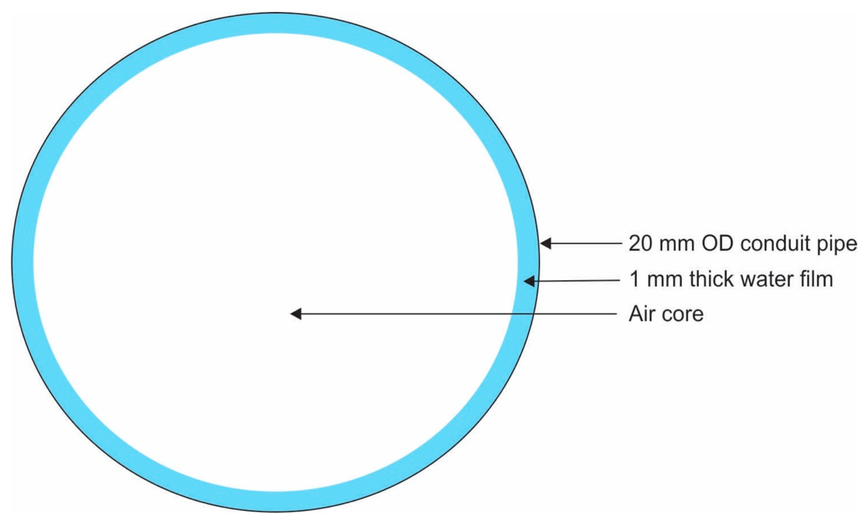
The anticipated falling-film thickness of 1 mm confirms continuous renewal of the liquid interface and stable gravitational flow. From the observed conditions: (i) gas-side mass transfer is leading, liquid-side resistance is insignificant, and (ii) interfacial balance is approached quickly. This confirms the idea that the evaporation rate is governed by the volume of air rather than interfacial kinetics. However, at large diameters, second-order effects may become significant (film instability and stream formation, maldistribution of liquid, and reduced interfacial area per unit volume), and these factors may limit scaling up and should be taken into consideration in a detailed design.
Engineering Interpretation and Design Implication
The results shown in
Table 7 confirm the following key engineering points:
Temperature sensitivity: evaporation performance is highly sensitive to temperature, with a small increase in air temperature resulting in a substantial reduction in the required reactor size.
Mass-transfer-controlled system: the process is primarily controlled by the moisture-carrying capacity of the air rather than heat transfer, which limits the effectiveness of dry-air operation.
Pipe-diameter optimization: increasing the pipe diameter considerably reduces the number of pipes required while maintaining a similar reactor footprint, thereby improving mechanical simplicity and reducing potential costs.
Airflow requirement: very large volumetric airflows are required, resulting in high fan-power demand, large ducting requirements, and increased operating costs.
Overall, the analysis shows that although dry-air evaporation is technically feasible, it is not economically attractive because of the high airflow requirements, low energy efficiency, large number of pipes, and associated mechanical and electrical demands. These limitations indicate that dry-air evaporation alone is unlikely to be practical for industrial-scale application and motivate the integration of solar thermal energy and industrial waste heat to increase the air temperature and improve the overall performance of the system.
3.3. Feasibility Analysis of the Comparative Evaluation of Evaporation with Dry Air Versus Waste Heat
Table 8 presents a comparative evaluation of two evaporation configurations, namely (i) evaporation using dry air only, and (ii) direct utilization of waste heat within the evaporation reactor.
3.3.1. Dry Air Process
The dry air configuration (
Table 8) is governed primarily by the psychrometric capacity of air. At an inlet temperature of 40 °C, the moisture carrying capacity of air is limited, resulting in a relatively low evaporation rate per pipe (0.0465 L/h). Consequently, many pipes (approximately 2150) and high air flow rates (approximately 13,700 m
3/h) are required. This leads to high fan and pump power requirements and, therefore, high operating costs.
The results confirm that evaporation in this configuration is mass transfer controlled, with negligible contribution from heat transfer through the pipe wall. As a result, pipe diameter has a limited effect on reactor size, while air temperature is the dominant design parameter.
3.3.2. Direct Waste Heat Process
The direct waste heat configuration (
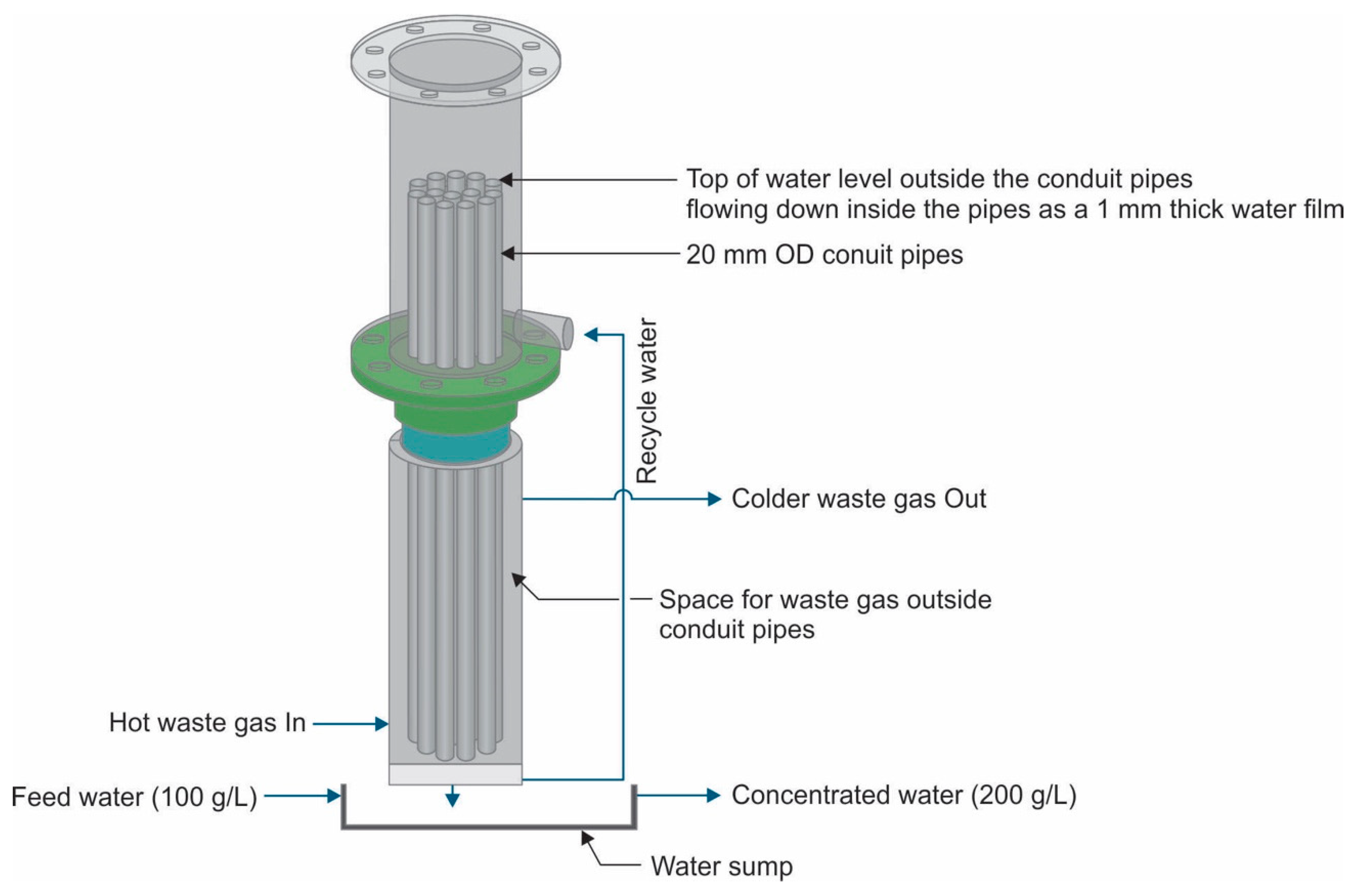
Table 8) is fundamentally different, as evaporation is governed by heat transfer through the pipe wall. The use of high-temperature waste gas (144 to 80 °C) allows evaporation at elevated temperatures (60 °C), significantly increasing the evaporation rate per pipe (0.157 L/h). This results in a much smaller number of pipes (approximately 635) and a compact reactor (approximately 0.42 m diameter).
An additional benefit is the recovery of approximately 156 kg/h of clean condensate through cooling of the water-saturated waste gas. This improves overall water recovery and enhances process sustainability.
3.3.3. Overall Comparison and Implications
The results in
Table 8 demonstrate that direct utilization of waste heat provides the most attractive design option from both technical and economic perspectives. Relative to the dry air configuration, the waste heat configuration reduces
Number of pipes by approximately 70%;
Reactor diameter by approximately 65%;
Airflow requirement by approximately 94%;
Electrical power demand by approximately 88%;
Capital cost by approximately 84%.
Although the waste-heat configuration is more dependent on heat-transfer performance and pipe-wall thermal resistance, the substantial reduction in airflow and equipment size outweighs these limitations. The dry-air configuration remains technically feasible and may be attractive in regions with abundant warm, dry air, but its large airflow requirement significantly increases both capital and operating costs.
Overall, the results confirm that direct utilization of industrial waste heat represents the preferred evaporation strategy for large-scale saline-water concentration and resource recovery applications.