Article

Chromium in Slag from SOEL Interconnects Remelting: Characterization and Recycling Potential

1
Institute of Mechanical Process Engineering and Mineral Processing, TU Bergakademie Freiberg, Agricolastraße 1, 09599 Freiberg, Germany
2
Structure and Function of Materials (IMD-1), Institute of Energy Materials and Devices (IMD), Forschungszentrum Jülich GmbH, Wilhelm-Johnen Straße, 52425 Jülich, Germany
3
Helmholtz-Zentrum Dresden-Rossendorf, Helmholtz Institute Freiberg for Resource Technology, Chemnitzerstraße 40, 09599 Freiberg, Germany
*
Author to whom correspondence should be addressed.
Minerals 2025, 15(9), 904; https://doi.org/10.3390/min15090904
Submission received: 25 July 2025 / Revised: 13 August 2025 / Accepted: 15 August 2025 / Published: 26 August 2025
(This article belongs to the Special Issue Characterization and Reuse of Slag)

Abstract

The recycling of interconnects from solid oxide electrolyzer (SOEL) stacks is essential for closing material loops in green hydrogen systems. Since it is mostly made of high-quality stainless steel, remelting is the most practical recovery route, but it inevitably generates slag, where strategic elements like chromium (Cr) are retained. This study investigates the mineralogical and grain characteristics of slag from SOEL interconnect remelting, with an emphasis on Cr distribution and its recovery potential. A correlative approach was applied using X-ray diffraction (XRD), scanning electron microscopy-based mineral liberation Analysis (MLA), and X-ray computed tomography (XCT). Cr was primarily found in magnesiochromite Mg(Al,Cr)2O4 (~54 wt.% Cr), constituting only ~5 wt.% of the slag, while lower concentrations were also detected in monticellite and åkermanite. XCT revealed the macroscopic heterogeneity of the slag system, with metallic inclusions and pores concentrated near the metal–slag interface, indicating density-driven settling. Cr-rich spinels were fine-grained (x50,2 ≈ 55 µm), irregular in shape, and partially intergrown, presenting challenges for mechanical liberation and physical recovery. These features, combined with their compositional selectivity, suggest that Cr-rich spinels are promising candidates for future Engineered Artificial Mineral (EnAM) strategies aimed at enhancing selective recovery from slag.

1. Introduction

Solid Oxide Cells (SOCs), including Solid Oxide Fuel Cells (SOFCs) and Solid Oxide Electrolyzers (SOELs), represent a crucial technology for energy conversion and hydrogen production due to their high efficiency and versatility. As global energy systems transition towards sustainability, SOELs are emerging as key components in large-scale green hydrogen production [1,2,3]. One of the crucial components in a SOEL stack is metallic interconnects, which require excellent electrical conductivity, high oxidation resistance, low cost, and good and high mechanical strength in operating conditions [2,3,4,5]. These interconnects are essential to the structural and functional integrity of SOEL stacks, accounting for 60–80 wt.% of the total stack [6]. Typical metallic interconnects used in SOC system are Cr-based alloys, ferritic stainless steel, austenitic stainless steel, Fe-Ni-Cr based alloys, and Ni-Fe-Cr-based alloys [7].
In a typical SOEL stack, the interconnects are assembled as layered structures composing of steel substrate with protective spinel coatings, glass sealant, and current collectors such as nickel meshes [2,8,9]. These assemblies serve to electrically connect individual electrochemical cells in the stack while providing gas tightness and mechanical support under high-temperature conditions. However, these interconnect assemblies degrade over time and require recycling at the end of their lifetime [8,9]. Current proposed recycling approaches of SOEL interconnect assemblies involve pyrometallurgical remelting [2,9,10] since interconnects are mostly made of stainless steels. Lastam et al. [9,10] extensively studied the feasibility of recovering metallic resources, especially the high-quality stainless steel, from end-of-life interconnect assembly remelting under various conditions at a lab scale. In the remelting process, metal alloy and flux are added together and melted at high temperatures. As a result, metal melt and the by-product called slag are produced. In metallurgy, slag plays an essential role in protecting the molten metal from oxidation and capturing impurities, and facilitating the partitioning of metallic elements [11].
Due to thermodynamic equilibrium and transport processes, resulting slags contain chromium, which is a critical component of stainless steels; therefore, strategies for chromium must be explored. Slags from ferrochromium and stainless-steel industries commonly contains chromium in ranges of 2–10 wt.% and 1–2 wt.%, depending on the process design and feed [12,13]. Under typical steelmaking conditions, chromium exists predominantly as Cr(III), which is relatively immobile [14], but could be oxidized to hexavalent chromium (Cr(VI)) under oxygen-rich environments. High Cr content in slags poses a significant challenge for complete slag valorization due to concerns over Cr (VI) formation, which is carcinogenic [15] and environmentally hazardous [16]. According to the European Council Decision [17], leaching limit value of total chromium (Cr) must not exceed 0.5 mg/kg (at a liquid-to-solid ratio of 10 L/kg) for a slag to be classified as inert waste and suitable for landfill. In Germany, the total chromium content must be lower than 600 mg/kg for the use of steel slags in concrete [18]. Thus, minimizing Cr leaching and maximizing its recovery are essential for environmental protection and also for the holistic circular economy of strategic metals.
The challenge of the Cr recovery and leachability is closely related to its distribution in the mineral phases of slag [13,19,20]. Cr is generally very diluted and spread over different mineral phases in the slag. Previous research on ferrochromium and stainless-steel slags [9,12,21,22,23,24,25,26,27,28,29] have demonstrated that Cr is mostly distributed in various spinel phases and several silicate phases, sometimes as chromium oxide and metallic particles as well. From the recovery and leachability perspective, the incorporation of Cr into the spinel crystal structure is preferred. The spinel phase can be identified as the leaching control mechanisms since it is chemically stable and has low leachability [20,30,31]. However, the presence of Cr within the phases is mostly qualitative and is not quantified systematically.
Similar Cr distribution behavior is expected in slags derived from remelting SOEL interconnects. A scrap-based steelmaking route was experimentally investigated as an interconnect recycling strategy [10]. This pathway generates slags under controlled pyrometallurgical conditions with low oxygen partial pressures, pre-designed flux chemistry, and controlled cooling conditions. By deliberately optimizing these conditions, it is possible to enrich Cr into a single phase within the slag and stabilize Cr with good processing properties for an efficient recovery. This concept was introduced as ‘Engineered Artificial Minerals—EnAM’ and applied to different slag systems where the target metal was concentrated in a specific mineral phase by changing slag composition and cooling conditions [32,33,34]. In addition, the EnAM approach helps to enhance mechanical and chemical recovery by forming a Cr-containing phase that is suitable for selective extraction.
For these reasons, this study focuses on understanding the occurrence, distribution, and morphology of Cr-containing phases in slags derived specifically from the recycling of SOEL interconnects, representing an exemplary material of highly alloyed stainless steels. Using several advanced analytical methods such as XCT, XRD, and SEM-based MLA analyses, we characterize the bulk and microstructural properties of the slag, considering each method in a correlative and complementary way. The findings provide insights into how Cr behaves during remelting, and how this behavior can be taken into account to design more effective metallurgical and mechanical recovery processes and support the sustainable valorization of SOEL interconnect slags as well as other industrial slags.

2. Materials and Methods

2.1. Slag Production

The slag was generated by remelting an interconnect with spot-welded nickel meshes. The interconnect consisted of a Crofer 22 APU steel substrate coated on the airside with MnCo1.9Fe0.1O4 (MCF) and LaMn0.45Co0.35Cu0.2O3 (LCC10) oxide layers. The thicknesses of MCF layer and LCC10 layer were around 100 µm and 130 µm accordingly. This component was part of the repeating layers of an EoL Jülich F10 SOC stack (F1004-94). The stack had an operating lifetime of 2700 h at 800 °C in the co-electrolysis mode. Prior to remelting, the component was cut to fit inside a crucible made of yttrium-stabilized zirconia (YSZ), and a basic flux was added at 20 wt.% relative to the total feed. The flux was composed of dolomite and silica that were mixed to reach a slag basicity of 1.5. Commercially available dolomite (Rheinkalk, Wülfrath, Germany, 57CaO-34MgO-4Al2O3-3SiO2 in wt.%) and silica powders (Sibelco, Dessel, Belgium, 99 wt.% SiO2) were utilized. To ensure homogeneity, the flux was premelted at 1550 °C under argon. Table 1 shows the composition of the pre-molten flux, its liquidus temperature (Tliq), and its basicity (B). Slag basicity was calculated as
B = CaO + MgO SiO 2
following the approach of Xiao and Holappa [35], where a target basicity of 1.5 was reported to promote optimum spinel formation. Al2O3 was excluded from the calculation because it was considered an amphoteric component and its omission ensured consistency with reference basicity values. Tliq was determined using FactSage 8.3 with FactPS and FToxid thermodynamic databases [36].
The crucible was placed inside a high-temperature furnace, heated to 1550 °C at 10 °C/min under argon, and held at the peak temperature for 2 h. It was then furnace-cooled to achieve near-equilibrium cooling conditions. Once the target holding time was reached, the furnace was switched off, and the material was left off in the closed furnace to naturally cool to room temperature. This produced a relatively slow cooling rate, favoring the crystallization of primary phases within the slag. The weight of the feed and product materials, as well as the calculated metal yield, are summarized in Table 2. The unrecovered material weighing around 69 g was likely slag lost due to fusion with the crucible.
The product metal was composed of 73 wt.% Fe, 18.5 wt.% Cr, 7.7 wt.% Ni, 0.47 wt.% Co, and 0.24 wt.% Mn. For more details on Jülich SOC stack interconnects, product metals, and their potential recycling strategies, the reader is referred to the studies of Lastam et al. [9,10].
After complete solidification, the metal melt and bulk slag were removed from the crucible. The crucible and bulk slag were scanned using EinScan Pro 2X Plus 3D scanner (Shining 3D Technology GmbH, Stuttgart, Germany) to visualize the formation of the slag and metal melt inside the crucible. Figure 1a illustrates the metal melt and slag formation resulting from the remelting experiment. The ‘as-received’ slag sample, shown in Figure 1b, is an intact slag body (56.10 g) with dimensions of 6 cm × 5 cm × 2.5 cm. It originates from the center of the crucible. The rest of the slag attached to the crucible was not considered in this study as it interacted with the crucible and stayed on the crucible wall.

2.2. Characterization Methods

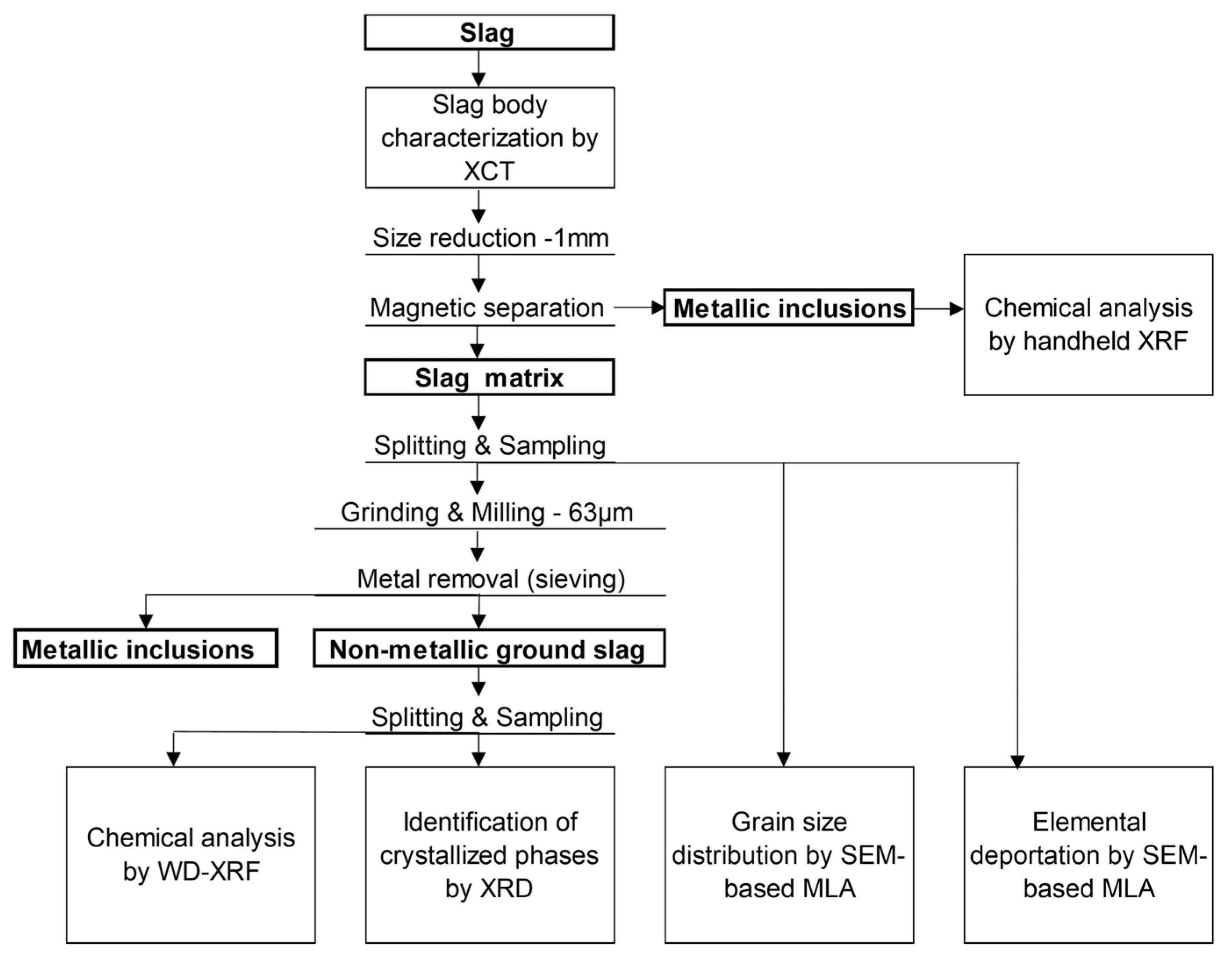
Slag sample was characterized using several analytical approaches to assess its chemical composition, mineralogy, phase distribution, and elemental deportation. The overall methodology is depicted in Figure 2.
X-ray computed tomography (XCT) was used as a non-destructive 3D technique to analyze the internal structure, metallic inclusions, and porosity of the slag before crushing and bulk analyses. XCT was used to better understand the internal slag structure throughout the entire sample due to crucible–slag interactions, slag–metal interactions, and thermal processes in general. After that, the bulk slag was comminuted to 1 mm using cutting mill (pulverisette 15, Fritsch, Idar-Oberstein, Germany), followed by magnetic separation using a permanent magnet to remove the most metallic inclusions from the non-metallic slag matrix. The remaining slag matrix was split by a rotary micro riffler; the 10 g sub-sample was prepared for MLA. The rest material was then further milled and ground using a centrifugal ball mill (pulverisette 6, Fritsch, Idar-Oberstein, Germany) to <63 µm, and the remaining metallic inclusions were sieved from it. The ground slag samples were homogenized, split again by the rotary micro riffler (Quantachrome Instruments, Odelzhausen, Germany), and prepared for chemical and mineralogical analysis. The sub-samples were prepared based on the requirements of analytical methods employed.
Wavelength-dispersive X-ray fluorescence (WD-XRF) was used to determine the oxide composition of the slag. X-ray diffraction (XRD) identified the crystalline phases present in the slag. Furthermore, using a Mineral Liberation Analyzer (MLA), we conducted assessments of the microstructure and morphology of the slag, identifying elemental associations; investigated the spatial association of elements, critical for understanding potential recovery processes; and provided quantitative data on the size range of Cr-bearing phases. The MLA comprises field emission SEM (FE-SEM) equipped with two energy-dispersive X-ray (EDX) detectors.

2.2.1. X-Ray Computer Tomography

The slag body was positioned at a tilted orientation in a plastic sample cylinder (inner ⌀ 5 cm) due to its high aspect ratio. This tilted positioning corresponds to a laminographic geometry, which is often employed in XCT for flat or elongated samples [37]. Laminography helps to reduce limited-angle reconstruction artifacts and enhances image quality along the longitudinal axis. The prepared sample was scanned using Zeiss Xradia 510 Versa XCT (Carl Zeiss AG, Oberkochen, Germany). The scans were performed with the parameters listed in Table 3 to analyze the whole slag sample (Figure 1b) in a large field of view (FOV, 50.1 µm voxel size).
Different components can be distinguished according to the differences in their grayscale in the image by the scan. Materials with distinguished densities for instance, metallic inclusion, slag phase, and pores in the slag body can appear bright white, light gray and dark gray/black, respectively. The grayscale intensity in XCT images corresponds to the local X-ray attenuation coefficient, which depends on the average atomic number of the material to the power of four, the X-ray energy, the material density, and the local thickness along the beam path [38]. Therefore, it is advantageous for distinguishing metallic inclusion and slag phase in the sample by images obtained from the scans. The projection images were reconstructed using the software Scout & Scan Reconstructor (Version 11.1.8043, Carl Zeiss AG, Oberkochen, Germany).
The reconstructed images were exported to tag image file format (.tiff) images as an image stack and followed by pre-processing steps using the software Fiji (ImageJ 1.54f). All images were smoothened by non-local means denoising (sigma = 15, smoothing factor = 1), preserving the grain boundaries, and sharpened by Unsharp mask (sigma = 1 px, mask weight = 0.3); we applied Despeckle to remove speckles after sharpening.
Indeed, 50 slices were used for segmentation using pixel classification workflow on ilastik (version 1.4.0). The software ilastik uses machine learning algorithms for identifying pixels of an image that belong to a class of interest with interactive training [39]. To configure this workflow, the user defined four classes such as ‘metallic inclusion’, ‘slag matrix’, ‘pores’, and ‘background’ and trained the algorithm. The validity of the training was evaluated by processing untrained 50 slices.
Four phases were classified and binarized to calculate the porosity of the slag body and size distribution of metallic inclusion and pores. The analysis of the final image stack and its visualization were performed using the software Fiji and VGStudio MAX 3.3 (Volume Graphics GmbH, Heidelberg, Germany).

2.2.2. Chemical Composition by WD-XRF

WD-XRF (Malvern Panalytical, Kassel, Germany) was used to determine the bulk chemistry of the slag sample. The ground sample (<63 µm) was calcined at 950 °C for 1 h. Calcined samples were mixed with lithiumtetraborate in the ratio of 1:8 to produce fused beads using TheOx advanced fusion furnace (Claisse, Malvern Panalytical, Kassel, Germany). The analysis was carried out using a PANalytical Axios spectrometer, equipped with a Rh tube. Depending on the element, the voltage and current were adjusted, varying between 25 and 60 kV and between 66 and 160 mA. The data were obtained from the fully calibrated WROXI program, provided by the manufacturer. All elements were in the calibration ranges.

2.2.3. Mineralogical Analysis by XRD

The bulk mineralogy of the slag was determined by means of XRD analysis. For the preparation of the samples, they were wet-milled down to 4 µm by a McCrone mill (Retsch, Haan, Germany) with zirconium oxide milling balls. After drying the samples, they were deagglomerated and further prepared in a sample holder by the so-called back-fill method. The back-filling method is used to minimize preferred orientation effects in such types of samples. Measurements were performed in a PANalytical Empyrean diffractometer (Malvern Panalytical, Kassel, Germany) equipped with a Co-tube and a PIXcel 3D medipix 1 × 1 area detector. The tube operated at 35 kV and 35 mA, with an iron filter placed on the primary beam side to reduce K-beta radiation. The irradiated area on the sample was maintained at a constant of 12 × 15 mm2 using an automated divergence slit. The 2-theta range for measurements was set from 5° to 80°, with a step size of 0.0131° 2-theta. The total measurement time per sample was approximately 2 h and 30 min. Phase identification was carried out using the ICDD PDF-4 + database, while quantification was performed using the Rietveld method through the Profex/BGMN (v. 4.1) software package.

2.2.4. Elemental Distribution and Mineral Composition by SEM-Based MLA

For quantitative mineralogical analysis using SEM-based MLA, the crushed sample, with a particle size of <1 mm after the removal of metal inclusions, was used to keep the internal morphology of the mineral phases intact and to investigate the interplay and the properties of the individual phases. A grain mount with a diameter of 30 mm was prepared. The process involved mixing the sample material with graphite powder and epoxy resin to create an epoxy block. The epoxy block was then polished coated with carbon on the sample surface. The MLA consists of an FEI Quanta 650F (Thermo Fisher Scientific, Walthan, MA, USA) FE-SEM equipped with two Bruker Quantax X-Flash 5030 (Bruker, Billerica, MA, USA) EDX detectors. The identification of mineral grains by MLA involves back-scattered electron (BSE) image segmentation and the collection of EDX spectra of the particles and grains distinguished in grain-based X-ray mapping (GXMAP) mode.

2.2.5. Thermodynamic Equilibrium Calculations

The slag chemical composition, as determined in Section 2.2.2, was inputted into the Equilib module of FactSage 8.3 to predict the equilibrium phases at the furnace temperature (1600 °C) and their subsequent evolution upon cooling to 100 °C. Elements with lower than 0.5 wt.% are excluded for the equilibrium calculation. Furthermore, the temperature-dependent chromium partitioning among the equilibrium phases was also evaluated. Commercially available thermodynamic databases (FToxid, SGPS) were employed in the thermodynamic calculations, with the oxygen partial pressure fixed at 10−10 bar to simulate inert furnace conditions.

3. Results & Discussion

3.1. Slag Body Characterization by XCT

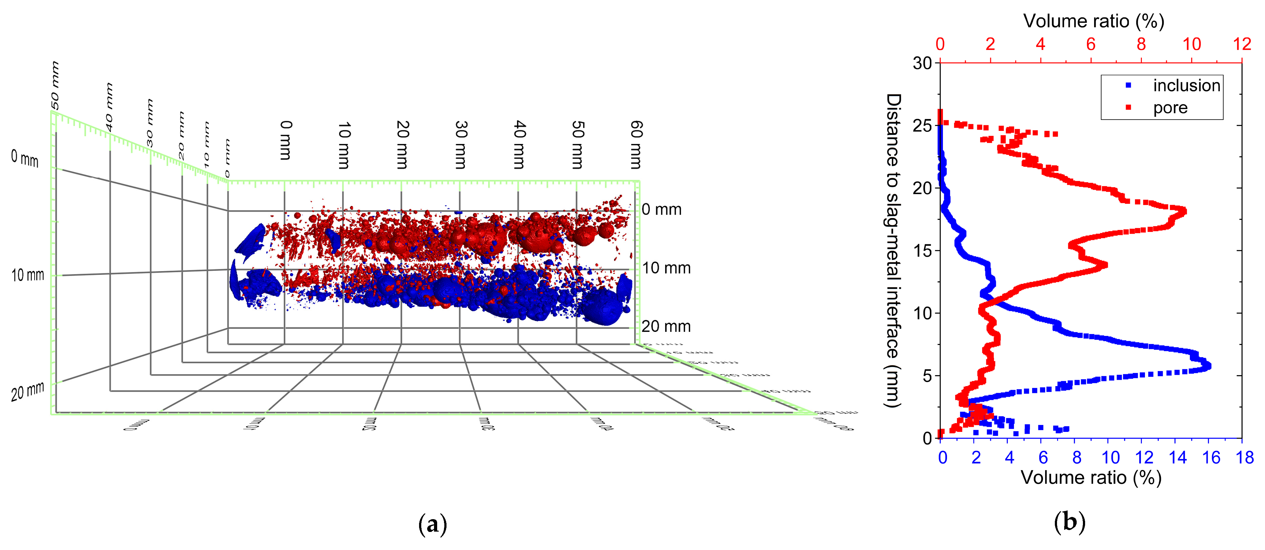
The results of the overview scans of XCT analysis are shown in Figure 3 in the form of 2D cross sections taken from the center of the tiff stack at different locations in the slag sample. Three distinct phases were distinguished based on grayscale contrast: the slag matrix appears in medium gray, pores in dark gray to black, and metallic inclusions in bright white. These differences arise from the variations in X-ray attenuation between the phases. The cross sections revealed that the slag body contained numerous metallic inclusions and pores of varying size and distribution. To better understand the spatial distribution of metallic inclusions and pores in the slag, the 3D structure of the slag body was constructed and visualized by VGStudio MAX 3.0 software. The rendered metallic inclusions and pores are shown in Figure 4a. It can be observed that the metallic inclusions were mainly concentrated at the bottom of the slag body (metal alloy–slag interface), whereas the inclusion content on the top of the slag (slag–atmosphere interface) was relatively small.
The volume ratio expressed as a function of sample thickness was obtained in each slice, as depicted in Figure 4b. The volume ratio was calculated as the ratio between inclusion volume and slag volume in a single slice. As shown in the graph (Figure 4b), there is an enrichment of metallic inclusions at a height of 6 mm from the metal alloy. In contrast, pores were primarily concentrated in the upper region of the slag at around 18 mm from slag–metal interface, with an increasing volume ratio seen toward the slag–atmosphere interface. This phenomenon can be explained by the slow solidification of the slag. Slow cooling allowed the denser phase to settle down while the lighter phase rose up to the top. The inclusion and porosity analysis showed that metallic inclusions and pores in the slag accounted for 4.34 vol. % and 4.46 vol. % of the sample volume, respectively. It should be noted that the inclusions and pores smaller than 50 µm are not illustrated here due to the resolution being limited by voxel size.
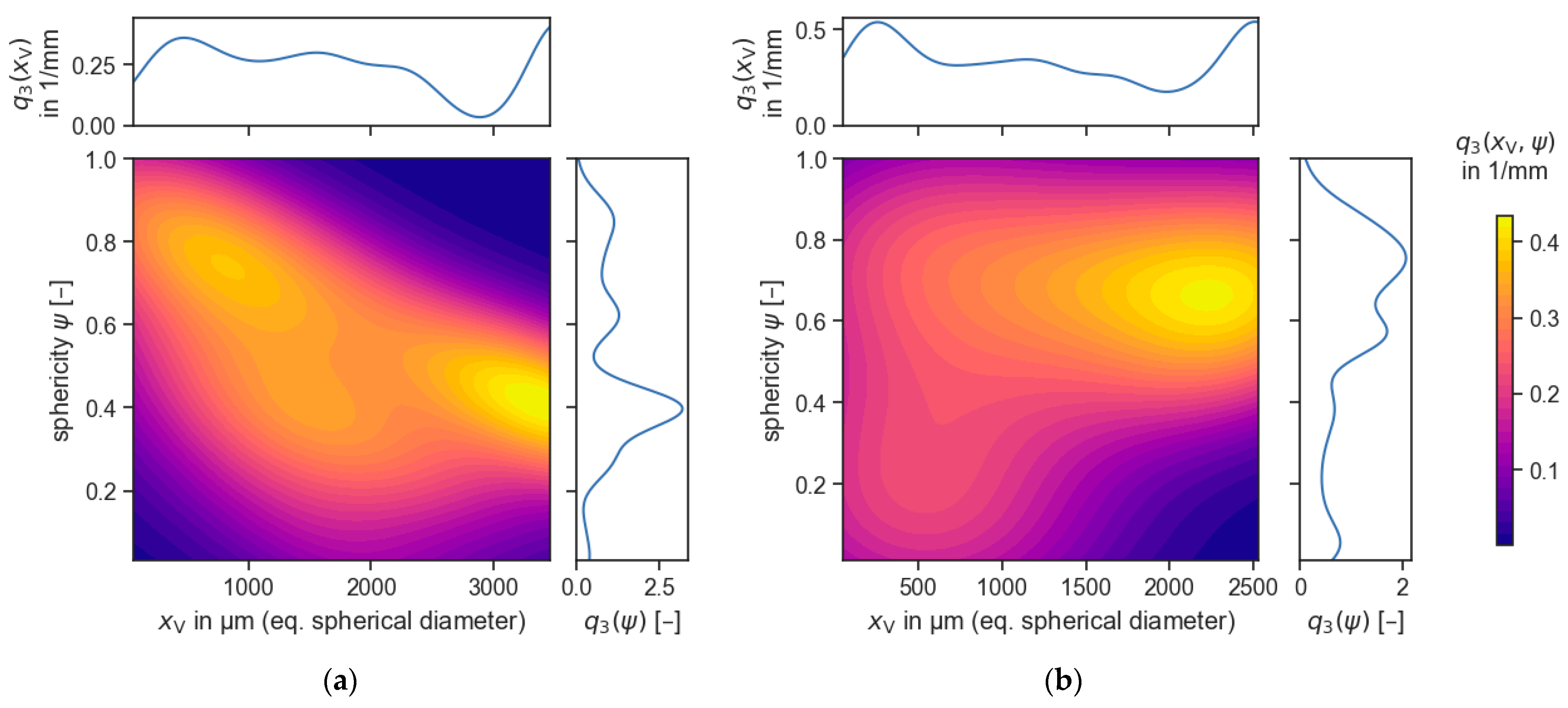
The data from the 3D XCT analysis are illustrated by a volume-based kernel density estimation (KDE) plot using a python script [40] and shown as two-dimensional particle property distributions in Figure 5. It is a good visualization of occurrence of the two particle properties such as particle size and shape descriptor; in this case, we are dealing with sphericity [40]. The plot also includes the marginal distributions (along top, right axes) providing 1D projections of the data, i.e., particle size distribution and particle shape distribution. Figure 5a shows the metallic inclusion particles, showing bimodal distribution. The first dense area, around 1000 µm in diameter and displaying sphericity values near 0.75, corresponds to small, well-rounded droplets that likely solidify individually with minimal interaction. In contrast, a second peak is observed around 3400 µm with sphericity near 0.45, indicating the presence of larger, less spherical droplets. This second dense area is interpreted as a result of coalescence—driven by gravitational settling and increased droplet mobility in the melt—particularly near the metal–slag interface. The lower sphericity of these larger inclusions reflects incomplete re-shaping before solidification. This bimodal distribution highlights the complex dynamics of droplet formation and merging, governed by density difference, interfacial tension, and local flow fields during cooling. This interpretation is supported by previous studies [41,42,43].
In contrast, the KDE plot for pores (Figure 5b) reveals that the majority of pores range between 500 and 2500 µm in diameter, with the highest density occurring around 2500 µm. The sphericity value lies at 0.62, with a notable concentration. However, a fraction of pores with low sphericity (<0.4) may indicate irregular or interconnected pore structures, likely formed due to trapped gas bubbles or the incomplete fusion of material during cooling. Unlike metallic droplets, pores exhibit limited mobility due to the low density difference with the melt, reducing their likelihood of coalescence and resulting in a more heterogeneous distribution.
The comparison between inclusions and pores highlights that metallic inclusions tend to be more spherical and uniformly distributed, whereas pores exhibit greater morphological variability. This distinction is important for understanding the phase separation behavior during slag solidification and optimizing recovery strategies for metallic phases. Furthermore, pore size and its distribution influence the density and breakage behavior of slag particles, which can in turn affect comminution efficiency and the liberation characteristics of the slag.

3.2. Chemical Composition

The bulk chemical composition of the slag was analyzed by WD-XRF. Table 4 summarizes the results of the overall chemical analysis. The main components of the slag are dominated by SiO2 (29.1 wt.%) and CaO (26.2 wt.%), followed by significant amounts of MgO (16.7 wt.%) and Al2O3 (5.2 wt.%). These oxides mostly come from the flux added which is common in metallurgical slags. The relatively high CaO content suggests a moderately basic slag, which could influence its physicochemical properties such as melting behavior, slag viscosity, and stability.
Cr2O3 is present at 6.9 wt.%, indicating that significant amounts of the Cr from the remelted interconnect material remained in the slag. Fe was present as Fe2O3 (1.7 wt.%), suggesting that Fe was partially retained in the slag phase, potentially as residual oxide inclusions. Additionally, a minor amount of Ni was found, likely originating from the Ni-mesh of the interconnect assembly.
The presence of ZrO2 (6.2 wt.%) is notable, as it likely originates from crucible interaction with the slag during the remelting process. Under the high-temperature conditions, slag composition used, and prolonged holding time, the partial dissolution of the crucible into slag is possible. Previous studies have reported similar observations—for instance, grain structure degradation and the dissolution of ZrO2 in the slag environment [44,45]. Such contamination is a well-known issue in high-temperature processes [46], particularly in lab-scale trials, due to high surface area-to-volume ratio of the crucible-to-ingot system. In contrast, industrial-scale steelmaking processes use basic refractory bricks (MgO- or Al2O3-based), which are less prone to slag corrosion [47]. Thus, it is expected to show significantly reduced levels of crucible-derived contamination. Nevertheless, this finding shows that crucible contamination should be considered when assessing slag quality.
This suggests potential contamination, which could influence slag crystallization behavior and phase formation. Other minor elements, such as BaO (1.6 wt.%), TiO2 (0.3 wt.%), CuO (0.06 wt.%), and SrO (0.03 wt.%), indicate trace impurities that may have originated from alloying elements in the interconnects or flux additions.

3.3. Mineralogy

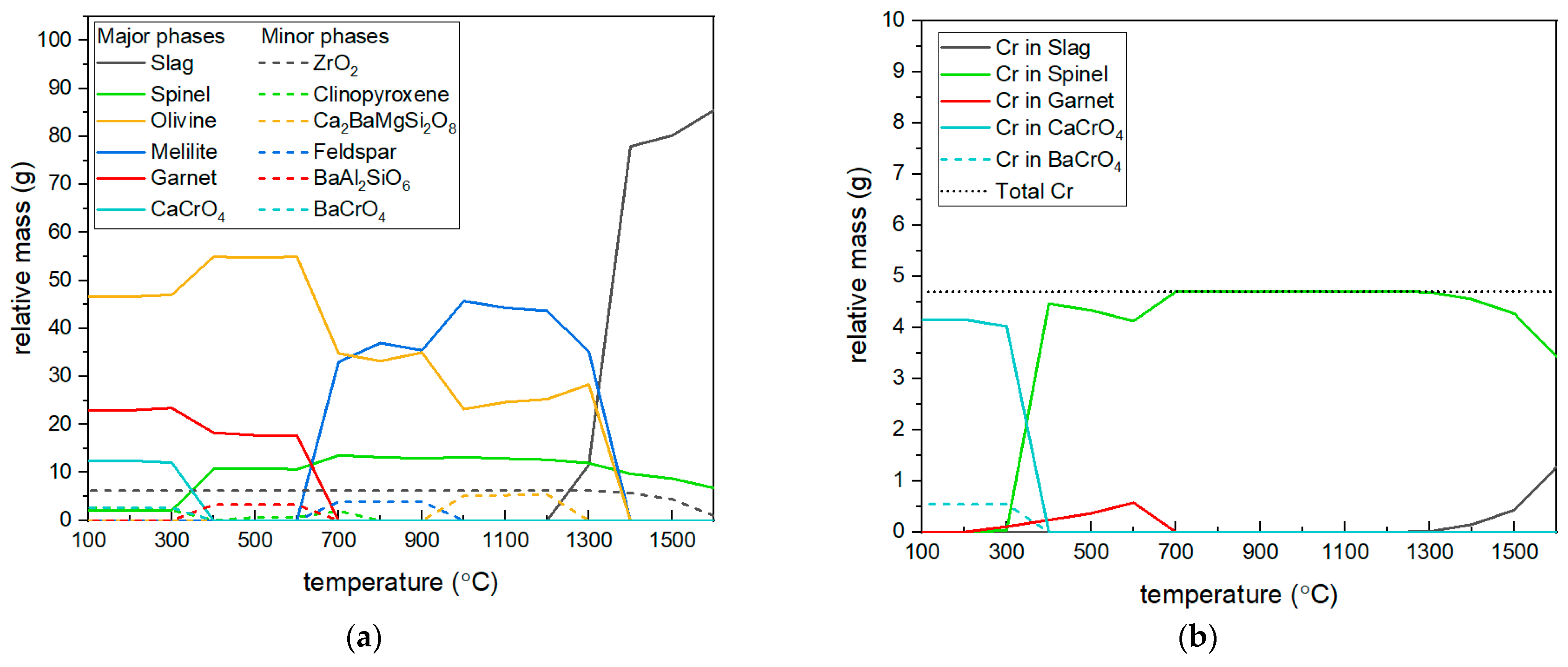
The equilibrium solid and solid solution phases were determined as a function of temperature using Factsage 8.3, based on the slag chemical composition presented in Table 4. For simplicity, only slag components with concentrations greater than 1 wt.% were considered in the calculations. The relative amounts of resulting phases are shown in Figure 6a. The major phases across the temperature range are slag, spinel, olivine, melilite, garnet, and CaCrO4. Furthermore, several minor phases with relative amounts <10 g are also present, including ZrO2, clinopyroxene, Ca2BaMgSi2O8, feldspar, BaAl2SiO6 and BaCrO4.
The distribution of Cr among the equilibrium phases was also evaluated. According to calculations, the maximum Cr amount in the system is approximately 4.7 g. At 1600 °C, Cr is initially dissolved in the slag phase but begins to be partitioned into the spinel phase upon cooling to 1400 °C. Cr predominantly remains in the spinel phase over a broad temperature range (1400 —700 °C). Below 700 °C, a part of Cr partitions into the garnet phase until 400 °C. At lower temperatures, the spinel phase becomes less stable, and Cr redistributes into newly forming stoichiometric solid phases, specifically CaCrO4 and BaCrO4. Overall, the results confirm the role of the spinel phase as the primary Cr-hosting phase under the given slag composition and inert equilibrium conditions.
The slag was then characterized using XRD- and SEM-based MLA for its mineralogy, which goes beyond the simple chemical analysis performed with XRF. Given the complex mineralogical nature of the slag, both techniques were applied in a complementary manner to improve phase identification and better quantification. The phase contents determined by XRD (See Table A1) and MLA are shown in Figure 7. The comparison shows good qualitative agreement between the methods in terms of identifying the major phases in general. However, quantitative differences also showed significance due to the methodological differences between bulk diffraction and spatially resolved imaging.
XRD results revealed that the dominant crystalline phase in the slag is monticellite, which is a silicate mineral of the olivine group and accounts for the majority of the detected phases. Other identified phases include magnesiochromite, åkermanite (melilite mineral), zirconia (ZrO2), and quartz (SiO2). While XRD is well suited for identifying major crystalline phases, it has inherent limitations in detecting fine-grained or solid solution phases and in resolving overlapping or broadened diffraction peaks [21,48]. Magnesiochromite was identified as the primary Cr-bearing phase (12.5 wt.%), but its precise composition and possible cation substitutions, such as Al, Fe, and Mn, could not be resolved due to peak overlap and crystallographic similarity within the spinel group. The presence of Fe-oxide phases was also not detected in the XRD data, likely due to their low abundance and sub-micrometer grain size. The abovementioned limitations were resolved using SEM-based MLA for slag mineralogy. It enabled spatially resolved phase mapping and revealed more compositionally diverse spinel groups with different compositions. These are also listed in Figure 7. It also includes the solid solution series of high Cr-containing spinel (Spinel I ss). This indicates a broader range of Cr incorporation than suggested by XRD.
Overall, the comparison between equilibrium modeling and experimental results shows strong correspondence in identifying major phases and Cr partitioning behavior. Theoretical predictions provided a reliable framework for interpreting phase stability, while experimental techniques confirmed the dominant role of spinel as a Cr host and revealed additional complexities not predicted by equilibrium models.

3.4. Cr Distribution & Cr-Bearing Phase Morphology

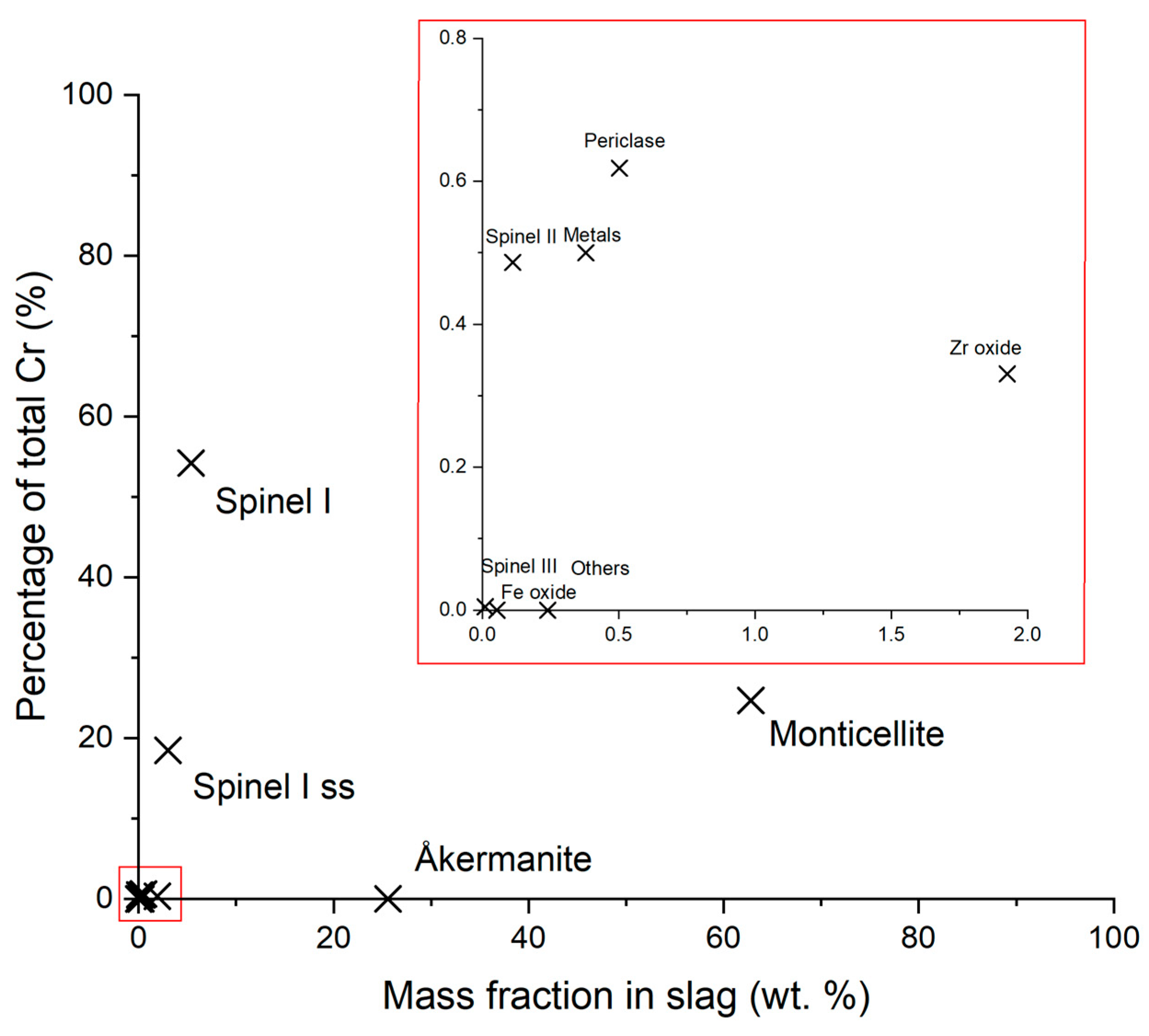
To understand the partitioning of Cr in the slag, the phase composition was analyzed, focusing on Cr concentration and the mass fraction of each phase in the slag. Figure 8 illustrates the Cr distribution in each phase and mass fractions of each phase in the slag. The result shows that Cr is primarily concentrated in spinel phases, particularly Spinel I (Mg0.85Al0.15)(Cr1.78Al0.12)O4 (54.2 wt.% Cr), despite its relatively low abundance (5.4 wt.% of the slag). This highlights a distinctive enrichment of Cr relative to the bulk slag and significantly exceeds Cr contents typically found in natural chromite ores. Spinel II (Mg0.91Ca0.01)(Al1.45Cr0.62)O4 and Spinel III (Mg0.91Mn0.04)(Al1.98Cr0.05)O4 contain only minor amounts of Cr (0.5–0.6 wt.%), making them less significant for extraction.
In contrast, silicate phases, including monticellite (24.7 wt.% Cr, 62.8 wt.% of the slag) and åkermanite (~18.5 wt.% Cr, 3.0 wt.%), constitute most of the slag but are less suitable for Cr recovery due to their incorporation into the slag matrix. Nevertheless, the considerable quantity of Cr remaining in the silicate matrix implies the necessity of the further optimization of pyrometallurgical conditions.
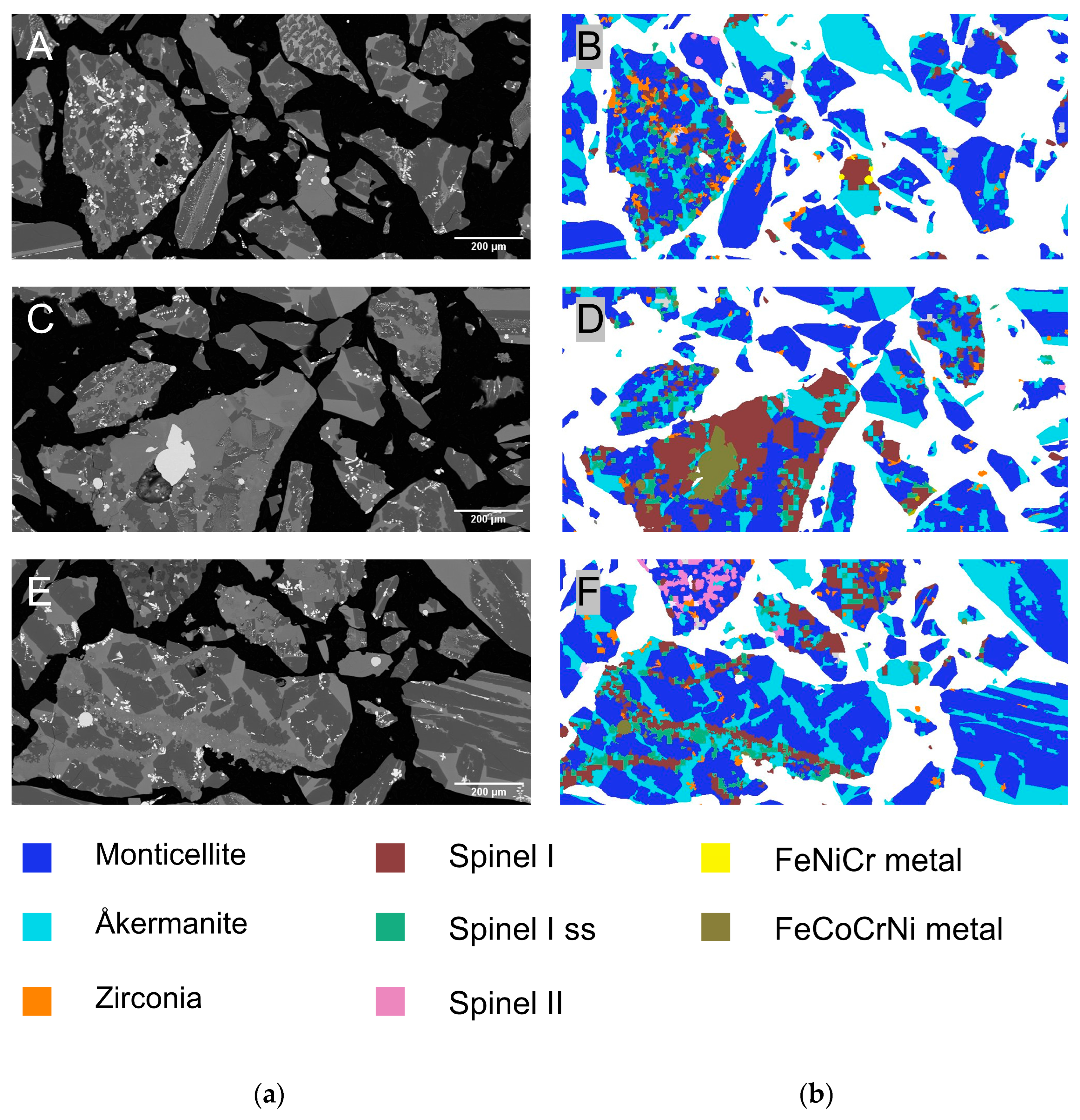
Figure 9 illustrates the morphological characteristics, the phase distribution of the slag particles, and their intergrowth. In the BSE images originating from the MLA measurements (Figure 9a), distinct contrast variations highlight differences in composition and density among the mineral phases. It could be seen that the microstructure of the slag matrix was rather heterogeneous. Inclusions in these silicate phases are too fine (smaller than the EDX measurement resolution), thus leading to differences in phase composition. This limitation of MLA especially in slag materials was addressed in the study of Schulz et al. [49]. The corresponding false-color MLA images (Figure 9b) provide phase-specific mapping of the identified minerals. Spinel I phase color-coded in brown. Its grain morphology was found predominantly irregular and angular. It suggests that spinel crystals may have precipitated first, forming distinct grains that are now embedded in the surrounding silicate matrix. Notably, in some regions (See Figure 9b(F)), spinels follow a linear pattern, which may indicate preferential precipitation along grain boundaries of earlier-formed silicate phases. Such a pattern suggests that spinel nucleation was influenced by the evolving microstructure of the slag melt during solidification.
Spinel I phase was also bound with metals and solid solutions with more impurities. This suggests the following two points: (i) metals from the alloy melt became depleted with Cr and (ii) conditions during slag cooling resulted heterogeneous crystal growth. The overview of the different metallic inclusions found in the slag particles after the metal removal is summarized in Table A2 under Appendix A. Although the composition of individual inclusions varied significantly, they predominantly consisted of Fe and Cr and some alloying elements such as Ni, Co, and Mn. In addition to their association with metallic inclusions, spinel phases were frequently embedded within the silicate matrices such as monticellite and åkermanite due to their early formation. The silicates were likely to be crystallized later.
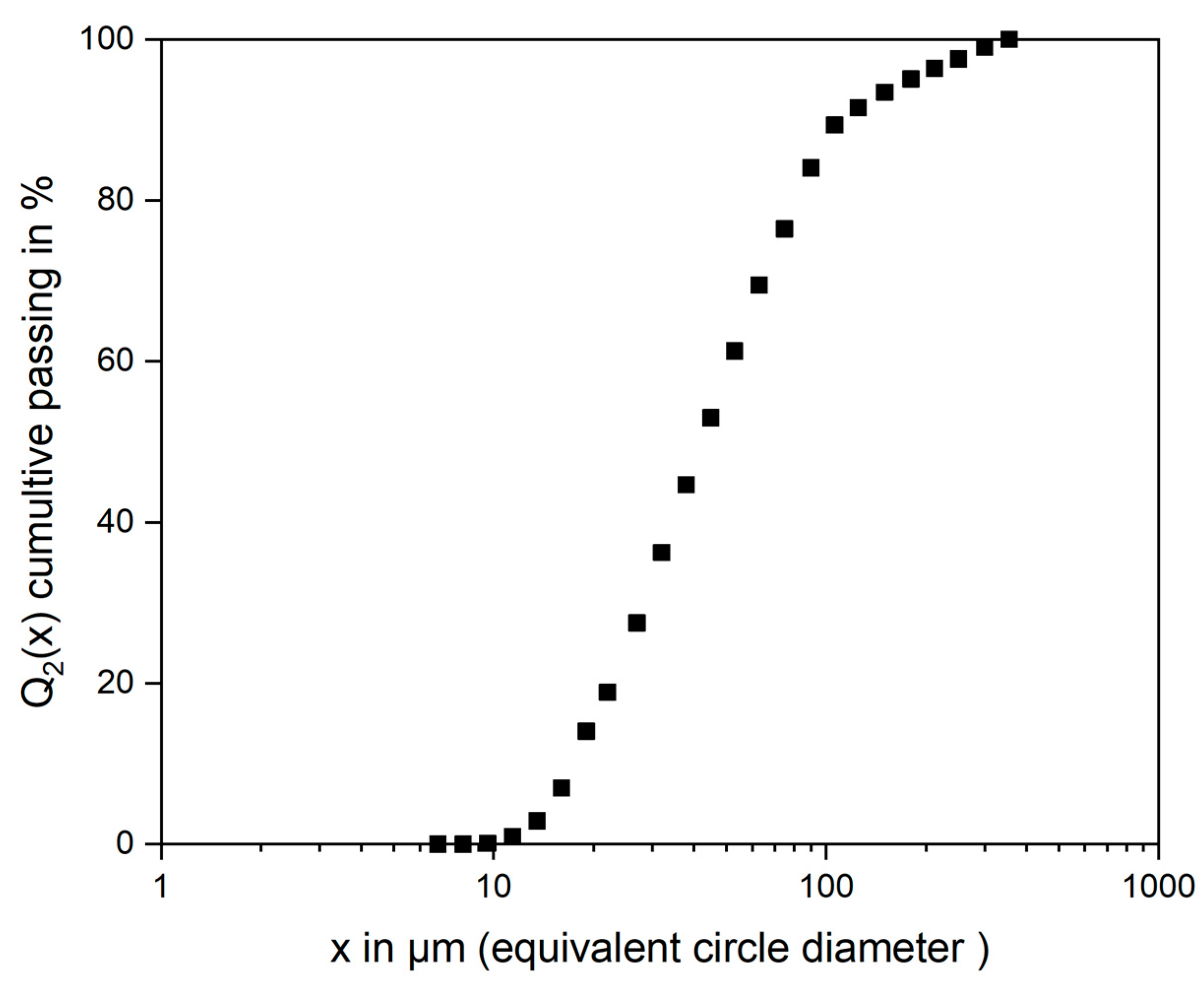
Another aspect of interest concerning a potential recycling process for this is the grain size of the Spinel I. Here, Spinel I and Spinel I ss were reclassified as one phase (now high-Cr-containing spinel) since they were intergrown and had relatively similar compositions. The area-based spinel size distribution is illustrated in Figure 10. The size distribution indicated that 50% of spinel particles (x50) had a size below approximately 55 µm, while 80% (x80) were below 106 µm. The distribution shows a gradual increase in cumulative passing below 50 µm, with the finer fraction (<10 µm) comprising only a small portion. Larger spinel particles (>200 µm) were relatively less frequent and were highly likely to be localized growth of several single-spinel grains, possibly due to variations in temperature gradients or phase interactions during solidification. These locally grown crystals, also known as clusters in different EnAM slag systems, can be visualized in 3D by using XCT [32,50,51].
The microstructural characterization confirmed that Cr-rich spinels are the dominant host phase for Cr in the remelted slag. The results also showed that these Cr-rich spinels have high Cr content, comparable to those found in naturally occurring chromite ores [52]. This selective concentration of Cr into a spinel phase provides a strong basis for applying the EnAM concept [53]. In this context, Cr-spinel functions as an intentionally engineered mineral phase to enrich critical elements, in this case Cr, during pyrometallurgical processing. This artificial mineral phase could then be a target for mineral processing. Conventional Cr recovery methods such as reduction roasting, alkali roasting, and leaching are typically energy- and reagent-intensive. The possible Cr recovery processes from this type of spinel are mostly mechanical separation due to high resistance to wet chemical methods [21]. However, the grade and recovery by mechanical separation are dependent on the degree of liberation [54,55]. Given that the degree of mineral liberation is size-dependent, larger initial crystal sizes enable liberation at coarser crushing and milling stages. The resulting slag contained spinel grains five to ten times larger than those in industrial EAF slags due to uncontrolled cooling conditions [22,50,51], but the spinel size distribution was in a fine range for potential mechanical separation. For effective liberation, it is generally required that the liberation size be reduced to approximately 1/10 of the grain size [56]. Therefore, concentrating Cr-spinels by mechanical separation processes will be challenging due to the required liberation size. This further necessitates to apply EnAM approach on the future slags from remelting of SOEL interconnect. Within the EnAM approach, controlling slag composition and cooling conditions can shift the spinel size distribution toward coarser, more well-defined grains, thereby improving liberation potential.
The overall results provide the good basis for potential EnAM; similar optimization can be further studied in SOEL interconnect slags. The optimization of EnAM approach has been successfully implemented for Li-slags with various cooling conditions and different compositions [32]. After the successful optimization of slag production, breakage mechanisms and the liberation behavior of such slag structures must be studied further for better recyclability.

4. Conclusions and Outlook

This study provides a comprehensive characterization of slag produced from the remelting of SOEL interconnect assemblies, with a focus on understanding the occurrence, distribution, and the recovery potential of chromium. Through a correlative multi-method approach combining XRD, MLA, and XCT, we identified the key mineral phases, Cr-bearing structures, and morphological features relevant for downstream processing. The results highlight the mineralogical complexity of the slag and provide insights into the phases that should be targeted for effective Cr recovery.
  • Thermodynamic calculation results showed good agreement with experimental data regarding Cr partitioning across mineral phases. Cr is only present in the spinel, garnet, and slag phase from the calculation.
  • XCT revealed strong macroscopic heterogeneity in the slag structure. Metallic inclusions and pores were unevenly distributed, with higher densities and larger inclusions settling near the metal–slag interface.
  • Chromium was mainly concentrated in magnesiochromite, which has high Cr content (~54 wt.%) representing only ~5 wt.% of the total slag. Monticellite and åkermanite, although abundant, incorporate Cr in diluted forms and are not viable for selective recovery.
  • These spinels were fine-grained (x50,2 = 55 µm) and irregular in shape. The resulting spinel size is much greater than the spinel size in industrial slags.
Overall, the spinel I phase represents the dominant host phase for Cr in the slag. The abundance of Cr-rich spinels with high Cr content makes those phases comparable to that found in natural chromite ores, highlighting their potential as synthetic Cr concentrates. From a regulatory perspective, the selective partitioning of Cr into spinel provides a feasible pathway for meeting limits on Cr leachability in slags. When Cr remains fully incorporated in the spinel phase, it can be removed or stabilized more effectively. This aligns with the principles of the Engineered Artificial Mineral (EnAM) approach, in which valuable critical elements are intentionally concentrated into specific, separable mineral phases during high-temperature processes. In this system, Cr-spinel emerges as a promising candidate for an EnAM. However, the current structure and morphology of the spinels—marked by variable grain size, phase intergrowth, and incomplete liberation—are not yet optimized for mechanical separation. Previous work in Li-bearing slag systems has shown that targeted control over slag composition, and cooling rates can lead to improved mineral purity, physical properties, and processability. Applying similar strategies to Cr-spinels may yield phases with enhanced physical properties, thereby facilitating downstream separation via conventional mechanical techniques. This approach can offer a promising pathway toward more selective and sustainable Cr recovery from SOEL slags and related high-alloy metallurgical systems.

Author Contributions

Conceptualization, S.-O.M. and R.D.; data curation, S.-O.M. and J.L.; formal analysis, S.-O.M., J.L. and D.E.; funding acquisition, U.A.P.; investigation, S.-O.M. and J.L.; methodology, S.-O.M.; project administration, U.A.P.; resources, U.A.P.; software, S.-O.M. and J.L.; supervision, R.D., M.M. and U.A.P.; visualization, S.-O.M. and J.L.; writing—original draft, S.-O.M.; writing—review and editing, J.L., D.E., R.D., M.M. and U.A.P. All authors have read and agreed to the published version of the manuscript.

Funding

This research was funded by the German Federal Ministry of Education and Research (BMBF) within the project “ReNaRe—Recycling—Nachhaltige Ressourcennutzung” under grant number 03HY111A”.

Data Availability Statement

The original and processed data presented in this study are available in the Open Access Repository and Archive (OPARA) for Research Data of Saxon Universities at https://doi.org/10.25532/OPARA-903.

Acknowledgments

The authors acknowledge the contributions of the following colleagues and partners from TU Bergakademie Freiberg, Forschungszentrum Jülich, Helmholtz Institute Freiberg, and RWTH Aachen University: S. Gilbricht for the sample preparation and mineral liberation analysis, R. Möckel for X-ray fluorescence and X-ray diffraction analyses, A. Specht for the remelting experiment, and T. Buchwald, T. Leißner, and C. Kaiser for their valuable insights and discussions. During the preparation of this manuscript, the author(s) used DeepL write for the purposes of better readability. The authors have reviewed and edited the output and take full responsibility for the content of this publication.

Conflicts of Interest

Authors Jeraldine Lastam and Michael Müllerare are employed by the Company Forschungszentrum Jülich GmbH. The company and funders had no role in the design of the study; in the collection, analyses, or interpretation of data; in the writing of the manuscript; or in the decision to publish the results.

Appendix A

Table A1. Phase composition of slag by quantitative XRD (Rietveld method) with 3σ values.
Identified Crystalline Phase in wt.%
Monticellite (CaMgSiO4)76.1 ± 0.8
Spinel (AB2O4)12.5 ± 0.5
Gehlenite (Ca2Al(AlSiO7))3.8 ± 0.7
Zirconia (ZrO2)6.9 ± 0.2
Quartz (SiO2)0.6 ± 0.2
Sum *100.0
* Normalized to 100% based on the expectation that amorphous phases are absent.
Table A2. Phase composition of metallic inclusions found in the slag after the removal of metallic fraction by magnetic separation.
Droplet NameFeCrNiCo CuMn
in wt.%
FeCr81.618.4
FeNiCr60.117.022.9
FeCoCrNi46.716.04.632.6
FeNiCuCo32.70.034.77.525.1
FeCoCr 10.911.5 77.6
FeCo10.0 90.0
FeNiCrMn2.011.884.8 1.4

References

  1. Chi, J.; Yu, H. Water electrolysis based on renewable energy for hydrogen production. Chin. J. Catal. 2018, 39, 390–394. [Google Scholar] [CrossRef]
  2. Sarner, S.; Schreiber, A.; Menzler, N.H.; Guillon, O. Recycling Strategies for Solid Oxide Cells. Adv. Energy Mater. 2022, 12, 2201805. [Google Scholar] [CrossRef]
  3. He, S.; Zou, Y.; Chen, K.; Jiang, S.P. A critical review of key materials and issues in solid oxide cells. Interdiscip. Mater. 2023, 2, 111–136. [Google Scholar] [CrossRef]
  4. Nechache, A.; Hody, S. Alternative and innovative solid oxide electrolysis cell materials: A short review. Renew. Sustain. Energy Rev. 2021, 149, 111322. [Google Scholar] [CrossRef]
  5. Jo, K.H.; Kim, J.H.; Kim, K.M.; Lee, I.-S.; Kim, S.-J. Development of a new cost effective Fe–Cr ferritic stainless steel for SOFC interconnect. Int. J. Hydrogen Energy 2015, 40, 9523–9529. [Google Scholar] [CrossRef]
  6. Harboe, S.; Schreiber, A.; Margaritis, N.; Blum, L.; Guillon, O.; Menzler, N.H. Manufacturing cost model for planar 5 kWel SOFC stacks at Forschungszentrum Jülich. Int. J. Hydrogen Energy 2020, 45, 8015–8030. [Google Scholar] [CrossRef]
  7. Yang, Z.G.; Paxton, D.M.; Weil, K.S.; Stevenson, J.W.; Singh, P. Materials Properties Database for Selection of High-Temperature Alloys and Concepts of Alloy Design for SOFC Applications; Pacific Northwest National Laboratory: Richland, WA, USA, 2002.
  8. Kaiser, C.; Ahn, S.; Brünner, M.; Goes, D.; Lastam, J.; Mongoljiibuu, S.-O.; Sarner, S.; Specht, A.; Fleischer, J.; Menzler, N.H.; et al. Recycling of solid oxide electrolyzer stacks. Sustain. Mater. Technol. 2025, 45, e01435. [Google Scholar] [CrossRef]
  9. Lastam, J.; Sergeev, D.; Grüner, D.; Müller, M.; Schwaiger, R. Unlocking the Value of End-of-Life JÜLICH Solid Oxide Cell Stack Interconnect Assembly: A Combined Experimental and Thermodynamic Study on Metallic Resource Recyclability. Metals 2024, 14, 406. [Google Scholar] [CrossRef]
  10. Lastam, J.; Mongoljiibuu, S.O.; Specht, A.; Grüner, D.; Sergeev, D.; Peuker, U.A.; Müller, M.; Schwaiger, R. Recycling End-of-Life Solid Oxide Cell Interconnect Assemblies into Commercial-Grade AISI 304 Stainless Steels. Steel Res. Int. 2025, 2500384. [Google Scholar] [CrossRef]
  11. Engh, T.A.; Sigworth, G.K.; Kvithyld, A. Principles of Metal Refining and Recycling; Oxford University Press: Oxford, UK, 2021. [Google Scholar]
  12. Spooren, J.; Kim, E.; Horckmans, L.; Broos, K.; Nielsen, P.; Quaghebeur, M. In-situ chromium and vanadium recovery of landfilled ferrochromium and stainless steel slags. Chem. Eng. J. 2016, 303, 359–368. [Google Scholar] [CrossRef]
  13. Mombelli, D.; Mapelli, C.; Barella, S.; Di Cecca, C.; Le Saout, G.; Garcia-Diaz, E. The effect of microstructure on the leaching behaviour of electric arc furnace (EAF) carbon steel slag. Process Saf. Environ. Prot. 2016, 102, 810–821. [Google Scholar] [CrossRef]
  14. Engström, F. Mineralogical Influence on Leaching Behaviour of Steelmaking Slags: A Laboratory Investigation; Luleå University of Technology: Luleå, Sweden, 2010. [Google Scholar]
  15. Dhal, B.; Thatoi, H.N.; Das, N.N.; Pandey, B.D. Chemical and microbial remediation of hexavalent chromium from contaminated soil and mining/metallurgical solid waste: A review. J. Hazard. Mater. 2013, 250–251, 272–291. [Google Scholar] [CrossRef] [PubMed]
  16. Kimbrough, D.E.; Cohen, Y.; Winer, A.M.; Creelman, L.; Mabuni, C. A Critical Assessment of Chromium in the Environment. Crit. Rev. Environ. Sci. Technol. 1999, 29, 1–46. [Google Scholar] [CrossRef]
  17. 2003/33/EC; Council Decision of 19 December 2002 Establishing Criteria and Procedures for the Acceptance of Waste at Landfills Pursuant to Article 16 of and Annex II to Directive 1999/31/EC. E.U. Council: Brussels, Belgium, 2003.
  18. Bundesministerium des Innern, f.B.u.H. Muster-Verwaltungsvorschrift Technische Baubestimmungen (MVV TB), Annex 10: Anforderungen an Bauliche Anlagen bzgl. der Auswirkungen auf Boden und Gewässer (ABuG). 2024. Available online: https://izw.baw.de/publikationen/tr-w/4/Anhang_10_MVV_TB.pdf (accessed on 6 February 2025).
  19. Herbelin, M.; Bascou, J.; Lavastre, V.; Guillaume, D.; Benbakkar, M.; Peuble, S.; Baron, J.-P. Steel Slag Characterisation—Benefit of Coupling Chemical, Mineralogical and Magnetic Techniques. Minerals 2020, 10, 705. [Google Scholar] [CrossRef]
  20. Neuhold, S.; van Zomeren, A.; Dijkstra, J.J.; van der Sloot, H.A.; Drissen, P.; Algermissen, D.; Mudersbach, D.; Schüler, S.; Griessacher, T.; Raith, J.G.; et al. Investigation of Possible Leaching Control Mechanisms for Chromium and Vanadium in Electric Arc Furnace (EAF) Slags Using Combined Experimental and Modeling Approaches. Minerals 2019, 9, 525. [Google Scholar] [CrossRef]
  21. Horckmans, L.; Möckel, R.; Nielsen, P.; Kukurugya, F.; Vanhoof, C.; Morillon, A.; Algermissen, D. Multi-Analytical Characterization of Slags to Determine the Chromium Concentration for a Possible Re-Extraction. Minerals 2019, 9, 646. [Google Scholar] [CrossRef]
  22. Menad, N.-E.; Kana, N.; Seron, A.; Kanari, N. New EAF Slag Characterization Methodology for Strategic Metal Recovery. Materials 2021, 14, 1513. [Google Scholar] [CrossRef]
  23. Tossavainen, M.; Engstrom, F.; Yang, Q.; Menad, N.; Lidstrom Larsson, M.; Bjorkman, B. Characteristics of steel slag under different cooling conditions. Waste Manag. 2007, 27, 1335–1344. [Google Scholar] [CrossRef]
  24. Pillay, K.; von Blottnitz, H.; Petersen, J. Ageing of chromium(III)-bearing slag and its relation to the atmospheric oxidation of solid chromium(III)-oxide in the presence of calcium oxide. Chemosphere 2003, 52, 1771–1779. [Google Scholar] [CrossRef]
  25. Samada, Y.; Miki, T.; Hino, M. Prevention of Chromium Elution from Stainless Steel Slag into Seawater. ISIJ Int. 2011, 51, 728–732. [Google Scholar] [CrossRef]
  26. Li, Y.; Gao, J.; Lan, X.; Feng, G.; Zhang, Y.; Guo, Z. Solidification and recovery of Cr from hazardous Cr-bearing steel slag: Selective solidification, super-gravity separation and crystal characterization. Sep. Purif. Technol. 2023, 306, 122616. [Google Scholar] [CrossRef]
  27. Wang, Y.-J.; Tao, M.-J.; Li, J.-G.; Zeng, Y.-N.; Qin, S.; Liu, S.-H. Carbonation of EAF Stainless Steel Slag and Its Effect on Chromium Leaching Characteristics. Crystals 2021, 11, 1498. [Google Scholar] [CrossRef]
  28. Kim, E.; Spooren, J.; Broos, K.; Nielsen, P.; Horckmans, L.; Vrancken, K.C.; Quaghebeur, M. New method for selective Cr recovery from stainless steel slag by NaOCl assisted alkaline leaching and consecutive BaCrO 4 precipitation. Chem. Eng. J. 2016, 295, 542–551. [Google Scholar] [CrossRef]
  29. Durinck, D.; Jones, P.T.; Guo, M.; Verhaeghe, F.; Heylen, G.; Hendrickx, R.; Baeten, R.; Blanpain, B.; Wollants, P. EAF Stainless Steel Refining—Part II: Microstructural Slag Evolution and its Implications for Slag Foaming and Chromium Recovery. Steel Res. Int. 2007, 78, 125–135. [Google Scholar] [CrossRef]
  30. Aldrian, A.; Raith, J.G.; Höllen, D.; Pomberger, R. Influence of Chromium Containing Spinels in an Electric Arc Furnace Slag on the Leaching Behaviour. J. Solid Waste Technol. Manag. 2015, 41, 357–365. [Google Scholar] [CrossRef]
  31. Cheremisina, E.; Schenk, J. Chromium Stability in Steel Slags. Steel Res. Int. 2017, 88, 1700206. [Google Scholar] [CrossRef]
  32. Rachmawati, C.; Weiss, J.; Lucas, H.I.; Löwer, E.; Leißner, T.; Ebert, D.; Möckel, R.; Friedrich, B.; Peuker, U.A. Characterisation of the Grain Morphology of Artificial Minerals (EnAMs) in Lithium Slags by Correlating Multi-Dimensional 2D and 3D Methods. Minerals 2024, 14, 130. [Google Scholar] [CrossRef]
  33. Qiu, H.; Li, H.; Fischlschweiger, M.; Ranneberg, M.; Graupner, T.; Lucas, H.; Stallmeister, C.; Friedrich, B.; Yagmurlu, B.; Goldmann, D. Valorization of lithium containing slags from pyrometallurgical recycling route of spent lithium-ion batteries: The enrichment of γ-LiAlO2 phase from thermodynamic controlled and modified slags. Miner. Eng. 2024, 217, 108918. [Google Scholar] [CrossRef]
  34. Weiss, J.; Munchen, D.; Richter, S.; Friedrich, B. Crystallization Study of a Synthetic Fayalitic Slag System with Ta Based on Thermochemical Modeling. In Proceedings of the 63rd Conference of Metallurgists, COM 2024, Toronto, ON, Canada, 21–24 August 2024; Springer Nature: Cham, Switzerland, 2025. [Google Scholar]
  35. Xiao, Y.; Holappa, L. Thermodynamic Properties of Chromium Bearing Slags and Minerals; Helsinki University of Technology: Espoo, Finland, 1996; pp. 39–42. [Google Scholar]
  36. Bale, C.W.; Bélisle, E.; Chartrand, P.; Decterov, S.; Eriksson, G.; Hack, K.; Jung, I.-H.; Kang, Y.-B.; Melançon, J.; Pelton, A. FactSage thermochemical software and databases—2010–2016. Calphad 2016, 54, 35–53. [Google Scholar] [CrossRef]
  37. Gondrom, S.; Zhou, J.; Maisl, M.; Reiter, H.; Kröning, M.; Arnold, W. X-ray computed laminography: An approach of computed tomography for applications with limited access. Nucl. Eng. Des. 1999, 190, 141–147. [Google Scholar] [CrossRef]
  38. Withers, P.J.; Bouman, C.; Carmignato, S.; Cnudde, V.; Grimaldi, D.; Hagen, C.K.; Maire, E.; Manley, M.; Du Plessis, A.; Stock, S.R. X-ray computed tomography. Nat. Rev. Methods Primers 2021, 1, 18. [Google Scholar] [CrossRef]
  39. Berg, S.; Kutra, D.; Kroeger, T.; Straehle, C.N.; Kausler, B.X.; Haubold, C.; Schiegg, M.; Ales, J.; Beier, T.; Rudy, M.; et al. Ilastik: Interactive machine learning for (bio)image analysis. Nat. Methods 2019, 16, 1226–1232. [Google Scholar] [CrossRef] [PubMed]
  40. Buchwald, T.; Schach, E.; Peuker, U.A. A framework for the description of multidimensional particle separation processes. Powder Technol. 2024, 433, 119165. [Google Scholar] [CrossRef]
  41. He, M.; Chen, M.; Wang, N.; Li, C. Sedimentation Behavior of Liquid Iron Droplets during Smelting Reduction of Converter Slag by Considering the Coalescence of Droplets. ISIJ Int. 2019, 59, 973–980. [Google Scholar] [CrossRef]
  42. Bellemans, I.; Cnockaert, V.; De Wilde, E.; Moelans, N.; Verbeken, K. Metal Droplet Entrainment by Solid Particles in Slags: An Experimental Approach. J. Sustain. Metall. 2017, 4, 15–32. [Google Scholar] [CrossRef]
  43. Iwamasa, P.K.; Fruehan, R.J. Separation of Metal Droplets from Slag. ISIJ Int. 1996, 36, 1319–1327. [Google Scholar] [CrossRef]
  44. Hemberger, Y.; Berthold, C.; Nickel, K.G. Wetting and corrosion of yttria stabilized zirconia by molten slags. J. Eur. Ceram. Soc. 2012, 32, 2859–2866. [Google Scholar] [CrossRef]
  45. Wang, W.; Xue, L.; Zhang, T.; Zhou, L.; Chen, J.; Pan, Z. Thermodynamic corrosion behavior of Al2O3, ZrO2 and MgO refractories in contact with high basicity refining slag. Ceram. Int. 2019, 45, 20664–20673. [Google Scholar] [CrossRef]
  46. Li, X.; Chen, X.; Jiang, C.; Ding, J.; Guo, J.; Kong, L.; Bai, J.; Li, W. Influence of the Slag–Crucible Interaction on Coal Ash Fusion Behavior at High Temperatures. Energy Fuels 2020, 34, 3087–3099. [Google Scholar] [CrossRef]
  47. Teng, L. Chapter 3.2—Refractory Corrosion During Steelmaking Operations. In Treatise on Process Metallurgy; Seetharaman, S., Ed.; Elsevier: Boston, MA, USA, 2014; pp. 283–303. [Google Scholar]
  48. Renno, A.D.; Möckel, R.; Frenzel, M.; Ebert, D.; Bachmann, K.; Krause, J.; Gutzmer, J. Metal Deportment in Complex Secondary Raw Materials: The Case of Vanadium in Basic Oxygen Furnace Slags. Min. Metall. Explor. 2023, 40, 2139–2152. [Google Scholar] [CrossRef]
  49. Schulz, B.; Sandmann, D.; Gilbricht, S. SEM-Based Automated Mineralogy and Its Application in Geo- and Material Sciences. Minerals 2020, 10, 1004. [Google Scholar] [CrossRef]
  50. Võ, T.T.; Leißner, T.; Peuker, U.A. Utilizing X-ray Computed Tomography for Lithium Slag: A Guide to Analyzing Microstructure and Its Potential Influence on Liberation. Minerals 2024, 14, 42. [Google Scholar] [CrossRef]
  51. Bahnmüller, S.; Hirschberger, P.; Võ, T.T.; Rachmawati, C.; Kwade, A.; Peuker, U.; Kruggel-Emden, H.; Schilde, C. Particle Size-and Structure-Dependent Breakage Behaviors of EnAM-Containing Slags. Minerals 2025, 15, 195. [Google Scholar] [CrossRef]
  52. Murthy, Y.R.; Tripathy, S.K.; Kumar, C.R. Chrome ore beneficiation challenges & opportunities—A review. Miner. Eng. 2011, 24, 375–380. [Google Scholar]
  53. Schirmer, T.; Qiu, H.; Li, H.; Goldmann, D.; Fischlschweiger, M. Li-Distribution in Compounds of the Li2O-MgO-Al2O3-SiO2-CaO System—A First Survey. Metals 2020, 10, 1633. [Google Scholar] [CrossRef]
  54. Leißner, T.; Mütze, T.; Bachmann, K.; Rode, S.; Gutzmer, J.; Peuker, U.A. Evaluation of mineral processing by assessment of liberation and upgrading. Miner. Eng. 2013, 53, 171–173. [Google Scholar] [CrossRef]
  55. Reyes, F.; Lin, Q.; Cilliers, J.J.; Neethling, S.J. Quantifying mineral liberation by particle grade and surface exposure using X-ray microCT. Miner. Eng. 2018, 125, 75–82. [Google Scholar] [CrossRef]
  56. Ferrara, G.; Preti, U.; Meloy, T.P. Inclusion shape, mineral texture and liberation. Int. J. Miner. Process. 1989, 27, 295–308. [Google Scholar] [CrossRef]
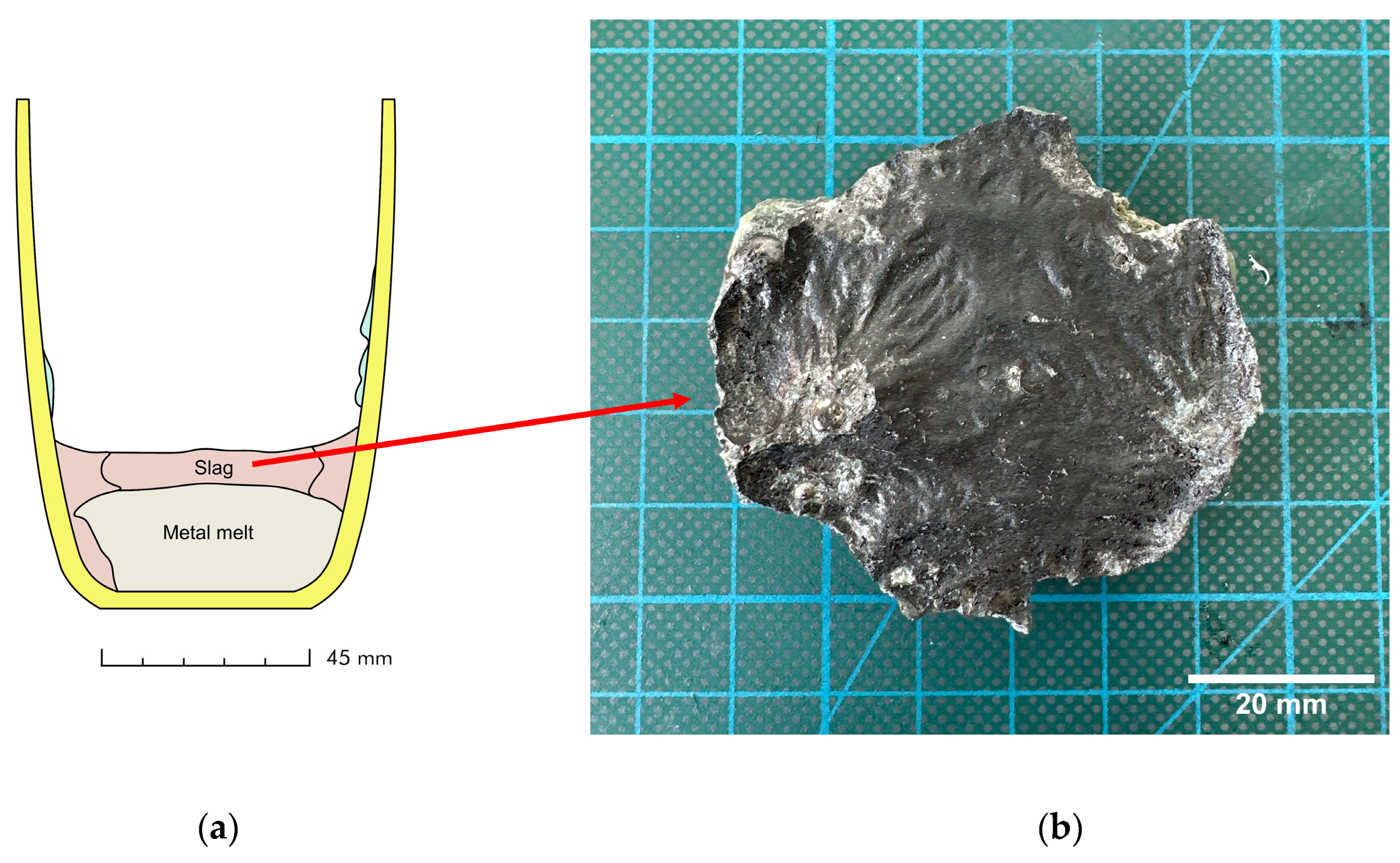
Figure 1. (a) Schematic representation of slag and melt formation in crucible; (b) intact slag body from center of crucible.
Minerals 15 00904 g001
Figure 2. Workflow for characterization of slag sample.
Minerals 15 00904 g002
Figure 3. Two-dimensional cross sections (taken from the center) of slag sample at different heights within image stack (top (A), middle (B), bottom (C)) by XCT analysis.
Minerals 15 00904 g003
Figure 4. (a) Three-dimensional visualization of metallic inclusions (blue) and pores (red) in slag body; (b) volume fractions of metallic inclusions and pores as function of distance to slag–metal interface.
Minerals 15 00904 g004
Figure 5. Volume-based probability density distribution with continuous representation through kernel density estimation of (a) metallic inclusions and (b) pores in the slag, visualized as a function of equivalent spherical diameter (xv) in µm and sphericity (ψ).
Minerals 15 00904 g005
Figure 6. (a) Relative amounts (g) of the equilibrium solid and solid solution phases during the cooling process. Major phases are represented by solid lines while minor phases (<10 g) are denoted by broken lines; (b) relative distribution of chromium into equilibrium phases as a function of temperature.
Minerals 15 00904 g006
Figure 7. Phase composition of slag by quantitative XRD (Rietveld method) and by modal mineralogy, as shown with empirical stoichiometric formulas, including minor impurities calculated from MLA results.
Minerals 15 00904 g007
Figure 8. Chromium distribution in different phases and distribution of phases in the slag.
Minerals 15 00904 g008
Figure 9. Example of slag particles analyzed by MLA. (a) Back-scattered electron images (A,C,E); (b) MLA false-color images (B,D,F) showing complexity of slag, intergrown phases, and associations of various phases in sample.
Minerals 15 00904 g009
Figure 10. Area-based particle size distribution Q2(x) of high Cr-containing spinel in slags determined by MLA.
Minerals 15 00904 g010
Table 1. Composition of utilized flux, liquidus temperature (Tliq), and slag basicity (B).
Composition (wt.%)Tliq (°C)B = (CaO + MgO)/SiO2 (w/w)
CaOSiO2Al2O3MgO
35.037.66.221.214531.5
Table 2. Feed and product weights and the calculated metal yield during the remelting of an EoL Jülich F10 SOC stack interconnect.
Feed (g)Product (g)Metal Yield = Metal/Sample (g/g)
SampleFluxMetalSlagUnrecovered
406.00105.89386.8056.1068.990.953
Table 3. Scanning and reconstruction parameters by Zeiss Xradia 510 Versa X-ray Microscopy: HE filter—high-energy filter; FBP—filtered back projection.
Parameters
ScanningSource–sample distance in mm 140
Sample–detector distance in mm 50
Acceleration voltage in keV 160
Electrical power in W 10
Filter in Zeiss Standard HE4
Optical magnification0.4×
Exposure time in s4.5
Camera binning2
Voxel size in µm 50.1
Number of projections 1601
Scan angle in degree360
ReconstructionReconstruction algorithmFBP
Gauss smoothing0.1
Beam hardening correction0.05
Table 4. Bulk chemical composition expressed in oxide forms determined by WD-XRF (in wt.%) including Loss-On-Ignition (LOI) value for information. The values are corrected using LOI value.
Sample Name LOICaOSiO2MgO Al2O3Fe2O3 ZrO2 BaO Cr2O3 MnO NiOCuO TiO2 SrO
in wt.%
IC0.5926.229.116.75.21.76.21.66.91.30.580.060.30.03
Disclaimer/Publisher’s Note: The statements, opinions and data contained in all publications are solely those of the individual author(s) and contributor(s) and not of MDPI and/or the editor(s). MDPI and/or the editor(s) disclaim responsibility for any injury to people or property resulting from any ideas, methods, instructions or products referred to in the content.