
Treatment of Metallurgical Residues by Chemical Modification, Reduction, and Phase Modification for Metal Recovery and Slag Utilization

 ,
,
Abstract
1. Introduction
- Regional and local optimization of material flows and cycles.
- Increased use of alternative cement constituents such as SCMs as a partial substitute for Portland cement clinker.
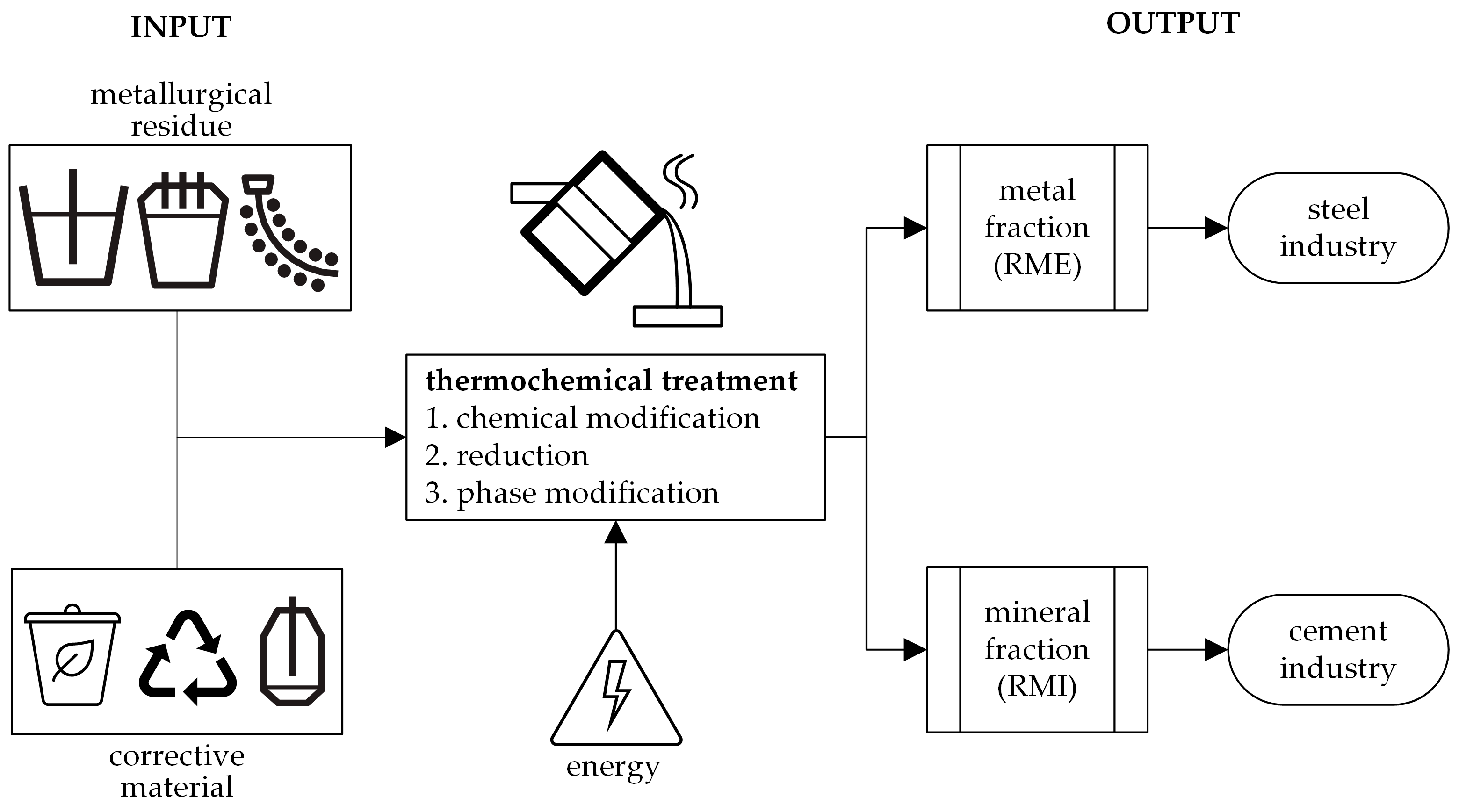
2. Materials and Methods
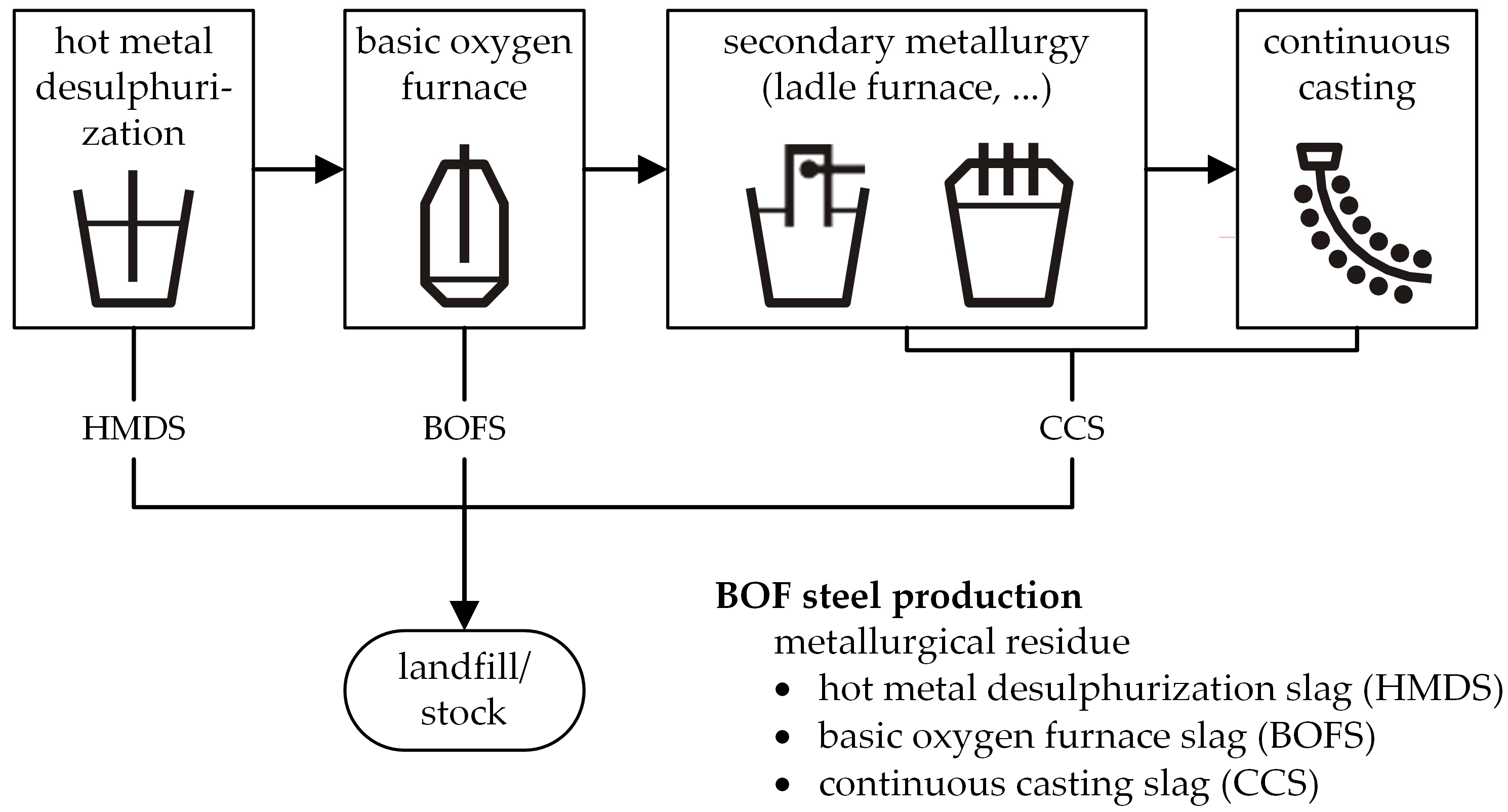
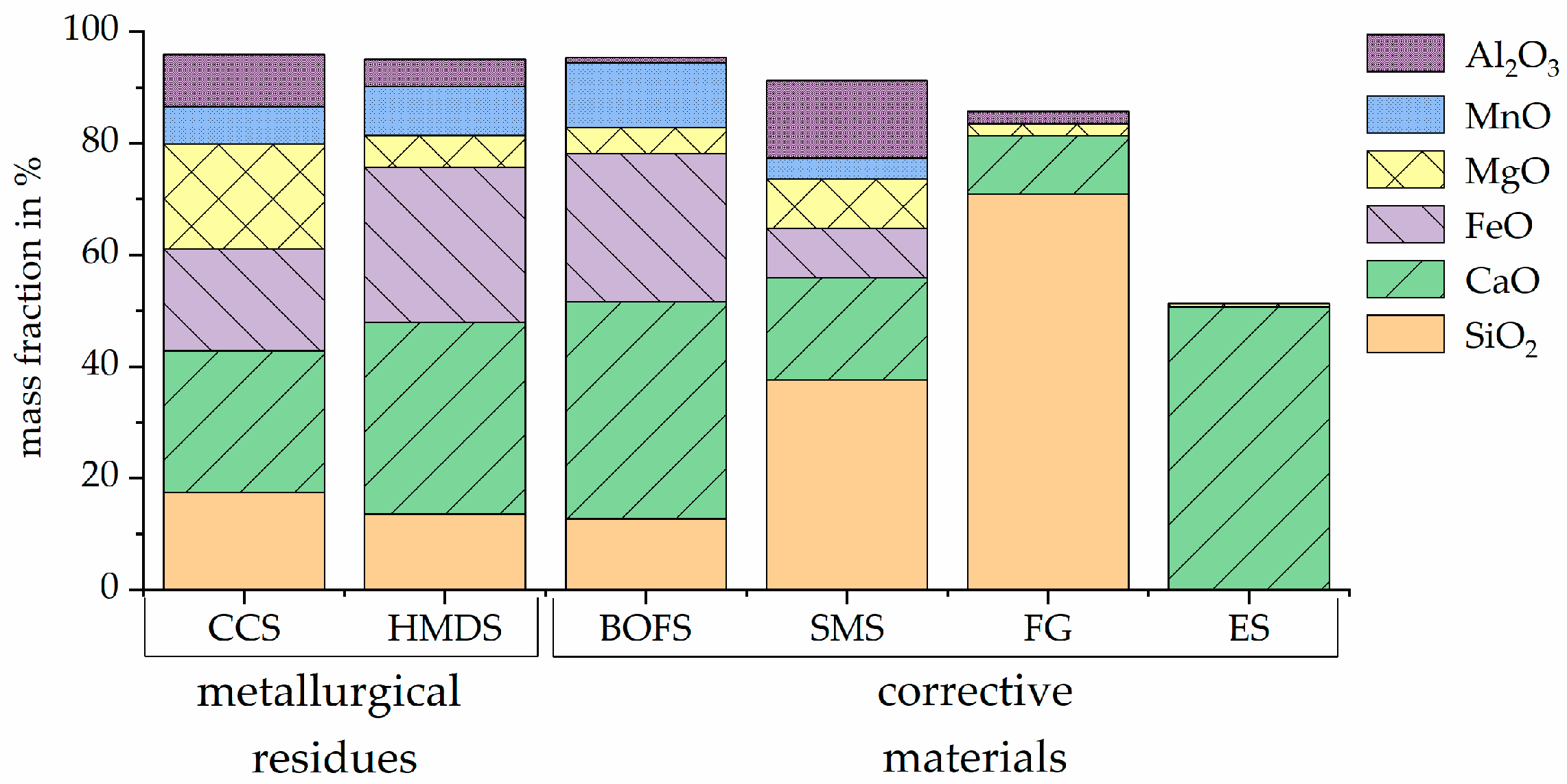
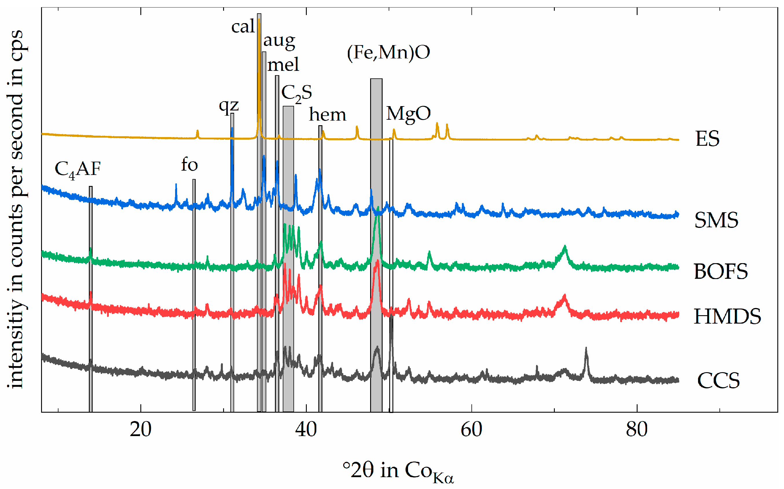
2.1. Metallurgical Residues/Corrective Material Description
2.2. Material Characterization
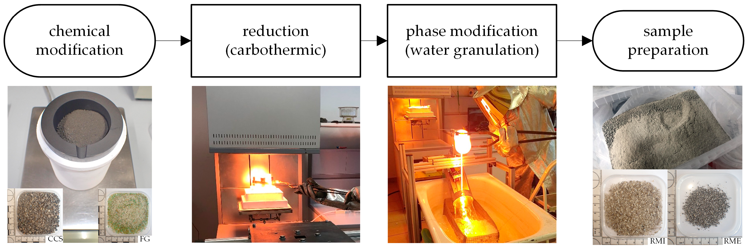
2.3. Experimental Setup
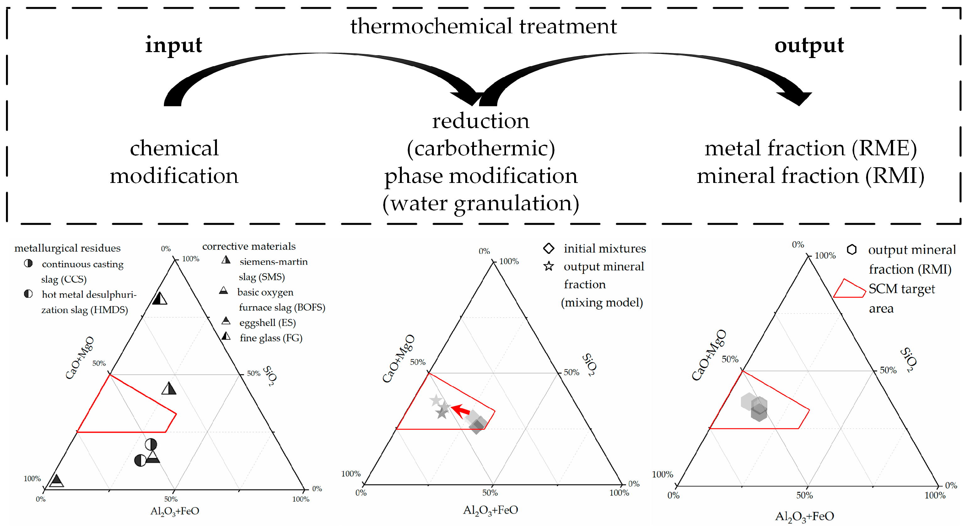
2.3.1. Chemical Modification
2.3.2. Reduction
2.3.3. Phase Modification
3. Results and Discussion
3.1. Reduction Agent—Carbon
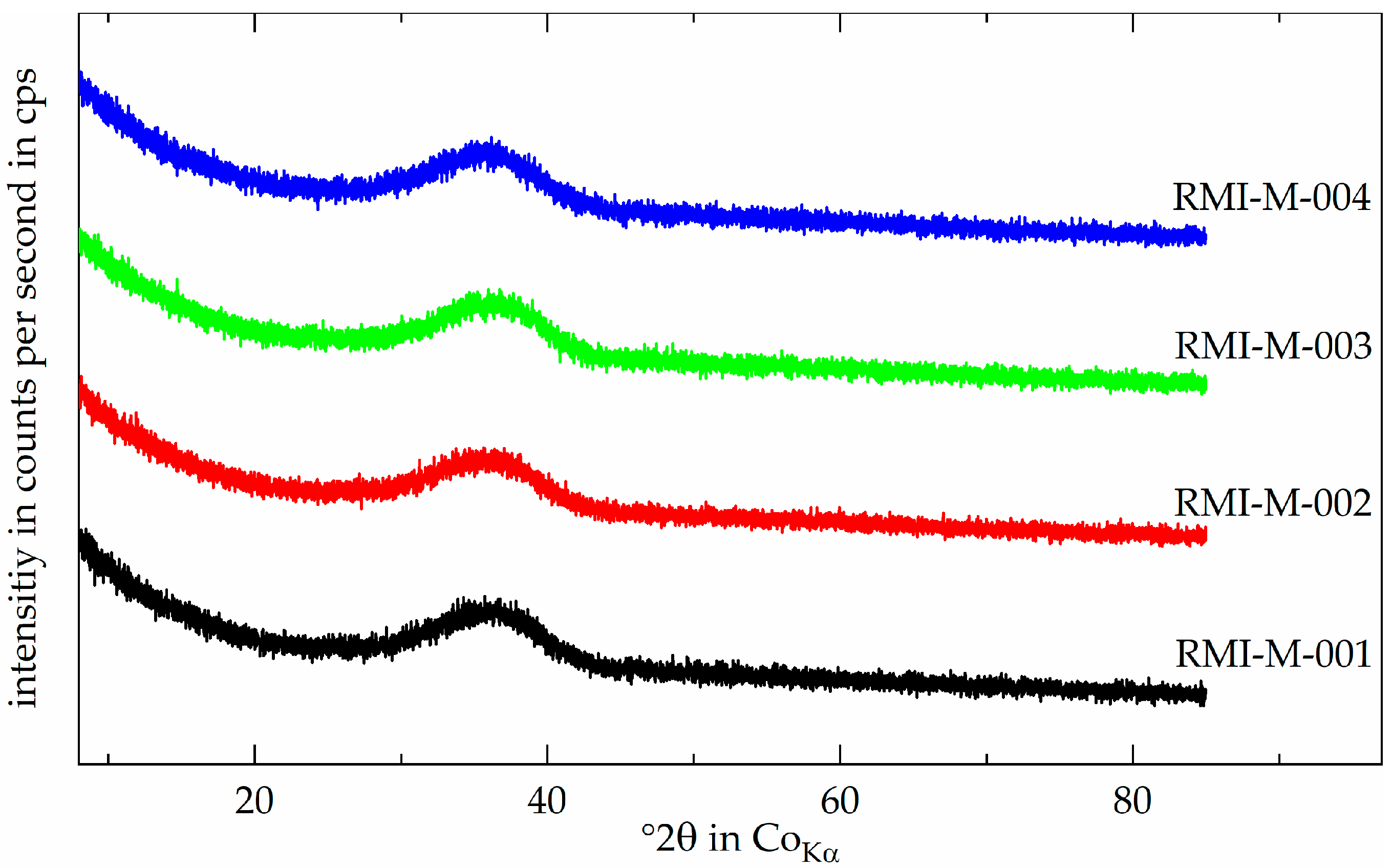
3.2. Output Mineral Fraction—RMI
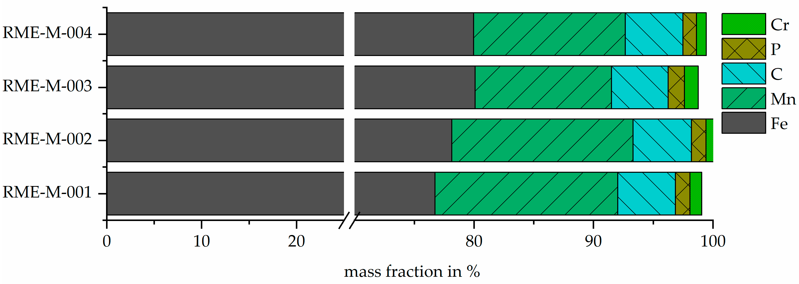
3.3. Output Metal Fraction—RME
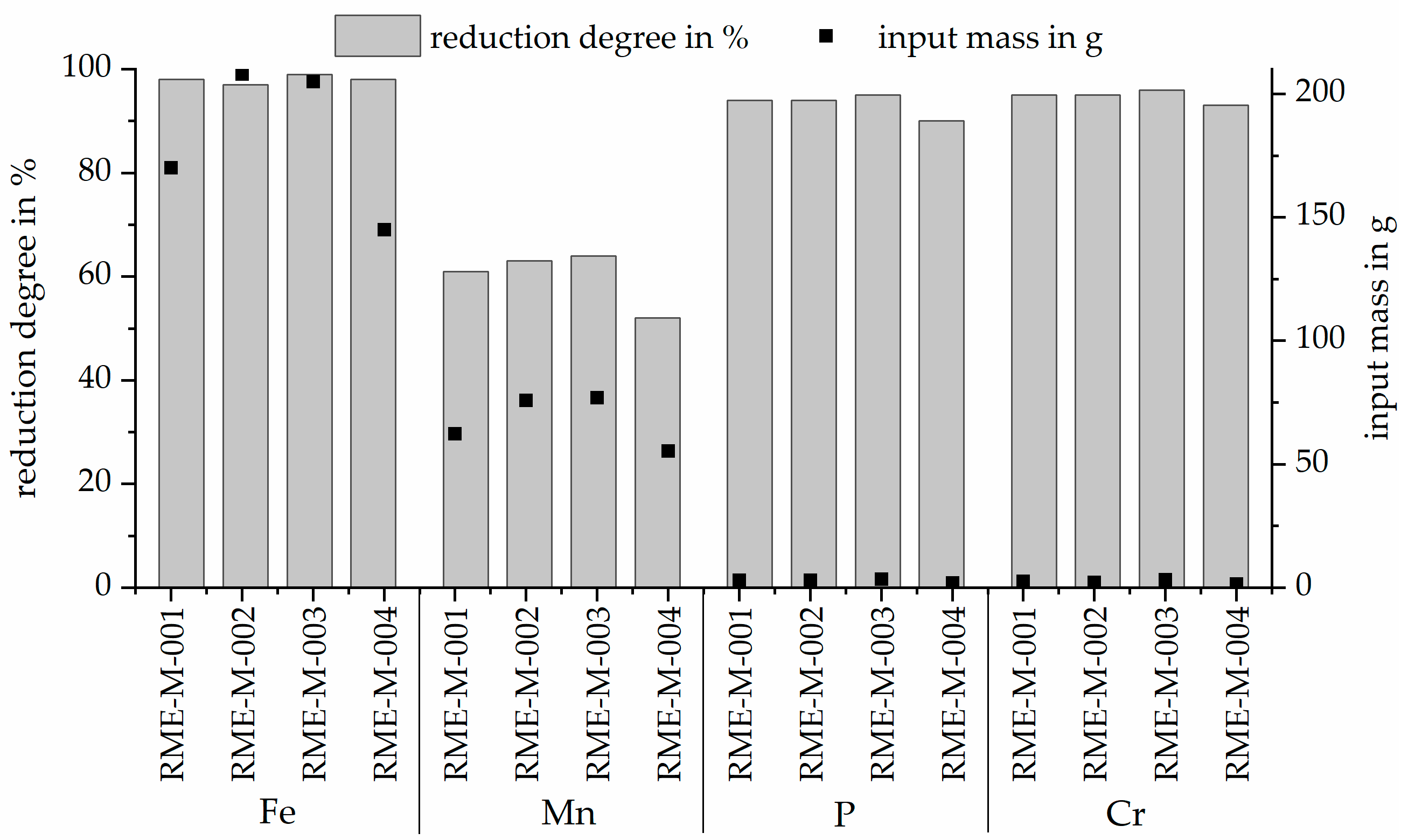
3.4. Reduction Degree
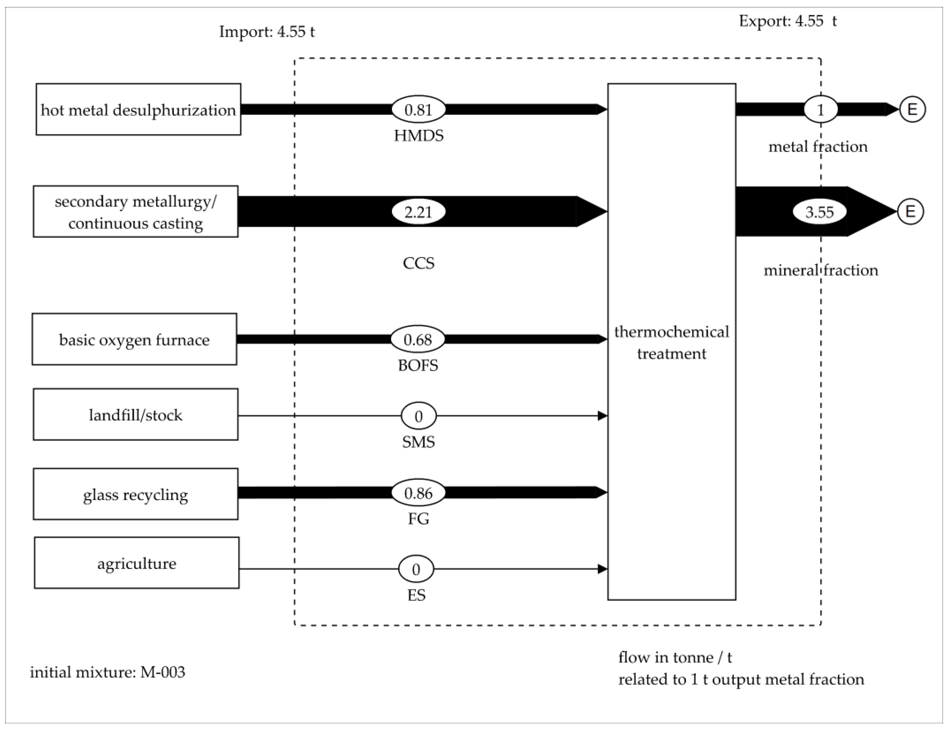
3.5. Material Flow Analysis
4. Conclusions
Author Contributions
Funding
Institutional Review Board Statement
Informed Consent Statement
Data Availability Statement
Acknowledgments
Conflicts of Interest
Abbreviations
| BOFS | basic oxygen furnace slag |
| CC | secondary metallurgy/continuous casting |
| CCS | continuous casting slag |
| CO | carbon monoxide |
| CO2 | carbon dioxide |
| ES | eggshell |
| FG | fine glass |
| GGBFS | ground granulated blast furnace slag |
| Gt | gigatonne |
| HMD | hot metal desulphurization |
| HMDS | hot metal desulphurization slag |
| LOI | loss on ignition |
| M | metal |
| MO | metal oxide |
| MM | mixing model |
| SCM | supplementary cementitious material |
| SMS | siemens-martin-slag/open-hearth furnace slag |
| t | tonne |
References
- International Energy Agency. Energy Technology Perspectives. 2020. Available online: https://iea.blob.core.windows.net/assets/7f8aed40-89af-4348-be19-c8a67df0b9ea/Energy_Technology_Perspectives_2020_PDF.pdf (accessed on 18 May 2022).
- Basson, E. World Steel in Figures. 2024. Available online: https://worldsteel.org/wp-content/uploads/World-Steel-in-Figures-2024.pdf (accessed on 9 March 2025).
- Chandel, S.S.; Singh, P.K.; Katiyar, P.K.; Randhawa, N.S. A Review on Environmental Concerns and Technological Innovations for the Valorization of Steel Industry Slag. Min. Metall. Explor. 2023, 40, 2059–2086. [Google Scholar] [CrossRef]
- voestalpine Stahl Donawitz GmbH. Umwelterklärung. 2018. Available online: https://www.voestalpine.com/stahldonawitz/static/sites/stahldonawitz/.downloads/de/VASD-Umwelterklaerung-2018_validiert_19.09.2018.pdf (accessed on 18 May 2020).
- Pilz, K.; Bertram, F.; Antrekowitsch, J.; Schneeberger, G. Verfahren zum Bearbeiten von Entschwefelungsschlacke. Available online: https://data.epo.org/publication-server/rest/v1.1/patents/EP3074540NWB1/document.html (accessed on 27 November 2014).
- Pichler, C.; Antrekowitsch, H.; Pilz, K. Thermische Behandlung von Entschwefelungsschlacke aus der Eisen- und Stahlindustrie. In Mineralische Nebenprodukte und Abfälle: Aschen, Schlacken, Stäube und Baurestmassen; Thomé-Kozmiensky, K.J., Thiel, S., Thomé-Kozmiensky, E., Friedrich, B., Pretz, T., Quicker, P., Senk, D.G., Wotruba, H., Eds.; TK: Neuruppin, Germany, 2017; pp. 223–237. ISBN 978-3-944310-35-0. [Google Scholar]
- Ponak, C.; Mally, V.; Windisch, S.; Holzer, A.; Raupenstrauch, H. Phosphorus Gasification during the Reduction of basic Oxygen Furnace Slags in a Novel Reactor Concept. Adv. Mater. Lett. 2020, 11, 20071535. [Google Scholar] [CrossRef]
- Windisch, S.; Ponak, C.; Mally, V.; Raupenstrauch, H. Phosphorrückgewinnung aus Klärschlammaschen mit dem RecoPhos-Prozess. Österr Wasser Abfallw 2020, 72, 421–428. [Google Scholar] [CrossRef]
- Bogala, M.R.; Zhang, M.; Reddy, R.G. Characterization of Steelmaking Desulfurization Slag. In Characterization of Minerals, Metals, and Materials 2015; Carpenter, J.S., Bai, C., Escobedo, J.P., Hwang, J.-Y., Ikhmayies, S., Li, B., Li, J., Monteiro, S.N., Peng, Z., Zhang, M., Eds.; Springer International Publishing: Cham, Switzerland, 2016; pp. 193–200. ISBN 978-3-319-48601-7. [Google Scholar]
- Schrama, F.N.H.; Ji, F.; Hunt, A.; Beunder, E.M.; Woolf, R.; Tuling, A.; Warren, P.; Sietsma, J.; Boom, R.; Yang, Y. Lowering iron losses during slag removal in hot metal desulphurisation without using fluoride. Ironmak. Steelmak. 2020, 47, 464–472. [Google Scholar] [CrossRef]
- Schrama, F.N.H.; Beunder, E.M.; Panda, S.K.; Visser, H.-J.; Moosavi-Khoonsari, E.; Hunt, A.; Sietsma, J.; Boom, R.; Yang, Y. Optimal hot metal desulphurisation slag considering iron loss and sulphur removal capacity part II: Evaluation. Ironmak. Steelmak. 2021, 48, 14–24. [Google Scholar] [CrossRef]
- Mensah, M.; Das, A. Metallurgical resource recovery from waste steelmaking slag from electric arc furnace. Environ. Technol. 2023, 44, 260–277. [Google Scholar] [CrossRef]
- Krammer, A.C.; Doschek-Held, K.; Steindl, F.R.; Weisser, K.; Gatschlhofer, C.; Juhart, J.; Wohlmuth, D.; Sorger, C. Valorisation of metallurgical residues via carbothermal reduction: A circular economy approach in the cement and iron and steel industry. Waste Manag. Res. 2024, 42, 797–805. [Google Scholar] [CrossRef]
- Proske, T.; Rezvani, M.; Palm, S.; Müller, C.; Graubner, C.-A. Concretes made of efficient multi-composite cements with slag and limestone. Cem. Concr. Compos. 2018, 89, 107–119. [Google Scholar] [CrossRef]
- Neufert, W.; Reuken, I.; Müller, C.; Palm, S.; Graubner, C.-A.; Proske, T.; Rezvani, M. Performance of clinker-efficient cements containing granulated blast furnace slag and limestone. Cem. Int. 2018, 16, 58–66. [Google Scholar]
- Palm, S.; Müller, C.; Proske, T.; Rezvani, M.; Graubner, C.-A. Concrete application of clinker-efficient cements. Adv. Cem. Res. 2019, 31, 225–234. [Google Scholar] [CrossRef]
- International Energy Agency. Iron and Steel Technology Roadmap. Available online: https://iea.blob.core.windows.net/assets/35cef3fa-e77d-47c8-9ed3-e1ccd2c8b5f9/Iron-Steel-Roadmap-Presentation.pdf (accessed on 17 May 2022).
- Eisner, P. Stoffliche Verwertung von Eisenhütten- und Stahlwerksschlacken als Bindemittelkomponenten—Entwicklung Eines Mischungsrechners (Recycling of Iron and Steel Slags as a Supplementary Cementitious Material (SCM)—Development of a Mixing Calculator). Bachelor’s Thesis, Montanuniversität, Leoben, Austria, 2023. [Google Scholar]
- Frey, D. Working Title—Vergleich von Berechnungsmodellen der Dynamischen Viskosität—Entwicklung Einer Toolbox zur Stofflichen Verwertung von Reststoffkombinationen (Comparison of Calculation Models for Dynamic Viscosity-Development of a Toolbox for the Utilisation of Residue Combinations). Bachelor‘s Thesis, Montanuniversität Leoben, Leoben, Austria, 2025. [Google Scholar]
- DIN 51730; Testing of Solid Fuels—Determination of Fusibility of Fuel Ash. Beuth Verlag GmbH: Berlin, Germany, 1998.
- Hesse Instruments. Brochure EM301—The Heating Microscope and EMI III Software. Available online: https://www.hesse-instruments.de/wp-content/uploads/2023/12/BRO_EM301_EN_160608.pdf (accessed on 9 March 2025).
- Wang, S.; Wen, Z.; Dou, R.; Xiao, Y.; Guan, Y.; Liu, X. Numerical study on the mixing process of hot desulfurization slag and converter steel slag. Case Stud. Therm. Eng. 2022, 40, 102561. [Google Scholar] [CrossRef]
- Kovtun, O.; Korobeinikov, I.; Shukla, A.K.; Volkova, O. Viscosity of BOF Slag. Metals 2020, 10, 982. [Google Scholar] [CrossRef]
- Durdán, M.; Terpák, J.; Laciak, M.; Kačur, J.; Flegner, P.; Tréfa, G. Hot Metal Temperature Prediction During Desulfurization in the Ladle. Metals 2024, 14, 1394. [Google Scholar] [CrossRef]
- Brooks, G.A.; Hasan, M.M.; Rhamdhani, M.A. Slag Basicity: What Does It Mean? In 10th International Symposium on High-Temperature Metallurgical Processing; Jiang, T., Hwang, J.-Y., Gregurek, D., Peng, Z., Downey, J.P., Zhao, B., Yücel, O., Keskinkilic, E., Padilla, R., Eds.; Springer International Publishing: Cham, Switzerland, 2019; pp. 297–308. ISBN 978-3-030-05954-5. [Google Scholar]
- Ehrenberg, A. Hüttensand—Ein leistungsfähiger Baustoff mit Tradition und Zukunft—Teil 2. Beton Inf. 2006, 46, 67–95. [Google Scholar]
- Austrian Standards Institute. Hüttensandmehl zur Verwendung in Beton, Mörtel und Einpressmörtel (Ground Granulated Blast Furnace Slag for Use in Concrete, Mortar and Grout)—Teil 1: Definition, Anforderungen und Konformatiätskriterien (Part 1: Definitions, Specifications and Conformity Criteria); Austrian Standards Institute: Vienna, Austria, 2006. [Google Scholar]
- Wang, G.; Zhang, H.; Wang, J.; Xue, Q. Improvement of Carbothermic Reduction of Copper Smelting Slag and Valuable Constituents Recovery. ISIJ Int. 2022, 62, 1–11. [Google Scholar] [CrossRef]
- Liu, C.; Huang, S.; Wollants, P.; Blanpain, B.; Guo, M. Valorization of BOF Steel Slag by Reduction and Phase Modification: Metal Recovery and Slag Valorization. Met. Mater. Trans. B 2017, 48, 1602–1612. [Google Scholar] [CrossRef]
- Yu, H.; Miki, T.; Sasaki, Y.; Nagasaka, T. Simultaneous Reduction of P2O5 and FeO from CaO–SiO2–FeO–P2O5 Synthesized Slag by Carbothermic Reduction. Met. Mater. Trans. B 2022, 53, 1806–1815. [Google Scholar] [CrossRef]
- Gatschlhofer, C. Phosphorus Behaviour During Carbothermal Reduction of Iron-, Chromium-, and Manganese-Rich Slags. Master’s Thesis, Montanuniversität Leoben, Leoben, Austria, 2022. [Google Scholar]
- Lin, B.; Wang, H.; Zhu, X.; Liao, Q.; Ding, B. Crystallization properties of molten blast furnace slag at different cooling rates. Appl. Therm. Eng. 2016, 96, 432–440. [Google Scholar] [CrossRef]
- Remus, R.; Roudier, S.; Aguado-Monsonet, M.A.; Delgado Sancho, L. Best Available Techniques (BAT) Reference Document for Iron and Steel Production: Industrial Emissions Directive 2010/75/EU: Integrated Pollution Prevention and Control; Publications Office: Luxembourg, 2013; ISBN 9279264753. [Google Scholar]
- Li, D.; Wu, X.; Shen, J.; Wang, Y. The influence of compound admixtures on the properties of high-content slag cement. Cem. Concr. Res. 2000, 30, 45–50. [Google Scholar] [CrossRef]
- Fu, X.; Hou, W.; Yang, C.; Li, D.; Wu, X. Studies on Portland cement with large amount of slag. Cem. Concr. Res. 2000, 30, 645–649. [Google Scholar] [CrossRef]
- Doschek-Held, K.; Raupenstrauch, H. Hochtemperaturprozesstechnik. Berg Hüttenmännische Monatshefte 2020, 165, 289–296. [Google Scholar] [CrossRef]
- Taylor, H. Cement Chemistry; Thomas Telford Publishing: London, UK, 1997; ISBN 0-7277-3945-X. [Google Scholar]
- Kurdowski, W. Cement and Concrete Chemistry; Springer: Dordrecht, The Netherlands, 2014; ISBN 978-94-007-7944-0. [Google Scholar]
- Blotevogel, S.; Steger, L.; Hart, D.; Doussang, L.; Kaknics, J.; Poirier, M.; Bornhöft, H.; Deubener, J.; Patapy, C.; Cyr, M. Effect of TiO2 and 11 minor elements on the reactivity of ground-granulated blast-furnace slag in blended cements. J. Am. Ceram. Soc. 2021, 104, 128–139. [Google Scholar] [CrossRef]
- Péra, J.; Ambroise, J.; Chabannet, M. Properties of blast-furnace slags containing high amounts of manganese. Cem. Concr. Res. 1999, 29, 171–177. [Google Scholar] [CrossRef]
- Krammer, A. Thermal Treatment and Cooling of Metallurgical Residues for Use as a Supplementary Cementitious Material. Master‘s Thesis, Montanuniversität, Leoben, Austria, 2022. [Google Scholar]
- Tossavainen, M.; Engstrom, F.; Yang, Q.; Menad, N.; Lidstrom Larsson, M.; Bjorkman, B. Characteristics of steel slag under different cooling conditions. Waste Manag. 2007, 27, 1335–1344. [Google Scholar] [CrossRef] [PubMed]
- Cencic, O.; Rechberger, H. Material Flow Analysis with Software STAN. J. Environ. Eng. Manag. 2008, 18, 3–7. [Google Scholar]
- Jovičević-Klug, M.; Souza Filho, I.R.; Springer, H.; Adam, C.; Raabe, D. Green steel from red mud through climate-neutral hydrogen plasma reduction. Nature 2024, 625, 703–709. [Google Scholar] [CrossRef] [PubMed]
- Ehrenberg, A. The steel production transformation process in Europe: New slag types will substitute granulated blast furnace slag. Zem.-Kalk-Gips 2023, 76, 86–97. [Google Scholar]
- Ehrenberg, A.; Romero Sarcos, N.; Hart, D.; Bornhöft, H.; Deubener, J. Influence of the Thermal History of Granulated Blast Furnace Slags on Their Latent Hydraulic Reactivity in Cementitious Systems. J. Sustain. Metall. 2020, 6, 207–215. [Google Scholar] [CrossRef]
- Steindl, F.R.; Doschek-Held, K.; Weisser, K.; Juhart, J.; Grengg, C.; Wohlmuth, D.; Mittermayr, F. Mineral Residues and By-Products Upcycled into Reactive Binder Components for Cementitious Materials. In International RILEM Conference on Synergising Expertise Towards Sustainability and Robustness of Cement-Based Materials and Concrete Structures: SynerCrete’23—Volume 2, 1st ed.; Jędrzejewska, A., Kanavaris, F., Azenha, M., Benboudjema, F., Schlicke, D., Eds.; Springer: Cham, Switzerland, 2023; pp. 153–164. ISBN 978-3-031-33186-2. [Google Scholar]
- Steindl, F.R.; Radinger, S.; Hassan, A.; Rudic, O.; Weisser, K.; Krammer, A.; Doschek-Held, K.; Ratz, B.; Zögl, I.; Raič, S.; et al. Thermally Treated Residues and By-Products as Components of Waste-Based Alkali-Activated Materials. In Proceedings of the RILEM Spring Convention and Conference 2024, Milan, Italy, 7–12 April 2024; Ferrara, L., Muciaccia, G., Trochoutsou, N., Eds.; Springer: Cham, Switzerland, 2025; pp. 53–61, ISBN 978-3-031-70276-1. [Google Scholar]

| Material Type | Process | Material |
|---|---|---|
| metallurgical residue | hot metal desulphurization | hot metal desulphurization slag (HMDS) |
| secondary metallurgy/continuous casting | continuous casting slag (CCS) | |
| corrective material | basic oxygen furnace | basic oxygen furnace slag (BOFS) |
| landfill/stock | siemens-martin-slag (SMS) | |
| glass recycling | fine glass (FG) | |
| agriculture | eggshell (ES) |
| Parameter | SMS | FG | ES | |
|---|---|---|---|---|
| mass fraction in % | K2O | 1.9 | 0.9 | 0.02 |
| Na2O | 0.45 | 12.3 | 0.06 | |
| SO3 | 2.4 | 0.08 | 0.10 | |
| LOI in % | 2.3 | 0.53 | 47.3 |
| Parameter | Material | Measured | Min | Max | Literature |
|---|---|---|---|---|---|
| flow temperature in °C | CCS | 1388–1396 | 1 | ||
| HMDS | 1397–1446 | 1280 | 1413 | [22] | |
| BOFS | 1399–1406 | 1145 | 1515 | [23] | |
| SMS | 1291–1352 | 1500 | [24] |
| Parameter | Min | Max | |
|---|---|---|---|
| mass fraction (w) in % | 25 * | 100 * | |
| 0.0 * | 13.0 * | ||
| 2.0 * | 17.0 * | ||
| basicity B2 [25] basicity B3 [25] basicity B4 [25] | 0.87 * | 1.6 * | |
| 1.0 * | 2.0 * | ||
| 0.60 * | 1.20 * | ||
| production ratio | CC/REE | 2.8 | 3.2 |
| material ratio in % | BOFS | 0.0 | 4.0 |
| reduction degree in % (assumption) | Fe | 0.98 # | - |
| Mn | 0.8 # | - | |
| Cr | 0.8 # | - |
| Material Mass in g | |||||||
|---|---|---|---|---|---|---|---|
| Sample | CCS | HMDS | SMS | BOFS | FG | ES | Carbon |
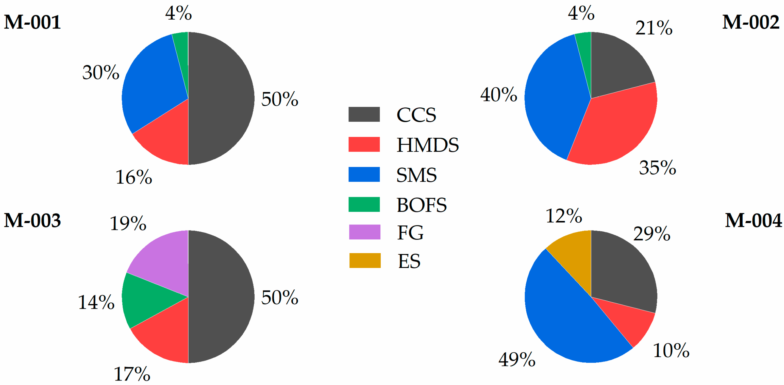
| M-001 | 637 | 200 | 366 | 55 | - | - | 47 |
| M-002 | 274 | 457 | 522 | 52 | - | - | 48 |
| M-003 | 630 | 225 | - | 187 | 241 | - | 46 |
| M-004 | 371 | 132 | 629 | - | - | 153 | 34 |
| Parameter | Min | Max | RMI- M-001 | RMI- M-002 | RMI- M-003 | RMI- M-004 | |
|---|---|---|---|---|---|---|---|
| mass fraction (w) in % | 25 | 100 | 30.5 | 33.3 | 34.5 | 33.1 | |
| 0 | 13 | 14.4 | 12.7 | 8.5 | 13.5 | ||
| 2.0 | 17.0 | 17.3 | 13.4 | 16.9 | 14.3 | ||
| basicity B2 basicity B3 basicity B4 | 0.87 | 1.6 | 1.08 | 1.05 | 0.99 | 1.02 | |
| 1 | 2 | 1.65 | 1.45 | 1.48 | 1.46 | ||
| 0.60 | 1.20 | 1.05 | 1.04 | 0.99 | 1.02 |
Disclaimer/Publisher’s Note: The statements, opinions and data contained in all publications are solely those of the individual author(s) and contributor(s) and not of MDPI and/or the editor(s). MDPI and/or the editor(s) disclaim responsibility for any injury to people or property resulting from any ideas, methods, instructions or products referred to in the content. |
© 2025 by the authors. Licensee MDPI, Basel, Switzerland. This article is an open access article distributed under the terms and conditions of the Creative Commons Attribution (CC BY) license (https://creativecommons.org/licenses/by/4.0/).
Share and Cite
Doschek-Held, K.; Krammer, A.C.; Steindl, F.R.; Gatschlhofer, C.; Raonic, Z.; Wohlmuth, D. Treatment of Metallurgical Residues by Chemical Modification, Reduction, and Phase Modification for Metal Recovery and Slag Utilization. Minerals 2025, 15, 408. https://doi.org/10.3390/min15040408
Doschek-Held K, Krammer AC, Steindl FR, Gatschlhofer C, Raonic Z, Wohlmuth D. Treatment of Metallurgical Residues by Chemical Modification, Reduction, and Phase Modification for Metal Recovery and Slag Utilization. Minerals. 2025; 15(4):408. https://doi.org/10.3390/min15040408
Chicago/Turabian StyleDoschek-Held, Klaus, Anna Christine Krammer, Florian Roman Steindl, Christoph Gatschlhofer, Zlatko Raonic, and Dominik Wohlmuth. 2025. "Treatment of Metallurgical Residues by Chemical Modification, Reduction, and Phase Modification for Metal Recovery and Slag Utilization" Minerals 15, no. 4: 408. https://doi.org/10.3390/min15040408
APA StyleDoschek-Held, K., Krammer, A. C., Steindl, F. R., Gatschlhofer, C., Raonic, Z., & Wohlmuth, D. (2025). Treatment of Metallurgical Residues by Chemical Modification, Reduction, and Phase Modification for Metal Recovery and Slag Utilization. Minerals, 15(4), 408. https://doi.org/10.3390/min15040408