Article

Using Time-Series Videos to Quantify Methane Bubbles Flux from Natural Cold Seeps in the South China Sea

1
CAS Key Laboratory of Ocean and Marginal Sea Geology, South China Sea Institute of Oceanology, Chinese Academy of Sciences, Guangzhou 510301, China
2
Laboratory for Marine Mineral Resources, Qingdao National Laboratory for Marine Science and Technology, Qingdao 266061, China
3
Innovation Academy of South China Sea Ecology and Environmental Engineering, Chinese Academy of Sciences, Guangzhou 510301, China
4
Southern Marine Science and Engineering Guangdong Laboratory (Guangzhou), Guangzhou 511481, China
5
Shanghai Engineering Research Center of Hadal Science and Technology, College of Marine Sciences, Shanghai Ocean University, Shanghai 201306, China
6
MNR Key Laboratory of Marine Mineral Resources, Guangzhou Marine Geological Survey, Ministry of Natural Resources, Guangzhou, Guangdong 510075, China
*
Author to whom correspondence should be addressed.
Minerals 2020, 10(3), 216; https://doi.org/10.3390/min10030216
Submission received: 18 December 2019 / Revised: 22 February 2020 / Accepted: 24 February 2020 / Published: 27 February 2020
(This article belongs to the Special Issue Marine Geology and Minerals)

Abstract

:
Natural cold seeps are an important source of methane and other greenhouse gases to the ocean and atmosphere in the marine environment. Accurate quantification of methane bubble fluxes from cold seeps is vital for evaluating their influence on the global methane budget and climate change. We quantified the flux of gas bubbles released from two natural cold seep sites in the South China Sea: one seep vent in the Haima cold seeps (1400 m depth) and three seep vents at Site F (1200 m depth). We determined bubble diameter, size distribution, and bubble release rate using image processing techniques and a semiautomatic bubble-counting algorithm. The bubble size distributions fit well to log-normal distribution, with median bubble diameters between 2.54 mm and 6.17 mm. The average bubble diameters and release rates (4.8–26.1 bubbles s−1) in Site F was lower than that in Haima cold seeps (22.6 bubbles s−1), which may be attributed to a variety of factors such as the nature of the gas reservoir, hydrostatic pressure, migration pathways in the sediments, and pore size. The methane fluxes emitted at Haima cold seeps (12.6 L h−1) and at Site F (4.9 L h−1) indicate that the Haima and Site F cold seeps in the South China Sea may be a source of methane to the ocean. However, temporal variations in the bubble release rate and the geochemical characteristics of the seeps were not constrained in this study due to the short observational time interval.

1. Introduction

Natural cold seeps occur worldwide and are an important source of methane to the ocean water column and atmosphere [1,2,3,4,5,6]. Cold seeps represent an important pathway by which natural gases, primarily methane, are released from the lithosphere into the hydrosphere and atmosphere [7]. Methane is a potent greenhouse gas and has attracted attention because of its strong impact on Earth’s radiative balance [8,9,10]. The methane budget from natural and anthropogenic contributions is estimated to be 554 ± 56 Tg CH4 yr−1 (542–852 Tg yr−1), albeit with uncertainties exceeding 10% [11,12]. It is estimated that approximately 20 Tg yr−1 of methane is discharged into the atmosphere through marine seeps [9,13], i.e., approximately half of global geological emissions (40–60 Tg CH4 yr−1) [13,14,15]. There are significant uncertainties associated with these values due to the lack of quantitative studies of seepage flux and the scarcity of direct in situ observations of natural bubble seeps in the water column. As such, additional studies are needed to obtain more accurate estimates of methane fluxes from cold seeps and thus improve understanding of the contribution of cold-seep methane fluxes to global carbon cycles and climate change. However, methane fluxes to the ocean and atmosphere via seep pathways are particularly difficult to quantify because of limitations associated with technology and logistics.
Cold seeps are typically associated with a variety of chemosynthetic fauna (such as tubeworms and mussels), authigenic carbonates, and gas hydrates generated through the physical and chemical changes in the sediments [16,17,18,19,20,21]. Rates of methane release from natural cold seeps are highly variable and poorly constrained. Furthermore, existing global estimates of methane input to the oceans are crudely extrapolated from limited measurements at known seeps and therefore rely heavily on the accuracy of data measured in situ [22]. To address these problems, many observational instruments (turbine seep tent and gas flux measuring devices) and bubble and plume models have been developed to quantify bubble rates and bubble fluxes. In addition, underwater camera systems can be used to observe bubble characteristics (bubble size, bubble rise velocity, bubble release frequency) by capturing high definition videos that can be analyzed [23,24]. Furthermore, bubble and plume models can quantify total methane fluxes by simulating evolving bubble size, gas composition, and plume height [25,26]. To accurately quantify methane input to the ocean and atmosphere, the characteristics of gas bubbles released from natural cold seeps worldwide have been increasingly investigated [23,27,28,29,30,31,32,33]. Until now, due to the limited duration of videos captured (seconds to minutes), many studies have only estimated bubble size, rise velocity, behavior, and fate of bubbles and have not been able to determine temporospatial changes in the various parameters [2,3,4,5,34,35,36,37,38]. This is largely because power supply to the camera systems has limited longevity [23,27,32,33], meaning that it has not yet been possible to capture this temporospatial variability or other parameters such as biological effects. High-definition video systems have not formerly been applied in studies of bubble size and flux in other typical cold seep areas such as those in the South China Sea (SCS), Black Sea, and the Mediterranean.
SCS cold seeps have received increasing scientific attention since their discovery and are now among the best-studied seep sites globally [39]. In the past three decades, over 30 cold seeps have been discovered on the SCS continental slope, including the only two known active seep sites, Site F (also named Formosa Ridge by [40]) and the Haima cold seep (Figure 1) [41]. However, until now, bubble release rates and bubble flux at these two active cold seeps have not been quantified. Here, we report an investigation of bubble size distribution, release rate, and flux at Site F and Haima cold seeps in the northern part of the SCS. Bubble size is influenced by vent and plume size, the diameter of the pore openings, and surfactants coating the bubble [2]. The reservoir fill or hydrostatic pressure can also affect bubble release rate [17,42,43]. Here we present the first observations of gas bubble characteristics at these distinct cold seep sites, quantify the associated methane bubble fluxes, and discuss the dynamics behind factors controlling variations in bubbles flux in the SCS.

2. Study Areas

2.1. Site F

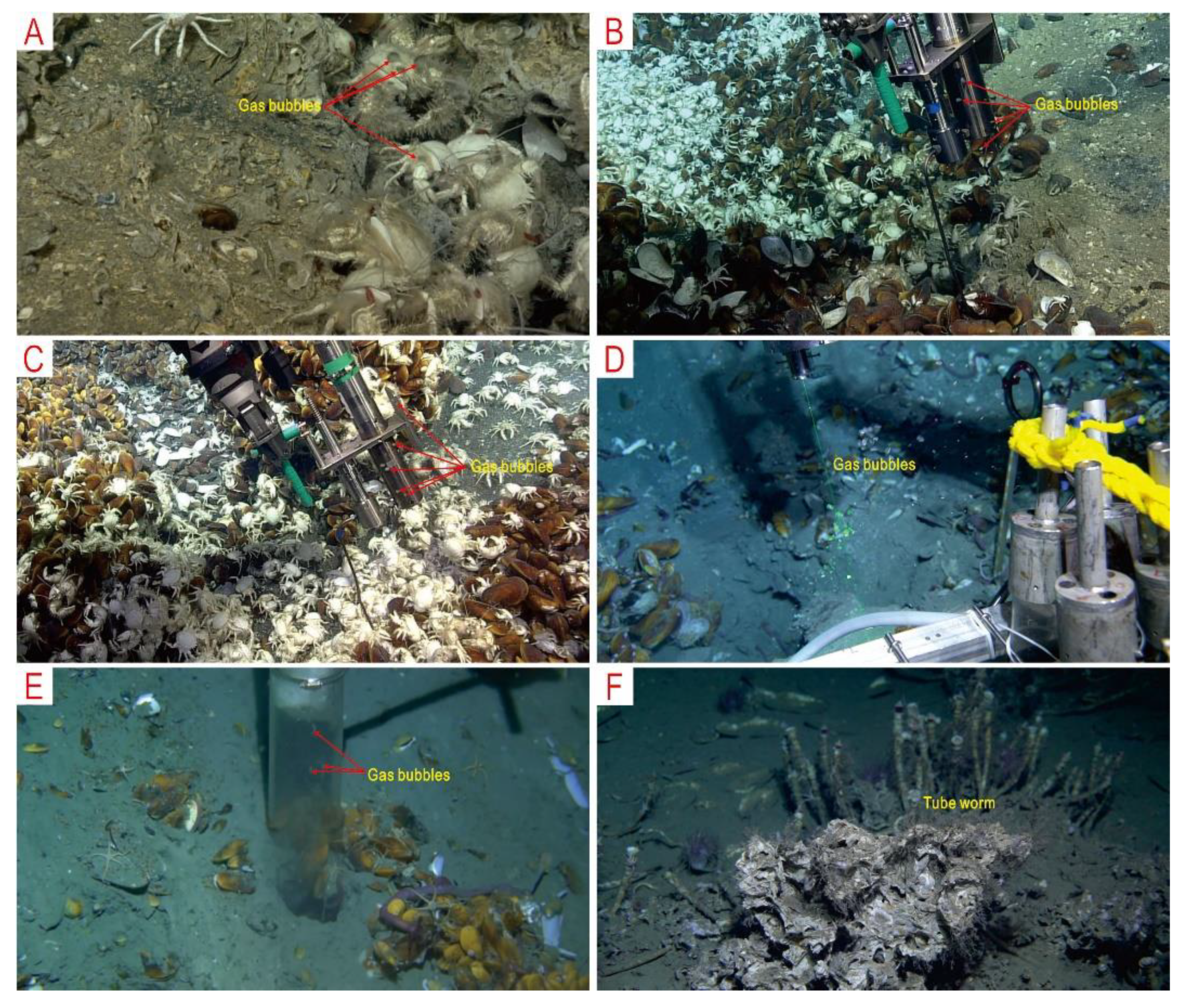
Site F covers an area of about 100 m × 140 m at a water depth of 1120 m on the northeastern continental slope of the SCS (Figure 1). This area has become an important natural laboratory for researching natural seeps since the first discovery of an active gas plume on top of the ridge [39,40,44,45]. During the Tan Kah Kee expedition of 16 April to 15 May 2018, three individual natural gas seep vents (referred to as Site F seep 1, Site F seep 2, and Site F seep 3) were discovered and observed using the remotely operated vehicle (ROV) ROPOS. These three active seep vents are no more than 13 m apart on the Southern summit of the Formosa ridge (Figure 1C) and presumably share the same shallow methane source. Localized chemosynthetic fauna including densely packed mussels (Bathymodiolus platifrons), white galatheid crabs (Shinkaia crosnieri), brittle stars, and carbonate blocks are common (Figure 2A–C). Bacterial mats covering the surrounding sediments were also apparent during the ROV deployment.

2.2. Haima

Haima cold seep is an active site at a water depth of 1370–1390 m in the southwestern part of Qiongdongnan Basin (Figure 1B). This area itself is part of the Southern Uplift Belt of Qiongdongnan Basin, and the Xisha Block lies to the south [46]. Two active seep vents were discovered and sampled in the study area using the ROV Haima during cruises in 2018 and 2019. Haima seep 1 is ~7 km northwest of Haima seep 2 [41,47]. A bathymetric map of the study area reveals a relatively flat topography (Figure 1B). Localized chemosynthetic fauna including mussels (Gigantidas haimaensis n. sp.), brittle stars, and carbonate blocks are common around the seep vents (Figure 2E). Gas hydrates in mounds covered by sediment were found nearby on the seafloor. Tubeworms were also found in the Haima cold seeps, but at quite a large distance from Haima seep 1 (Figure 2F).

3. Methods

3.1. CTD and Methane Sensor

The ambient environments at the Haima cold seeps and Site F were characterized using a CTD sensor designed by RBR Ltd., Ottawa, ON, Canada (for measuring conductivity, temperature, and depth) mounted on the ROV used at each site. The HydroCTM methane sensor (HYDROC GmbH, Flensburg, Germany) was mounted on the ROV Haima and used to locate the bubble release points by measuring methane concentrations in bottom waters.

3.2. Camera Properties and Deployment

The stereoscopic imaging system consisted of two integrated high-speed cameras in individual pressure housings, image lighting, subsea power and communication managed by a third pressure housing, and shipboard control. A photographic presentation system was mounted on ROVs ROPOS and Haima. The high-speed high-resolution Phantom CMOS Miro-M340 cameras (Vision research Ltd., Wayne, NJ, USA) mounted on ROPOS gave a full resolution of 1920 × 1080 pixels with a frame rate of 30 frames s−1. The high-definition camera with a SONY FE PZ 28–135 mm f/4 OSS lens (Sony Ltd., Beijing, China) mounted on Haima gave a full resolution of 1920 × 1080 pixels with a frame rate of 60 frames s−1.
These two high-definition cameras were enclosed in underwater pressure housing rated at 4500 m water depth [23,33], and connected to the storage control center in another pressure housing by a SubConn cable. The storage control center was mounted in the center of the ROV and connected to the ROV’s multiplexer. The two cameras were provided with 24 V DC power and a bi-directional isolated synchronization signal line as a master-slave trigger mode through wiring to the storage control center. The trigger signal was processed using software developed by the manufacturer and controlled over an Ethernet connection to the computer. In this mode, the trigger delay of the camera was ~1 ms. Videos were stored in a 1 TB flash drive attached to the camera inside the pressure housing. The data was transferred from the flash drive to a computer via the Ethernet connection.
The high-definition camera mounted on ROV ROPOS was positioned approximately 30 cm from Site F seep 1 on 19 April 2018, and recorded a video clip for 9 min (Figure 2A). On 20 April 2018, the same ROV visited Site F seep 2 and seep 3 where the camera was deployed ~40 cm from each and captured three video clips lasting one hour (Figure 2B,C). Haima seep 1 and seep 2 were visited by ROV Haima on 29 April 2018, and 6 May 2019, respectively. The camera mounted on ROV Haima was positioned ~30 cm from the bubble release points (Figure 2D,E) and recorded one 4-min video clip at Haima seep 2 and four 5-min video clips at seep 1 (Table 1).

3.3. Bubble Size Measurements

Bubble data obtained from the videos were captured in a two-dimensional plane via a high-definition camera located less than 50 cm from the cold seep vents (Table 1). Due to parallax, camera positioning, and timing, there was a significant reduction in the accuracy of the bubble size and bubble flux measurements. Due to parallax and poor lighting, we were unable to obtain bubble size measurements at Haima seep 2 (Figure 2E). However, we were able to measure bubble size or estimate bubble flux at Site F seep 2 and seep 3, and Haima seep 1 except for Site F seep 1, because, at Site F seep 1, we could not accurately convert pixels to mm because there was no measurement scale of known length or swing arm in the images for reference (Figure 2A). However, at Site F seep 2 and seep 3, we were able to convert pixels to mm using the swing arms of ROV ROPOS as a reference because they were in the field of view and in the bubble stream (Figure 2B,C). At Haima seep 1, we could determine the pixel-to-mm conversion as we had inserted a stainless steel scale in line with the bubble stream (Figure 2D).
For each image data set, the pixel-to-mm conversion was adjusted accordingly, and ImageJ® software (ImageJ 1.51j8, National Institute of Health, Wayne, NJ, USA) was used to estimate bubble dimensions by measuring their major and minor axes [24]. The smallest measurable bubble size was ~1 mm. For Site F seep 2, 966 bubbles were measured from 1128 images analyzed. For Site F seep 3, 344 bubbles were measured from 2378 images analyzed. For Haima seep 1, a total of 626 bubbles were measured from 1680 images analyzed.
To obtain the volume of a single bubble, the bubble radius was calculated using the major and minor axes of a spheroidal bubble as described in [48]:
r = ( a 2 b ) 8 3
where a is the semi-major axis, b is the semi-minor axis, and r is the radius of the spheroidal bubble. We calculated r using Equation (1) and estimated the volume, V, of the bubble from V = (4/3)πr3. Generally, we assumed that gas bubbles contained 100% methane for the purposes of the methane flux calculations, although it is likely that small amounts of ethane or carbon dioxide were also present. Based on this assumption, we calculated the amount, n, of methane within a volume, V, and corrected for the compressibility factor of methane at any given depth and pressure as follows:
P V = n R T Z
where P is the absolute pressure in MPa, V is the molar volume of the bubble in cm3, R is the universal gas constant equal to 8.314 cm3 MPa mol−1 K−1, T is the temperature of the water (K), and Z is the compressibility factor of methane, which was calculated using the van der Waals equation of state based on the given pressure and temperature. Based on Equation (2), Z = 0.792 (for a temperature of 3.5 °C) at Site F and 0.783 (for a temperature of 3.1 °C) at the Haima cold seeps [49].
Bubble rise velocity can be affected by bubble size, bubble oscillation, sea currents, bubble release rate, upwelling effects, bubble interface mobility, and surface cleanliness [2,33,50]. Additionally, when the bubbles are rising, bubble size decreases due to pressure changes, bubble oscillation, and gas exchange rates [51]. Therefore, it was necessary to choose a suitable and consistent height (50 cm) above the bubble release points for measuring bubble size in order to minimize discrepancies in the measurements.

3.4. Semi-Automatic Bubble Counting Algorithm

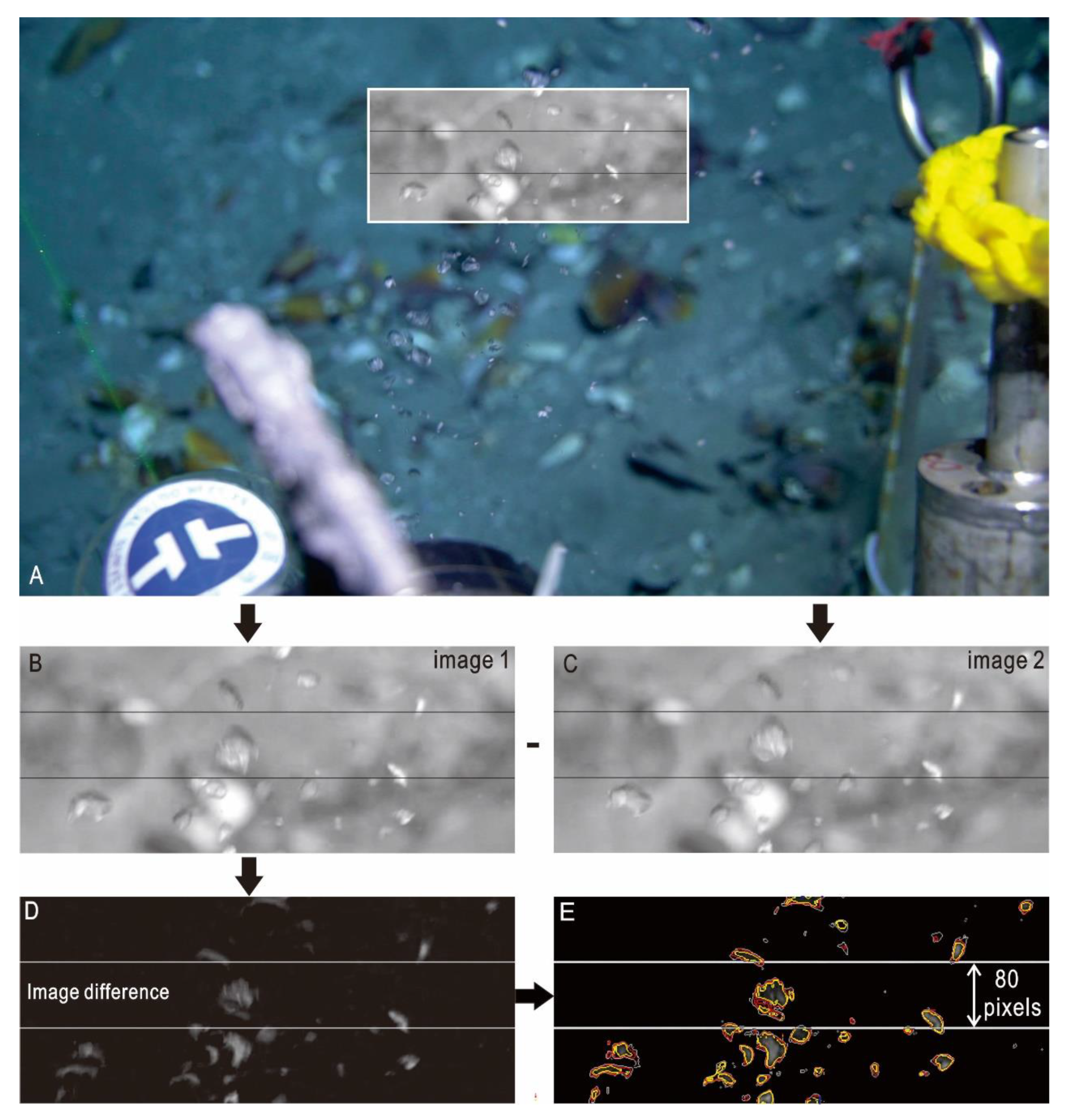
A semi-automatic bubble counting algorithm (SABCA) was adopted to determine bubble count and release rates from the video data [23]. This method is suitable for discrete vents with small bubble streams, as is commonly the case. We investigated bubble flow by recording videos for only a few minutes, which could then be cut into several video clips of 10 s (Table 1). Prior to running SABCA, the video data were converted to still frame images and six selected variables were assigned through the following steps: (1) all video clips were converted to still frame images using the video-to-pic program available in MATLAB software (2015a, The MathWorks, Inc., Natick, MA, USA), allowing us to analyze multiple images and determine average bubble release values per clip (Table 1); (2) a suitable position for bubble counting in a cropped window was determined using ImageJ® 1.51j8 software (white box, Figure 3A); (3) the counting region within the cropped window was adjusted based on the data set and bubble speed (white horizontal lines in Figure 3B,D); (4) the bubble rising speed in pixels s−1 and bubble height in pixels within the counting region were determined using ImageJ® 1.51j8 software; (5) high, medium, and low threshold values were manually determined using MATLAB. Once variables had been determined, their consistency was checked through cross-checking throughout the data set.
To accurately count bubbles, the cropped window was predetermined at each of the cold seep vents according to camera position and bubble rising velocity. If the camera was stationary, the cropped window remained unchanged, and this method was viable under various conditions. We used two white horizontal lines in the cropped window to minimize the error in bubble counting, as the count could be influenced by the overlap between bubbles, bubbles exiting the frame, and the presence of shadows (Figure 3B). The speed at which the bubbles moved through the frame was calculated using an approximate bubble pixel height and a constant average rising velocity within each dataset. A properly sampling interval between frames analyzed by the semi-automated algorithm can make a completely new set of continuous bubbles analyze between consecutive images, avoiding double counting or oversampling bubble counts between consecutive frames (Figure 3B,C). Our video data set sampled at 30 or 60 frames s−1, which was sufficient to determine the number of faster-moving bubbles without undersampling.
Finally, the corresponding pixel values for the converted consecutive grayscale images were subtracted to remove the unchanging parts of the image background (e.g., sediments, mussels, and water column). The resulting image showed that the bright spots between frames are bubbles (Figure 3D). Three threshold values (high, medium, and low) were defined manually to identify each bubble based on differences in bubble brightness caused by bubble motion, blurring, shadows, and background noise (Figure 3E). When all the steps had been completed, the automated bubble counting algorithm could be run and bubble counts generated [24], as follows:
B = [ r = 1 N ( i = 1 I C t r i ) ] × F ( N × I )
where B is the average number of bubbles per second in a given video clip at threshold t, N is the number of horizontal pixel lines in the counting region, I is the number of frames, tCri is the bubble count on line r of image i for threshold t, and F is the number of frames per second.

4. Results

4.1. Ambient Conditions

Dissolved methane concentrations at Haima seep 2 were measured by the HydroCTM methane sensor and reached a value of 6800 μatm (91 nmol L−1), which is much higher than that of normal bottom water (0.5–2.0 nmol L−1) or of SCS surface waters (2.4–5.9 nmol L−1) [52,53,54]). Conversely, this value is much lower than that measured in the Lingtou Promontory seep area of the SCS (2500 μmol L−1) [55] or in the Coil Oil Point seep field (1040 nmol L−1) [56].

4.2. Gas Bubble Characteristics

The direct observations showed that most of the gas bubbles released from the cold seep vents in the northern SCS are very clear (Figure 2), and so we classified these vents as gas-dominated vents, as opposed to oil-type and mixed-type vents (mixtures of oil and gas), in line with the differences in seep composition outlined in [24]. The ROV surveys found that each cold seep vent had different bubble release frequencies. At Site F seep 1, bubbles are released intermittently throughout the 10-min video (Figure 2A). However, at other seep vents (such as Site F seeps 2 and 3, Haima seeps 1 and 2), bubbles appear to be escaping from the seep conduits continuously (Figure 2B–E). The area of bubble release was locally restricted in all cases [24]. It is also possible that the landing of the ROV itself triggered the decomposition of gas hydrates and generated a stronger bubble flow that continued for several hours after the ROV had departed from the deployment site (Figure 2E). The shapes of the bubbles depend on their sizes: small bubbles are usually spherical, whereas large bubbles are typically ellipsoidal or irregular in shape (Figure 2).

4.3. Bubble Measurements and Rates

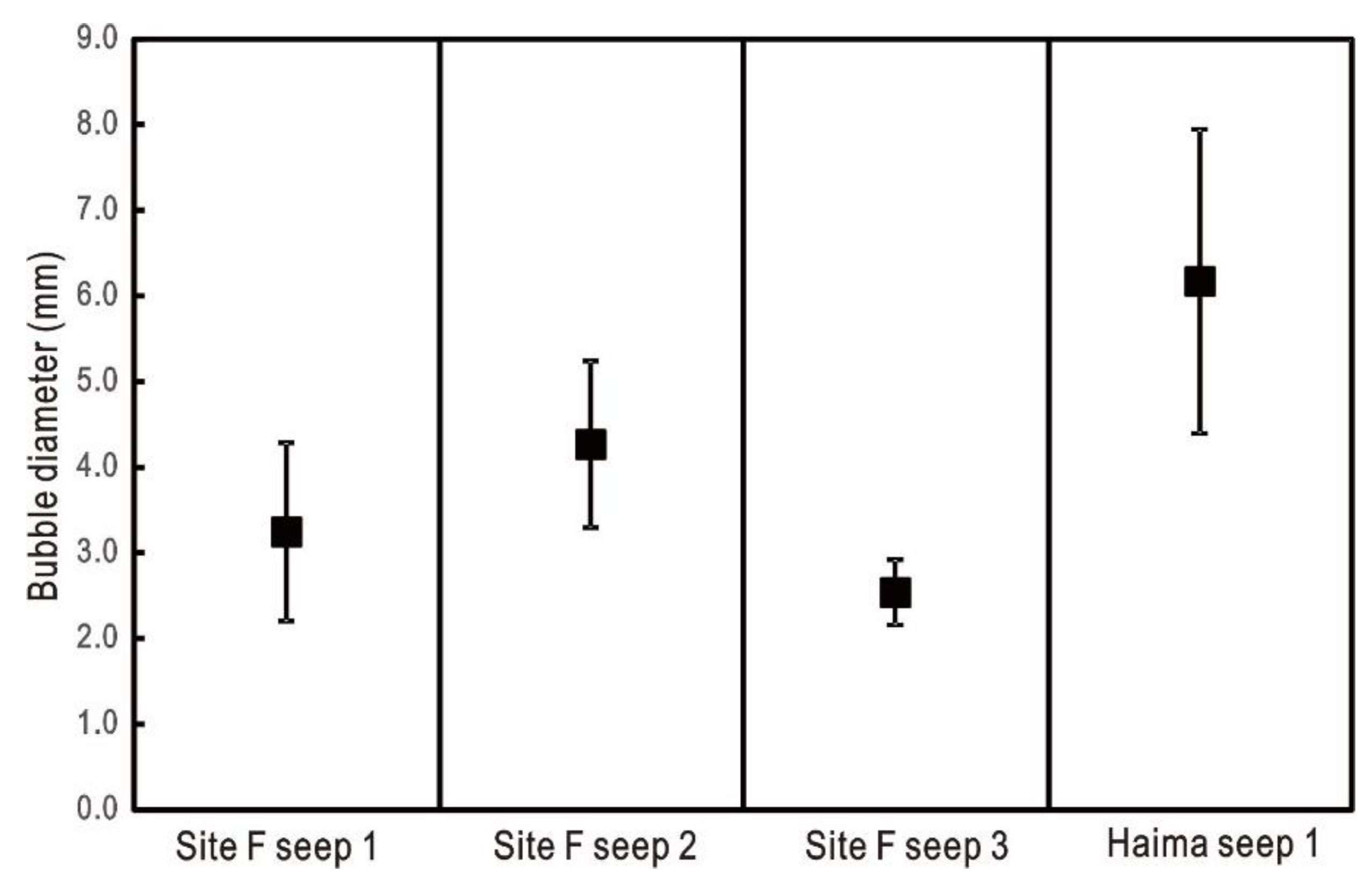
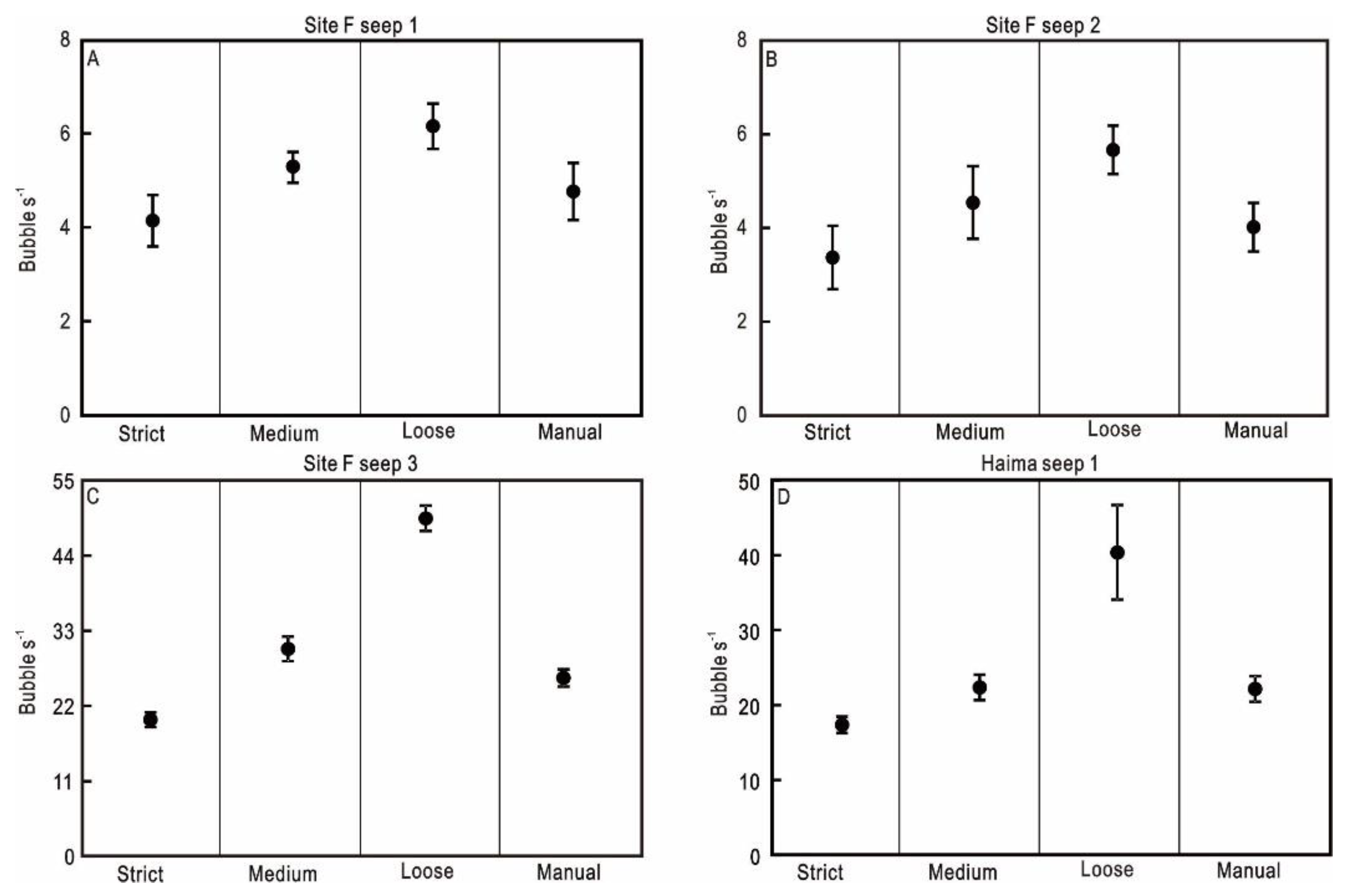
Individual bubble size distributions and average bubble diameters are shown in Figure 4 and Figure 5, respectively. The average bubble diameters at the four seeps are 3.25, 4.27, 2.54, and 6.17 mm (Figure 4 and Figure 5), which are approximately equivalent to the reported bubble size at five vents in the Gulf of Mexico (3.0–5.0 mm) [24,33]. It is well known that bubble release rates vary between different vents. However, due to noise, it is difficult to accurately determine bubble release rates. Therefore, three different threshold values (loose, medium, and strict) were adopted to address noise issues using the method of [24] (Figure 3). We found that the bubble release rates at the four seeps determined using the medium threshold value were closer to the manually determined bubble release rates than release rates determined using the strict value (Figure 6). In Table 1, we, therefore, report bubble release rates calculated using medium threshold values.

4.4. Methane Bubble Flux

Methane bubble flux and molar flux were estimated from each measurement and are reported in Table 1. Bubble size, bubble rise velocity, and bubble release rates were calculated using Equation (3) and were key parameters in the quantification of the total methane gas flux from each vent [8,24]. Based on the gas constant of methane at depth, the amount of gas per bubble (mole), and extrapolating annual amounts of CH4 is calculated more reliable. In terms of total carbon release, describing methane flow in mole values may lead to an underestimation since higher hydrocarbons are not considered, e.g., Mega Plumes 1 and 2 in [24]. However, because it was assumed that pure methane was released from the Site F and Haima cold seeps [57,58,59], the volume and gas amount (moles) were calculated separately for each bubble size measurement and then averaged for more accurate results. The estimated methane bubble flow rates for seeps 1–3 at Site F were 0.4, 4.4, and 0.1 L h−1, respectively, and seep 1 of the Haima cold seeps yielded a rate of 12.6 L h−1. Using estimates for the density of methane gas based on temperature and pressure, the methane mass flux was also calculated (97.5 and 122.9 kg m−3 for Site F and Haima cold seeps, respectively).

5. Discussion

5.1. Temporospatial Variations in Bubble Characteristics and Gas Flux Comparisons

We had only a short time over which to measure bubble sizes due to the limited working hours of the ROVs. The bubble sizes showed no significant variations over time, and their ranges fell within a normal distribution (Figure 5). We compared bubble sizes and rates between all four seep vents and found that the values for both bubble size and methane bubble flux at seep 1 of the Haima cold seeps were much higher than those from all three seeps at Site F (Table 1). In addition, the bubble size and methane bubble flux at Site F seep 2 was much higher than that at Site F seep 1 and seep 3 (Table 1). We suggest that differences in bubble size and bubble flux from the different seep vents may be related to seep conduit and orifice size [3].
Although different methods for quantifying bubble flux were used, our estimated annual methane flux is comparable to that of other studies that measured methane flux from individual vents in the Gulf of Mexico, Coal Oil Point seep field, Santa Barbara Channel, Hydrate Ridge, Black Sea, Lingtou Promontory, and Yinggehai Basin [23,24,55,56]. The average bubble flux reported for the Confetti vent (Mega plume GC600; 62–121 m3 yr−1) [24,33] is comparable to our measured values of 110 m3 yr−1 (8.48 × 10⁵ mol yr−1) at the Haima cold seeps and 43.6 m3 yr−1 (2.66 × 10⁵ mol yr−1) at Site F (Table 1). It is, however, less than the average bubble fluxes reported for the Sleeping Dragon vent (MC118 mega plume; 105–188 m3 yr−1), Santa Barbara Channel ((1825 ± 274) × 106 mol yr−1), Black Sea (0.9 × 10⁶ mol yr−1), and Lingtou Promontory seep area ((2.163–3.057) × 106 mol yr−1) [5,7,24,33,55,60]. In addition, due to the unknown methane diffusive flux into the water column, we cannot simply extrapolate the entire bubble flux of the SCS from bubble release rates of individual vents, especially based on data sets collected over short time intervals. Therefore, to more accurately estimate the total methane bubble flux in the SCS, we need to measure multiple seep vents in different seep areas over long time intervals and quantify the number of seep vents in the seep area using hydroacoustic surveys.
Due to the limited working time of the ROVs [3,24], we could not make long-term in situ observations of gas bubbles released from the cold seep vents and obtained only 20 min of video at each of the four seep vents. Although we observed gas bubbles from seep vents using ROV camera systems [3,23,27,32,33], the accuracy of our results is supported by their similarity to results of [24,33]. Furthermore, the SABCA approach was adopted to calculate the bubble flux for video acquisition [24]. This is a method adapted to a variety of settings [32] and is seen as a more versatile technique for in situ camera deployment. However, it did not allow us to acquire a time series of bubble release rates and details of activity characteristics, emphasizing the need to conduct long-term in situ observations of active cold seeps.

5.2. Factors Influencing Methane Bubble Flux

Cold seeps usually connect oil and gas reservoirs through plumbing systems or conduit networks such as subsurface fractures and faults. Methane bubble seep is driven by a pressure difference between the reservoir pressure and the hydrostatic pressure along multiple migration pathways, with higher methane bubble fluxes typically associated with higher permeability pathways [21]. In order to model these complex methane bubble seep systems, an effective seep electrical model was adopted [7,22]. In this model, the electrical circuit components represent methane fluid dynamic processes driven by an oil or gas reservoir [22]. The resistors R represent the viscosity of the interconnecting fluids and microbial filters that impede methane fluid emissions, and the capacitors C represent the strength and volume of the migration pathways and shallow reservoirs [61]. Due to the interconnectedness, variations in seep flux at different seep vents are related to pressure differences and flow resistances in the seep channels. Where permeability is very low, the methane flux is also very low, for example at Site F seep 1 and seep 2. Moreover, variations in seep flux at Site F seep 2 correlated more strongly with changes in methane flux at Site F seep 1 and seep 3 as they are very closely connected. It is possible that the migration pathway connecting the shallow reservoir was blocked, leading to a reduction in methane bubble flux at Site F seep 1 and seep 2. The increased shallow reservoir pressure caused by this blockage would drive flow through other connected migration pathways, with a greater increase where there are high flow rates, such as in Site F seep 2. Therefore, variations in methane bubble flux and permeability of the migration pathways at different seep vents drive the interplay between the seep vents [7,62].
Bubble seep rates are also affected by gas hydrate mounds, gas pressurization in reservoirs, tidal pressure fluctuations, and differential loading of sedimentary layers [7,55,56,62,63,64,65]. Our study sites had high sedimentation rates (10.2 cm ka−1) [66] and are located in the gas hydrate stability zone, where gas hydrates form within the sediment due to continuous methane migration. The pores in bubble vents generally pass through the sediment or through carbonate fractures, as we have captured in videos. It is therefore suggested that high sedimentation rates or the presence of massive carbonate rocks will influence the local compressibility of the seafloor and might alter the characteristics of bubble activity.
In recent years, much attention has been paid to the contribution of marine methane seeps to atmospheric methane budgets [67]. Methane bubbles released from cold seeps may reach the surface and enter the atmosphere directly or dissolve in the mixed layer and become released to the atmosphere through seawater–air exchange [10]. According to the CTD data and the observed height of the bubble plumes [25,68], areas of methane enrichment may be located at the depth of bubble plume dissipation or higher than the plume height [49,69]. Although methane continuously outgasses from rising bubbles within the hydrate stability zone, the maxima in methane concentrations may not extend into the mixed layer (<50 m) in the SCS [70,71]. Therefore, the methane outgassed from rising bubbles may not directly influence the accumulation of atmospheric methane and may be a negligible source of methane to the atmosphere. In addition, seep methane deposited below the mixed layer depth may be transported away from seep vents due to complex local currents and eventually become oxidized to carbon dioxide through methanotrophic microbial processes that can promote the phytoplankton and chlorophyll growth [72]. Furthermore, the deposition of methane at the depth of bubble plume dissipation may sustain methanotrophy within the water column [69].

6. Conclusions

We present the first measurements of bubble size, bubble flow rate, and bubble flux at one seep vent in Haima and three seep vents at Site F in the SCS. This was achieved by collecting high-definition video clips over a short period of time (20 min) and using a reproducible and adaptable image-processing method and a semi-automatic bubble counting algorithm. The bubbles released from the two seep areas are all gaseous. The bubble size distributions were stable at Site F and Haima cold seeps, and the measurements from each seep fit well to a log-normal distribution, with average bubble diameters between 2.54 mm and 6.17 mm. The average bubble diameters and bubble release rates from Site F (3.35 ± 0.79 mm at a rate of 11.6 bubbles s−1) are lower than those in the Haima cold seeps (6.17 ± 1.78 mm at a rate of 22.6 bubbles s−1), which may be attributed to a variety of factors, such as the nature of the gas reservoir, hydrostatic pressure, migration pathways in the sediments, and pore size. The reported methane bubble fluxes in the two seep areas suggest that cold seeps in the SCS are an important source of methane to the ocean. However, it was not possible to constrain temporal variations in bubble release rate and activity characteristic of the bubbles, due to limited observation time at the four seeps. Long-term observations of cold seeps over a much wider area are required to further constrain the characteristics of seep activity and the details of seep processes.

Author Contributions

Conceptualization: P.D.; methodology: P.D.; formal analysis: P.D.; investigation: P.D. and D.F.; resources: D.F. and J.T.; data curation: P.D.; writing—original draft preparation: P.D. and D.F.; writing—review and editing: P.D., D.F. and D.C.; project administration: P.D.; funding acquisition: P.D. All authors have read and agreed to the published version of the manuscript.

Funding

This study was partially supported by the National Key R&D Program of China (2018YFC0310003 and 2017YFC0307704), the National Natural Science Foundation of China (41676046, 41730528, and 91228206), the Qingdao National Laboratory for Marine Science and Technology (QNLM2016ORP0204), the Guangdong Basic and Applied Basic Research Foundation (2019A1515011809), and the Key Special Project for Introduced Talents Team of Southern Marine Science and Engineering Guangdong Laboratory (Guangzhou) (GML2019ZD0104).

Acknowledgments

We express our sincere appreciation to the crews of the ROV Haima, ROV ROPOS, and the research vessels Haiyang-06 and Tan Kah Kee for their support at sea.

Conflicts of Interest

The authors declare no conflict of interest.

References

  1. Garcia-Pineda, O.; MacDonald, I.; Zimmer, B.; Shedd, B.; Roberts, H. Remote sensing evaluation of geophysical anomaly sites in the outer continental slope, northern Gulf of Mexico. Deep Sea Res. II 2010, 57, 1859–1869. [Google Scholar] [CrossRef]
  2. Leifer, I.; Kamerling, M.; Luyendyk, B.; Wilson, D. Geologic control of natural marine hydrocarbon seep emissions, Coal Oil Point seep field, California. Geo Mar. Lett. 2010, 30, 331–338. [Google Scholar] [CrossRef]
  3. Leifer, I.; MacDonald, I. Dynamics of the gas flux from shallow gas hydrate deposits: Interaction between oily hydrate bubbles and the oceanic environment. Earth Planet. Sci. Lett. 2003, 210, 411–424. [Google Scholar] [CrossRef]
  4. Römer, M.; Sahling, H.; Pape, T.; Bahr, A.; Feseker, T.; Wintersteller, P.; Bohrmann, G. Geological control and magnitude of methane ebullition from a high-flux seep area in the Black Sea—the Kerch seep area. Mar. Geol. 2012, 319–322, 57–74. [Google Scholar] [CrossRef]
  5. Sahling, H.; Bohrmann, G.; Artemov, Y.G.; Bahr, A.; Brüning, M.; Klapp, S.A.; Klaucke, I.; Kozlova, E.; Nikolovska, A.; Pape, T.; et al. Vodyanitskii mud volcano, Sorokin trough, Black Sea: Geological characterization and quantification of gas bubble streams. Mar. Petrol. Geol. 2009, 26, 1799–1811. [Google Scholar] [CrossRef]
  6. Sauter, E.J.; Muyakshin, S.I.; Charlou, J.-L.; Schlüter, M.; Boetius, A.; Jerosch, K.; Damm, E.; Foucher, J.-P.; Klages, M. Methane discharge from a deep-sea submarine mud volcano into the upper water column by gas hydrate-coated methane bubbles. Earth Planet. Sci. Lett. 2006, 243, 354–365. [Google Scholar] [CrossRef] [Green Version]
  7. Leifer, I.; Boles, J. Measurement of marine hydrocarbon seep flow through fractured rock and unconsolidated sediment. Mar. Petrol. Geol. 2005, 22, 551–568. [Google Scholar] [CrossRef]
  8. Leifer, I. Seabed bubble flux estimation by calibrated video survey for a large blowout seep in the North Sea. Mar. Petrol. Geol. 2015, 68, 743–752. [Google Scholar] [CrossRef]
  9. Judd, A. Natural seabed gas seeps as sources of atmospheric methane. Environ. Geol. 2004, 46, 988–996. [Google Scholar] [CrossRef]
  10. Solomon, E.A.; Kastner, M.; MacDonald, I.R.; Leifer, I. Considerable methane fluxes to the atmosphere from hydrocarbon seeps in the Gulf of Mexico. Nat. Geosci. 2009, 2, 561–565. [Google Scholar] [CrossRef]
  11. Myrhe, G.; Shindell, D.; Bréon, F.-M.; Collins, W.; Fuglestvedt, J.; Huang, J.; Koch, D.; Lamarque, J.-F.; Lee, D.; Mendoza, B.; et al. Anthropogenic and natural radiative forcing. In Climate Change 2013: The Physical Science Basis: Working Group I Contribution to the Fifth Assessment Report of the Intergovernmental Panel on Climate Change; Stocker, T.F., Qin, D., Plattner, G.-K., Tignor, M., Allen, S.K., Boschung, J., Nauels, A., Xia, Y., Bex, V., Midgley, P.M., Eds.; Cambridge University Press: Cambridge, UK, 2013; pp. 659–740. [Google Scholar]
  12. Prather, M.J.; Holmes, C.D.; Hsu, J. Reactive greenhouse gas scenarios: Systematic exploration of uncertainties and the role of atmospheric chemistry. Geophys. Res. Lett. 2012, 39, L09803. [Google Scholar] [CrossRef] [Green Version]
  13. Etiope, G. Natural emissions of methane from geological seepage in Europe. Atmos. Environ. 2009, 43, 1430–1443. [Google Scholar] [CrossRef]
  14. Etiope, G.; Milkov, A. A new estimate of global methane flux from onshore and shallow submarine mud volcanoes to the atmosphere. Environ. Geol. 2004, 46, 997–1002. [Google Scholar] [CrossRef]
  15. Etiope, G.; Lassey, K.R.; Klusman, R.W.; Boschi, E. Reappraisal of the fossil methane budget and related emission from geologic sources. Geophys. Res. Lett. 2008, 35, L09307. [Google Scholar] [CrossRef]
  16. De Beukelaer, S.M.; MacDonald, I.R.; Guinnasso, N.L.; Murray, J.A. Distinct side-scan sonar, RADARSAT SAR, and acoustic profiler signatures of gas and oil seeps on the Gulf of Mexico slope. Geo Mar. Lett. 2003, 23, 177–186. [Google Scholar] [CrossRef]
  17. Judd, A.G.; Hovland, M. Submarine Fluid Flow, the Impact on Geology, Biology, and the Marine Environment; Cambridge University Press: Cambridge, UK, 2007. [Google Scholar]
  18. MacDonald, I.R.; Bohrmann, G.; Escobar, E.; Abegg, F.; Blanchon, P.; Blinova, V.; Brückmann, W.; Drews, M.; Eisenhauer, A.; Han, X.; et al. Asphalt Volcanism and Chemosynthetic Life in the Campeche Knolls, Gulf of Mexico. Science 2004, 304, 999–1002. [Google Scholar] [CrossRef]
  19. Roberts, H.H.; Aharon, P. Hydrocarbon-derived carbonate buildups of the northern Gulf of Mexico continental slope: A review of submersible investigations. Geo Mar. Lett. 1994, 14, 135–148. [Google Scholar] [CrossRef]
  20. Suess, E. Marine cold seeps and their manifestations: Geological control, biogeochemical criteria and environmental conditions. Int. J. Earth Sci. 2014, 103, 1889–1916. [Google Scholar] [CrossRef]
  21. Argentino, C.; Conti, S.; Crutchley, G.J.; Fioroni, C.; Fontana, D.; Johnson, J.E. Methane-derived authigenic carbonates on accretionary ridges: Miocene case studies in the northern Apennines (Italy) compared with modern submarine counterparts. Mar. Pet. Geol. 2019, 102, 860–872. [Google Scholar] [CrossRef]
  22. Leifer, I. A Synthesis Review of Emissions and Fates for the Coal Oil Point Marine Hydrocarbon Seep Field and California Marine Seepage. Geofluids 2019, 2019, 1–48. [Google Scholar] [CrossRef] [Green Version]
  23. Wang, B.; Socolofsky, S.A. A deep-sea, high-speed, stereoscopic imaging system for in situ measurement of natural seep bubble and droplet characteristics. Deep Sea Res. I 2015, 104, 134–148. [Google Scholar] [CrossRef]
  24. Johansen, C.; Todd, A.C.; MacDonald, I.R. Time series video analysis of bubble release processes at natural hydrocarbon seeps in the Northern Gulf of Mexico. Mar. Petrol. Geol. 2017, 82, 21–34. [Google Scholar] [CrossRef] [Green Version]
  25. McGinnis, D.F.; Greinert, J.; Artemov, Y.; Beaubien, S.E.; Wüest, A. Fate of rising methane bubbles in: How much methane reaches the atmosphere? J. Geophys. Res. Ocean 2006, 111, 9. [Google Scholar] [CrossRef] [Green Version]
  26. Socolofsky, S.; Bhaumik, T. Double-Plume Integral Models for Near-Field Mixing in Multiphase Plumes. J. Hydraul. Eng. ASCE 2008, 134. [Google Scholar] [CrossRef]
  27. Bian, Y.; Dong, F.; Zhang, W.; Wang, H.; Tan, C.; Zhang, Z. 3D reconstruction of single rising bubble in water using digital image processing and characteristic matrix. Particuology 2013, 11, 170–183. [Google Scholar] [CrossRef]
  28. Kvenvolden, K.A. Gas hydrates-geological perspective and global change. Rev. Geophys. 1993, 31, 173–187. [Google Scholar] [CrossRef]
  29. Kvenvolden, K.A. Methane hydrate in the global organic carbon cycle. Terra Nova 2002, 14, 302–306. [Google Scholar] [CrossRef]
  30. MacDonald, I.R.; Garcia-Pineda, O.; Beet, A.; Daneshgar Asl, S.; Feng, L.; Graettinger, G.; French-McCay, D.; Holmes, J.; Hu, C.; Huffer, F.; et al. Natural and unnatural oil slicks in the Gulf of Mexico. J. Geophys. Res. Ocean. 2015, 120, 8364–8380. [Google Scholar] [CrossRef]
  31. Maslin, M.A.; Thomas, E. Balancing the deglacial global carbon budget: The hydrate factor. Quat. Sci. Rev. 2003, 22, 1729–1736. [Google Scholar] [CrossRef] [Green Version]
  32. Thomanek, K.; Zielinski, O.; Sahling, H.; Bohrmann, G. Automated gas bubble imaging at sea floor-a new method of in situ gas flux quantification. OS 2010, 6, 549–562. [Google Scholar]
  33. Wang, B.; Socolofsky, S.A.; Breier, J.A.; Seewald, J.S. Observations of bubbles in natural seep flares at MC 118 and GC 600 using in situ quantitative imaging. J. Geophys. Res. Ocean. 2016, 121, 2203–2230. [Google Scholar] [CrossRef] [Green Version]
  34. Grant, N.J.; Whiticar, M.J. Stable carbon isotopic evidence for methane oxidation in plumes above Hydrate Ridge, Cascadia Oregon Margin. Global Biogeochem. Cycles 2002, 16, 1124. [Google Scholar] [CrossRef]
  35. Greinert, J.; McGinnis, D.F.; Naudts, L.; Linke, P.; De Batist, M. Atmospheric methane flux from bubbling seeps: Spatially extrapolated quantification from a Black Sea shelf area. J. Geophys. Res. Ocean. 2010, 115, C01002. [Google Scholar] [CrossRef] [Green Version]
  36. Römer, M.; Sahling, H.; Pape, T.; dos Santos Ferreira, C.; Wenzhöfer, F.; Boetius, A.; Bohrmann, G. Methane fluxes and carbonate deposits at a cold seep area of the Central Nile Deep Sea Fan, Eastern Mediterranean Sea. Mar. Geol. 2014, 347, 27–42. [Google Scholar] [CrossRef]
  37. Sahling, H.; Römer, M.; Pape, T.; Bergès, B.; dos Santos Fereirra, C.; Boelmann, J.; Geprägs, P.; Tomczyk, M.; Nowald, N.; Dimmler, W.; et al. Gas emissions at the continental margin west of Svalbard: Mapping, sampling, and quantification. Biogeosciences 2014, 11, 6029–6046. [Google Scholar] [CrossRef] [Green Version]
  38. Valentine, D.L.; Blanton, D.C.; Reeburgh, W.S.; Kastner, M. Water column methane oxidation adjacent to an area of active hydrate dissociation, Eel river Basin. Geochim. Cosmochim. Acta 2001, 65, 2633–2640. [Google Scholar] [CrossRef] [Green Version]
  39. Feng, D.; Qiu, J.W.; Hu, Y.; Peckmann, J.; Guan, H.; Tong, H.; Chen, C.; Chen, J.; Gong, S.; Li, N.; et al. Cold seep systems in the South China Sea: An overview. J. Asian Earth Sci. 2018, 168, 3–16. [Google Scholar] [CrossRef]
  40. Liu, C.S.; Morita, S.; Liao, Y.H.; Ku, C.Y.; Machiyama, H.; Lin, S.; Soh, W. High resolution seismic images of the Formosa ridge off southwestern Taiwan where “hydrothermal” chemosynthetic community is present at a cold seep site. In Proceedings of the 6th International Conference on Gas Hydrates (ICGH 2008), Vancouver, BC, Canada, 6–10 July 2008. [Google Scholar]
  41. Liang, Q.; Hu, Y.; Feng, D.; Peckmann, J.; Chen, L.; Yang, S.; Liang, J.; Tao, J.; Chen, D. Authigenic carbonates from newly discovered active cold seeps on the northwestern slope of the South China Sea: Constraints on fluid sources, formation environments, and seepage dynamics. Deep Sea Res. I 2017, 124, 31–41. [Google Scholar] [CrossRef]
  42. Hovland, M.; Judd, A.G.; Burke, R.A. The global flux of methane from shallow submarine sediments. Chemosphere 1993, 26, 559–578. [Google Scholar] [CrossRef]
  43. Torres, M.E.; Wallmann, K.; Tréhu, A.M.; Bohrmann, G.; Borowski, W.S.; Tomaru, H. Gas hydrate growth, methane transport, and chloride enrichment at the southern summit of Hydrate Ridge, Cascadia margin off Oregon. Earth Planet. Sci. Lett. 2004, 226, 225–241. [Google Scholar] [CrossRef]
  44. Feng, D.; Cheng, M.; Kiel, S.; Qiu, J.-W.; Yang, Q.; Zhou, H.; Peng, Y.; Chen, D. Using Bathymodiolus tissue stable carbon, nitrogen and sulfur isotopes to infer biogeochemical process at a cold seep in the South China Sea. Deep Sea Res. I 2015, 104, 52–59. [Google Scholar] [CrossRef] [Green Version]
  45. Feng, D.; Chen, D. Authigenic carbonates from an active cold seep of the northern South China Sea: New insights into fluid sources and past seepage activity. Deep Sea Res. II 2015, 122, 74–83. [Google Scholar] [CrossRef]
  46. Gong, Z.S.; Li, S.T.; Xie, T. Continental Margin Basin Analysis and Hydrocarbon Accumulation of the Northern South China Sea; Beijing Science Press in Chinese: Beijing, China, 1997. [Google Scholar]
  47. Wang, J.; Wu, S.; Kong, X.; Ma, B.; Li, W.; Wang, D.; Gao, J.; Chen, W. Subsurface fluid flow at an active cold seep area in the Qiongdongnan Basin, northern South China Sea. J. Asian Earth Sci. 2018, 168, 17–26. [Google Scholar] [CrossRef]
  48. Sam, A.; Gomez, C.O.; Finch, J.A. Axial velocity profiles of single bubbles in water/frother solutions. Int. J. Miner. Process. 1996, 47, 177–196. [Google Scholar] [CrossRef]
  49. Calculation of thermodynamic state variables of methane. Available online: http://www.peacesoftware.de/einigewerte/methan_e.html (accessed on 27 February 2020).
  50. Leifer, I.; Judd, A.G. Oceanic methane layers: The hydrocarbon seep bubble deposition hypothesis. Terra Nova 2002, 14, 417–424. [Google Scholar] [CrossRef]
  51. Greene, C.; Wilson, P. Laboratory investigation of a passive acoustic method for measurement of underwater gas seep ebullition. J. Acoust. Soc. Am. 2012, 131, EL61–EL66. [Google Scholar] [CrossRef] [Green Version]
  52. Tilbrook, B.D.; Karl, D.M. Methane sources, distributions and sinks from California coastal waters to the oligotrophic North Pacific gyre. Mar. Chem. 1995, 49, 51–64. [Google Scholar] [CrossRef] [Green Version]
  53. Watanabe, S.; Higashitani, N.; Tsurushima, N.; Tsunogai, S. Methane in the western North Pacific. J. Oceanogr. 1995, 51, 39–60. [Google Scholar] [CrossRef]
  54. Zhou, H.; Yin, X.; Yang, Q.; Wang, H.; Wu, Z.; Bao, S. Distribution, source and flux of methane in the western Pearl River Estuary and northern South China Sea. Mar. Chem. 2009, 117, 21–31. [Google Scholar] [CrossRef]
  55. Di, P.; Feng, D.; Chen, D. In situ and on-line measurement of gas flux at a hydrocarbon seep from the northern South China Sea. Cont. Shelf Res. 2014, 81, 80–87. [Google Scholar] [CrossRef]
  56. Di, P.; Feng, D.; Chen, D. Temporal variation in natural gas seep rate and influence factors in the Lingtou Promontory seep field of the northern South China Sea. Terr. Atmos. Ocean. Sci. 2014, 25, 665–672. [Google Scholar] [CrossRef] [Green Version]
  57. Zhang, X.; Hester, K.C.; Ussler, W.; Walz, P.M.; Peltzer, E.T.; Brewer, P.G. In situ Raman-based measurements of high dissolved methane concentrations in hydrate-rich ocean sediments. Geophy. Res. Lett. 2011, 38, L08605. [Google Scholar] [CrossRef]
  58. Liang, J.; Zhang, W.; Lu, J.; Wei, J.; Kuang, Z.; He, Y. Geological occurrence and accumulation mechanism of natural gas hydrates in the eastern Qiongdongnan Basin of the South China Sea: Insights from site GMGS5-W9-2018. Mar. Geol. 2019, 106042. [Google Scholar] [CrossRef]
  59. Ye, J.; Wei, J.; Liang, J.; Lu, J.; Lu, H.; Zhang, W. Complex gas hydrate system in a gas chimney, South China Sea. Mar. Petrol. Geol. 2019, 104, 29–39. [Google Scholar] [CrossRef]
  60. Hornafius, J.S.; Quigley, D.; Luyendyk, B.P. The world’s most spectacular marine hydrocarbon seeps (Coal Oil Point, Santa Barbara Channel, California): Quantification of emissions. J. Geophys. Res. 1999, 104, 20703–20711. [Google Scholar] [CrossRef]
  61. Reeburgh, W.S. Oceanic methane biogeochemistry. Chem. Rev. 2007, 107, 486–513. [Google Scholar] [CrossRef] [PubMed] [Green Version]
  62. Klapp, S.A.; Bohrmann, G.; Kuhs, W.F.; Mangir Murshed, M.; Pape, T.; Klein, H.; Techmer, K.S.; Heeschen, K.U.; Abegg, F. Microstructures of structure I and II gas hydrates from the Gulf of Mexico. Mar. Petrol. Geol. 2010, 27, 116–125. [Google Scholar] [CrossRef]
  63. Clayton, C.; Hay, S. Gas migration mechanisms from accumulation to surface. Bull. Geol. Soc. Den. 1994, 41, 12–23. [Google Scholar]
  64. Krabbenhoeft, A.; Netzeband, G.L.; Bialas, J.; Papenberg, C. Episodic methane concentrations at seep sites on the upper slope Opouawe Bank, southern Hikurangi Margin, New Zealand. Mar. Geol. 2010, 272, 71–78. [Google Scholar] [CrossRef]
  65. Netzeband, G.L.; Krabbenhoeft, A.; Zillmer, M.; Petersen, C.J.; Papenberg, C.; Bialas, J. The structures beneath submarine methane seeps: Seismic evidence from Opouawe Bank, Hikurangi Margin, New Zealand. Mar. Geol. 2010, 272, 59–70. [Google Scholar] [CrossRef] [Green Version]
  66. Zhu, W. Petroleum geology in deepwater area of northern continental margin in South China Sea. Acta. Petrol. Sin. 2010, 31, 521–527. [Google Scholar]
  67. MacDonald, I.R.; Leifer, I.; Sassen, R.; Stine, P.; Mitchell, R.; Guinasso, N. Transfer of hydrocarbons from natural seeps to the water column and atmosphere. Geofluids 2002, 2, 95–107. [Google Scholar] [CrossRef]
  68. Yang, L.; Liu, B.; Xu, M.J.; Liu, S.X.; Guan, Y.X.; Gu, Y. Characteristics of active cold seepage in Qiongdongnan sea area of the northern South China Sea. Chin. J. Geophys. 2018, 61, 2905–2914. [Google Scholar]
  69. Philip, B.T.; Denny, A.R.; Solomon, E.A.; Kelley, D.S. Time-series measurements of bubble plume variability and water column methane distribution above Southern Hydrate Ridge, Oregon. Geochem. Geophy. Geosy. 2016, 17, 1182–1196. [Google Scholar] [CrossRef]
  70. Rehder, G.; Leifer, I.; Brewer, P.G.; Friederich, G.; Peltzer, E.T. Controls on methane bubble dissolution inside and outside the hydrate stability field from open ocean field experiments and numerical modeling. Mar. Chem. 2009, 114, 19–30. [Google Scholar] [CrossRef]
  71. Xiao, X.; Wang, D.; Zhou, W.; Zhang, Z.; Qin, Y.; He, N.; Zeng, L. Impacts of a wind stress and a buoyancy flux on the seasonal variation of mixing layer depth in the South China Sea. Acta Oceanol. Sin. 2013, 32, 30–37. [Google Scholar] [CrossRef]
  72. Thompson, R.E.; Krassovski, M.V. Poleward reach of the California Undercurrent extension. J. Geophys. Res. 2010, 115, C09027. [Google Scholar] [CrossRef]
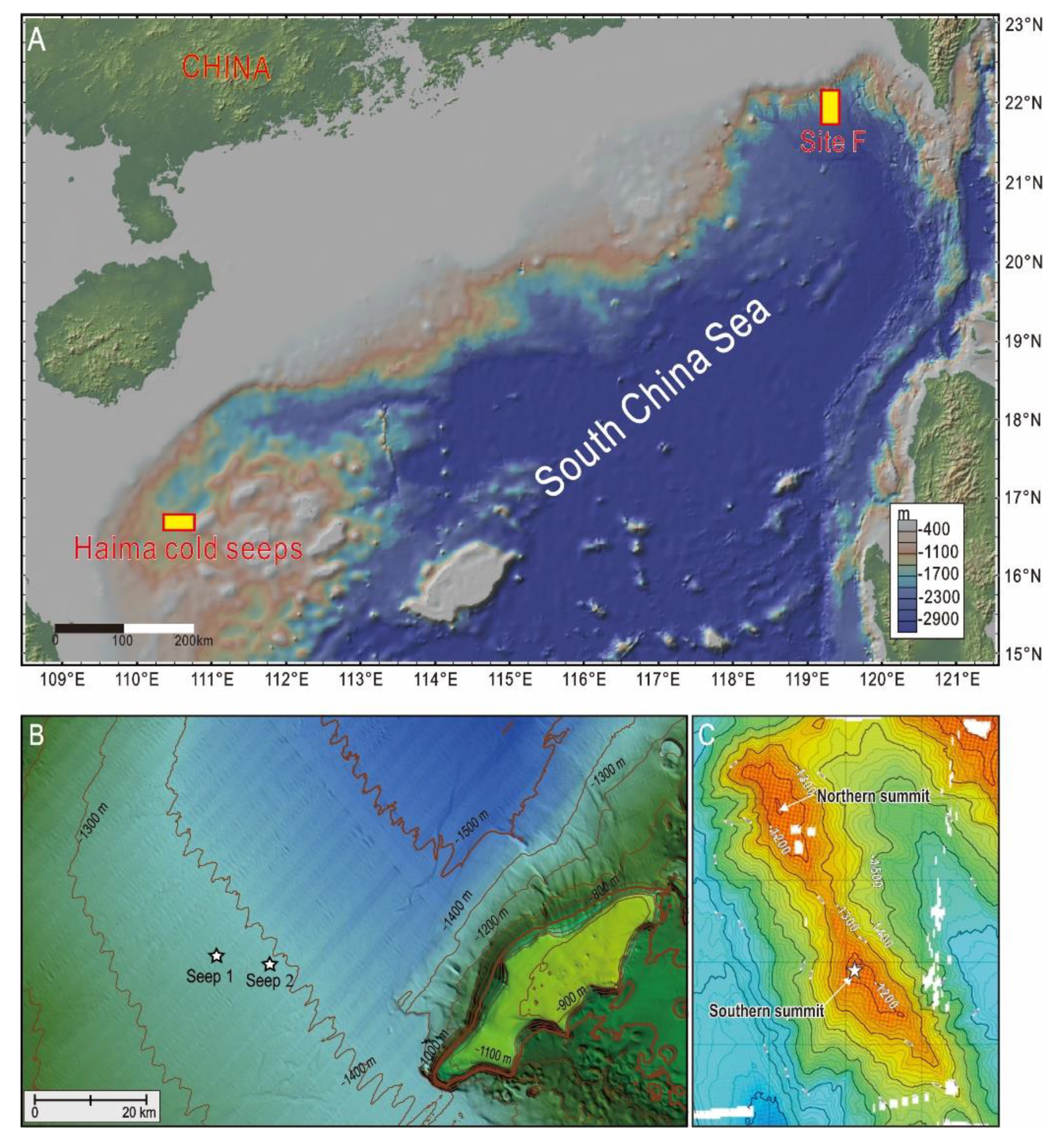
Figure 1. (A) Location of the two seep areas, Site F (1125 m) and Haima (1400 m). (B) Bathymetry map of the two active vents of the Haima cold seeps and their surroundings (provided by Professor Wei Li) with stars denoting the locations of the two vents. (C) Bathymetry map of the three active vents at Site F and their surroundings [44], which are located at the Southern summit of the Formosa ridge.
Minerals 10 00216 g001
Figure 2. Frame grabs of individual cold seep vents investigated in this study. (AC) Seep 1, Seep 2, and Seep 3 at Site F. The frame grabs show clearly that gas bubbles are escaping from pores in the carbonate pavements. Densely packed mussels (Bathymodiolus platifrons) and galatheid crabs (Shinkaia crosnieri) are also seen on freshly formed carbonate pavements. (D) Seep 1 of the Haima cold seeps. The gas bubble stream and gas hydrate slice are both clearly visible in the seawater, and packed mussels are seen scattered on the surrounding seafloor sediments. (E) Seep 2 of the Haima cold seeps. The frame grab from the camera shows clearly that dense streams of bubbles are escaping from the seabed. When these escaped bubbles entered the sample tube, they quickly formed gas hydrates. (F) Living tubeworms discovered in the Haima cold seeps.
Minerals 10 00216 g002
Figure 3. Schematic diagram depicting the image-processing method using the semi-automatic bubble counting algorithm. (A) Original image from which a cropped bubble counting area is determined and converted to grayscale. The cropped bubble counting area is subtracted from the consecutive image (B,C: frames 1 and 2) to delete a constant background and identify bubbles (bright spots in D). Three thresholds (high, medium, and low) were used to identify bubbles to account for bubble size, motion blurring, and oil content. (E) Bubbles are counted and subsampled in the counting region. Bubble count for each pixel line is summed across every frame in a clip, and total line counts are averaged to generate three values of bubble release for each threshold (high, medium, low) for one clip. This sequence was repeated for each clip to create a time series of bubble release for the entire deployment time.
Minerals 10 00216 g003
Figure 4. Individual size distributions of gaseous bubbles for the four seep vents. A smooth kernel distribution was used to fit the histogram, where n is the number of bubbles measured.
Minerals 10 00216 g004
Figure 5. Average bubble size (with standard deviations) at Site F and Haima cold seeps.
Minerals 10 00216 g005
Figure 6. Average bubble release rates (with standard deviations) for each vent considering the different thresholds (strict, medium, and loose) and the manual cross-check count. (A) Site F seep 1; (B) Site F seep 2; (C) Site F seep 3; (D) Haima seep 1.
Minerals 10 00216 g006
Table 1. Summary of cold seep sites, video samples, measurement results, and seep flow rate estimates for individual imaging bursts.
SiteSeepDepth (m)Sampling
Frequency (s)
Data
Range (min)
Activity
Type
Seep
Type
Release Rate
(Bubbles s−1)
Avg. Bubble
Diameter (mm)
Bubble Volume
at Depth (mm3)
Gas Amount per Bubble (mol)Annual Release (mol yr−1)Annual Release (m3 yr−1)Annual Mass Flow (T yr−1)
Site FSeep 111251010discontinuousGaseous4.8 ± 0.613.25 ± 1.0423.42 ± 21.021.43 × 10−4 ± 1.28 × 10−42.16 × 1043.550.35
seep 211272020continuousGaseous26.1 ± 0.674.27 ± 0.9747.25 ± 33.722.88 × 10−4 ± 2.05 × 10−42.37 × 10538.93.79
seep 311241510continuousGaseous4.0 ± 0.522.54 ± 0.389.11 ± 3.925.55 × 10−5 ± 2.39 × 10−57.00 × 1031.150.11
Haimaseep 113951020continuousGaseous22.4 ± 1.696.17 ± 1.78156.07 ± 149.61.20 × 10−3 ± 1.15 × 10−38.48 × 10511013.5
seep 21382104continuousGaseous-------